

Page 1
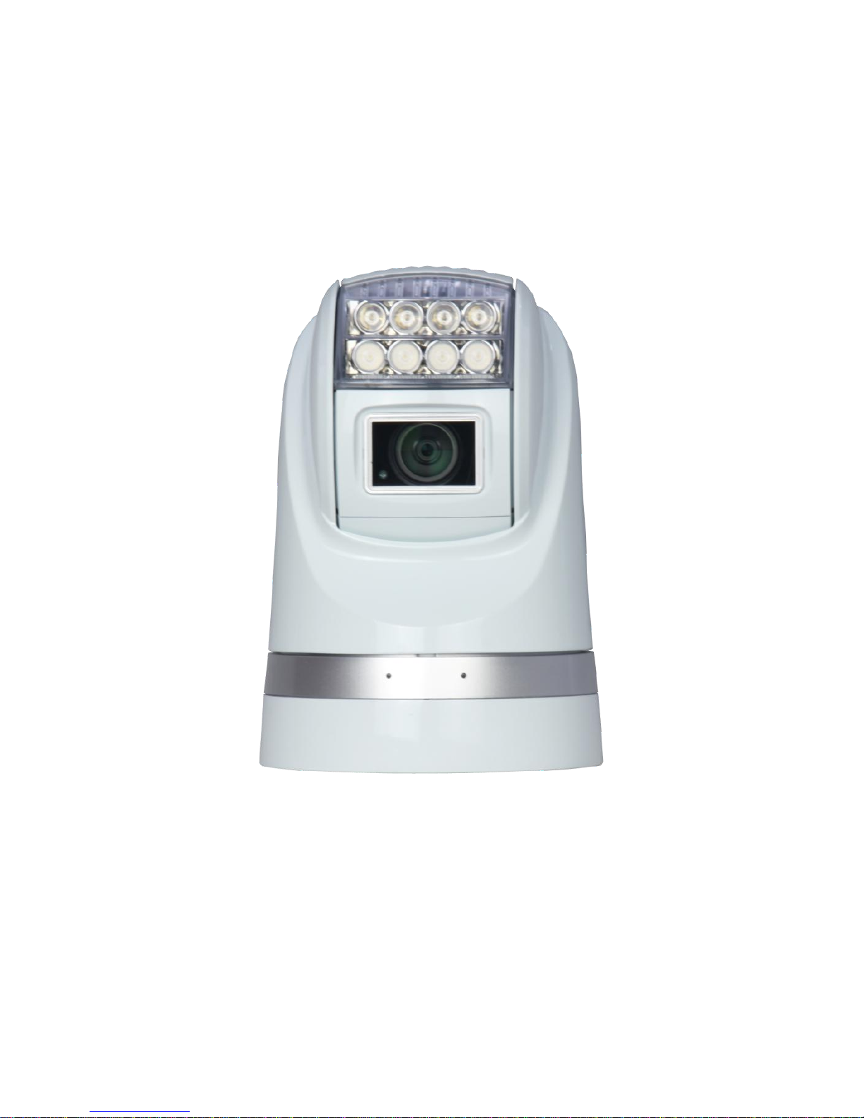
USER MANUAL
HD Portable All-Condition Rugged PTZ Camera
(IR and White Light Versions)
Page 2

Page 3

Safety Notes
Thank You for Choosing Our HD Portable All-Condition Rugged PTZ Camera!
When you open the box:
1. Check that the packing and the contents are not visibly damaged. Contact the retailer
immediately if any parts are either missing or damaged.
2. Make sure if the contents are all included as per the packing list.
3. Do not attempt to use the device with missing or damaged parts. Send the product back in its
original packing if it is damaged.
[Note] The information contained in the document is subject to change without notice.
Page 4

Table of Contents
Safety Notes..................................................................................................... 1
About The Product .......................................................................................... 2
Features ......................................................................................................... 2
Functions ........................................................................................................ 3
Technical Data ............................................................................................... 6
Preparation ...................................................................................................... 8
Dip Switch ...................................................................................................... 8
Initial Power On Test ...................................................................................... 9
Installation Place .......................................................................................... 10
Installation ..................................................................................................... 11
Fixed Mounts ................................................................................................ 11
Installation .................................................................................................... 12
Camera Cable Package ............................................................................... 13
MENU SETTINGS ........................................................................................... 15
Menu Configuration ...................................................................................... 15
Menu Explanation ......................................................................................... 16
Operation ....................................................................................................... 23
Special Control Panel Commands ............................................................... 23
Operation ...................................................................................................... 24
Trouble Shooting .......................................................................................... 27
Annex: Dip Switch – Camera Address ........................................................ 28
Page 5

1
Safety Notes --- Important!!!
The following important notes must be followed carefully to run the camera and respective
accessories in total safety. The camera and relative accessories are called video system in this
section.
Before installing the camera, please read this manual carefully; when installing please follow
instructions of installation indicated in this manual. Please keep this manual for future use.
The following installation should be performed by qualified service personnel or system installers
in accordance with all local rules.
Before powering on the camera, please check the power voltage carefully. Make sure that you
are using the right power source.
Please put the power cable, video cable and control cable in safe place.
Do not operate the camera beyond the specified temperature and humidity. The camera’s working
temperature range is between -45℃~+65℃. The ambient humidity range is less than 95﹪.
When transporting, avoid violent shake or force to the camera.
To prevent electric shock, do not remove screws or covers of the camera. There are no
self-serviceable parts inside. Refer to qualified service personnel for servicing.
Video cable and RS485 cable should be far away from other cables. Shielded and independent
wiring is necessary for video and control cables.
Never aim the lens of the camera at the sun or other extremely bright objects. Otherwise, it may
cause damage.
When cleaning the camera, please use soft cloth. If the camera is very dirty, wipe it off gently
with a soft cloth moistened with a weak solution of water and a neutral kitchen detergent. Wring
all liquid from the cloth before wiping the camera, then wipe off all remaining dirt with a soft, dry
cloth. Use lens cleaning paper to clean the lens.
Do not move the camera module manually. In doing so would result in malfunction of the camera.
Do not hold the camera module when carrying the video camera.
Make sure the camera is far away from area where radiation, X-rays, strong electric waves, or
magnetism is generated.
Page 6

2
About The Product
PAHC series camera is designed for fixed and mobile video surveillance applications, such as
marine, law enforcement, army, border patrol, airport, oilfield etc.
It consists of: high resolution zoom module, powerful IR or white lighting module, precise PTZ
system, optional damping systems.
Aux Lighting System
Powerful IR lighting or white lighting systems with ranges up to 120 meters. It ensures clear view of
details in distance up to 120 meter under total dark environments.
Full Aluminum PTZ Case
The case with high strength is full weather proof, suitable for various tough applications such as
rugged roads, sea, storm weather etc.
New Drive Mechanism
The PTZ camera employs new drive system with high precision and higher holding torque. It does
not generate offset during positioning of Pan and Tilt.
Easy Installation Mounts
The new vacuum and magnetic vacuum can easily fix the PTZ camera firmly onto a metal surface.
Meanwhile user can easily carry the PTZ camera with the handle at the back side.
Features
Supports 1080p/30,1080p/25,1080i/60,1080i/50,720p/60,720p/50,720p/30,720p/25 and SD
video formats;
Aluminum PTZ case with high strength, full weather proof;
IP index up to IP67;
Optional damping system, for tough applications;
Powerful IR lighting module, range up to 120 meters, auto adjust with zooms (for IR Version
only);
Powerful aux white lighting system, range up to 120 meters (for White Light Version only);
Hidden seamless window wiper with adjustable speed;
Page 7

About The Product
3
New design of drive system, PTZ positioning precision up to +/-0.05°;
Camera address easily changeable via software;
Baud rate, protocol self-adaptive;
Digital image stabilization;
Image flip for stand / ceiling mount;
Video freeze;
20X optical zoom;
Wide Dynamic Range (WDR);
Day/night (ICR);
10.8~28V voltage input;
Auto power-off with low power supply;
Auto flip;
OSD.
Functions
Soft Address
The camera address can be programmed with a preset command, and the user does not need to
dismount the camera from field or do any screw work.
Self-Adaption of Baud Rate and Protocol
The camera can automatically identify the protocol and baud rate of the controller and adapt the
camera setting accordingly, with no manual DIP Switch involved.
Day/Night Function
The IR cut filter of camera module inside the camera can be removed by sending special command,
so that the camera can change from color to mono.
Page 8

About The Product
4
Save/Call Preset
Preset function is that dome saves current horizontal angle and title angle of pan/tilt, zoom and
position parameters into memory. When necessary dome calls these parameters and adjusts
Pan/Tilt and camera to that position. User can save and call presets easily and promptly by using
keyboard controller or infrared controller. The camera supports up to 256 presets.
Zoom control
User can adjust zoom wide or tele by controller and get desired image.
Focus control
System defaults Auto Focus mode, that is, the lens and camera will automatically adjust the focus
to get the best image.
Focus can also be controlled manually from the controller if required. Press Focus Near or Focus
Far key to manually focus. Focus can be manual via keyboard or other controller, please refer to
control keyboard or other controller operation manual for detailed operation.
The camera will NOT auto focus in the following status.
Target is not in the center of image.
Targets are in near and far at the same time.
Target is of strong light object. Such as spotlight etc.
Target is behind the glass with water drop or dust.
Target moves too fast.
Large area target such as wall.
Target is too dark or vague.
IRIS control
System defaults Auto IRIS. Camera can adjust immediately according to the alteration of back
ground illumination so that a lightness steady image can be achieved.
You may adjust IRIS by controller to get required image brightness, and call back Auto IRIS by
controlling the joystick.
Page 9

About The Product
5
Auto White Balance
Camera can automatically adjust white balance (WB) according to the alteration of background
lightness to give a true color image.
Back Light Compensation (BLC)
If a bright backlight presents, the subjects in the picture may appear dark or as a silhouette.
Backlight compensation enhances objects in the center of the picture. The camera uses the center
of the picture to adjust the IRIS. If there is a bright light source outside this area, it will wash out to
white. The camera will adjust the IRIS so that the object in the sensitive area is properly exposed.
Auto Cruise
The preset position is programmed to be recalled in sequence. This feature is called auto cruise.
Auto, Random and Frame Scan
Auto Scan: Make the camera scan 360° ranging from the current position.
Random Scan: Make the camera scan 360º ranging from the current position, pause at every 108 º.
Frame Scan: Make the camera scan between two set positions.
Image Flip
Enable you to view image easily when PTZ is either installed upside down or upright.
Auto Flip
When the camera tilts downward and goes just beyond the vertical angle, the camera rotates 180º.
When the camera rotates (flips), the camera starts moving upward as you continue to hold joystick
in the down position. Once you let go of the joystick after the dome rotates, joystick control returns
to normal operation. The auto-flip feature is useful for following a person who passes directly
beneath the camera.
[Note] For Frame Scan: The zoom at two limits shall be programmed the same.
Page 10
About The Product
6
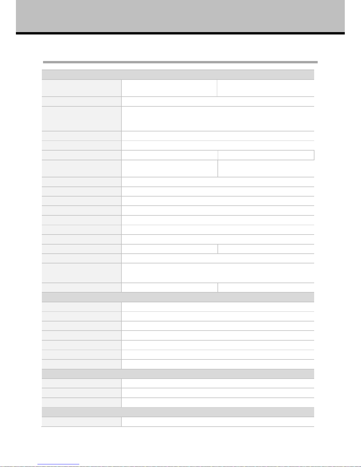
Technical Data
Camera
Image Sensor
1/2.8 type solid state Progressive
Scan CMOS
1/2.8” SONY EX-View HAD CCD
Effective Pixel
1920(H)×1080(V)
Video Format
HD:1080p/30,1080p/25,1080i/60,1080i/50,720p/60,720p/50,720p/30,
720p/25
SD: PAL/NTSC
Video System
PAL/NTSC
Optical Zoom
20X
Digital Zoom
-
12X
Min Illumination
0.4Lux (Lights Off)
0.04Lux (Lights On)
0.5Lux (Lights Off)
0.095Lux (Lights On)
White Balance
Auto
Focus
Auto/Manual
Exposure
Auto/Manual
S/N Ratio
Not less than 50DB
BLC
On/Off
WDR
Yes
Image Stabilization
On/Off
Digital Noise Reduction
1~3 Steps, OFF
1~5 Steps, OFF
Day/Night
Auto(only for IR version)/Manual
Lens
f=4.7mm~94mm
F1.6 to F3.5
View Angle
55.2° (wide) to 2.9°(tele)
55.4°(wide) to 2.9° (tele)
PTZ
Pan Range
360° continuous
Pan Speed
0.04° -90°/s, adjustable
Tilt Range
-15°~90° with auto flip
Tilt Speed
0.3° ~60°/s adjustable
Preset Speed
Pan: 120°/s; Tilt: 90°/s
Preset
256
Preset Precision
±0.05°
Light (for IR Version)
IR Wave Length
850nm/940nm
IR Range
120m/60m
IR Switch
Auto/Manual
Light (for White Light Version)
Color Temperature
6500K
Page 11
About The Product
7
Range
120m
Switch
Manual
General
Comm. Interface
RS-485
OSD Language
English
Protocol
PELCO-P / PELCO-D(self-adaptive)
Baud Rate
2400bps, 4800bps, 9600bps, 19200bps (self-adaptive)
Address
0-255
Voltage
DC 10.8-28V
Power
12W (Standby)
55W (Defogger and lights on)
Working Temperature
-45℃~+65℃
IP Index
IP67, TVS
Dimensions
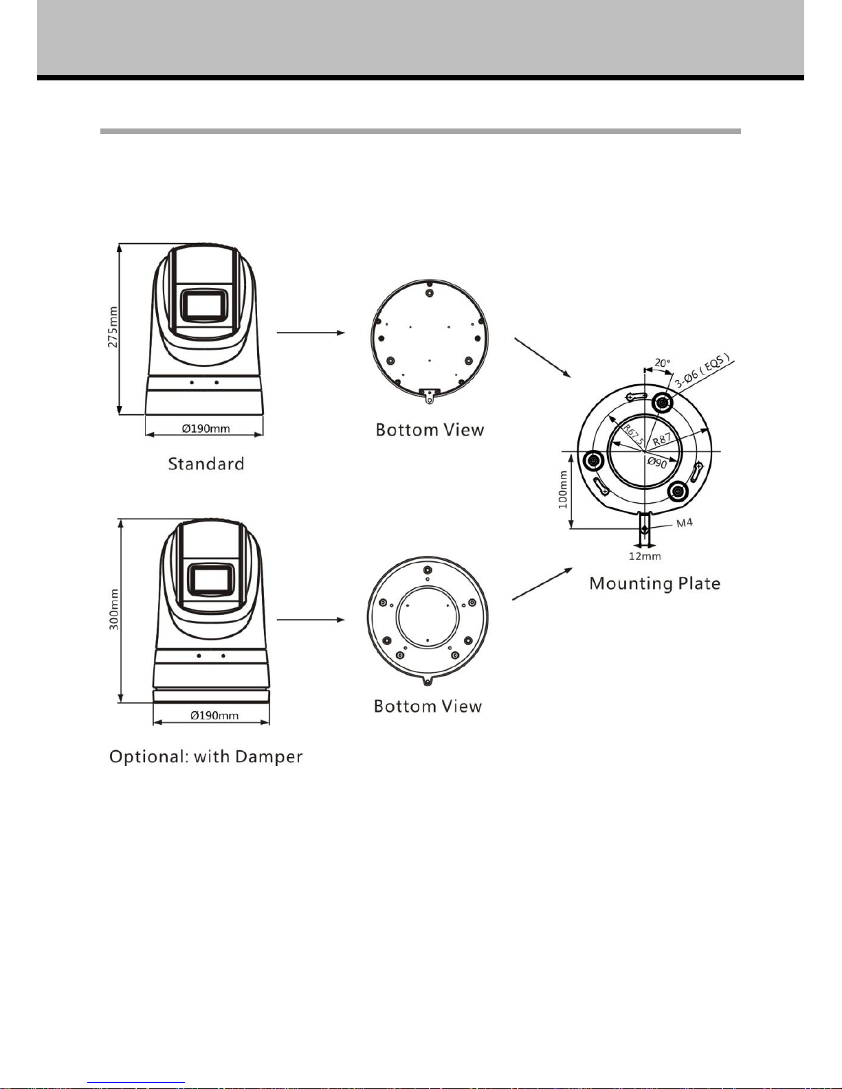
Standard: Φ190(mm)×275(mm)
With Damper: Φ190(mm)×300(mm)
Weight
Standard: 4.9kg
Optional: 5.65kg (with damper)
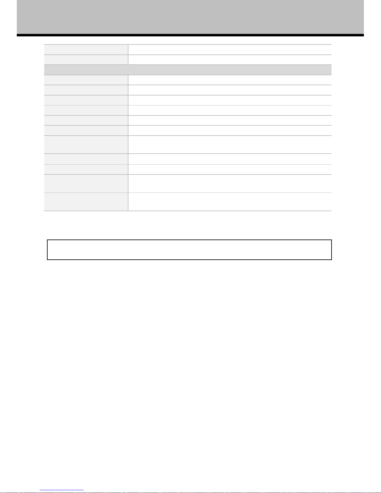
Table 1: Technical Data
[Note] The specifications are subject to change without notice.
Page 12
8
Preparation
This section contains detailed instructions for installing the camera. These instructions assume that
the installer has a good knowledge of installation techniques and is capable of adopting safe
installation methods.
Dip Switch
The factory default is:
Camera Address
Protocol
Baud Rate
1
Pelco D
9600bps
The camera can detect and auto program its protocol (Pelco D, Pelco P) as well as baud rate
(2400bps, 4800bps, 9600bps, 19200bps) as per the whole video system.
Only the camera address setting is necessary. There are two ways to program camera address:
Soft address: via special preset functions (see Section 5.1 Special Control Panel Commands);
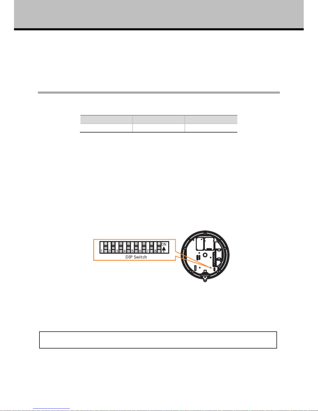
DIP Switch: The switches to configure these settings are located on the main board inside the
camera. See Fig. 1: DIP Switch.
Fig. 1: DIP Switch
The setting list of the camera address is enclosed in Annex.
[Note] The camera shall be rebooted after the switches are programmed.
Page 13
9
Preparation
Initial Power On Test
To ensure the camera works well after installation, please power on it for an initial test with the
following steps:
1. Connect the camera with correct power supply;
2. Connect control cable, video cable;
3. Power on the camera;
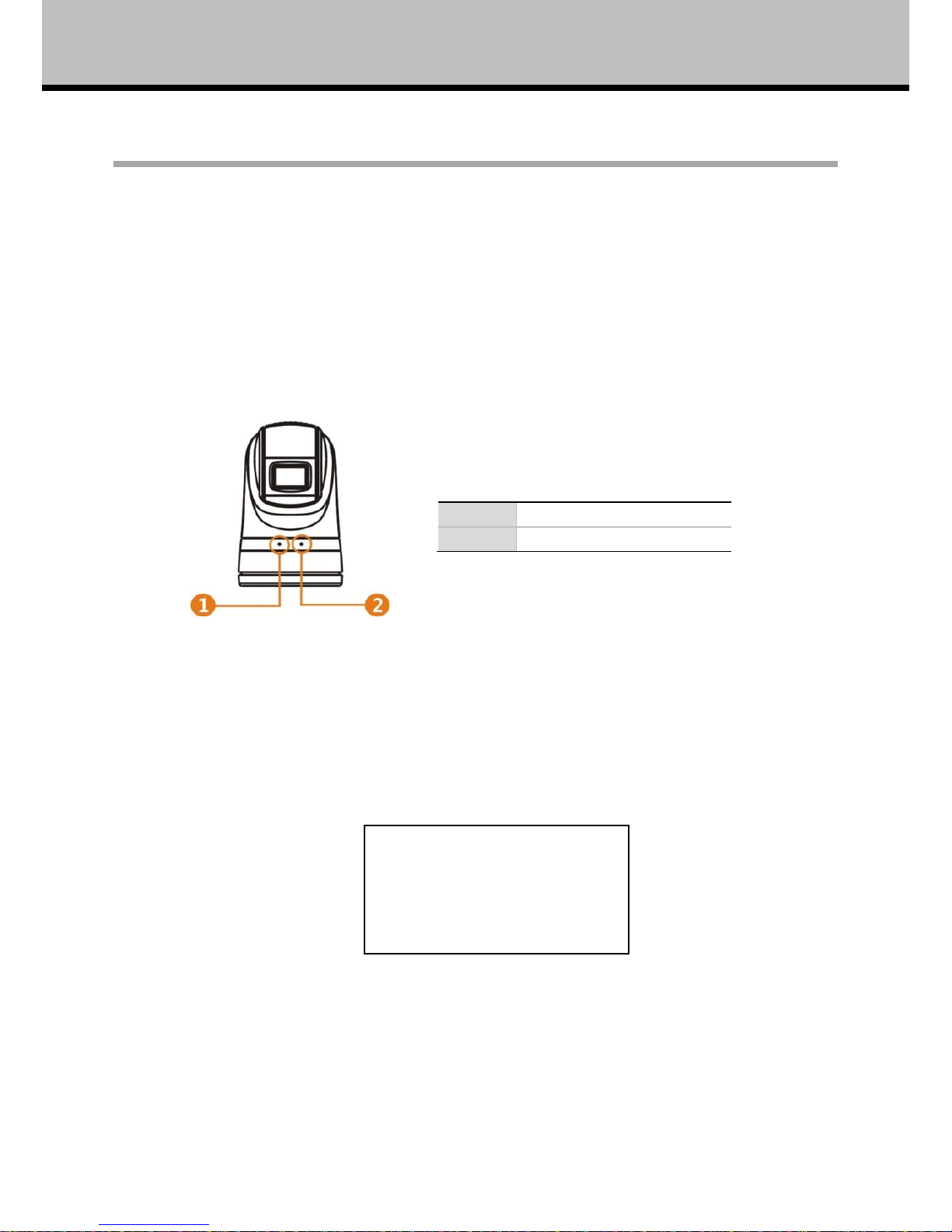
When the camera is powered on, the LED indicators at the front will be on.
1
Power (Constantly On)
2
Data (Flashing)
Fig. 2: LED Indicators
The camera will run a calibration procedure on power up and show the following messages on
screen.
Fig. 3: On Screen Messages at Power Up
If the camera fails at initialization, the following message will show on screen.
DOME ID:001
PROTOCOL:PELCO-D/P
BAUD:9600
SOFTWARE VER: 1.0.0
Page 14
Preparation
10
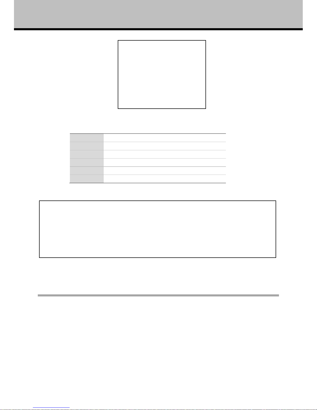
Please refer to the following code to check the failures:
PAN FAIL
Failure of pan initialization
TILT FAIL
Failure of tilt initialization
CAM FAIL
Failure of block camera initialization
P/T FAIL
Failure of pan and tilt initializations
T/Z FAIL
Failure of tilt and block camera initializations
P/T/Z FAIL
Failure of pan, tilt and block camera initializations
Installation Place
Make sure the installation place has enough space, support strength to install the whole PTZ
camera and its accessories.
[Note] In case of P/T failure:
If the ambient temperature is below 5℃, the heater will be turned on automatically
and the PTZ camera will do the initialization again.
If the ambient temperature is above 5℃, please reboot the PTZ camera.
DOME ID:001
PROTOCOL:PELCO-D/P
BAUD:9600
SOFTWARE VER: 1.0.0
CAM FAIL
Page 15
11
Installation
Fixed Mounts
The fixed mount provides damping system as optional.
Fig. 4: Fixed Mounts (with and w/o damping system)
Page 16
Installation
12
Installation
To set the baud rate, protocol and camera’s hard address:
1. Remove the PTZ bottom plate;
2. Set DIP Switch for baud rate, protocol and camera address;
3. Fix the bottom plate. Make sure the sealing is well installed.
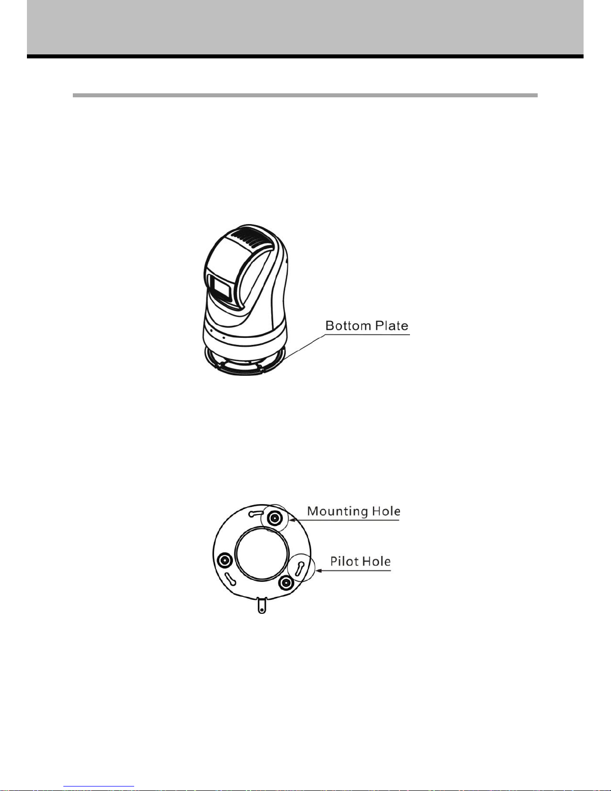
Fig. 5: Bottom Plate
4. Take the installation plate out of packing and fix it to the target place as per the plate
dimensions with correct screws.
Fig. 6: Installation Plate
5. Put the camera onto the installation plate. Make sure three installation bolts are in position with
the fixing holes on the plate. Rotate the camera clockwise.
6.
Page 17
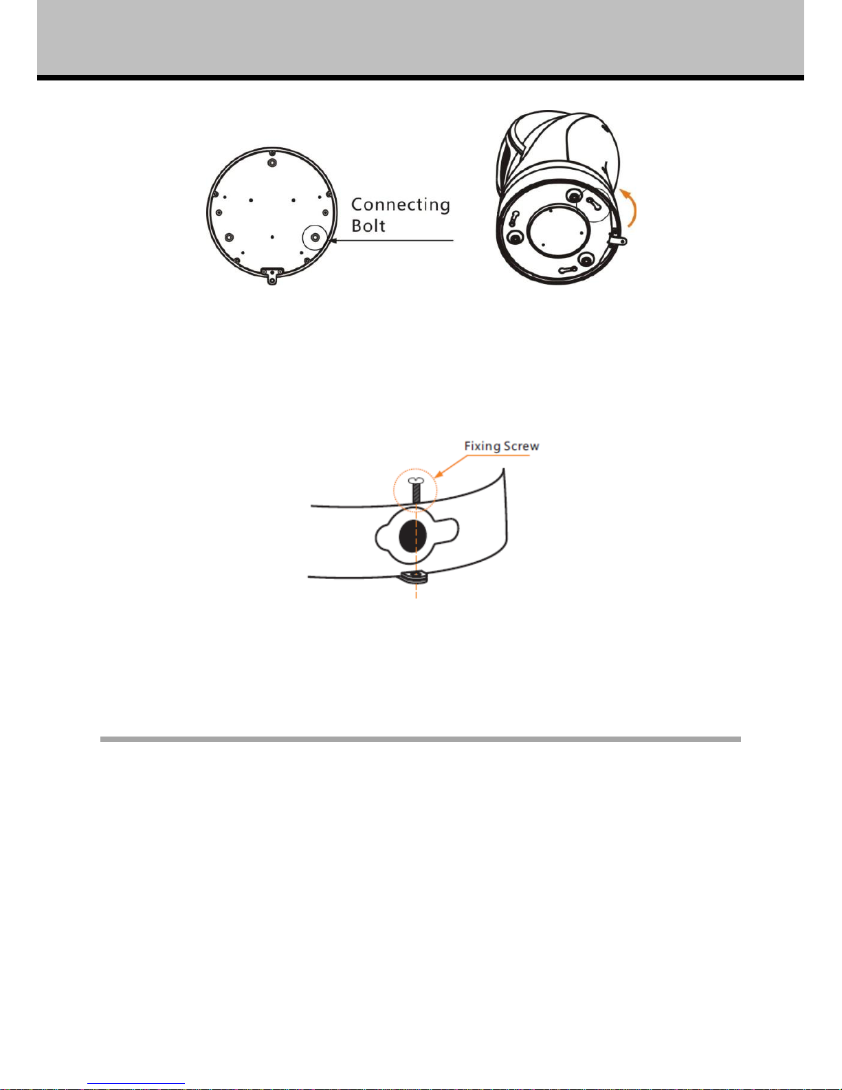
13
Installation
Fig. 7: Mount the Installation Plate
7. Fix the camera to the installation plate with a screw.
Fig. 8: Fix the Installation Plate
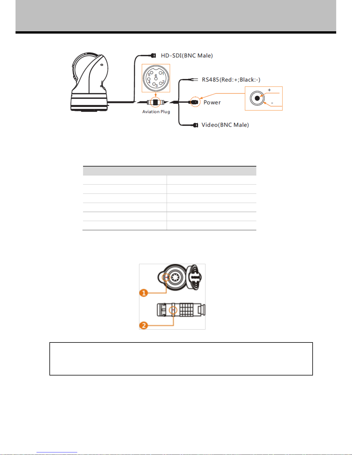
Camera Cable Package
Connect the cable with the right pins as per following pictures.
Page 18
Installation
14
Fig. 9: Cable Package
6Pin Cable: Pin Definition
1
Video +
2
Power -
3
Power +
4
RS485 -
5
RS485 +
6
Video -
There are two red marks each on the plug and socket. Please match them during plugging.
[Note] Please make sure the camera is working with a right power supply. Wrong cable
connection may cause damage to the device.
Page 19

15
MENU SETTINGS
Menu Configuration
<VIDEO>
Refer to
FORMAT
1080i50, 1080i60, 1080p25, 1080p30,
720p50, 720p60, 720p25, 720p30
Page 17
WIDE DYNAMIC
ON, OFF, AUTO
DNR
1, 2, 3, 4, 5, OFF
FOCUS
MANUAL , AUTO
FREEZE
ON, OFF
DIGI ZOOM
ON, OFF
DIS ON, OFF
EXPOSURE…
<PAN TILT>
Refer to
Page 19
LIGHT
ON, OFF
WIPER
OFF, NORMAL, FAST
DAY/NIGHT
AUTO, DAY, NIGHT
PRESET…
CRUISE…
FRAME SCAN…
RANDAM SCAN INTERVAL/S
4, 5, 6, 7, 8, 9, 10, 11, 12, 13
POWER UP ACTION
PRESET 1~9, NONE, HOME
PAN/TILT SPEED
1, 2, 3
<SYSTEM>
Refer to
Page 21
ADDRESS
0~255
PROTOCOL PELCO-D/P
BAUD RATE 9600
VIDEO FORMAT 1080i50
MOUNT MODE STAND
DISPLAY INFO
ON, OFF
SOFTWARE VER V1.0.0
<REBOOT> Refer to page 22
<RESTORE FACTORY DEFAULTS> Refer to page 22
Page 20
16
Menu settings
Menu Explanation
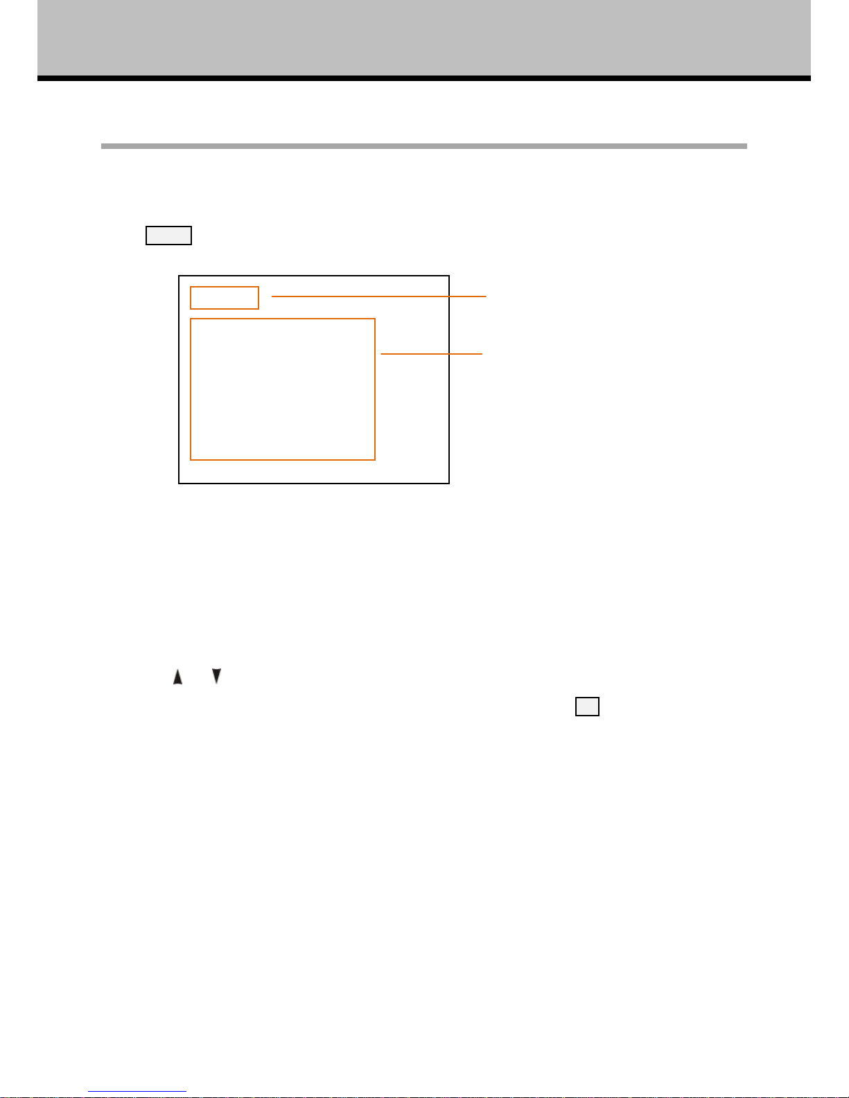
Main Menu
Press MENU button to enter / exit menu.
❶ Menu Title
It displays currently selected menu entries.
❷ Menu Entries
It displays options under current menu title.
Press or button to select among menu options, once font of options turned from white
color to yellow color, it indicates the menu has been elected, press OK button to get into this
menu.
<MENU>
VIDEO
PAN TILT
SYSTEM
REBOOT
RESTORE DEFAULTS
❶
❷
Page 21
17
Menu settings
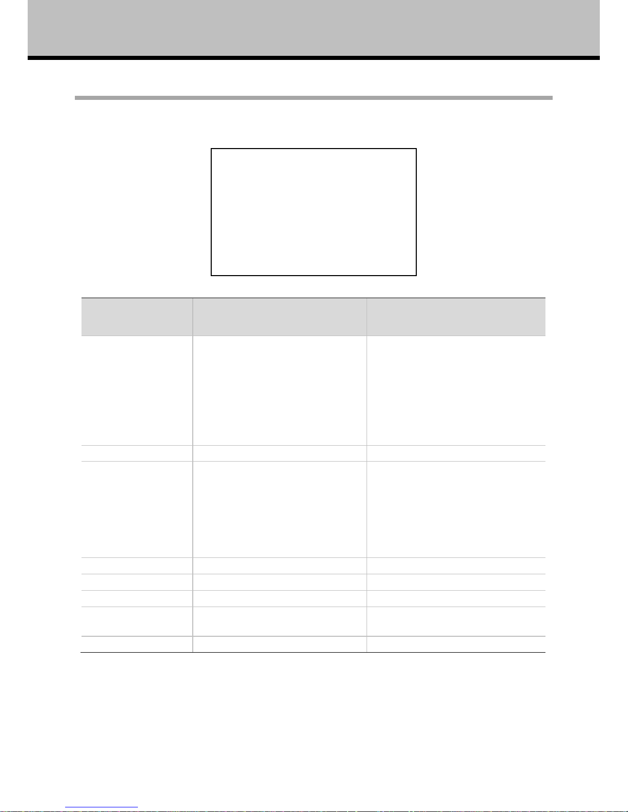
VIDEO
VIDEO menu is used to change video value.
Option
Value
Explanation
FORMAT
1080i50, 1080i60, 1080p25,
1080p30, 720p50, 720p60,
720p25, 720p30
When HD video output format is set
as 1080i60, 720p60, 1080p30,
720p30, relative SD video format is
NTSC;
When HD video output format is set
as 1080i50, 720p50, 1080p25,
720p25, relative SD video format is
PAL.
WIDE DYNAMIC
ON, OFF, AUTO
Switch wide dynamic mode.
DNR
1, 2, 3, 4, 5, OFF
If camera displays color image, it is
suggested to turn off the DNR level,
otherwise, the video trails will be
generated. The higher the level is, the
better is the noise reduction
performance, but more video trails
will be generated.
FOCUS
AUTO, MANUAL
Switch focus mode ON or OFF,
FREEZE
ON, OFF
Switch image freeze ON or OFF.
DIGI ZOOM
ON, OFF
Switch digital zoom ON or OFF.
DIS
ON, OFF
Switch digital image stabilization ON
or OFF.
EXPOSURE…
-
Automatic exposure submenu
<VIDEO>
FORMAT 1080P25
WIDE DYNAMIC OFF
DNR 5
FOCUS AUTO
FREEZE OFF
DIGI ZOOM OFF
DIS OFF
EXPOSURE…
Page 22
18
Menu settings
EXPOSURE
Option
Value
Explanation
MODE
FULL AUTO, MANUAL,
SHUTTER PRI, IRIS PRI
Switch exposure mode.
FULL AUTO: Gain, Shutter Speed and Iris value are adjusted automatically accordingly to working
environment.
SLOW SHT. LIMIT: this option sits under “Full Auto”, there are On and Off options.
MANUAL: manually adjust Gain, Shutter Speed and Iris
GAIN: -3, 0, +2, +4, +6, +8, +10, +12, +14, +16, +18, +20, +22, +24, +26, +28.
SPEED: 1/1, 1/2, 1/3, 1/6, 1/12, 1/25, 1/50, 1/75, 1/100, 1/120, 1/150, 1/215, 1/300, 1/425, 1/600,
1/1000, 1/1250, 1/1750, 1/2500, 1/3500, 1/6000, 1/10000s.
IRIS: F14, F11, F9.6, F8, F6.8, F5.6, F4.8, F4, F3.4, F2.8, F2.4, F2, F1.6, CLOSE.
SHUTTER PRI: Gain and Iris value are adjusted automatically according to working environment;
shutter speed value is adjustable manually.
SPEED: 1/1, 1/2, 1/3, 1/6, 1/12, 1/25, 1/50, 1/75, 1/100, 1/120, 1/150, 1/215, 1/300, 1/425, 1/600,
1/1000, 1/1250, 1/1750, 1/2500, 1/3500, 1/6000, 1/10000s.
IRIS PRI: Gain and shutter speed value are adjusted automatically according to working
environment; Iris value is adjustable manually.
IRIS: F14, F11, F9.6, F8, F6.8, F5.6, F4.8, F4, F3.4, F2.8, F2.4, F2, F1.6, CLOSE.
<EXPOSURE>
MODE FULL AUTO
SLOW SHT.LIMIT OFF
Page 23
19
Menu settings
PAN TILT
PAN/TILT is used to change pan/tilt/zoom value, available options:
Option
Value
Explanation
LIGHT
ON, OFF
This option sits under manual
DAY/NIGHT
WIPER
OFF, NORMAL, FAST
Default wiper setting is OFF.
DAY/NIGHT
AUTO, DAY, NIGHT
Switch DAY/NIGHT mode.
PRESET…
-
Preset parameter submenu
CRUISE…
-
Cruise parameter programming
submenu
FRAME SCAN…
-
Frame scan parameter programming
submenu.
RANDOM SCAN INTERVAL/S
4, 5, 6, 7, 8, 9, 10, 11, 12,
13
Setting interval of random scan.
POWER UP ACTION
PRESET 1~9, NONE, HOME
The action is performed after
powered up
PAN/TILT SPEED
1, 2, 3
Setting pan/tilt speed.
If preset 0 has been saved, after powered on, camera moves to preset 0 automatically; if
preset 0 has not been saved, after powered on, camera moves to Home position, where both
pan and tilt angle is zero and zooming time is 1x.
<PAN TILT>
LIGHT OFF
WIPER OFF
DAY/NIGHT AUTO
PRESET…
CRUISE…
FRAME SCAN…
RANDOM SCAN INTERVAL/S 6
POWER UP ACTION NONE
PAN/TILT SPEED 2
Page 24
20
Menu settings
PRESET
Option
Value
Explanation
NUM
0~255
Preset number
PAN
System information
Pan position
TILT
System information
Tilt position
ZOOM
System information
Zoom position
LABEL
System information
Preset label
EDIT
YES, NO
Edit preset
DELETE
YES, NO
Delete preset
<EDIT>:Point the cursor to the EDIT by moving the joystick vertically. Choose YES by moving the
joystick right, the instruction will pop up:
Press OPEN , moving up/down/left/right and zoom of the camera to set preset.
CRUISE
<CRUISE>
PATH 1
INTERVAL/S 6
SELECT PRESET TO CRUISE
2 3 4 5 7 8 9 10 12
^ ^ ^ ^ ^ ^
<PRESET EDIT>
CLICK IRIS OPEN CONFIRM
CLICK IRIS CLOSE CANCEL
<PRESET>
NUM 1
PAN
TILT
ZOOM
LABEL
EDIT NO
DELETE NO
Page 25
21
Menu settings
Option
Value
Explanation
PATH
1,2,3,4
-
INTERVAL/S
4~13s
Duration (in seconds) of the dwelling
time on each preset.
SELECT PRESET TO CRUISE
System information
This menu item is used to enable each of
the preset positions used in the cruise
cycle.
SELECT PRESET TO CRUISE: Move joystick to preset number, press OPEN, the symbol “^”under
the number will be disappeared, Indicating present preset is not available in the cruise cycle.
Press OPEN again, the symbol will appear.
FRAME SCAN
Option
Value
Explanation
INTERVAL/S
4~13s
Setting interval of frame scan.
EDIT
YES, NO
Edit the preset of frame scan.
DELETE
YES, NO
Delete the preset of frame scan.
SYSTEM
SYSTEM displays current camera’s address, protocol, baud rate, video format, mount mode and
software version number.
<SYSTEM>
ADDRESS 1
PROTOCOL PELCO-D/P
BAUD RATE 9600
VIDEO FORMAT 1080P30
MOUNT MODE STAND
DISPLAY INFO ON
SOFTWARE VER V1.0.0
<FRAME SCAN>
INTERVAL/S 1
EDIT NO
DELETE NO
Page 26
22
Menu settings
Option
Value
Explanation
ADDRESS
0~255
Reboot is necessary after switch.
PROTOCOL
System information
-
BAUDRATE
System information
-
VIDEO FORMAT
System information
-
MOUNT MODE
CEILING, STAND
-
DISPLAY INFO
ON, OFF
Show or hide the information of PTZ
SOFTWARE VER
System information
-
REBOOT
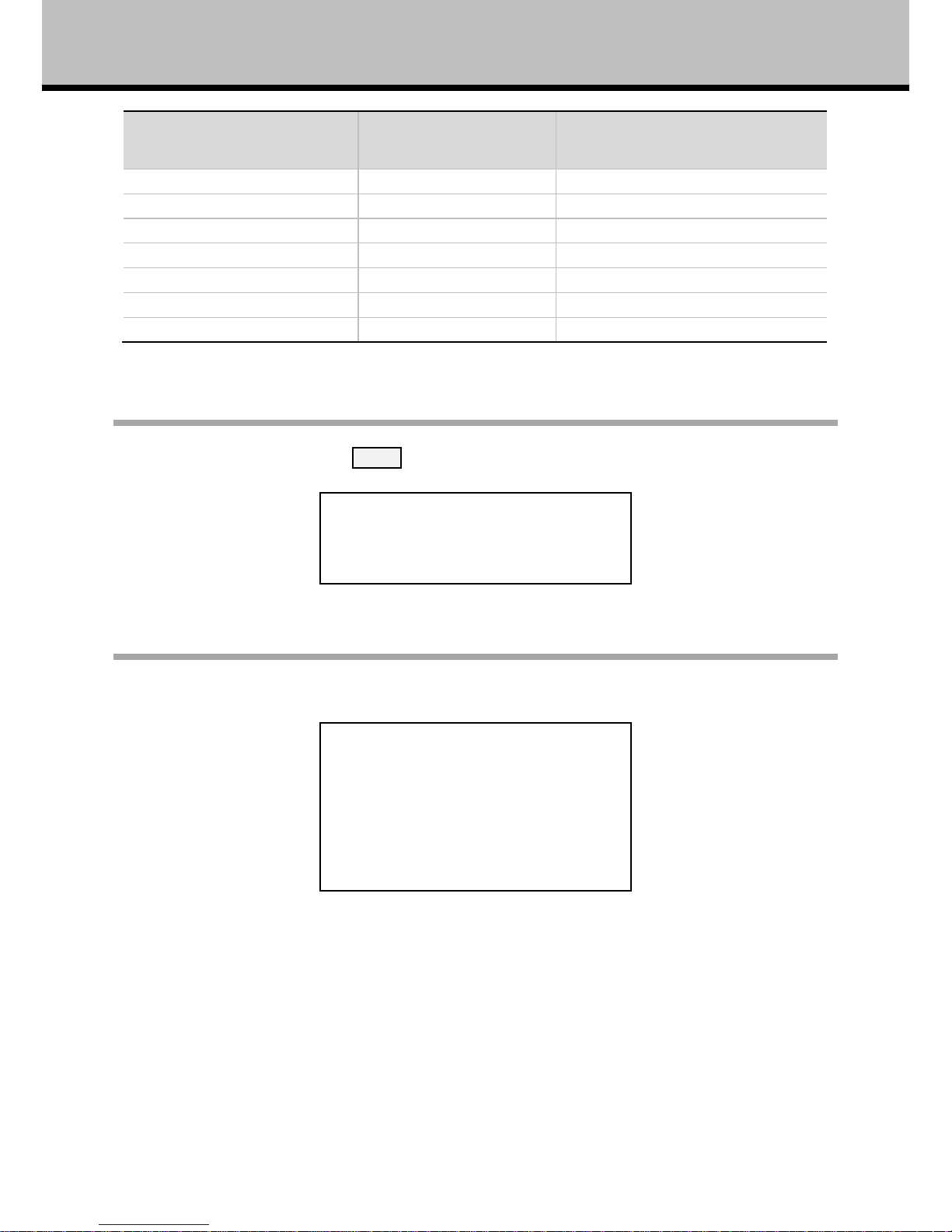
Choose REBOOT option, press OPEN to confirm, the indication will appear:
RESTORE FACTORY DEFAULTS
This menu is to resume the camera or all ptz parameters to factory default.
<RESTORE FACTORY DEFAULTS>
CLICK IRIS OPEN TO CONFIRM RESTORE
FAOTORY DEFAUIT
CLICK IRIS CLOSE TO CANCEL
<REBOOT>
CLICK IRIS OPEN TO CONFIRM
CLICK IRIS CLOSE TO CANCEL
Page 27

23
Operation
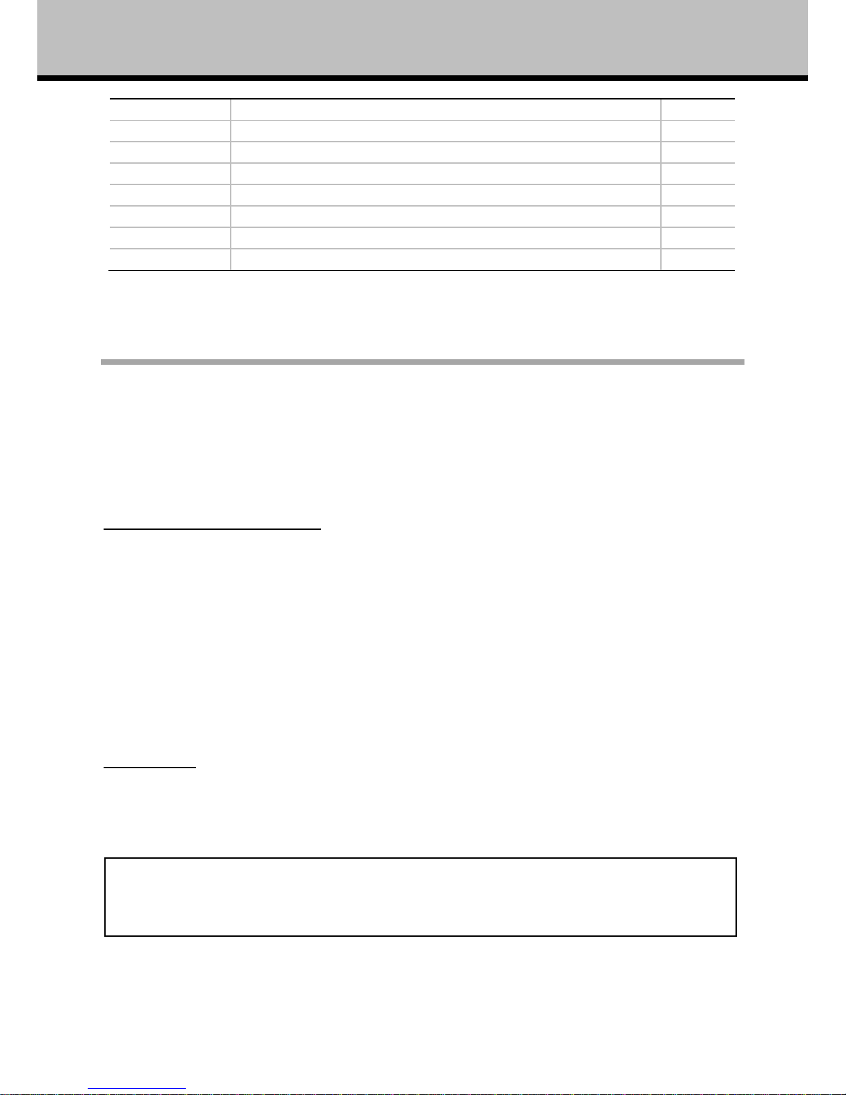
Special Control Panel Commands
The camera can be programmed and operated using various quick control panel commands.
Preset Number
Function
Default
Value
GO TO 21
Manual switch between color mode (with light off) and mono
mode (with light on)
***
GO TO 22
Auto switch between color mode (with IR off) and mono mode
(with IR on), for IR Version only
√
GO TO 23
Turn on/off Wide Dynamic Range (WDR)
Off
GO TO 24
Auto WDR
Off
GO TO 25
Turn on/off Back Light Compensation (BLC)
Off
GO TO 26
Turn on/off Image Flip
Off
GO TO 27
Turn on/off Digital Noise Reduction (DNR, 1-3/5steps)
Off
GO TO 28
Turn on/off video freeze
Off
GO TO 29
Turn on/off Digital Image Stabilization (DIS)
Off
GO TO 30
Turn on lights only (only for IR)
***
GO TO 31
Turn off lights only (only for IR)
√
GO TO 34
Fast wiper (Do not attempt to activate wiper when there is no
water on the glass)
***
GO TO 35
Normal wiper (Do not attempt to activate wiper when there is
no water on the glass)
***
GO TO 36
Turn off wiper
√
GO TO 37
Turn on defogger
***
GO TO 38
Turn off defogger
√
GO TO 39
Turn on/off digital zoom
Off
GO TO 40
Turn on/off on screen display
On
GO TO 42
Set Left Boundary Of Frame Scan
***
GO TO 43
Set Right Boundary Of Frame Scan
***
GO TO 48
Turn on random scan
***
GO TO 49
Turn on frame scan between two set presets
***
GO TO 50
Turn on cruise 1
***
GO TO 51
Turn on Auto Scan(360° Scan)
***
GO TO 52
Clear all Presets
***
GO TO 53
Restore factory default and reboot the camera
***
GO TO 57
Turn On/Off Screen Tips / Page Down Of Screen Tips
***
GO TO 59
PTZ Speed - Fast
***
GO TO 60
PTZ speed - Normal
√
GO TO 61
PTZ speed - Slow
***
GO TO 62
Decrease the camera Address By -1
***
GO TO 63
Increase the camera Address By +1
***
GO TO 64
Auto shutter
***
Page 28
24
Operation
GO TO 65
Increase the camera shutter speed
***
GO TO 66
Decrease the camera shutter speed
***
GO TO 67
Turn on cruise 2
***
GO TO 68
Turn on cruise 3
***
GO TO 69
Turn on cruise 4
***
GO TO 70
Turn on white lights only (only for white light models)
***
GO TO 71
Turn on white lights only (only for white light models)
√
GO TO 95
Enter menu
***
Table 2 Special Commands
Operation
As the baud rate and protocol are self-adaptive, the PTZ cameras may not response for seconds
on power up. It is recognizing the commands and adapting the setting.
IR / White Light
Auto Mode (For IR Version Only):
The default IR mode is auto. Auto mode can also be activated via preset 22. At this mode, the
commands of preset 30, 31 are disabled.
When the zoom module is in mono, the camera will automatically turn on IR lights. The high beam
and low beam will be turned on/off as per the current zoom times.
When the module is in color mode, the camera will automatically turn off IR lights.
Manual Mode:
Call Preset 21 to turn on the manual mode. The module will be switched into color or mono mode.
And lights can be controlled via the commands of presets 30, 31.
[Note] When the ambient temperature is above +50℃, the aux lighting system is suggested
to be turned off to protect the PTZ cameras.
Page 29
25
Operation
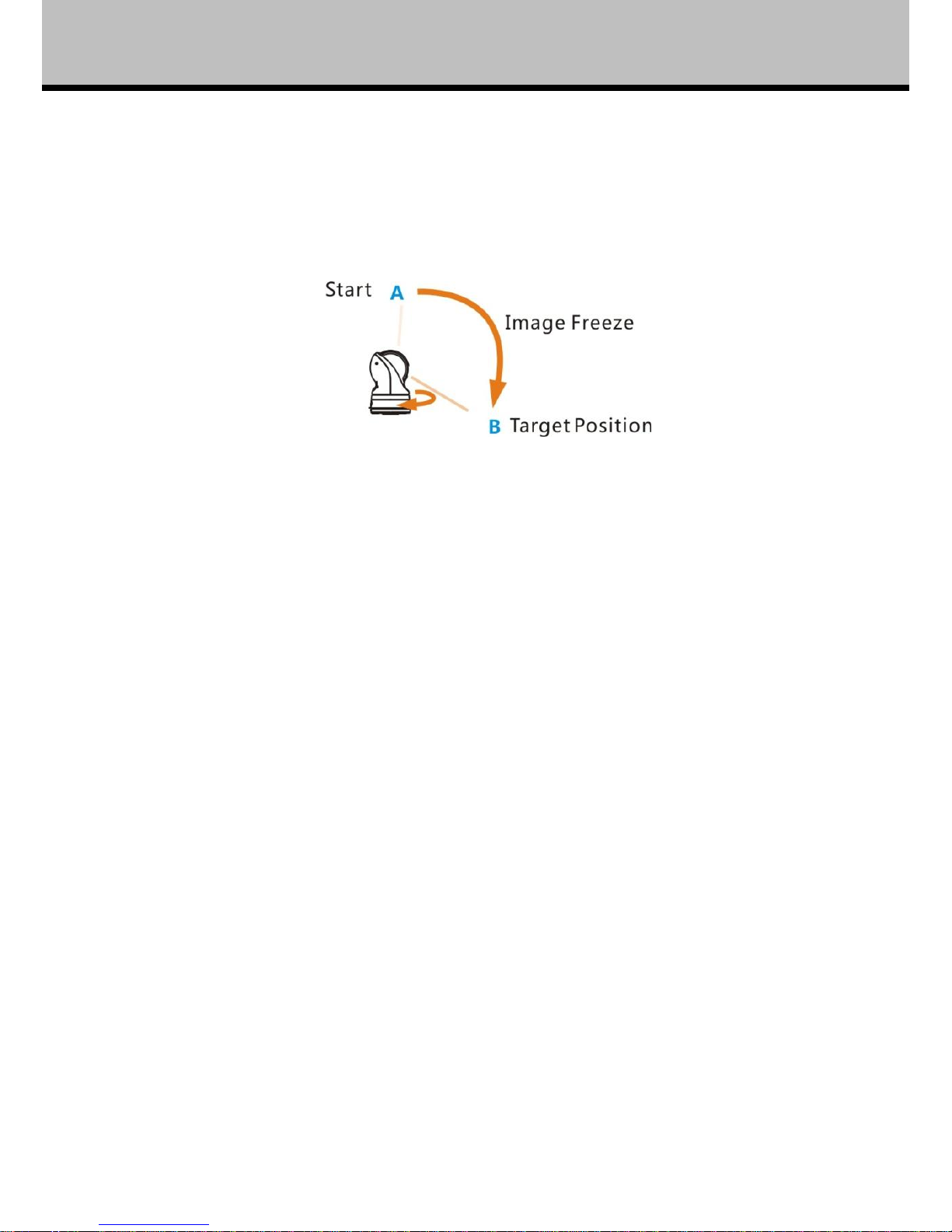
Image Freeze
Call Preset 28 to turn on/off the function. When it is on, during a regular preset call (see following
picture), the video will be frozen at point A till Point B. At Point B, the video will be displayed
normally.
Fig. 10: Image Freeze
Defogging
Call Preset 37 to turn on the function. There will be “DEFOGGING” flashing at top of the screen.
When the fog is cleared, turn off the function in time in case the camera temperature is getting too
high.
Call Preset 38 to turn off the function. The “DEFOGGING” at top of the screen will disappear from
the screen.
If the defogger is on, once temperature inside the camera reaches +55 degree, the defogger will be
turned off automatically;
If the defogger is off, once temperature inside the camera is lower than +10 degree, the defogger
will be turned on automatically.
Soft Address
The camera address can be changed via presets 62 and 63. The new address will take effect after
the camera is rebooted.
Page 30

26
Operation
Digital Image Stabilization (DIS)
The function is off as default. It can be turned on/off by calling preset 29.
It is used when the camera is used in a vibration environment, to compensate the vibration in video
(Some configuration does not support).
Digital Noise Reduction
The function is off as default.
When the camera is in color mode, it is recommended to turn off the function, or there will be video
trails.
When the camera is in mono mode, call preset 27 to turn on/off the function. There are 1~5 steps
from low to high. The higher the level is, the more video trails there are.
Wiper
For proper use of wiper, do not attempt to activate it when there is no water on the glass.
Page 31

27
Trouble Shooting
Problems
Possible Causes
Solutions
No action when powered
on
Power supply failure
Replace power supply
Wrong connection of the
power
Check & reconnect the cables
Abnormal self-test with
motor noise
Mechanical failure
Repair
Camera inclined
Reinstall the camera
Inadequate power supply
Replace the power supply
Normal self-test but no
images
Video signal failure
Reinstall camera
Wrong connection of the video
Check & reconnect the cables
Camera damaged
Replace the camera
Normal self-test but out of
control
Wrong connection of RS485
cable
Check and reconnect the
cable
Wrong camera address set
Check and reset the Switches
Vague image
Bad connection of the video
Check and reconnect the
cables
Inadequate power supply
Replace the power supply
PTZ camera out of control
Self test error
Restart the camera
Wrong connection of RS485
cable
Check and reconnect the
cables
Table 3 Trouble Shooting
Page 32

Annex: DIP Switch – Camera Address
28
ADDRESS
1 2 3 4 5 6 7
8
0
OFF
OFF
OFF
OFF
OFF
OFF
OFF
OFF 1 ON
OFF
OFF
OFF
OFF
OFF
OFF
OFF
2
OFF
ON
OFF
OFF
OFF
OFF
OFF
OFF 3 ON
ON
OFF
OFF
OFF
OFF
OFF
OFF
4
OFF
OFF
ON
OFF
OFF
OFF
OFF
OFF 5 ON
OFF
ON
OFF
OFF
OFF
OFF
OFF
6
OFF
ON
ON
OFF
OFF
OFF
OFF
OFF
7
ON
ON
ON
OFF
OFF
OFF
OFF
OFF 8 OFF
OFF
OFF
ON
OFF
OFF
OFF
OFF
9
ON
OFF
OFF
ON
OFF
OFF
OFF
OFF
10
OFF
ON
OFF
ON
OFF
OFF
OFF
OFF
11
ON
ON
OFF
ON
OFF
OFF
OFF
OFF
12
OFF
OFF
ON
ON
OFF
OFF
OFF
OFF
13
ON
OFF
ON
ON
OFF
OFF
OFF
OFF
14
OFF
ON
ON
ON
OFF
OFF
OFF
OFF
15
ON
ON
ON
ON
OFF
OFF
OFF
OFF
16
OFF
OFF
OFF
OFF
ON
OFF
OFF
OFF
17
ON
OFF
OFF
OFF
ON
OFF
OFF
OFF
18
OFF
ON
OFF
OFF
ON
OFF
OFF
OFF
19
ON
ON
OFF
OFF
ON
OFF
OFF
OFF
20
OFF
OFF
ON
OFF
ON
OFF
OFF
OFF
21
ON
OFF
ON
OFF
ON
OFF
OFF
OFF
22
OFF
ON
ON
OFF
ON
OFF
OFF
OFF
23
ON
ON
ON
OFF
ON
OFF
OFF
OFF
24
OFF
OFF
OFF
ON
ON
OFF
OFF
OFF
25
ON
OFF
OFF
ON
ON
OFF
OFF
OFF
26
OFF
ON
OFF
ON
ON
OFF
OFF
OFF
27
ON
ON
OFF
ON
ON
OFF
OFF
OFF
28
OFF
OFF
ON
ON
ON
OFF
OFF
OFF
29
ON
OFF
ON
ON
ON
OFF
OFF
OFF
30
OFF
ON
ON
ON
ON
OFF
OFF
OFF
31
ON
ON
ON
ON
ON
OFF
OFF
OFF
32
OFF
OFF
OFF
OFF
OFF
ON
OFF
OFF
33
ON
OFF
OFF
OFF
OFF
ON
OFF
OFF
34
OFF
ON
OFF
OFF
OFF
ON
OFF
OFF
35
ON
ON
OFF
OFF
OFF
ON
OFF
OFF
36
OFF
OFF
ON
OFF
OFF
ON
OFF
OFF
37
ON
OFF
ON
OFF
OFF
ON
OFF
OFF
38
OFF
ON
ON
OFF
OFF
ON
OFF
OFF
Page 33

29
ANNEX: DIP SWITCH – CAMERA ADDRESS
39
ON
ON
ON
OFF
OFF
ON
OFF
OFF
40
OFF
OFF
OFF
ON
OFF
ON
OFF
OFF
41
ON
OFF
OFF
ON
OFF
ON
OFF
OFF
42
OFF
ON
OFF
ON
OFF
ON
OFF
OFF
43
ON
ON
OFF
ON
OFF
ON
OFF
OFF
44
OFF
OFF
ON
ON
OFF
ON
OFF
OFF
45
ON
OFF
ON
ON
OFF
ON
OFF
OFF
46
OFF
ON
ON
ON
OFF
ON
OFF
OFF
47
ON
ON
ON
ON
OFF
ON
OFF
OFF
48
OFF
OFF
OFF
OFF
ON
ON
OFF
OFF
49
ON
OFF
OFF
OFF
ON
ON
OFF
OFF
50
OFF
ON
OFF
OFF
ON
ON
OFF
OFF
51
ON
ON
OFF
OFF
ON
ON
OFF
OFF
52
OFF
OFF
ON
OFF
ON
ON
OFF
OFF
53
ON
OFF
ON
OFF
ON
ON
OFF
OFF
54
OFF
ON
ON
OFF
ON
ON
OFF
OFF
55
ON
ON
ON
OFF
ON
ON
OFF
OFF
56
OFF
OFF
OFF
ON
ON
ON
OFF
OFF
57
ON
OFF
OFF
ON
ON
ON
OFF
OFF
58
OFF
ON
OFF
ON
ON
ON
OFF
OFF
59
ON
ON
OFF
ON
ON
ON
OFF
OFF
60
OFF
OFF
ON
ON
ON
ON
OFF
OFF
61
ON
OFF
ON
ON
ON
ON
OFF
OFF
62
OFF
ON
ON
ON
ON
ON
OFF
OFF
63
ON
ON
ON
ON
ON
ON
OFF
OFF
64
OFF
OFF
OFF
OFF
OFF
OFF
ON
OFF
65
ON
OFF
OFF
OFF
OFF
OFF
ON
OFF
66
OFF
ON
OFF
OFF
OFF
OFF
ON
OFF
67
ON
ON
OFF
OFF
OFF
OFF
ON
OFF
68
OFF
OFF
ON
OFF
OFF
OFF
ON
OFF
69
ON
OFF
ON
OFF
OFF
OFF
ON
OFF
70
OFF
ON
ON
OFF
OFF
OFF
ON
OFF
71
ON
ON
ON
OFF
OFF
OFF
ON
OFF
72
OFF
OFF
OFF
ON
OFF
OFF
ON
OFF
73
ON
OFF
OFF
ON
OFF
OFF
ON
OFF
74
OFF
ON
OFF
ON
OFF
OFF
ON
OFF
75
ON
ON
OFF
ON
OFF
OFF
ON
OFF
76
OFF
OFF
ON
ON
OFF
OFF
ON
OFF
77
ON
OFF
ON
ON
OFF
OFF
ON
OFF
78
OFF
ON
ON
ON
OFF
OFF
ON
OFF
Page 34

30
ANNEX: DIP SWITCH – CAMERA ADDRESS
79
ON
ON
ON
ON
OFF
OFF
ON
OFF
80
OFF
OFF
OFF
OFF
ON
OFF
ON
OFF
81
ON
OFF
OFF
OFF
ON
OFF
ON
OFF
82
OFF
ON
OFF
OFF
ON
OFF
ON
OFF
83
ON
ON
OFF
OFF
ON
OFF
ON
OFF
84
OFF
OFF
ON
OFF
ON
OFF
ON
OFF
85
ON
OFF
ON
OFF
ON
OFF
ON
OFF
86
OFF
ON
ON
OFF
ON
OFF
ON
OFF
87
ON
ON
ON
OFF
ON
OFF
ON
OFF
88
OFF
OFF
OFF
ON
ON
OFF
ON
OFF
89
ON
OFF
OFF
ON
ON
OFF
ON
OFF
90
OFF
ON
OFF
ON
ON
OFF
ON
OFF
91
ON
ON
OFF
ON
ON
OFF
ON
OFF
92
OFF
OFF
ON
ON
ON
OFF
ON
OFF
93
ON
OFF
ON
ON
ON
OFF
ON
OFF
94
OFF
ON
ON
ON
ON
OFF
ON
OFF
95
ON
ON
ON
ON
ON
OFF
ON
OFF
96
OFF
OFF
OFF
OFF
OFF
ON
ON
OFF
97
ON
OFF
OFF
OFF
OFF
ON
ON
OFF
98
OFF
ON
OFF
OFF
OFF
ON
ON
OFF
99
ON
ON
OFF
OFF
OFF
ON
ON
OFF
100
OFF
OFF
ON
OFF
OFF
ON
ON
OFF
101
ON
OFF
ON
OFF
OFF
ON
ON
OFF
102
OFF
ON
ON
OFF
OFF
ON
ON
OFF
103
ON
ON
ON
OFF
OFF
ON
ON
OFF
104
OFF
OFF
OFF
ON
OFF
ON
ON
OFF
105
ON
OFF
OFF
ON
OFF
ON
ON
OFF
106
OFF
ON
OFF
ON
OFF
ON
ON
OFF
107
ON
ON
OFF
ON
OFF
ON
ON
OFF
108
OFF
OFF
ON
ON
OFF
ON
ON
OFF
109
ON
OFF
ON
ON
OFF
ON
ON
OFF
110
OFF
ON
ON
ON
OFF
ON
ON
OFF
111
ON
ON
ON
ON
OFF
ON
ON
OFF
112
OFF
OFF
OFF
OFF
ON
ON
ON
OFF
113
ON
OFF
OFF
OFF
ON
ON
ON
OFF
114
OFF
ON
OFF
OFF
ON
ON
ON
OFF
115
ON
ON
OFF
OFF
ON
ON
ON
OFF
116
OFF
OFF
ON
OFF
ON
ON
ON
OFF
117
ON
OFF
ON
OFF
ON
ON
ON
OFF
118
OFF
ON
ON
OFF
ON
ON
ON
OFF
Page 35

31
ANNEX: DIP SWITCH – CAMERA ADDRESS
119
ON
ON
ON
OFF
ON
ON
ON
OFF
120
OFF
OFF
OFF
ON
ON
ON
ON
OFF
121
ON
OFF
OFF
ON
ON
ON
ON
OFF
122
OFF
ON
OFF
ON
ON
ON
ON
OFF
123
ON
ON
OFF
ON
ON
ON
ON
OFF
124
OFF
OFF
ON
ON
ON
ON
ON
OFF
125
ON
OFF
ON
ON
ON
ON
ON
OFF
126
OFF
ON
ON
ON
ON
ON
ON
OFF
127
ON
ON
ON
ON
ON
ON
ON
OFF
128
OFF
OFF
OFF
OFF
OFF
OFF
OFF
ON
129
ON
OFF
OFF
OFF
OFF
OFF
OFF
ON
130
OFF
ON
OFF
OFF
OFF
OFF
OFF
ON
131
ON
ON
OFF
OFF
OFF
OFF
OFF
ON
132
OFF
OFF
ON
OFF
OFF
OFF
OFF
ON
133
ON
OFF
ON
OFF
OFF
OFF
OFF
ON
134
OFF
ON
ON
OFF
OFF
OFF
OFF
ON
135
ON
ON
ON
OFF
OFF
OFF
OFF
ON
136
OFF
OFF
OFF
ON
OFF
OFF
OFF
ON
137
ON
OFF
OFF
ON
OFF
OFF
OFF
ON
138
OFF
ON
OFF
ON
OFF
OFF
OFF
ON
139
ON
ON
OFF
ON
OFF
OFF
OFF
ON
140
OFF
OFF
ON
ON
OFF
OFF
OFF
ON
141
ON
OFF
ON
ON
OFF
OFF
OFF
ON
142
OFF
ON
ON
ON
OFF
OFF
OFF
ON
143
ON
ON
ON
ON
OFF
OFF
OFF
ON
144
OFF
OFF
OFF
OFF
ON
OFF
OFF
ON
145
ON
OFF
OFF
OFF
ON
OFF
OFF
ON
146
OFF
ON
OFF
OFF
ON
OFF
OFF
ON
147
ON
ON
OFF
OFF
ON
OFF
OFF
ON
148
OFF
OFF
ON
OFF
ON
OFF
OFF
ON
149
ON
OFF
ON
OFF
ON
OFF
OFF
ON
150
OFF
ON
ON
OFF
ON
OFF
OFF
ON
151
ON
ON
ON
OFF
ON
OFF
OFF
ON
152
OFF
OFF
OFF
ON
ON
OFF
OFF
ON
153
ON
OFF
OFF
ON
ON
OFF
OFF
ON
154
OFF
ON
OFF
ON
ON
OFF
OFF
ON
155
ON
ON
OFF
ON
ON
OFF
OFF
ON
156
OFF
OFF
ON
ON
ON
OFF
OFF
ON
157
ON
OFF
ON
ON
ON
OFF
OFF
ON
158
OFF
ON
ON
ON
ON
OFF
OFF
ON
Page 36

32
ANNEX: DIP SWITCH – CAMERA ADDRESS
159
ON
ON
ON
ON
ON
OFF
OFF
ON
160
OFF
OFF
OFF
OFF
OFF
ON
OFF
ON
161
ON
OFF
OFF
OFF
OFF
ON
OFF
ON
162
OFF
ON
OFF
OFF
OFF
ON
OFF
ON
163
ON
ON
OFF
OFF
OFF
ON
OFF
ON
164
OFF
OFF
ON
OFF
OFF
ON
OFF
ON
165
ON
OFF
ON
OFF
OFF
ON
OFF
ON
166
OFF
ON
ON
OFF
OFF
ON
OFF
ON
167
ON
ON
ON
OFF
OFF
ON
OFF
ON
168
OFF
OFF
OFF
ON
OFF
ON
OFF
ON
169
ON
OFF
OFF
ON
OFF
ON
OFF
ON
170
OFF
ON
OFF
ON
OFF
ON
OFF
ON
171
ON
ON
OFF
ON
OFF
ON
OFF
ON
172
OFF
OFF
ON
ON
OFF
ON
OFF
ON
173
ON
OFF
ON
ON
OFF
ON
OFF
ON
174
OFF
ON
ON
ON
OFF
ON
OFF
ON
175
ON
ON
ON
ON
OFF
ON
OFF
ON
176
OFF
OFF
OFF
OFF
ON
ON
OFF
ON
177
ON
OFF
OFF
OFF
ON
ON
OFF
ON
178
OFF
ON
OFF
OFF
ON
ON
OFF
ON
179
ON
ON
OFF
OFF
ON
ON
OFF
ON
180
OFF
OFF
ON
OFF
ON
ON
OFF
ON
181
ON
OFF
ON
OFF
ON
ON
OFF
ON
182
OFF
ON
ON
OFF
ON
ON
OFF
ON
183
ON
ON
ON
OFF
ON
ON
OFF
ON
184
OFF
OFF
OFF
ON
ON
ON
OFF
ON
185
ON
OFF
OFF
ON
ON
ON
OFF
ON
186
OFF
ON
OFF
ON
ON
ON
OFF
ON
187
ON
ON
OFF
ON
ON
ON
OFF
ON
188
OFF
OFF
ON
ON
ON
ON
OFF
ON
189
ON
OFF
ON
ON
ON
ON
OFF
ON
190
OFF
ON
ON
ON
ON
ON
OFF
ON
191
ON
ON
ON
ON
ON
ON
OFF
ON
192
OFF
OFF
OFF
OFF
OFF
OFF
ON
ON
193
ON
OFF
OFF
OFF
OFF
OFF
ON
ON
194
OFF
ON
OFF
OFF
OFF
OFF
ON
ON
195
ON
ON
OFF
OFF
OFF
OFF
ON
ON
196
OFF
OFF
ON
OFF
OFF
OFF
ON
ON
197
ON
OFF
ON
OFF
OFF
OFF
ON
ON
198
OFF
ON
ON
OFF
OFF
OFF
ON
ON
Page 37

33
ANNEX: DIP SWITCH – CAMERA ADDRESS
199
ON
ON
ON
OFF
OFF
OFF
ON
ON
200
OFF
OFF
OFF
ON
OFF
OFF
ON
ON
201
ON
OFF
OFF
ON
OFF
OFF
ON
ON
202
OFF
ON
OFF
ON
OFF
OFF
ON
ON
203
ON
ON
OFF
ON
OFF
OFF
ON
ON
204
OFF
OFF
ON
ON
OFF
OFF
ON
ON
205
ON
OFF
ON
ON
OFF
OFF
ON
ON
206
OFF
ON
ON
ON
OFF
OFF
ON
ON
207
ON
ON
ON
ON
OFF
OFF
ON
ON
208
OFF
OFF
OFF
OFF
ON
OFF
ON
ON
209
ON
OFF
OFF
OFF
ON
OFF
ON
ON
210
OFF
ON
OFF
OFF
ON
OFF
ON
ON
211
ON
ON
OFF
OFF
ON
OFF
ON
ON
212
OFF
OFF
ON
OFF
ON
OFF
ON
ON
213
ON
OFF
ON
OFF
ON
OFF
ON
ON
214
OFF
ON
ON
OFF
ON
OFF
ON
ON
215
ON
ON
ON
OFF
ON
OFF
ON
ON
216
OFF
OFF
OFF
ON
ON
OFF
ON
ON
217
ON
OFF
OFF
ON
ON
OFF
ON
ON
218
OFF
ON
OFF
ON
ON
OFF
ON
ON
219
ON
ON
OFF
ON
ON
OFF
ON
ON
220
OFF
OFF
ON
ON
ON
OFF
ON
ON
221
ON
OFF
ON
ON
ON
OFF
ON
ON
222
OFF
ON
ON
ON
ON
OFF
ON
ON
223
ON
ON
ON
ON
ON
OFF
ON
ON
224
OFF
OFF
OFF
OFF
OFF
ON
ON
ON
225
ON
OFF
OFF
OFF
OFF
ON
ON
ON
226
OFF
ON
OFF
OFF
OFF
ON
ON
ON
227
ON
ON
OFF
OFF
OFF
ON
ON
ON
228
OFF
OFF
ON
OFF
OFF
ON
ON
ON
229
ON
OFF
ON
OFF
OFF
ON
ON
ON
230
OFF
ON
ON
OFF
OFF
ON
ON
ON
231
ON
ON
ON
OFF
OFF
ON
ON
ON
232
OFF
OFF
OFF
ON
OFF
ON
ON
ON
233
ON
OFF
OFF
ON
OFF
ON
ON
ON
234
OFF
ON
OFF
ON
OFF
ON
ON
ON
235
ON
ON
OFF
ON
OFF
ON
ON
ON
236
OFF
OFF
ON
ON
OFF
ON
ON
ON
237
ON
OFF
ON
ON
OFF
ON
ON
ON
238
OFF
ON
ON
ON
OFF
ON
ON
ON
Page 38

ANNEX: DIP SWITCH – CAMERA ADDRESS
239
ON
ON
ON
ON
OFF
ON
ON
ON
240
OFF
OFF
OFF
OFF
ON
ON
ON
ON
241
ON
OFF
OFF
OFF
ON
ON
ON
ON
242
OFF
ON
OFF
OFF
ON
ON
ON
ON
243
ON
ON
OFF
OFF
ON
ON
ON
ON
244
OFF
OFF
ON
OFF
ON
ON
ON
ON
245
ON
OFF
ON
OFF
ON
ON
ON
ON
246
OFF
ON
ON
OFF
ON
ON
ON
ON
247
ON
ON
ON
OFF
ON
ON
ON
ON
248
OFF
OFF
OFF
ON
ON
ON
ON
ON
249
ON
OFF
OFF
ON
ON
ON
ON
ON
250
OFF
ON
OFF
ON
ON
ON
ON
ON
251
ON
ON
OFF
ON
ON
ON
ON
ON
252
OFF
OFF
ON
ON
ON
ON
ON
ON
253
ON
OFF
ON
ON
ON
ON
ON
ON
254
OFF
ON
ON
ON
ON
ON
ON
ON
255
ON
ON
ON
ON
ON
ON
ON
ON
Table 4: DIP Switch – Camera Address
Page 39

Page 40

 Loading...