

Page 1

User Manual
www.ruggedcams.com
Toll-Free: 866-301-2288
Page 2

FCC Compliance Statement
Model Name:
Rugged HD, Vertex Vault, VidSafe – 960H – Channel 4 / 8 / 16
This device complies with Part 15 of the FC C Rules. Operation is Subject to the followi ng two conductions: (1)
this device may not cause harmful interference, and (2) this device must accept any interference received,
including interference that may cause undesired operations.
WARNING
Unauthorized reproduction of all or part of this manual is strictly prohibited.
The figures in this manual are for illustration purposes only (may differ from the actual product).
The specifications and design of the product are subj ect to change without prior notice for purposes of quality
improvement.
CAUTIONS
To get the best use out of the product, be sure to read the cautions before using the product. For safety, please
take note of the following.
Instructions before using the product
1 To prevent electric shock when ins talling, moving, or opening the DVR and peripheral devices, connect
and disconnect the cables as instructed. All cables must be connected to grounded power outlets.
2 If the product is installed near a power outlet, make sure it can be unplugged easily.
3 Do not use the DV R in water or in wet places.
4 Keep the plastic packing materials used for the DVR or other peripher al devices out of reach of ch ildren
(may cause suffocation).
Installation Environment of the DVR
1 Maintain the following con d it ion s : ope rating temperature of 5˚C ~ 40˚C; operating humidity of 10% ~ 80%.
2 Install the DVR in a safe place that is free from external vibration.
3 Install the DVR in a well-ventilated place.
4 To protect the hard disk from data loss and breakdown, install the DVR away from magnetic materials.
5 When using a rack other than the standard one, use a separate table with sufficient spacing, i.e., 60cm
from the floor, 50cm from the ceiling, and 20cm from the side and back walls and other objects.
Safety Notes on the DVR
1 When installing additional boards and HDD, separate the power cable and turn OFF power supplied to the
DVR completely..
2 Keep the product away from he at-generating devices such as heaters.
3 Do not use a damaged power cord.
4 To prevent problems due to magnetic interference and electric surge, use only grounded cables and
power outlets.
5 If the power cord is conne cted, do not touch the power unit. If the power cord is connected, electric current
is still flowing internally even af t e r the sw it ch is turne d OFF.
6 Do not place a heavy object on top of the product.
7 Do not drop a conductive object in the ventilation holes.
8 Allot sufficient spa c e for system cabling.
9 Use only the parts indicated in the manual. Do not disassemble, repair, or modify the product without
permission.
10 Incorrect system setup may cause malfunction.
11 Shut down the system normally as instructed in the manual .
1
Page 3
Safety Notes on the Lithium Battery
1 Replace lithium batteries as instructed to avoid danger.
2 Dispose used lithium batteries properly.
【Warning and Caution are indicated as follows.】
Possible injury or product damage.
Risk of minor injury or product damage.
Cautions for the usage of the product.
Information for the usage of the product.
2
Page 4

Chapter 1. Introduction ................................................................... 8
1-1 960H Series Major Features .................................................................... 8
1-2 Components ......................................................................................... 9
1-3 Product Introduction ............................................................................. 10
Chapter 2. Installation and connection ........................................... 11
2-1 Names and Features of Each Part .......................................................... 11
2-1-1 RUGGED HD-16CH Rear Panel ................................................................... 11
2-1-1 VERTEX VAULT-08CH Rear ....................................................................... 11
2-1-2 VERTEX VAULT-16CH Rear ....................................................................... 11
2-1-3 VID SAFE-04CH Rear ................................................................................ 12
2-1-4 VID SAFE-08CH Rear ................................................................................ 12
2-1-5 VID SAFE-16CH Rear ................................................................................ 12
2-2 Installation and Connection ................................................................... 13
2-2-1 Basic Connection ...................................................................................... 15
2-3 Connection of Other Devices ................................................................. 16
Chapter 3. Operation and Setup Tools ........................................... 19
3-1 Rugged HD Series Front Panel Button ..................................................... 19
3-2 Vertex Vault Front Panel Button .............................................................. 20
3-3 Vid Safe Front Panel Button ................................................................... 21
3-4 Rugged HD-16 Series Remote Controller ................................................ 22
3-5 Vid Safe / Vid Safe Series Remote Controller ........................................... 23
3-6 Mouse ................................................................................................. 23
3-7 Jog/Shuttle .......................................................................................... 24
Chapter 4. DVR Operation Setup ................................................... 25
4-1 Rugged HD Series Storage Installation .................................................... 25
4-2 Vertex Vault Storage Installation ............................................................. 27
4-3 Vid Safe Storage Installation .................................................................. 28
4-4 Power ON. ........................................................................................... 28
4-5 Storage Setup ...................................................................................... 29
4-6 Recording Setup .................................................................................. 29
4-7 Date/Time Setup .................................................................................. 29
4-8 Camera / TV Setup ............................................................................... 30
4-9 Display Setting and Other Setup ............................................................. 30
4-10 External Device Setup ........................................................................ 30
4-11 Search ............................................................................................. 30
4-12 Backup............................................................................................. 30
4-13 DVR Info. .......................................................................................... 30
Chapter 5. System Operation ........................................................ 31
5-1 Real Time Monitoring Mode and Icon ...................................................... 31
5-2 System Login ....................................................................................... 32
5-2-1 User Account and Authorization.................................................................... 32
5-2-2 Login ...................................................................................................... 32
5-2-3 Logout..................................................................................................... 33
5-3 Monitoring ........................................................................................... 33
5-3-1 Screen Divisio n and Auto Sequence .............................................................. 33
5-3-2 Channel Grouping ..................................................................................... 34
5-3-3 Spot ........................................................................................................ 34
5-3-4 Menu in Monitoring Mode ............................................................................ 35
5-3-5 Zoom ...................................................................................................... 35
5-3-6 Screen Control by using PTZ ....................................................................... 36
3
Page 5

5-4 System Information and Screen Setup Change ........................................ 38
5-4-1 System Information .................................................................................... 38
5-4-2 Screen Brightness/Contra st/Color/Saturation/Sharpen/Camera Adjustment ........... 38
5-4-3 Display Setting .......................................................................................... 39
5-4-4 Screen Saver............................................................................................ 39
5-5 Control ................................................................................................ 40
5-6 Search ................................................................................................ 40
5-6-1 Search Mode ............................................................................................ 40
5-6-2 Playback Menu ......................................................................................... 41
5-7 Calendar Search ................................................................................... 41
5-7-1 Search Mode ............................................................................................ 41
5-7-2 Year/Month/Day Selection ........................................................................... 41
5-7-3 Time Index ............................................................................................... 41
5-7-4 Event ...................................................................................................... 42
5-7-5 Multi-Channel Search ................................................................................. 42
5-7-6 Multi-Time Search ..................................................................................... 42
5-7-7 Multi-Day Search ....................................................................................... 42
5-7-8 List All ..................................................................................................... 43
5-8 POS Search ......................................................................................... 43
5-8-1 POS Search Mode ..................................................................................... 43
5-8-2 Year/Month/Day/Text/Time Selection ............................................................. 43
5-8-3 Search / Playback...................................................................................... 43
5-9 Playback ............................................................................................. 44
5-9-1 Play back and Playback Speed Control ........................................................... 44
5-9-2 Smart Search ........................................................................................... 45
5-9-3 POS Search ............................................................................................. 46
5-9-4 Calendar Search ....................................................................................... 46
5-9-5 MULTI TIME ............................................................................................. 46
5-9-6 MULTI DAY .............................................................................................. 46
5-9-7 MULTI CHANNEL...................................................................................... 47
5-9-8 Panorama Play ......................................................................................... 47
5-9-9 Event ...................................................................................................... 47
5-9-10 Backup ................................................................................................. 47
5-9-11 Screen Mode ......................................................................................... 47
5-10 Log Viewer ....................................................................................... 47
5-10-1 Log Type .............................................................................................. 48
5-10-2 System Log Viewer ................................................................................. 48
5-11 Recording ......................................................................................... 49
5-11-1 Recording Types .................................................................................... 49
5-11-2 Recording Setup .................................................................................... 49
5-11-3 Recording Status View ............................................................................ 49
5-12 Backup............................................................................................. 50
5-12-1 Backup in The Real-Time Monitoring Mode .................................................. 50
5-12-2 Backup in Search Mode ........................................................................... 50
5-12-3 Backup in Log Mode ............................................................................... 50
5-12-4 Backup in Playback Mode ........................................................................ 50
5-12-5 Common Backup Procedure ..................................................................... 51
5-13 Setup Backup ................................................................................... 51
5-14 Log Backup ...................................................................................... 52
5-15 Capture ............................................................................................ 53
Chapter 6. Setup ........................................................................ 54
6-1 Time ................................................................................................... 54
6-1-1 Time Sync ................................................................................................ 54
6-1-2 Date and Time .......................................................................................... 55
6-1-3 Standard Time Zone .................................................................................. 55
6-1-4 Auto Reboot ............................................................................................. 55
4
Page 6

6-2 Camera ............................................................................................... 56
6-2-1 Camera ................................................................................................... 56
6-2-2 PTZ ........................................................................................................ 56
6-2-3 POS ....................................................................................................... 56
6-2-4 Event Source ............................................................................................ 56
6-2-5 Relay ...................................................................................................... 57
6-3 Recording ............................................................................................ 57
6-3-1 Schedule Selection (Schedule1 ~ Schedule4) ................................................. 58
6-3-2 Event ...................................................................................................... 58
6-3-3 Recording ................................................................................................ 58
6-3-4 Alarm ...................................................................................................... 59
6-3-5 Duration .................................................................................................. 59
6-3-6 Log ......................................................................................................... 59
6-4 Schedule ............................................................................................. 59
6-4-1 Schedule Setup......................................................................................... 59
6-5 Storage ............................................................................................... 60
6-5-1 Max. Recording Days ................................................................................. 60
6-5-2 HDD Overwrite.......................................................................................... 60
6-5-3 Local Storage Management ......................................................................... 60
6-6 Network ............................................................................................... 62
6-6-1 Ethernet .................................................................................................. 62
6-6-2 DDNS ..................................................................................................... 62
6-6-3 Port ........................................................................................................ 63
6-6-4 E-mail ..................................................................................................... 63
6-6-5 Bandwidth ................................................................................................ 65
6-6-6 iSCSI ...................................................................................................... 65
6-7 System ................................................................................................ 66
6-7-1 DVR Name ............................................................................................... 67
6-7-2 ID for Remote Controller ............................................................................. 67
6-7-3 ID For Keyboard Controller .......................................................................... 67
6-7-4 User Registration ....................................................................................... 68
6-7-5 Admin. Password ...................................................................................... 68
6-7-6 Upgrade .................................................................................................. 68
6-7-7 Factory Default ......................................................................................... 69
6-7-8 Console / POS Port.................................................................................... 69
6-7-9 Alarm ...................................................................................................... 69
6-7-10 Alarm Duration ....................................................................................... 69
6-7-11 Menu Time Out ...................................................................................... 69
6-7-12 Language ............................................................................................. 70
A/P/P/E/N/D/I/X ............................................................................ 71
Recommended PTZ Camera Protocol .............................................. 71
5
Page 7
[Figure 2-1. RUGGED HD-16CH Basic Connection and Device Connection] ................................ 13
[Figure 2-2. VERTEX VAULT-08CH Basic Connection and Device Connection] ............................ 13
[Figure 2-3. VERTEX VAULT-16CH Basic Connection and Device Connection] ............................ 14
[Figure 2-4. VID SAFE-04CH Basic Connection and Device Connection] ..................................... 14
[Figure 2-5. VID SAFE-08CH Basic Connection and Device Connection] ..................................... 15
[Figure 2-6. VID SAFE-16CH Basic Connection and Device Connection] ..................................... 15
[Figure 2-7. RUGGED HD-16CH Terminal Block and Description] .............................................. 17
[Figure 2-8. VERTEX VAULT-08 Terminal Block and Description] .............................................. 17
[Figure 2-9. VERTEX VAULT-16 Terminal Block and Description] .............................................. 17
[Figure 2-10. Vid Safe Series Terminal Block and Description] .................................................. 18
[Figure 4-11. Menu Window] .............................................................................................. 28
[Figure 5-12. Recordin g Status Window] ............................................................................... 31
[Figure 5-13. Login Window] ............................................................................................... 32
[Figure 5-14. 960H Model 16CH Channel Mode] .................................................................... 33
[Figure 5-15. 960H Model 8CH Channel Mode] ...................................................................... 33
[Figure 5-16. 960H Model 4CH Channel Mode] ...................................................................... 33
[Figure 5-17. Spot] ........................................................................................................... 35
[Figure 5-18. Zoom Control Screen] ..................................................................................... 36
[Figure 5-19. PTZ Setup] ................................................................................................... 36
[Figure 5-20. PTZ Control] ................................................................................................. 37
[Figure 5-21. PTZ Control Mini/Full] ..................................................................................... 37
[Figure 5-22. Product Information Window] ............................................................................ 38
[Figure 5-23. Screen Setup Window] .................................................................................... 38
[Figure 5-24. Display Se tting Window] .................................................................................. 39
[Figure 5-25. Display Se tting Window] .................................................................................. 39
[Figure 5-26. Audio] [Figure 5-27 . Relay] ..................................... 40
[Figure 5-28. Text] ............................................................................................................ 40
[Figure 5-29. Playback Menu] ............................................................................................. 40
[Figure 5-30. Search Window] ............................................................................................ 41
[Figure 5-31. Time Index] ................................................................................................... 43
[Figure 5-32. POS Search] ................................................................................................. 43
[Figure 5-33. Playback Screen] ........................................................................................... 44
[Figure 5-34. Playback Status and Control Window] ................................................................ 44
[Figure 5-35. Playback Menu] ............................................................................................. 45
[Figure 5-36. Smart Search Area Designation] ....................................................................... 46
[Figure 5-37. Smart Search Motion Detection Window] ............................................................ 46
[Figure 5-38. Panorama Playback] ....................................................................................... 47
[Figure 5-39. Display Mode] ............................................................................................... 47
[Figure 5-40. Log View] ..................................................................................................... 48
[Figure 5-41 . Move to the log list of the certain time zone in Log View] ....................................... 49
[Figure 5-42. Backup Window] ............................................................................................ 51
[Figure 5-43. Backup and Sub-menu Setup Backup] ............................................................... 52
[Figure 5-44. Setup Upgrade] ............................................................................................. 52
[Figure 5-45. Log Backup] .................................................................................................. 52
[Figure 6-46. Setup / Time Menu] ........................................................................................ 54
[Figure 6-47. Setup / Auto Reboot Menu] .............................................................................. 55
[Figure 6-48. Setup / Camera Menu] .................................................................................... 56
[Figure 6-49. Motion Area Setup] ......................................................................................... 57
[Figure 6-50. Setup / Recording] ......................................................................................... 57
[Figure 6-51. Schedule Wi ndow] ......................................................................................... 59
6
Page 8

[Figure 6-52. Storage Window (Local)] ................................................................................. 60
[Figure 6-53. Setup Network Window] .................................................................................. 62
[Figure 6-54. Network Port Window] ..................................................................................... 63
[Figure 6-55. Setup Network Ethernet Window] ...................................................................... 64
[Figure 6-56. Setup Network E-Mail Window1] ....................................................................... 64
[Figure 6-57. Setup Network E-Mail Window2] ....................................................................... 64
[Figure 6-58. Setup iSCSI Window1] .................................................................................... 65
[Figure 6-59. Setup iSCSI Window2] .................................................................................... 66
[Figure 6-60. System Setup Window] ................................................................................... 66
[Figure 6-61. Firmware Upgrad e Progressing Window] ............................................................ 68
7
Page 9
Chapter 1. Introduction
1-1 960H Series Major Features
System
Video
Audio
Video
Recording
Audio
Recording
Network
Backup
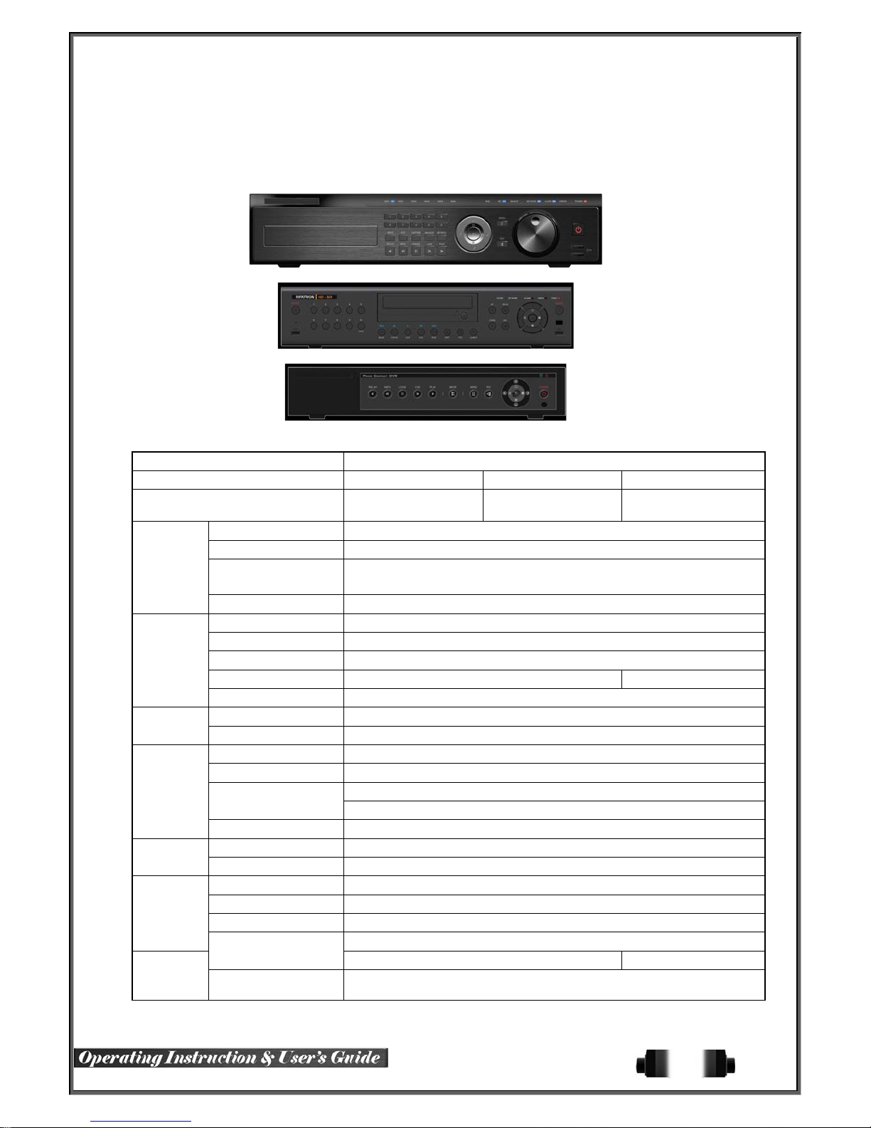
Line Up 960H DVR
Series Rugged HD Vertex Vault Vid Safe
Model Name RUGGED HD-16 VERTEX VAULT-08/16 VID SAFE-04/08/16
OS Embedded Linux - Built in flash memory
Access Front button, Mouse, Remote Controller, Network, Key controller
Hexaplex
Upgrade USB2.0 Memory stick, Network
System NTSC / PAL - Config switch
Input 16, 8, 4 BNC
Output 1 HDMI, 1 VGA, 1 BNC
Loop 16, 8 BNC N/A
Spot ★ 1 BNC - Multi-channel (16/9/4/1)
Input 16, 8, 4 RCA
Output HDMI, RCA
Compression H.264
Speed 960H real-time
Resolution ★ 960H (960x480/576)
Event Sensor, Motion, Audio
Bit Rate 1 ~ 5Mbps/Ch, Adjustable
Compression G.711U
Audio Sampling Rate 16KHz
Interface Ethernet 10/100/1G
Compression H.264
Speed Max. Q960H 8fps/ch
Resolution Max. 960H
Interface USB2.0, DVD, Network USB2.0, Network
Format
Live monitoring, Recording, Playback,
Backup, Network, Setup
Video clip (Backup viewer), JPEG Still Image
Log list, Setup data
8
Page 10
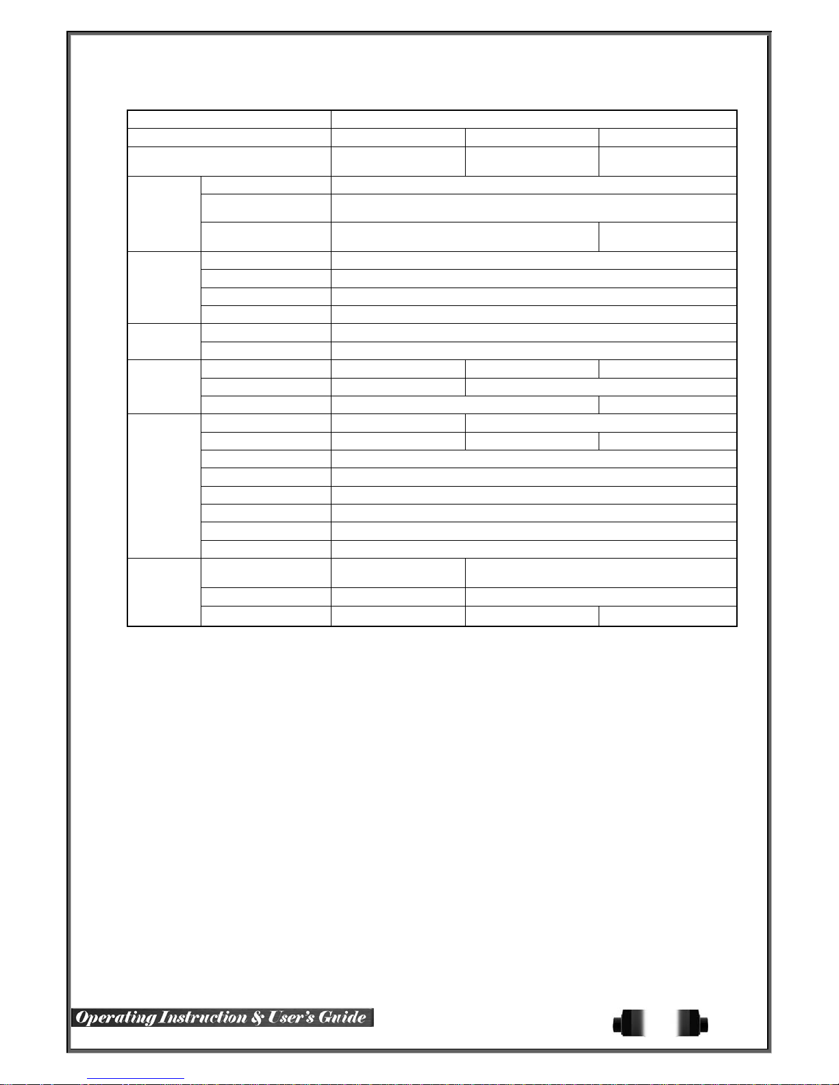
Line Up 960H DVR
Series Rugged HD Vertex Vault Vid Safe
Model Name RUGGED HD-16 VERTEX VAULT-08/16 VID SAFE-04/08/16
Pre/Post-Alarm 5sec / 5sec~5min
Alarm
Display
External
Interface
Storage
Features
Alarm Action
Input / Output 16/4, 8/2 - NC/NO/EOL 4/1, 4/1, 4/1 - NC/NO/EOL
HDMI ★ Full HD, XGA
VGA Full HD, XGA
TV SDTV(720x480/576)
Mode 16/9/4/1/SEQ - LIVE, 16/9/4/1 - P.B
PTZ / Keyboard ★ 2 RS485 - Terminal Block
ATM / POS
Primary 6 HDD 3 HDD 2 HDD
External 2 eSATA 1 eSATA
ODD 1 DVD N/A
Jog-shuttle Yes N/A
H/W RAID ★ RAID5 Options ★ RAID1 Options N/A
EOL Register(10K)
Coaxitron ★ Yes
DDNS, DHCP, UPNP Yes
CMS, VMS, RMS Windows
Smart Phone (3G) Android, iPhone, iPad
Mac Viewer ★ Apple Mac OS
E-mail, Channel Popup, Buzzer, Relay,
PTZ Preset, Spot, Remote CMS, Front LED
★ RS232C - Terminal Block
★ 4Ch
Power Supply 90~250V, 50/60Hz 12V/5A - Level 5
General
Consumption 80Watts 60Watts
Dimension 440 x 88 x 430 mm 430 x 86 x 270 mm 340 x 59 x 300 mm
1-2 Components
After unpacking the product, check whether following accessories are included.
- Remote Controller
- CD (CMS, CMS Manual, User Manual)
- AAA 1.5V Batteries 2ea
- Quick Service Guide
- Rack Mount Handle (Only for Rugged HD, Ve rtex Vault)
9
Page 11
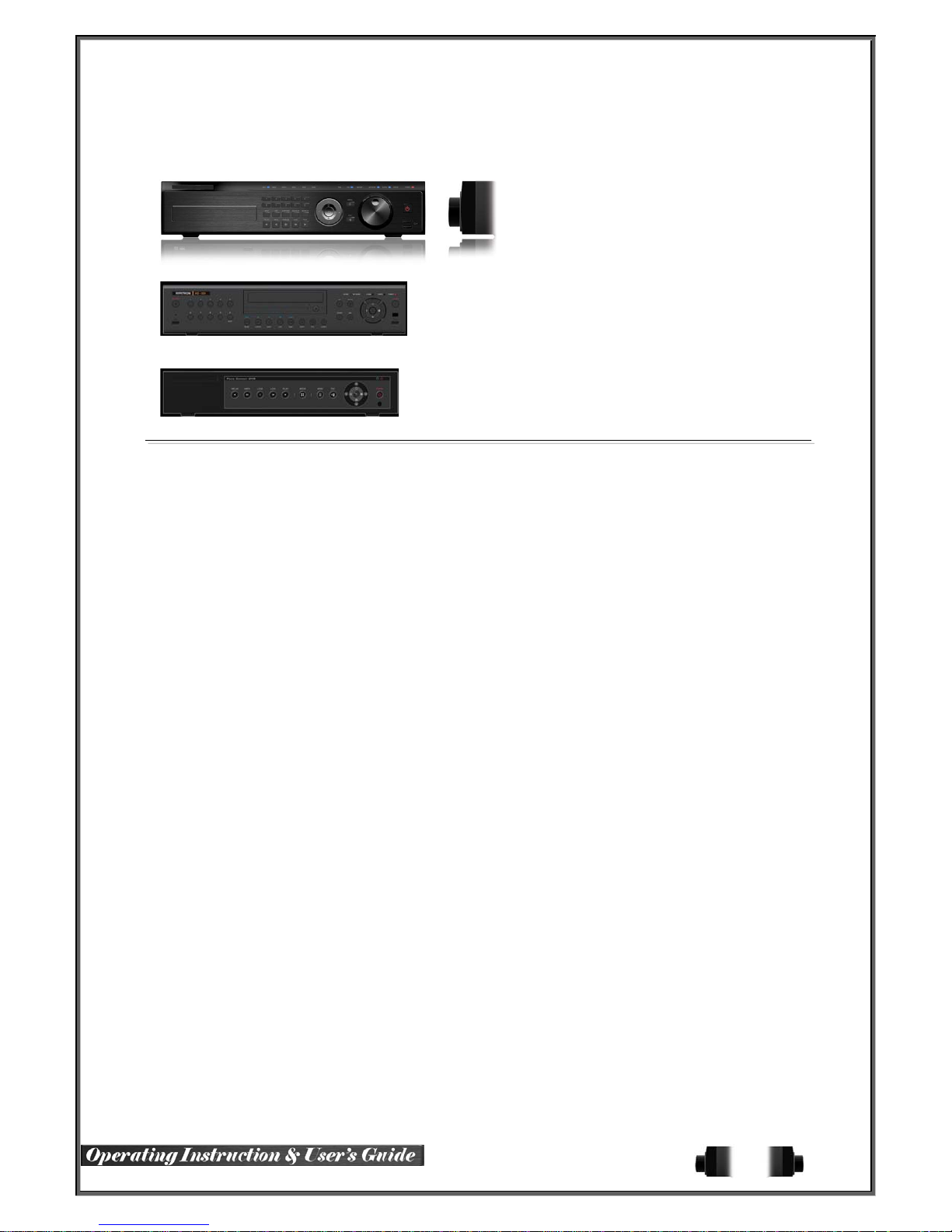
1-3 Product Introduction
960H real-time recording
16Ch audio recording
1Ch spot output
Various video output port (HDMI, VGA, BNC)
Various video output mode (Full HD, WSXGA+, SXGA, SDTV)
6 HDD bay (RUGGED HD-16 Model)
Jog-shuttle
1Ch POS/ATM interface
Pre-alarm recording
Auto e-mailing notification max. 5 users
Privacy zone mask
Covert channel
Digital single/multi-zoo m
Smart search
Text detection/search
Multi-time/day, Index (event) search/playback
Panorama playback
Data backup to NAS over Ethernet
Still image capture Full HD resolution
Firmware upgrade at a remote PC site
Remote setup, backup, relay control
Screen Saver
USB/DVD backup with self-executable player (backup player)
Web monitoring in PC (Built in web server)
Smart Phone viewer (Android, iOS)
Mobile web viewer (3G viewer)
NTP, DST , DDNS, DHCP
10
Page 12

Chapter 2. Installation and connection
2-1 Names and Features of Each Part
2-1-1 RUGGED HD-16CH Rear Panel
2-1-1 VERTEX VAULT-08CH Rear
2-1-2 VERTEX VAULT-16CH Rear
11
Page 13
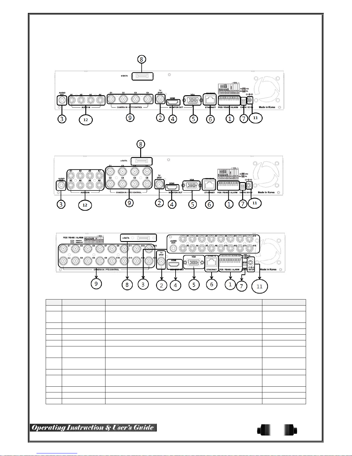
V
2-1-3 VID SAFE-04CH Rear
2-1-4 VID SAFE-08CH Rear
2-1-5 VID SAFE-16CH Rear
No. Name Feature Type
1 Terminal Block RS-485 / SENSOR IN / RELAY OUT / POS Terminal Block
2 SPOT / TV
3 AUDIO OUT Audio Output Connection(Line Only Output) RCA
4 HDMI HDMI Output HDMI type-C
5 VGA-OUT VGA Monitor or LCD Monitor Connection D-SUB 15P
6 Ethernet Cable Modem, Ethernet 10/100 Base-T, Network Connection RJ-45
7 CONFIG
8 e-SATA External SATA
9 CAMERA IN V ideo Camera Connection BNC
entilating
10
Opening
11 Power 90 ~ 250V, 50/60Hz, 80 Watts (H-model series) AC Inlet
12 AUDIO IN Audio Input Connection RCA
13 LOOP OUT Video Signal loop-back Output Connection BNC
CCTV monitor connection to output images of the channel generating
an event signal
NTSC/PAL
HD / XGA
BNC
DIP S/W, 2-pin
USB Type A,
e-SATA
Power supply
Fan
12
Page 14
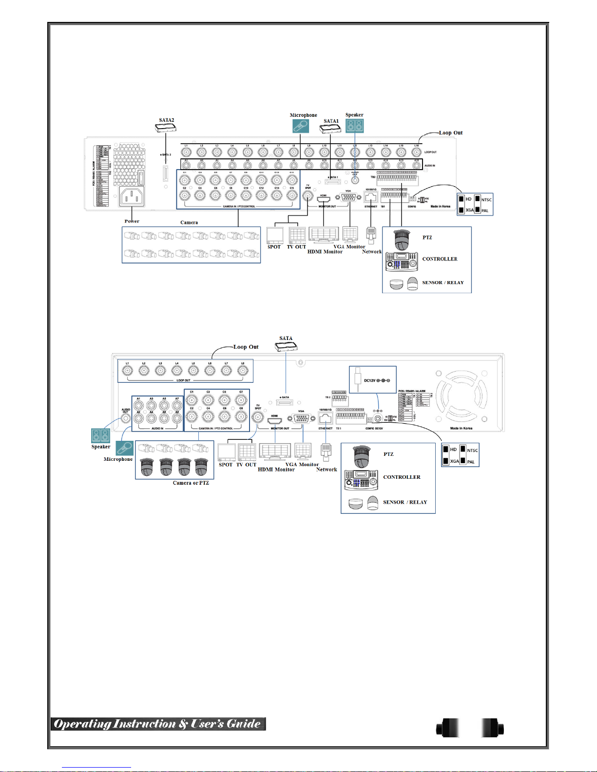
2-2 Installation and Connection
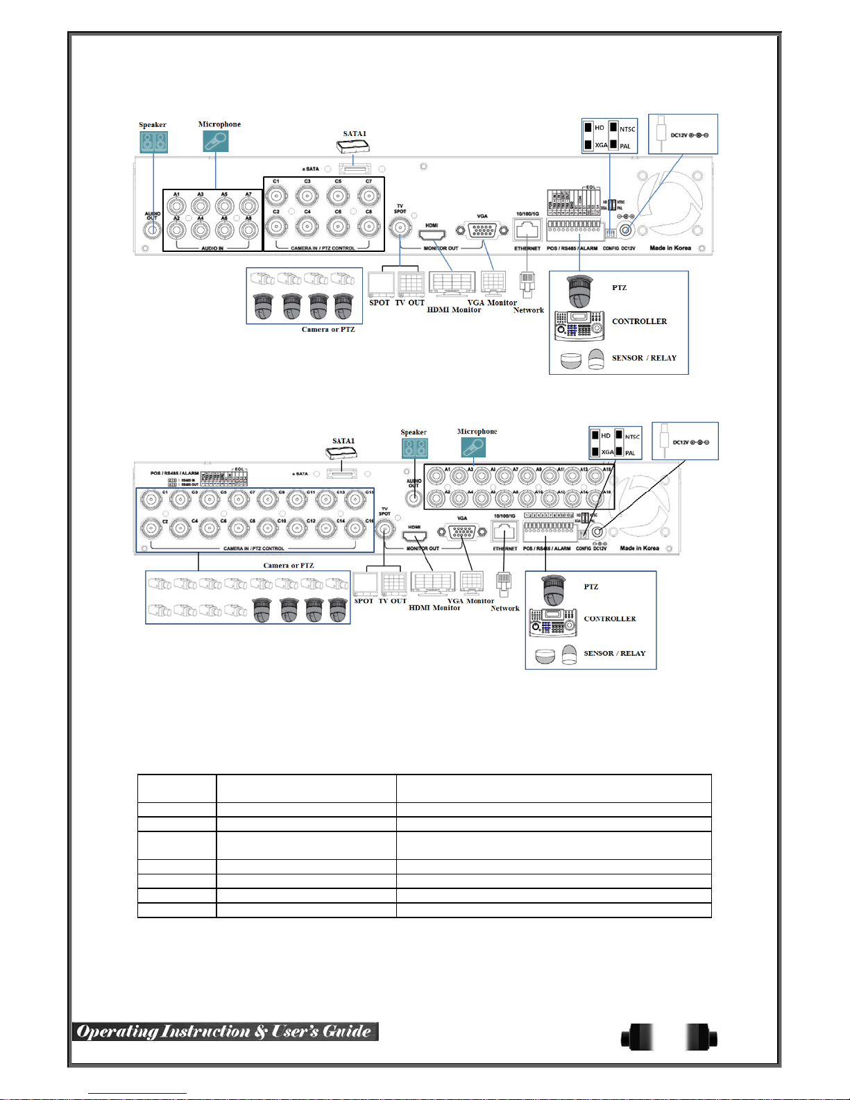
[Figure 2-1. RUGGED HD-16CH Basic Connection and Device Connection]
[Figure 2-2. VERTEX VAULT -08CH Basic Connection and Device Connection]
13
Page 15
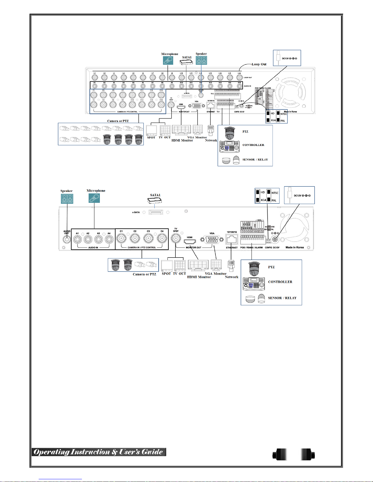
[Figure 2-3. VERTEX VAULT -16CH Basic Connection and Device Connection]
[Figure 2-4. VID SAFE-04CH Basic Connection and Device Connection]
14
Page 16
V
[Figure 2-5. VID SAFE-08CH Basic Connection and Device Connection]
[Figure 2-6. VID SAFE-16CH Basic Connection and Device Connection]
2-2-1 Basic Connection
※ By referring to above [Figure 2-1], make a connection accordingly.
Connection
Order
1 CCTV Camera Rear Panel Video IN
2 CCTV Audio Rear Panel Audio IN / OUT
2 CONFIG SWITCH Setup
3 CCTV Monitor Rear Panel TV/ SPOT
4
5 HDMI Monitor Rear Panel HDMI
6 Loop Rear Panel Loop
Connection Device DVR Terminal
Rear Panel Left 2ea Switch
(Refer to below; CONFIG SWITCH Setup)
GA Monitor / LCD Monitor Rear Panel VGA-OUT
15
Page 17
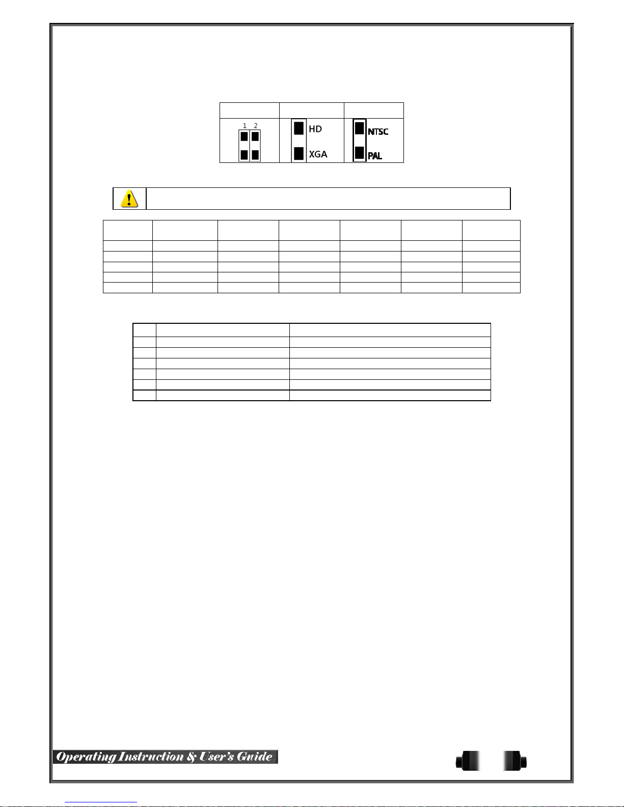
CONFIG SWITCH Setup
Switch 1 Switch 2
2-3 Connection of Other Devices
960H Series has different features as desc ribed bel ow. Be cautious.
Audio 16 8 16 4 8 16
Sensor 16 8 16 4 4 16
Relay 1 1 1 1 1 1
POS 1 1 1 1 1 1
Loop 16 8 16 - - -
Connect the PTZ controller cable, audio input/output, network, and sensors a s shown below.
1) SPOT Monitor
Connect Spot Monitor to the rear SPOT terminal.
960H series supports 1ea SPOT terminals.
2) Audio Input/Output
RUGGED HD-16CH supports 16ea audio inputs.
VERTEX VAULT-16CH supports 16ea audio inputs and VERTEX VAULT-08CH supports 8ea audio inputs.
VID SAFE-04 supports 4ea audio inputs, VID SAFE-08 supports 8ea audio inputs & VID SAFE-16 supports 16ea
audio inputs.
Item
RUGGED
HD-16
1 SPOT Monitor(CCTV Monitor) Rear Panel SPOT
2 Mike / Speaker Rear Panel Audio Input / Audio Output
3 LAN Cable Rear Panel Ethernet
4 PTZ Camera Rear Panel Terminal Block
5 Sensor / Relay / POS Rear Panel Terminal Block
6 Keyboard controller Rear Panel Terminal Block
Connecting Device DVR Terminal
VERTEX
VAULT-08
VERTEX
VAULT-16
VID SAFE-
04
VID SAFE-
08
VID SAFE-
16
16
Page 18
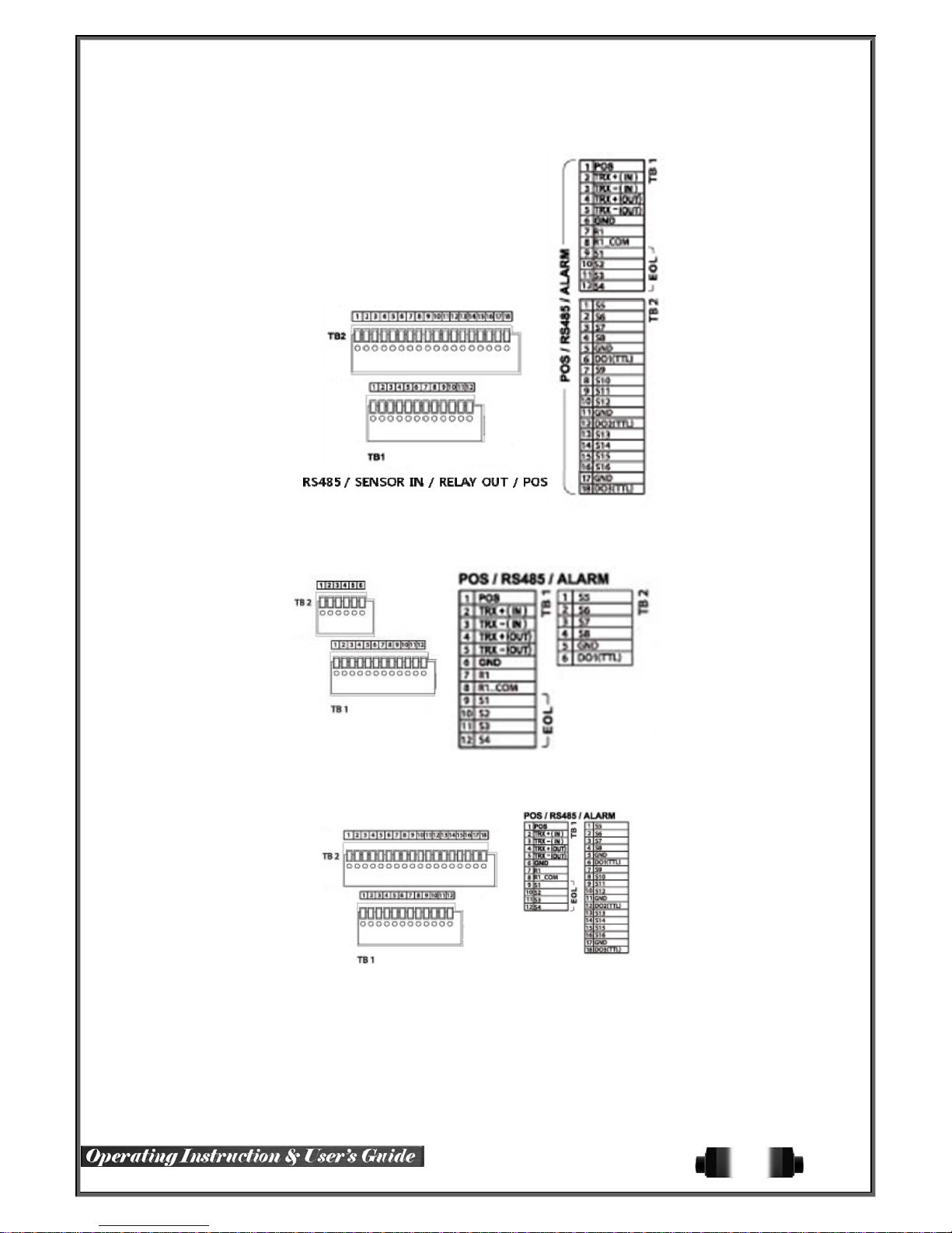
3) Terminal Block
[Figure 2-7. RUGGED HD-16CH Terminal Block and Description]
[Figure 2-8. VERTEX VAULT-08 Terminal Block and Description]
[Figure 2-9. VERTEX VAULT-16 Terminal Block and Description]
17
Page 19
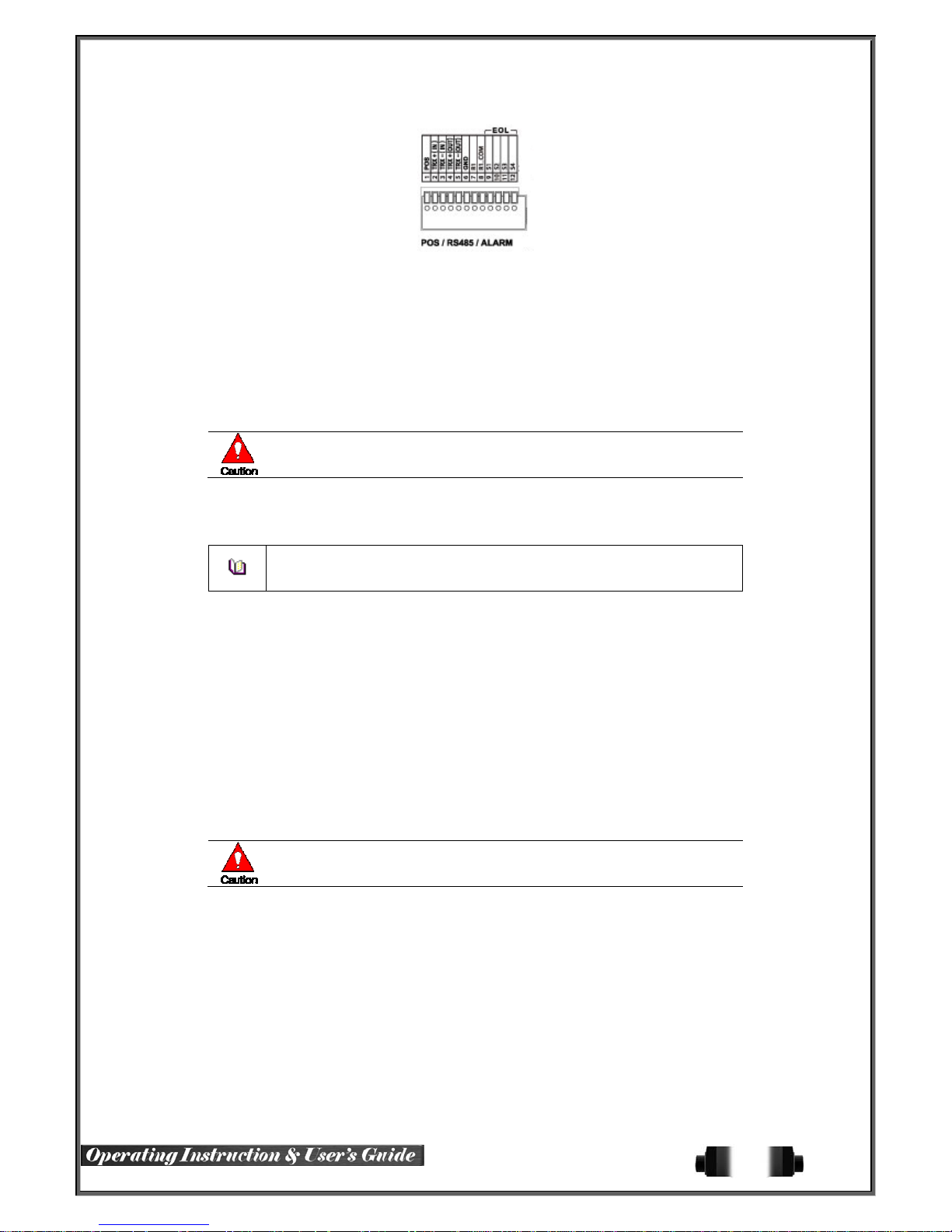
[Figure 2-10. Vid Safe Series Terminal Block and Description]
The terminal blocks in the rear of the product are for the connection of PTZ / Sensor / Relay / POS Connection.
The number of the terminal block may be different depending on the mo del.
① PTZ Camera/Keyboard Controller
Connect PTZ control cable; TRX+, TRX- and GND to Terminal Block(TB1);No.4 TRXD+, No.5 TRXD- and No.10
GND in the rear of DVR. You may refer to APPENDIX for supported PTZ camer as in this manual. Keyboard
controller has the same connection as PTZ camera.
PTZ Camera may not be working properly if GND is not connected.
② Sensor/Relay /POS
Connect Sensor/Relay/POS to the terminal block directly depending on the model .
Sensor and Relay Type
NC(Normal Close) : Normally closed; opens when a signal is received
NO(Normal Open) : Normally open; closes when a sign al is received
(1) Sensor Connection
① Connect the sensor to the terminal block S1 ~ S16 depending on the model.
② Each input terminal is connected relatively with the channel number.
(2) Relay Connection
③ Relay the output signal to external devices such as Alarm and Siren.
④ Connect the relay to R1/R2/R3/R4 terminal block depending on the model
(3) POS Connection
⑤ Connect the POS device.
⑥ Connect the POS to Terminal Block POS.
The external alarm device may require the power supply depending on its type.
Be cautious.
18
Page 20
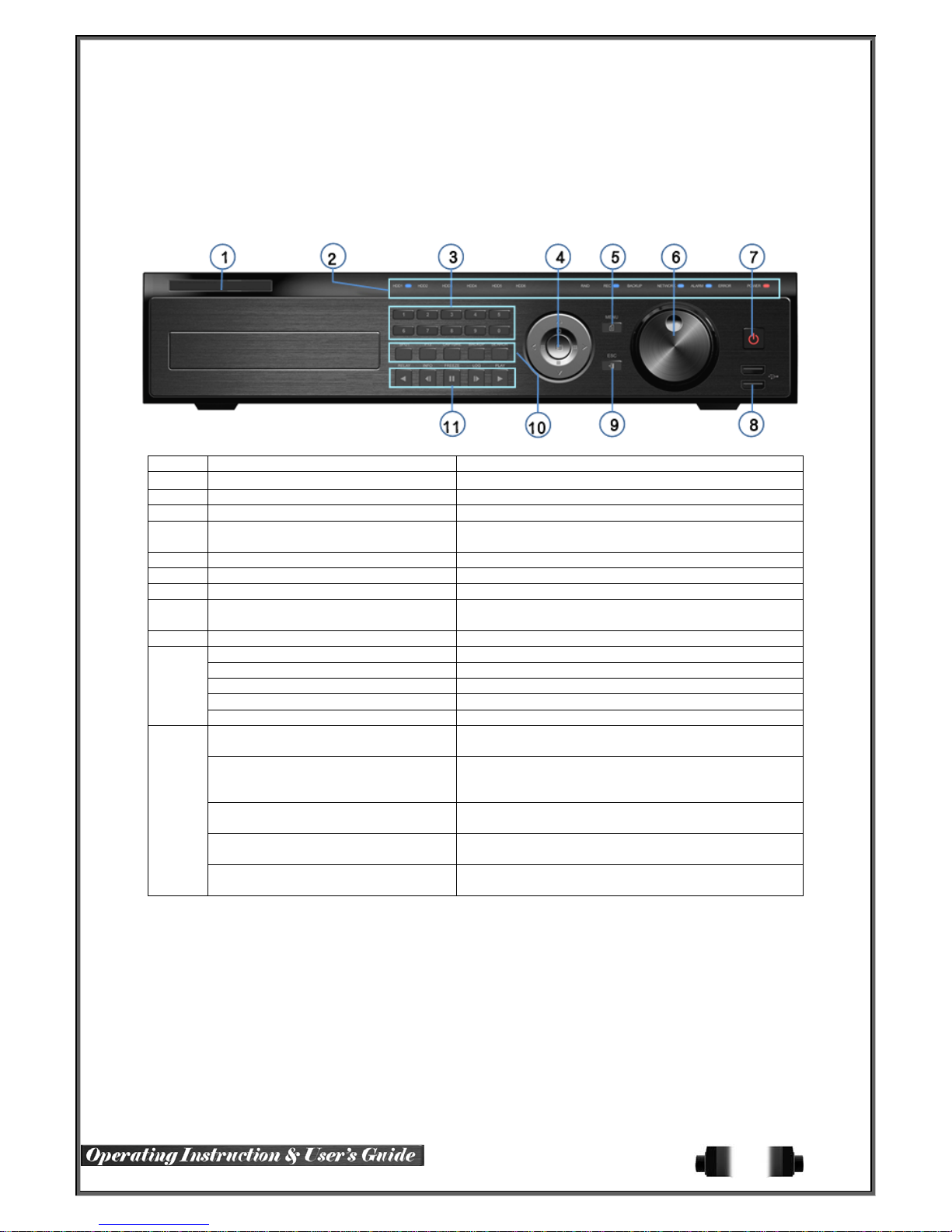
Chapter 3. Operation and Setup Tools
960H Series can be controlled easily by using the front panel buttons, front panel, remote controller, jogshuttle
and mouse.
3-1 Rugged HD Series Front Panel Button
No. Name Function
1 LABEL
2 LED DISPLAY HDD and System Power and Status Indication LED
3 Number Button Channel Selection or Number Input
4 MOVE & DISPLAY & Select
5 MENU Various Modes
6 JOG & SHUTTLE Speed in Playback Mode / Play Direction / Frame Play
7 POWER Turn the system power ON or OFF
8 USB Port
9 ESC Exit the current menu or move to the upper menu
SPOT Spot Control
PTZ PTZ Pan/Tilt/Zoom Cont rol
10
11
CAPTURE Capture the displaying image into USB
BACKUP Save the recorded image at other media.
SEARCH Search the recorded Image.
Reverse Play / Fast Reverse
RELA Y
Reverse Frame by Frame
STATUS
Pause
LOCK
Forward Frame by Frame
LOG
Forward Play / Fast Forward
PLAY
Brand Name and Model Name
Move from one category to another or change to the
display mode or select
Connection port to the USB mouse and USB memory
stick
Backward Playback/Rewind (in the Playback Mode)
Relay Control (in the Monitoring Mode)
Backward Playback Frame by Frame (in the Playback
Mode)
View System Configuration (in the Monitoring Mode).
Pause (in the Playback Mode)
Lock (in the Monitoring Mode)
Playback Frame by Frame (in the Pl ayback Mode)
System Log View(in the Monitoring Mode)
Playback/Fast Forward (in the Playback Mode)
Play back (in the Monitoring Mode)
19
Page 21
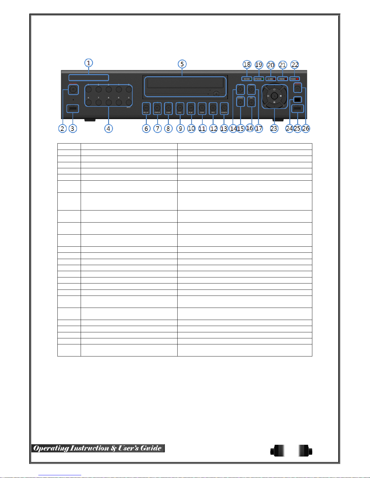
3-2 Vertex Vault Front Panel Button
No. Name Function
1 LABEL Brand Name and Model Name
2 RECORD Recording start/stop for all channels
3 USB USB Mouse or Memory USB Stick
4 Number (0~9) System Login or Number input
5 ODD CD-RW, DVD-RW
6 Reverse Play / Fast Reverse RELAY
Reverse Frame by Frame or TAB
7
STATUS
PAUSE
8
LOCK
Forward Frame by Frame or TAB
9
LOG
10
11 COPY Copy recording data
12 PTZ Change Pan/Tilt/Zoom mode
13 SEARCH Search recording data
14/15 UP/DOWN Speed control
16 ESC Exit the current menu or selects the upper menu.
17 MENU Various Modes
18 RECORD LED Green LED turned on upon HDD operation
19 NETWORK LED Green LED turned ON during remote access
20 ALARM LED
21 ERROR LED
22 POWER LED Power LED On/Off
23 SELECT Select the menu or sequence
23 MOVE & DISPLAY Select the menu or change the display mode
24 IR Sensor Remote controller input sensor
25 USB port
Forward Play / Fast Forward
PLAY
Backward Playback/Rewind (in Playback mode)
Relay Control (in Monitoring mode)
Backward Playback Frame by Frame (in Playback
mode)
View System Configuration
Pause (in Playback mode)
Lock (in Monitoring mode)
Playback Frame by Frame (in Pla yback mode)
System Log View(in Monitoring mode)
Playback/Fast Forward (in Playback mode)
Play back (in Monitoring mode)
Red LED turned on upon the occurrence of event or
motion.
Red LED turned on upon fan defect or recording
interruption.
Connection port to the USB mouse and USB memory
stick
20
Page 22
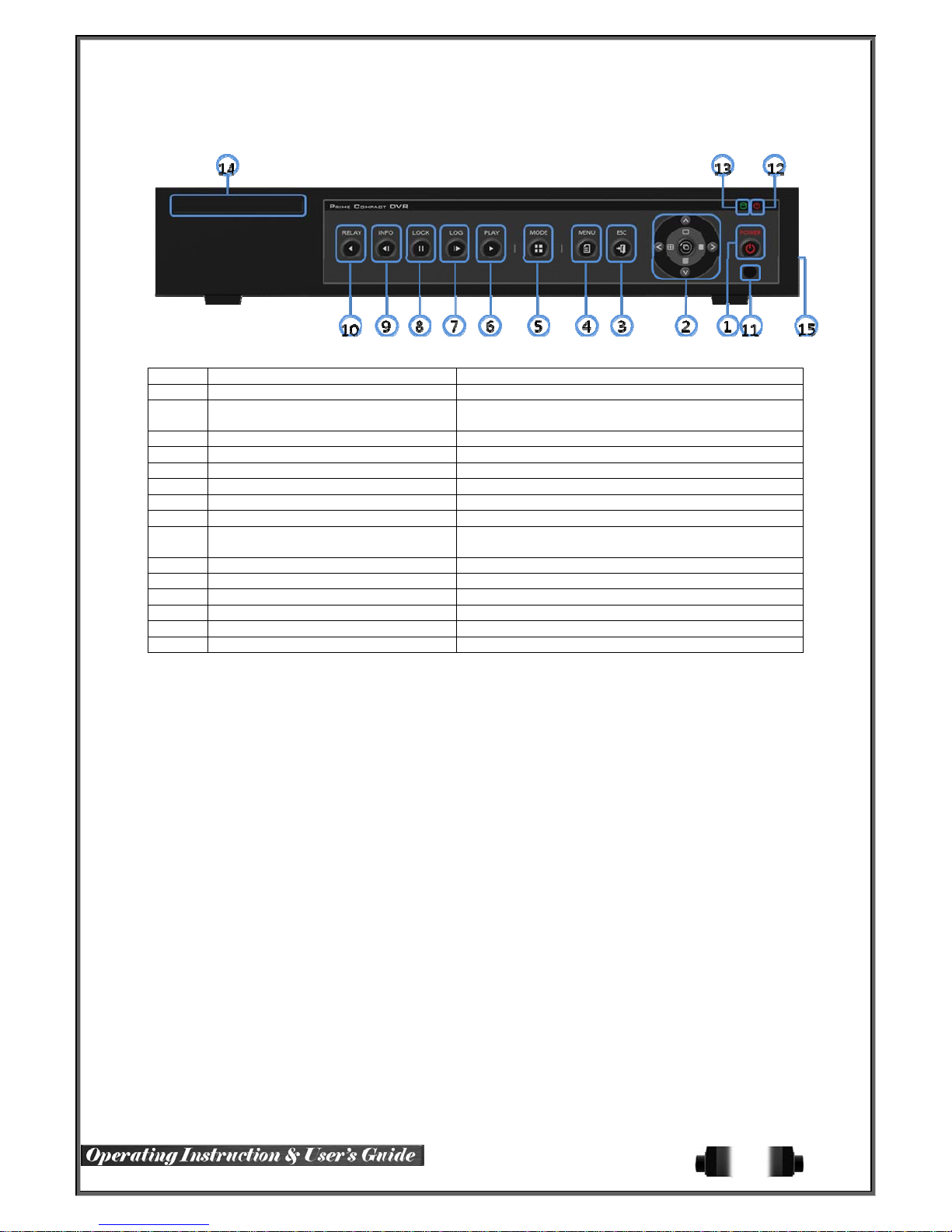
3-3 Vid Safe Front Panel Button
No. Name Feature
1 POWER Power On/Off
2 MOVE & DISPLAY
3 ESC Exit the current menu or selects the upper menu
4 MENU Various Modes
5 MODE Menu for display mode
6 PLAY Playback/Fast Forward (in Playback mode)
7 Frame by Frame Playback Frame by Frame (in Pla yback mode)
8 PAUSE Pause (in Playback mode)
9 Reverse Frame by Frame
10 Reverse Play Backward Playback/Rewind (in Playback mode)
11 IR Sensor Remote controller input sensor
12 POWER LED LED indicating Power On/Off
13 RECORD LED Green LED turned on upon HDD operation
14 LABEL Brand Name and Model Name
15 USB [Side] USB Mouse, USB Memory Stick Connection Port
Move from one category to another or change the
display mode
Backward Playback Frame by Frame (in Playback
mode)
21
Page 23
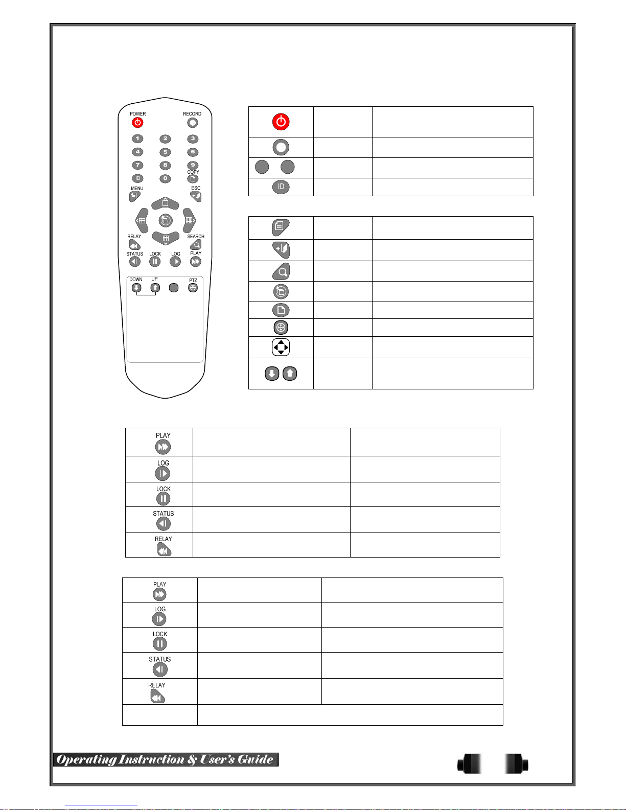
3-4 Rugged HD-16 Series Remote Controller
A) Basic Control Button
1
~0
B) System Operation and Setup Button
C) Search Button (Playback Mode)
Play /
Fast Forward
Frame by Frame Play forward frame by frame
Pause Pause
Reverse Frame by Frame Reverse play frame by frame
Reverse Play /
Fast Reverse
D) Buttons for Other Features (Monitoring Mode)
POWER
RECORD
Turn the system power
ON or OFF.
Record all channels or stops recording
all channels.
NUMBER Input of numeric data.
ID Set up the remote controller ID.
MENU Data, Schedule, System Set up
ESC
Exit the current menu
or Move to the upper menu.
SEARCH Search recorded images.
SELECT
Select the category or execute
automatic screen conversion.
COPY Copy recorded videos.
PTZ Shift to the PT Z cam e ra co ntro l mo de .
MOVE
UP/
DOWN
Move from one category to another or
change to the display mode.
Log Page Up/Down
Play/Fast-forward
Reverse play/ Rewind
PLAY Play the recorded images.
LOG
LOCK Lock the system
STATUS
RELA Y View the relay status and manual operation.
View t he system
log list.
View system information and changes the
display setup.
※ Setting up the remote controller ID
22
Page 24

Example) When the remote controller ID is set to 1
Press the {ID} button, enter {0} and {1}, and press the {ID} button aga in .
To control all DVRs with the different ID, set the remote controller ID to 999.
3-5 Vid Safe / Vertex Vault Series Remote Controller
POWER
MODE
FULL 1CH Mode
QUAD 4CH Mode
9 SPLIT 9CH Mode
16 SPLIT 16CH Mode
SEQ. Sequence Mode ON/OFF
B) System Operation and Setup Button
MENU Data, Schedule, System Set up
ESC
PREV Move back (Reverse)
Turn the system power
ON or OFF.
Exit the current menu
or Move to the upper menu.
PAUSE Pause
FORWARD Move fo rward
BACKWARD
PLAY Play
Playback
3-6 Mouse
The mouse pointer as shown below appears if a mouse is connected to the USB terminal at the front panel.
Mouse Control functions are shown below.
Click on the right
button
Click on the left
button
Double click on the
left button
Click the left button
and drag
Monitoring Mode / Move from Play Mode to Monitoring
Menu / Pop up or remove Play Menu.
Show sub-folder of the certain Menu window.
Select Menu.
Select Menu.
Move a certain window.
23
Page 25
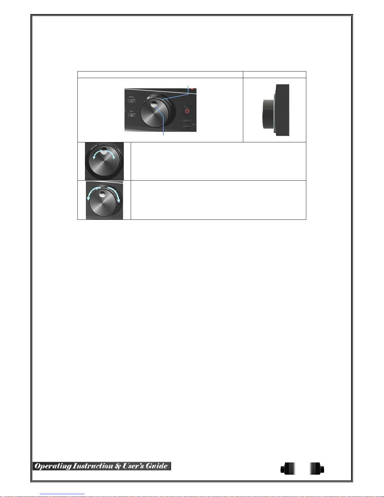
3-7 Jog/Shuttle
In the playback mode, control the play direction, speed and frame.
Front Side
Speed and Direction Control
Frame Control
※ Play Direction Control
This is available in the playback mode. Turning the jog right/left plays
forward/reverse frame by frame.
※ Speed and Direction Control
This is available in the playback mode. Turning the jog right/left plays
forward/reverse x1/x2/x4x30.
24
Page 26
Chapter 4. DVR Operation Setup
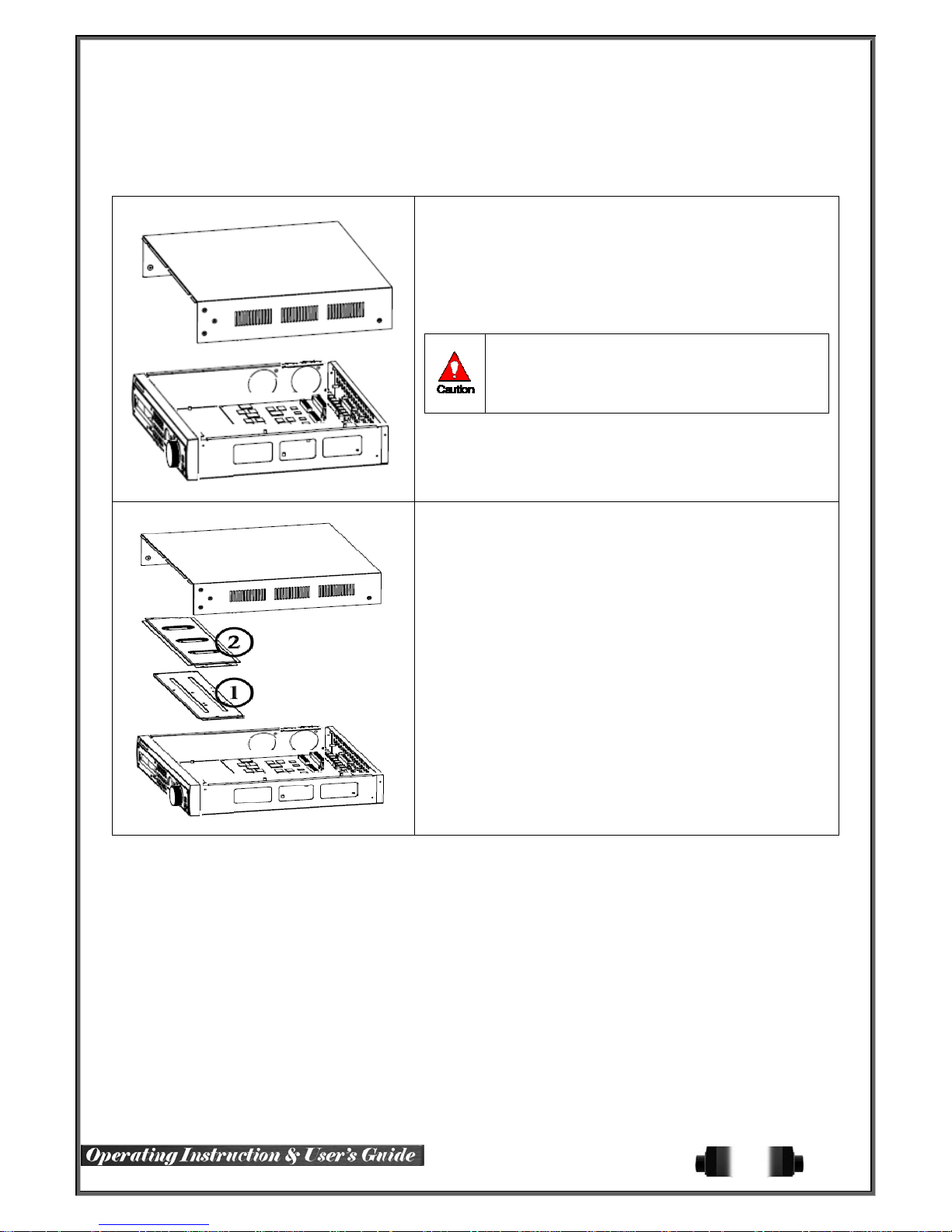
4-1 Rugged HD Series Storage Installation
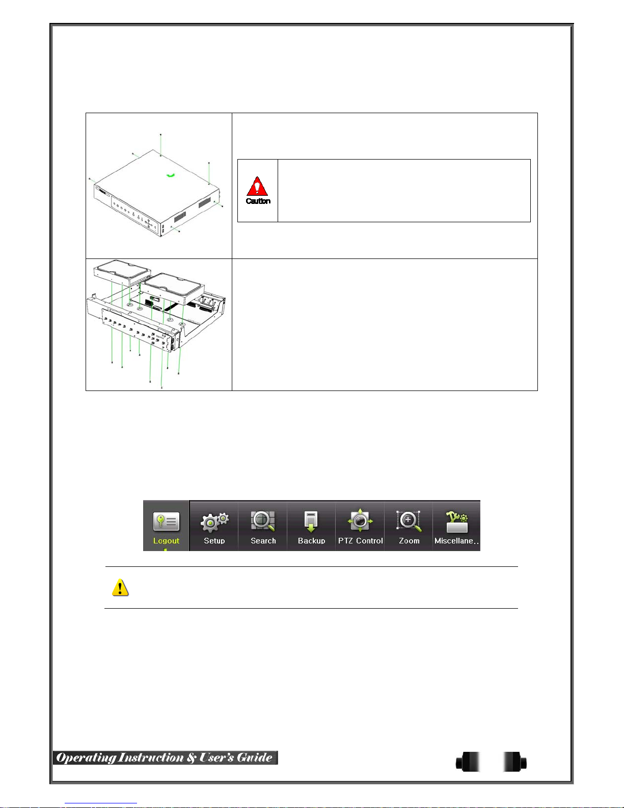
※ Step 1
1) Using a screw driver, unscrew and take off the top case of the
product.
1) Normal termination of the system and fully unplugged power
code are required before conducting HDD installation.
2) After installing HDD, Do not connect to power supply with
the top case opened. The top case must be covered before
usage.
※ Step 2
2) Using a screw driver, unscrew the fixing bolt of the top HDD bay
② and separate the top HDD bay② from the body.
3) Using a screw driver, unscrew the fixing bolt of the bottom HDD
bay① and separate the bottom HDD bay① from the body.
25
Page 27
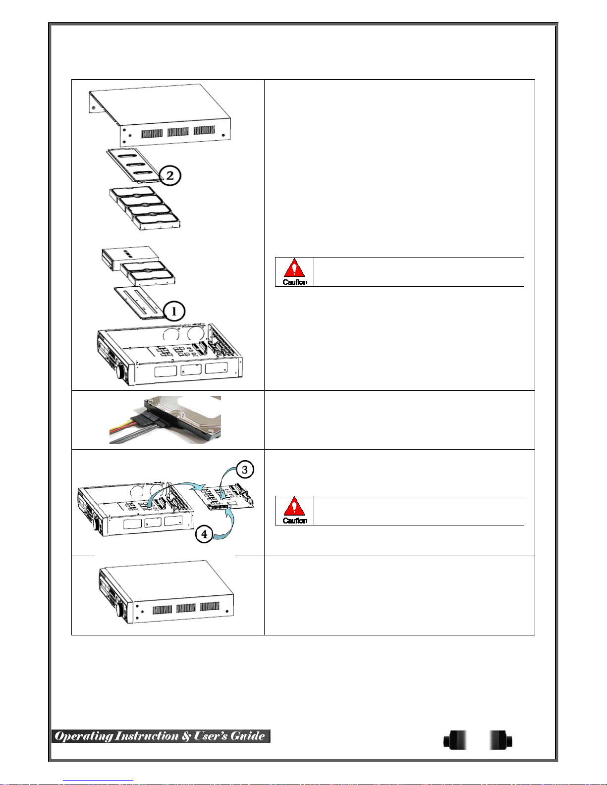
※ Step 3
4) Align screw holes and screw and fix HDD onto the bottom HDD
bay①.
5) Align screw holes and screw and fix HDD onto the top HDD bay②
6) By reversing Step 2, combine both top② and bottom① HDD bay
with the body.
1) H-model can hold HDD up to 6ea
2) HDD power and data terminal should face the
inner direction.
※ Step 4
7) Connect the power cable and data cable to HDD.
※ Step 5
8) Power terminals(
terminal(
9) Connect the HDD data cable into the mainboard data cable
connector(④).
※ Step 6
10) Reassemble the top case by reversing 1) to finalizing HDD
installation.
③). Connect the power cable into the power
③).
※ H-model model has a different type of SATA
power cable.
26
Page 28
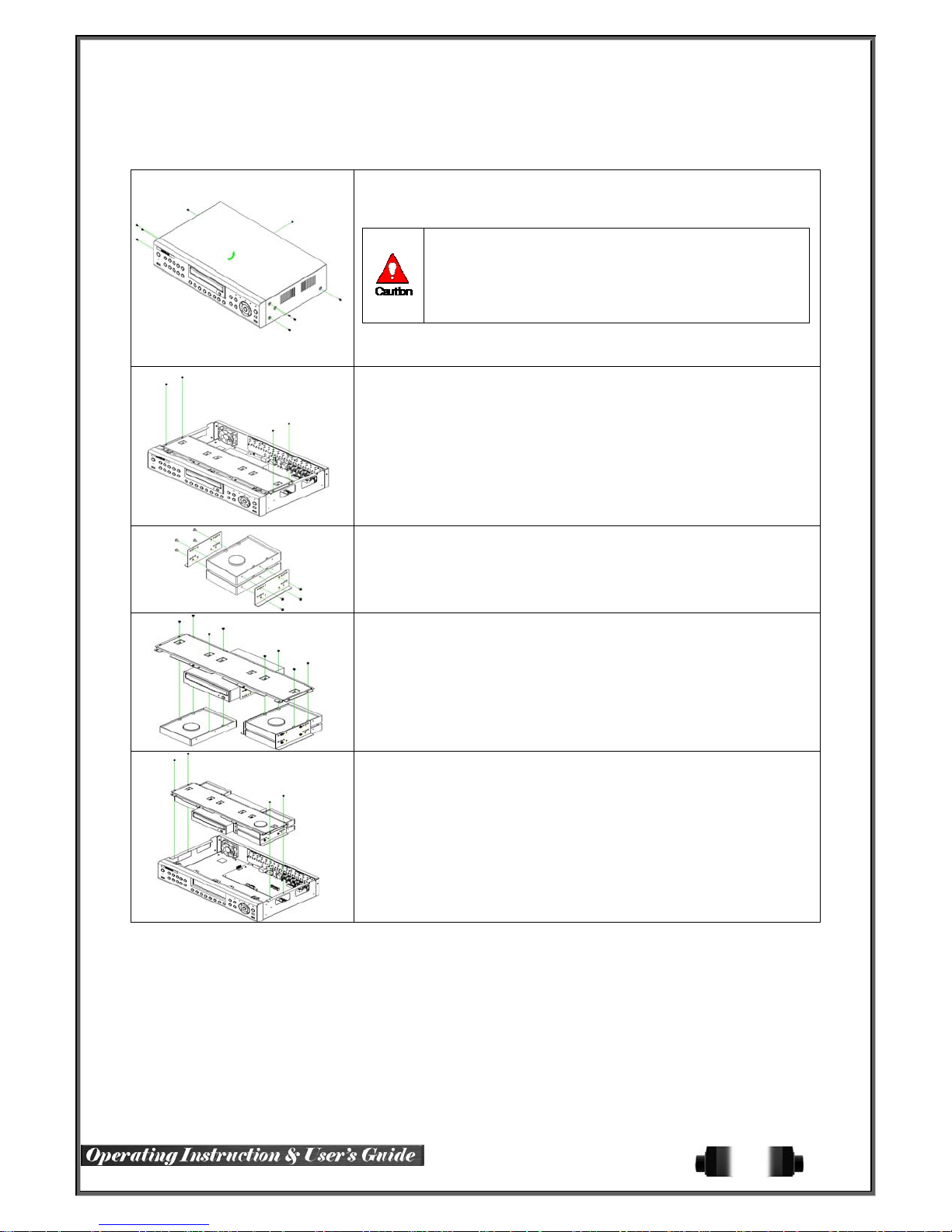
4-2 Vertex Vault Storage Installation
1) Open the top case by using screw driver.
1) Normal termination of the system and fully unplugged power code
are required before conducting HDD installation.
2) Touch a grounded metal substance or ground yourself before
installing HDD in order to reduce static electricity. Static electricity may
cause a malfunction of the product.
3) After installing HDD, Do not connect to power supply with the top
case opened. The top case must be covered before usage.
2) Unscrew and separate the HDD bay from body.
3) Screw the HDDs to the HDD bay.
4) As per the photo, Screw the HDD bay, HDD and DVD to the top bay.
5) Connect the power cable and data cable on HDDs and then reassemble
the top case by reversing 1) t o finalizing HDD install ation.
27
Page 29
4-3 Vid Safe Storage Installation
1) Open the top case by using screw driver.
1) Normal termination of the system and fully unplugged power code
are required before conducting HDD installation.
2) Touch a grounded metal substance or ground yourself before
installing HDD in order to reduce static electricity. Static electricity may
cause a malfunction of the product.
3) After installing HDD, Do not connect to power supply with the top
case opened. The top case must be covered before usage.
2) Unscrew and separate the HDD bay from body.
3) Screw the additional HDD bay to current HDD bay
4) Connect HDD to HDD connector on the main board directly without cable.
Reassemble the top case by reversing 1) to finalizing HDD instal lation.
4-4 Power ON.
① Check the Power, RUGGED HD-16 Model (90 ~ 250V, 50/60Hz) and connect the power.
② Once Power cable is connected (fou nd in Rear Side), bo otin g w ill be enable d. .
③ After booting is finished, the live screen and channel indication / clock are shown.
④ Menu window pops up by clicking the right button of the mouse or pressing [MENU] button in the
front panel as shown below.
ID and Password are required for initial installation. Default ID and Password are shown below.
[ admin : 00000 ] [ User1 : 1111111 ] [ User2 : 2222222 ]
[ User3 : 3333333 ] [ User4 : 4444444 ].... [ User10 : aaaaaaa ] [ User11 : bbbbbbb ]....
※ Password is available to change at {Menu} {Setup} {System} {Modify}.
[Figure 4-11. Menu Window]
28
Page 30
4-5 Storage Setup
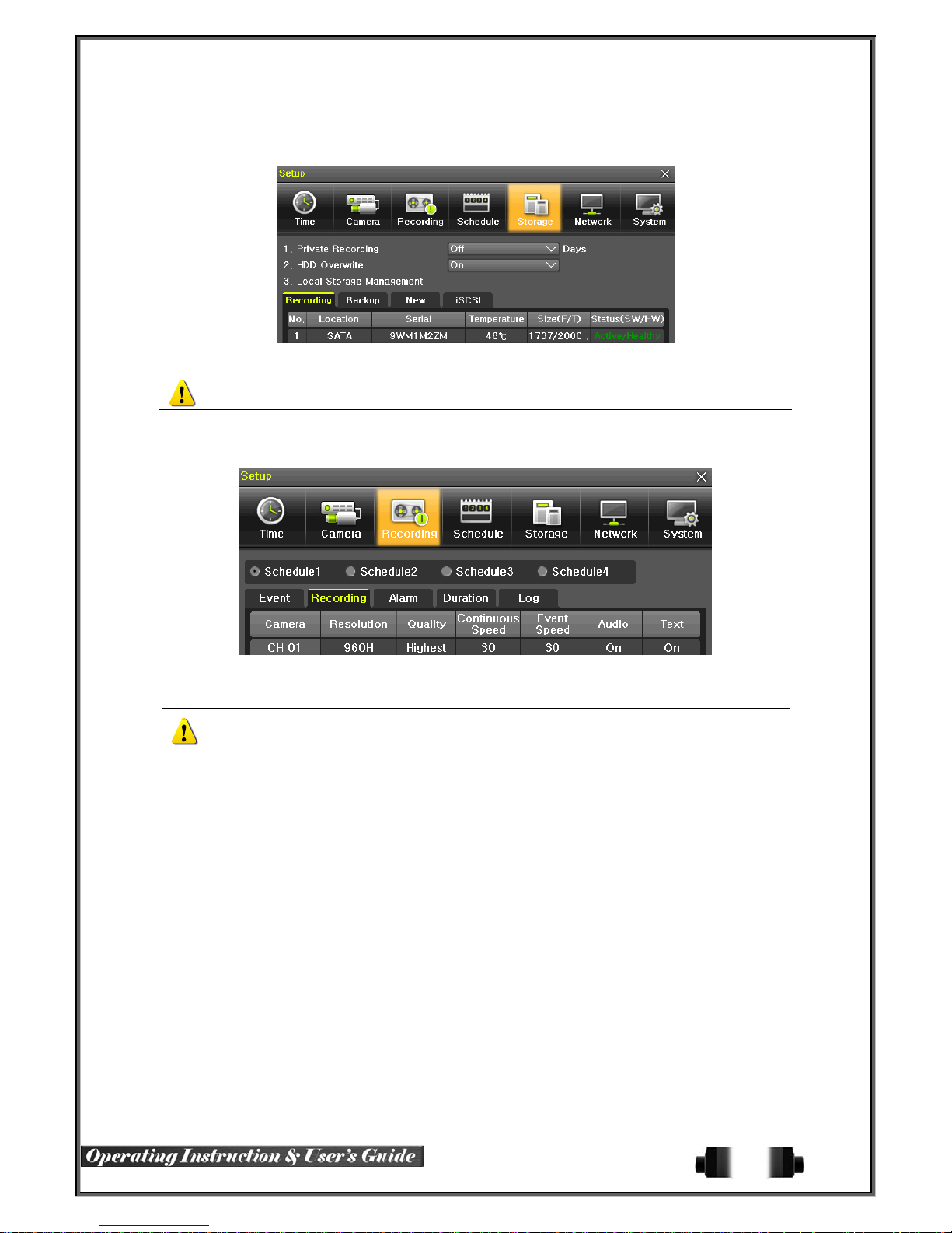
① Select {Menu} {Setup} {Storage} and configure HDD.
For more detail about HDD and external devices, check [6-5 Storage].
4-6 Recording Setup
① Select {Menu} {Setup} {Recording} {Recording}
② Setup [Recording Resolution]/[Recording Quality]/[Continuous Speed]/ [Event Speed]/[Audio]/[Text].
The initial recording setup is [Recording Resolution: 960H] [Recording Quality: High]
[Continuous Speed: Off]. An image of the connected cameras is recorded with above setting.
For more detail, check [6-3 Recording Setup].
4-7 Date/Time Setup
① Select {Menu} {Setup} {Time}.
② Configure [Time Sever]/[Date and Time]/[Standard Time Zone].
29
Page 31

4-8 Camera / TV Setup
① Select {Menu} {Setup} {Camera} {Adjust}.
② Set up for [Brightness/Contrast/Color/Hue/Camera Adjustment/TV OUT Adjustment] are available.
4-9 Display Setting and Other Setup
① Select and set up {Menu} {Miscellaneous} {Display Setting}.
4-10 External Device Setup
① Configure external devices. For more information, check [2-3 Connection of other devices], [Chapter
5. System Operation], [6-2 Definition], [6-6 Network], [6-7 System].
4-11 Search
① For more information, check [5-6 Search], [5-7 Calendar Search], [5-8 Playback], [5-10 Recording].
4-12 Backup
① Backup is available in Monitoring, Search, Log and Playback Mode.
② For more information, check [5-11 Backup].
4-13 DVR Info.
① Move to {Menu} {Miscellaneous} {DVR Info}.
Detail information for product functions are described below in this manual.
30
Page 32
Chapter 5. System Operation
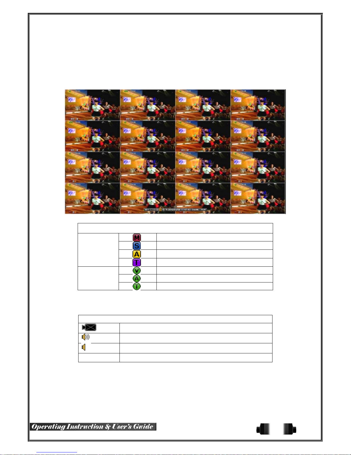
5-1 Real Time Monitoring Mode and Icon
After booting is finished, Audio/Recording Status/Channel Title/Connection Status/Time/HDD Status are displayed
as shown below.
[Figure 5-12. Recording Status Window]
※ Recording Event / Recording Mode Icon ※
Recording
Event
Recording
Mode
※ Recording Event Icons are still displayed despite of the recording stop. Recording Mode Icon
distinguish recording status.
Motion Detection Recording
Sensor Recording
Audio Recording
Text Recording
Video Recording
Audio Recording
Text Recording
※ Live Screen Icon ※
No Signal Camera has been disconnected.
Video is not conne cted
Audio is activated.
Audio is mute
31
Page 33

※ Control Bar ※
Full Screen
①
4 Channel Screen
②
8 Channel Screen
③
16 Channel Screen
④
ZOOM function
⑤
Auto Sequence Mode
⑥
Date / Time
⑦
HDD Status
⑧
Playback
⑨
5-2 System Login
5-2-1 User Account and Authorization
System users are divided into local administrators and general users and the local administrator can use all
functions.
Local Admin
User
Network Live View the real-tim e ima ge by netw ork acc e ss.
Playback View the recorded image.
Copy (Download) Copy and download the image from the network.
PTZ Control PTZ camera control
Setup
Network Upgrade Remote network upgrade
View Covert Channels Enable viewing covert channels.
5-2-2 Login
For security purpose, user must log in first to use {Monitoring Menu}.
The local administrator can use all functions: System Power On/Off, Setup,
Monitoring, and Playback .(remote access is not available, however)
Up to 15 users are allowed. Each user can access the functions depending on the
given authorities.
For Authorization Setup, Move to {Menu} {Setup} {System} {4. User
Registration}.
※ Functions available for Authorization Setup
Recording, Recording Schedule, Sys tem, Storage, Time, PTZ, Network Setup,
Screen Setup
① On the real-time monitoring window, select {Menu} {Login}.
② Enter the password or select cancel.
[Figure 5-13. Login Window]
32
Page 34
5-2-3 Logout
After logging out, the user cannot use {Menu}.
① On the real-time monitoring screen, select {Menu} {Logout}.
5-3 Monitoring
960H Model Series features powerful monitoring functions as s hown below.
1 / 4 / 9 / 16 Division Mo de and Auto Sequence Mode
Channel Grouping
960H Model (4) Spot 960H Model 1/4/9/16 Multi spot
TV mode
Menu Controlling in Monitoring Mode
Zoom
Live Event Indicat ion
Text Detection by using POS Only 1ch
Screen Control by using PTZ.
5-3-1 Screen Division and Auto Sequence
After the system is booted, images will be displayed on a screen divided into [16/9] division depending on the
model. Except for the basic setting, the system follows user’s setting on the screen division from next booting.
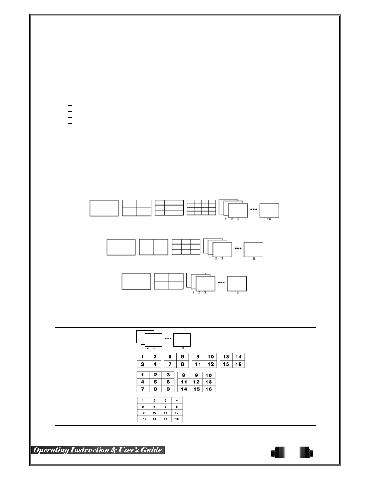
H-model series provides the 7 screen division mode including 1 / 4 / 9 / 16 / Auto Sequence and 1/4/9/16 are
Basic Mode.
[Figure 5-14. 960H Model 16CH Channel Mode]
[Figure 5-15. 960H Model 8CH Channel Mode]
[Figure 5-16. 960H Model 4CH Channel Mode]
※ In Basic Mode;1/4/9/16, pressing the same mode button leads to screens as shown below.
1 Channel Division Mode
(16 Group )
4 Channel Division Mode
( 4 Group )
9 Channel Division Mode
(2 Group)
16 Channel Division Mode
(1 Group)
33
Page 35

※ The user can view an image on full screen by double-clicking a desired channel in the 4/9/16 SubScreen mode. Double-click any part of the screen to return to the previous mode.
※ Auto Sequence
Auto Sequence is to rotate images at an interval of the certain time in 1/4/9 Basic Div ision. Auto Sequence
is not available in the Basic 16 Division mode.
① Move to {Menu} {Miscellaneous} {Display Setup }.
② Pressing Front {SELECT} Button / Remote Controller {SELECT} Button / Mouse Arrow Button initiate the
Auto Sequence mode.
.
③ Auto Sequence in Basic 1 / 4 / 9 Division Mode
1 Channel Mode Sequence 4 Channel Mode Sequence 9 Channel Mode Sequence
5-3-2 Channel Grouping
Channel Grouping is to switch the image location in the screen between channels in the monitoring mode.
① On the real-time monitoring screen, select {Menu} {Miscellaneous} {Channel Grouping}.
② Select a channel to be switched after moving a yellow-focused selection window.
③ Select a channel to be switched when the window shows.
④ The Image location of the each channel is changed.
5-3-3Spot
Spot is to output a channel that is set with a certain function and Spot has an independent monitor and output.
34
Page 36
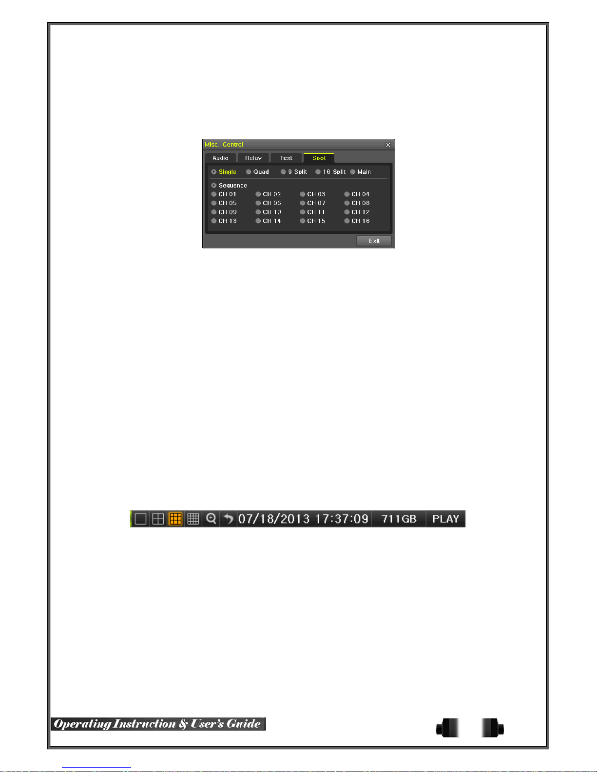
The priority for Spot is Manual Spot > Event Spot > Sequence Spot.
① Manual Spot
The user can designate a spot channel manually.
RUGGED HD-16 Model 16CH supports 4ea Spot channels.
[Figure 5-17. Spot]
② Move to {Menu} {Miscellaneous} {Misc. Control} {Spot} and configure on the Single
mode, Quad mode, Sequence and Channel.
③ Event Spot
Event Spot is to show a channel quickly that is set with the event function in case events (Sensor, Motion and
Audio) occur. The event check interval is one second. If events are detected in many channels, it shows a
channel with the last event. Move to {Menu} {Setup} {Recording} {Alarm} {Spot}.
④ Sequence Spot
The user can select more than one channel in Manual Spot and have a sequential image through Spot. Move to
{Menu} {Miscellaneous} {Control} {Spot} {Sequence}.
⑤ TV
The TV Monitor can be used to view the same display as the ‘Spot’ screen. Move to {Menu}
{Miscellaneous} {Control} {Spot} {Main}.
5-3-4 Menu in Monitoring Mode
The user can control all functions available in Monitoring Mode in {Menu}.
① Press the Menu or right-click mouse button. The {Menu} will then appear.
② Select the desired item by using the arrow keys or mouse.
③ Press the ESC button or right-click mouse button to end the menu.
5-3-5 Zoom
Zoom is to zoom in or out the 1 channel division image in the real time monitoring mode.
④ Move to {Menu} {Zoom} or press the zoom icon from the control bar in the real time
monitoring mode.
⑤ After selecting a channel, it becomes the 1 channel mode and the zoom control screen shows at
bottom-right.
35
Page 37
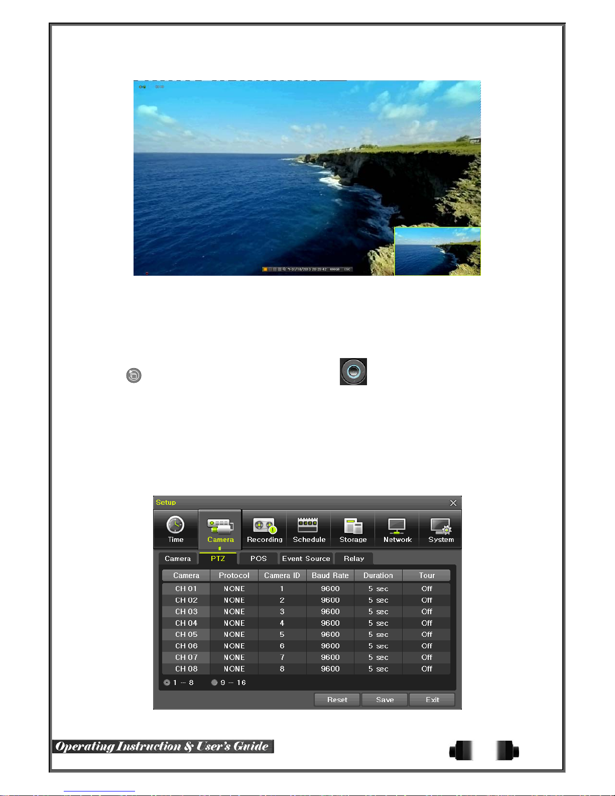
[Figure 5-18. Zoom Control Screen]
⑥ In case of the mouse, move the pointer to an area to be zoomed in the zoom control screen and
double-click on it.
⑦ Then, it zooms in 3 levels; Normal, x4, x16. Those 3 levels can be controlled by the wheel of the
mouse. The user also can left-click and drag the yellow box to move the focused image in higher
than the x4 mode.
⑧ In case of the remote controller and front panel, it is available to move to 3 levels by using
{SELECT} button in the remote controller and {SELECT} button of the front button.
The yellow box can be moved by the arrow keys.
5-3-6 Screen Control by using PTZ
This enables the user the real-time monitoring by using PTZ camera.
The PTZ camera must be connected to the system. For external connection, refer to [2-3 Connection
of Other Devices
① Configure Protocol / ID / Baud Rate / Duration / Tour.
] [3) Terminal block]. Select {Menu} {Setup} {Camera} {PTZ}.
[Figure 5-19. PTZ Setup]
36
Page 38
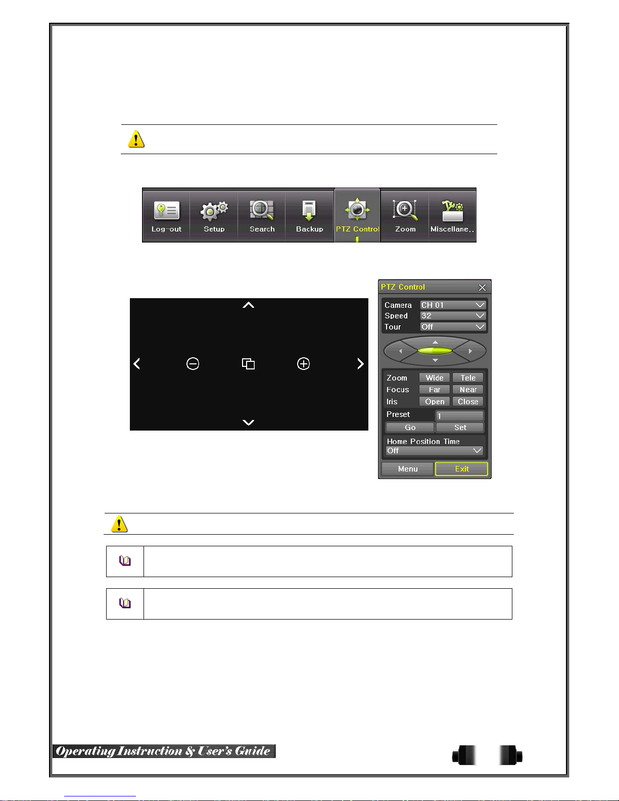
※ Baud rate can be selected at 2400/4800/9600/19200/ 38400.
※ Duration can be selected at 5/10/15/20/5-60(User setting) seconds.
※ Tou r consists of Tour 1/ Tour 2 and each tour can be set with 8 Preset.
※ RUGGED HD-16 Model series supports 28 protocols for PTZ control. For
② To control PTZ camera, select {PTZ Control} in Menu or press {PTZ} in the remote controller.
supported protocols, refer to APPENDIX.
[Figure 5-20. PTZ Control]
[Figure 5-21. PTZ Control Mini/Full]
In the PTZ mode, there are two function; Full and Mini. Tour has [Tour1] and [Tour2]. Home
Position Tim e is 1/ 5/10 / Use r set tin g (1-6 0 )minu te s .
Preset? Using horizontal/vertical/ Zoom/Focus/Iris movement of PTZ Camer a, zoom or focus
or Iris a certain spot of the image by designating the coordinates and move to the designated
coordinates quickly.
Home Position Time? If there are no controlling sign als to PTZ camera after a certain ti me, it
goes automatically to the Preset No.1 position as Preset No. 1 is designated as Home Position
37
Page 39
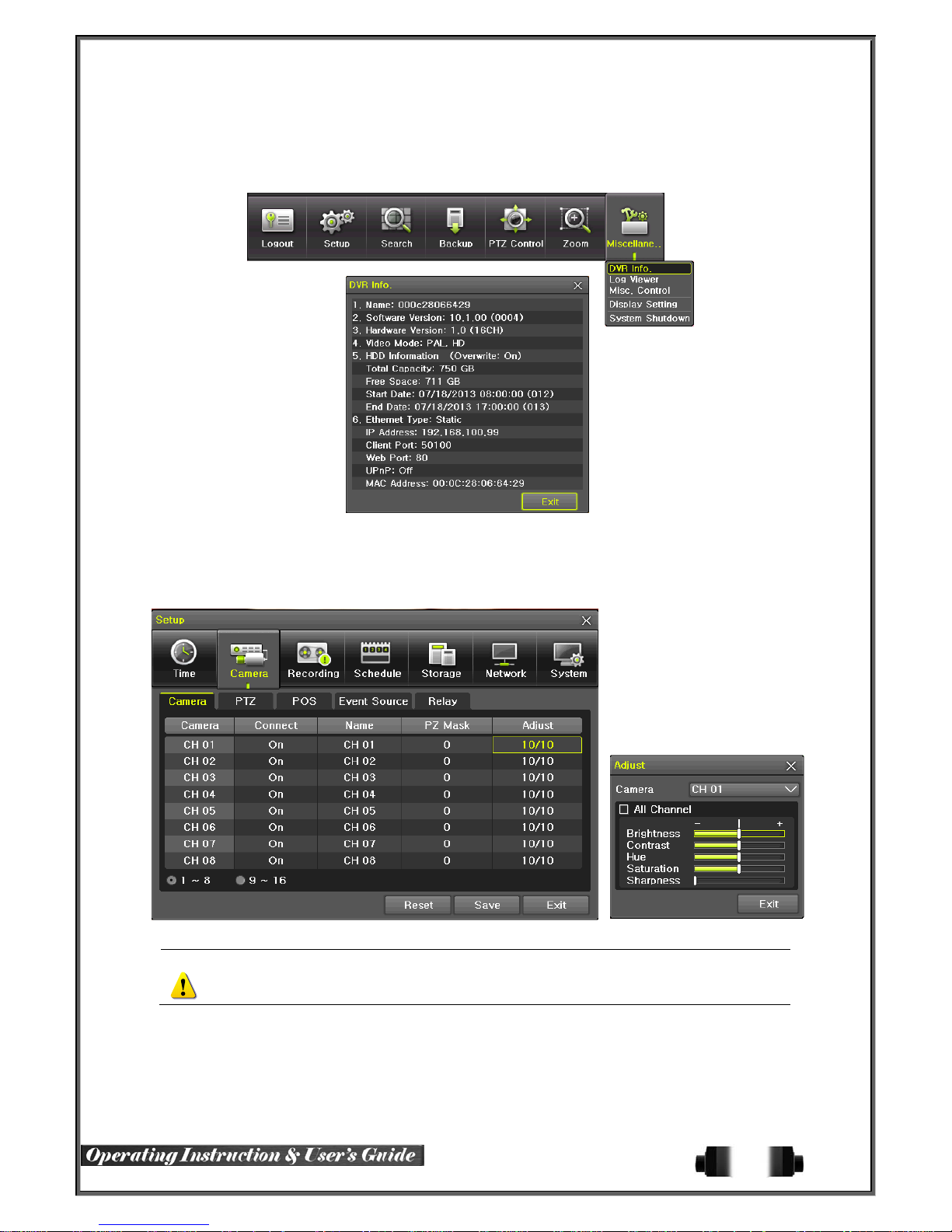
5-4 System Information and Screen Setup Change
5-4-1 System Information
[Figure 5-22. Product Information Window]
5-4-2 Screen Brightness/Contrast/Color/Saturation/Sharpen/Camera Adjustment
Select {Adjust}, then it becomes the 1 channel mode and a window pops up as show n below.
[Figure 5-23. Screen Setup Window]
Moving the camera, down, right, or left excessively may cause black or gray areas to appear on
the screen. The level at which such condition does not occur is the proper control range for the
camera.
38
Page 40
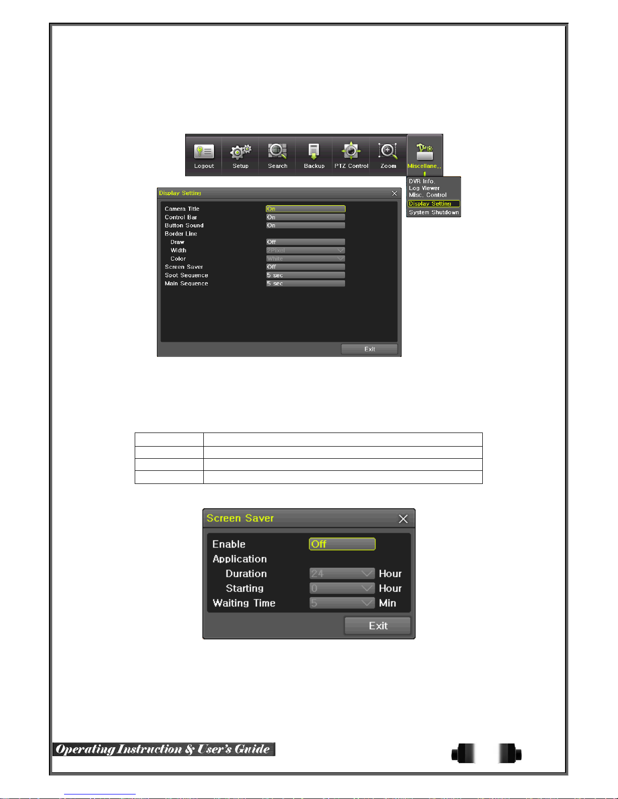
5-4-3 Display Setting
Camera Title On/Off, Control Bar On/Off, Button Sound On/Off, Border Line Draw/Width/Color, Sequence
Duration 1-10seconds. After selecting Display Setting, it becomes the 1 channel mode and a menu pops up as
shown below.
[Figure 5-24. Display Setting Window]
5-4-4 Screen Saver
Monitor connected with DVR can be shut down to protect monitor. {Menu} {Miscellane..} {Display
Setting} {Screen Saver}
Name Function
Duration Screen Save duration setting
Starting Screen Save starting setting, 0 to 24
Waiting Time Screen Save activating term when there is no input
[Figure 5-25. Display Setting Window]
39
Page 41
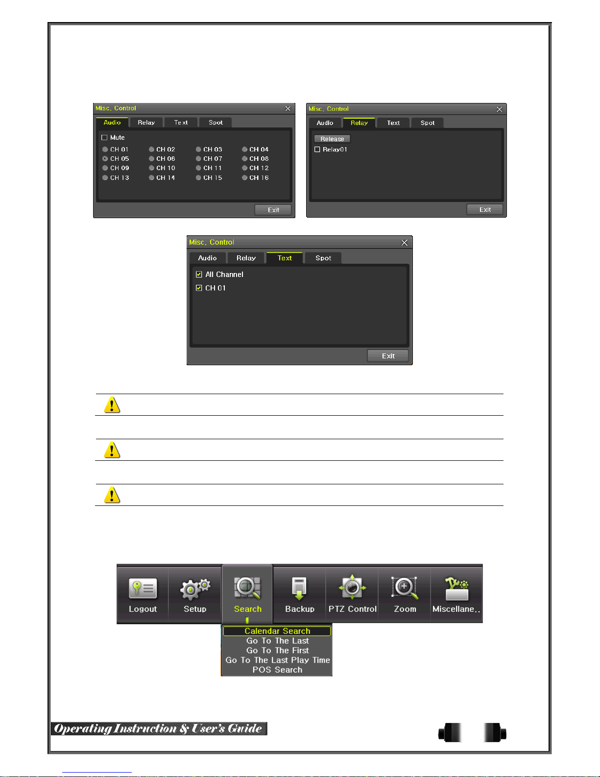
5-5 Control
In the real-time monitoring, move to {Menu} {Miscellaneous} {Misc. Control}.
[Figure 5-26. Audio] [Figure 5-27 . Relay]
[Figure 5-28. Text]
① Move to the Audio tab and select the channel to be activated or Mute.
960H-model 16CH support 16 channel audios, 960H-model 8CH model support 8 channel audios
and 960H-model 4CH model support 4 channel audios.
② Move to the Relay tab and select.
All H-model support 4 ch annel input.
③ Move to the TEXT tab and select.
H-model 16CH model support 1-16 channel text input and H-model 8CH model support 4 channel
text input.
5-6 Search
5-6-1 Search Mode
Move to {Menu} {Search} in the real-time monitoring mode.
[Figure 5-29. Playback Menu]
40
Page 42

5-6-2 Playback Menu
(1) Calendar Search
Calendar Search allows the user search and playback by [Year/Month/Day/Hour/Minute],[Multi-Channel/MultiTime/Multi-Day]and [Motion/Sensor/Audio/Pattern].
(2) Go To The Last
The user can search and playb ack the last recorded data by Multi-Channel Mode.
(3) Go To The First
The user can search and playback the first recorded data by Multi-Channel Mode.
(4) Go to The Last Played Time
The user can playback from the last played time by Multi-Channel Mode.
(5) POS Search
Text Data can be searched and used for playback [Year/Month/Day/Hour/Minute],[ Text 1~3]
※ Go To The First and Go To The Last are only available in {Multi-Channel}.
5-7 Calendar Search
5-7-1 Search Mode
On the real-time monitoring screen, select {Menu} {Search} {Calendar Search} and then a searching
window pops up as shown below.
5-7-2 Year/Month/Day Selection
Select the desired [Year/Month/Day]. The color of the icon at the top-left of square in the calendar indicates the
recording status.
5-7-3 Time Index
① Every time when the user changes the time at {Menu} {Setup} {Time} {Date and Time}
tab, a new folder(Index) is created and files saved in the folder before the time change can be fo
und at {Menu} {Calendar Search} {Time Index}.
② Selecting a file at {Menu} {Calendar Search} {Time Index} leads to a selection window pop
up and the user can select a file in different folders (before time change).
Start Time The Recorded Start Time
End Time T h e Rec o rde d End Time
[Figure 5-30. Search Window]
41
Page 43
5-7-4 Event
Event is to search the data by the events. Select [All/Motion/Sensor /Au di o/Pat tern/Text].
5-7-5 Multi-Channel Search
The Multi-Channel Search is to play recorded images of the different channel over a certain designated time.
① Select the desired Year/Month in the calendar window.
② After selecting the desired search date, each channel is then displayed in the hour bar graph.
The bar graph color in the real-time monitoring mode is same with record ing event functionally.
③ Move the time line to a specific time point by using the arrow keys or the numeric buttons and pr
ess the Search button.
④ Selecting the time leads to the recorded video display of each channel in the minute bar graph.
⑤ Move the time line to a certain time point by using the arrow keys and the numeric buttons and p
ress the Select button. Playback will then start from the specified time point.
5-7-6 Multi-Time Search
The user can playback the video contents of the certain channel recorded in the different time zone
simultaneously.
Entering into the search mode during the Multi-Time playback leads to the Multi-Time Search.
① The way of the date search is same as the Multi-Channel Search.
② The hourly recording status of the selected date is viewed after selecting a desired date.
③ Select the start time and channel by using the arrow keys.
④ The hourly displayed video of the selected channel will then be displayed in the minute bar graph.
⑤ Move the time line by using the arrow keys and the numeric buttons and specify the time. Afterwa
rd, press the Start button and play back the contents.
※ A different time zone means continuous 16 hours.
5-7-7 Multi-Day Search
The user can playback the video contents of the certain channel recorded in different dates simultaneously.
Entering into the search mode during the Multi-Day playback leads to the Multi-Time Search.
① The way of the date search is same as the Multi-Channel Search.
② The date list and the hourly recording status starting from the selected date are viewed by selectin
g the desired date.
③ Select the start time and channel by using the arrow keys.
④ The recorded video of the selected channel will then be displayed as the minute bar graph.
⑤ Move the time line by using the arrow keys and the numeric buttons and specify the time. Afterwa
rd, press the Start button and play back the contents.
42
Page 44
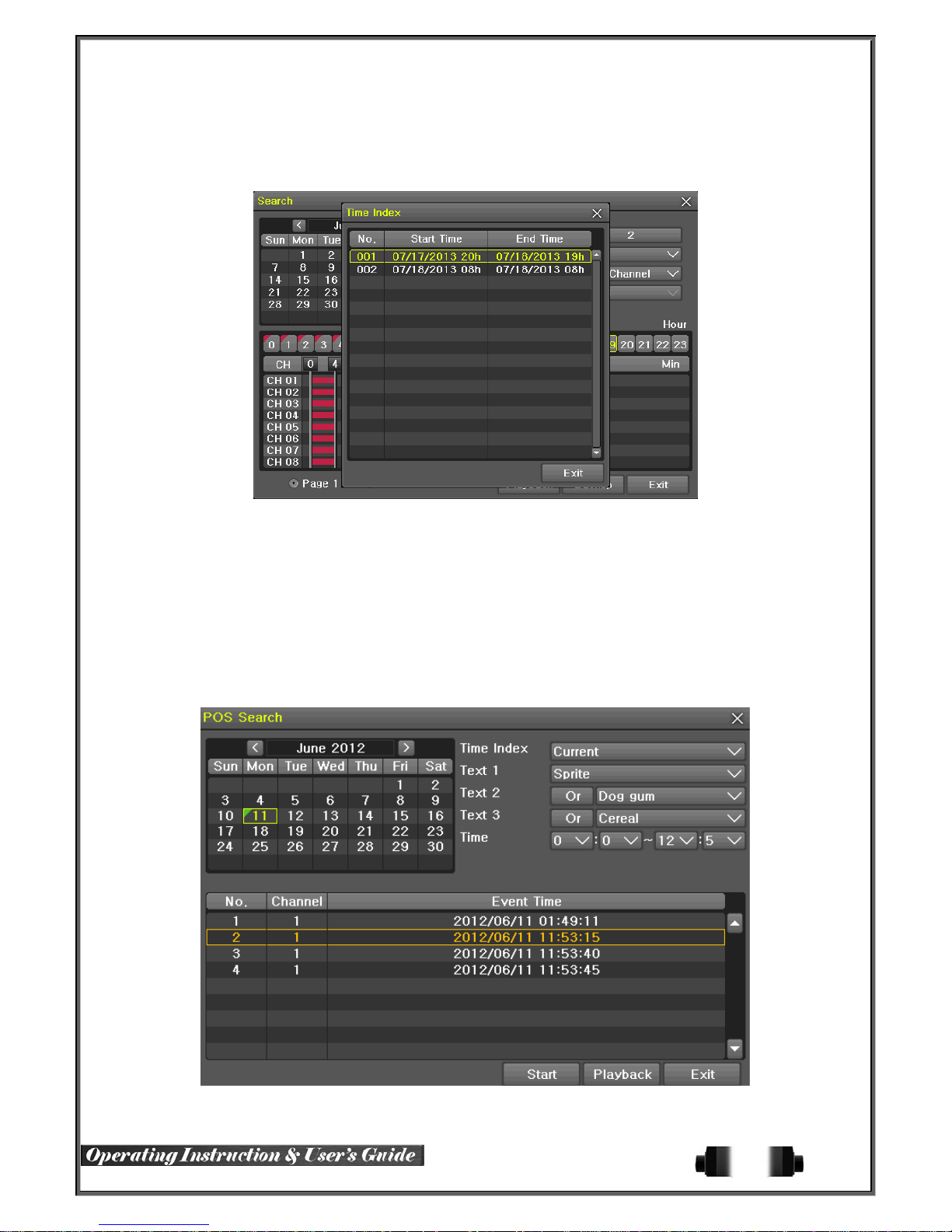
5-7-8List All
To check Time index in order of time line.
[Figure 5-31. Time Index]
5-8 POS Search
5-8-1POS Search Mode
On the real-time monitoring screen, select {Menu} {Search} {POS Search} and then a searching
window pops up as shown below.
5-8-2Year/Month/Day/Text/Time Selection
Please select date/time, Time index, Text 1~3, and select the start time within the channel..
5-8-3Search / Playback
After selecting the ‘Start’ Button, ‘1 searc hed item’ needs to be selected in order for ‘playback’ to start.
[Figure 5-32. POS Search]
43
Page 45
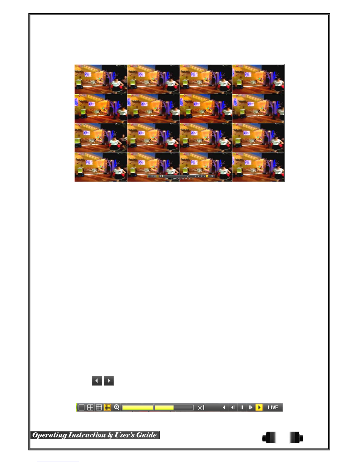
5-9 Playback
[Figure 5-33. Playback Screen]
※ There are five routes to play the recorded image.
Playback in the Calendar Search
Select {Playback} in {Menu} {Search} {Calendar Search} {Search}.
Playback in the Go To The Last
Select {Menu} {Search} {Go to The Last}.
Playback in the Go To The First
Select {Menu} {Search} {Go To The Firs t}.
Playback in t he Last Played Time
Select {Menu} {Search} {The Last Played Time}.
Playback in t he Log View
After selecting {Menu} {Miscellaneous} {Log Viewer}, select or double-click the time line lis ted to
play.
※ 960H-model series provide a variety of the playback.
Smart Search
POS Search
Calendar Search
Multi-Time
Multi-Day
Multi-Channel
Panorama Play
Event Play
Zoom Play
5-9-1Playback and Playback Speed Control
① In the Playback mode, the user can play back video contents by using buttons as shown belo
w.
② After the data is played to the end, the data of the next time zone will be automatically searched
and played (this function is possible only in the Multi-channel Playback mode; both backward playb
ack and forward playback are possible).
③
Pressing buttons, the user can adjust the playback speed by(ⅹ1) / (ⅹ2) / (ⅹ4) / (ⅹ8) /
(ⅹ16) / (ⅹ32) / (ⅹ300).
[Figure 5-34. Playback Status and Control Window]
44
Page 46
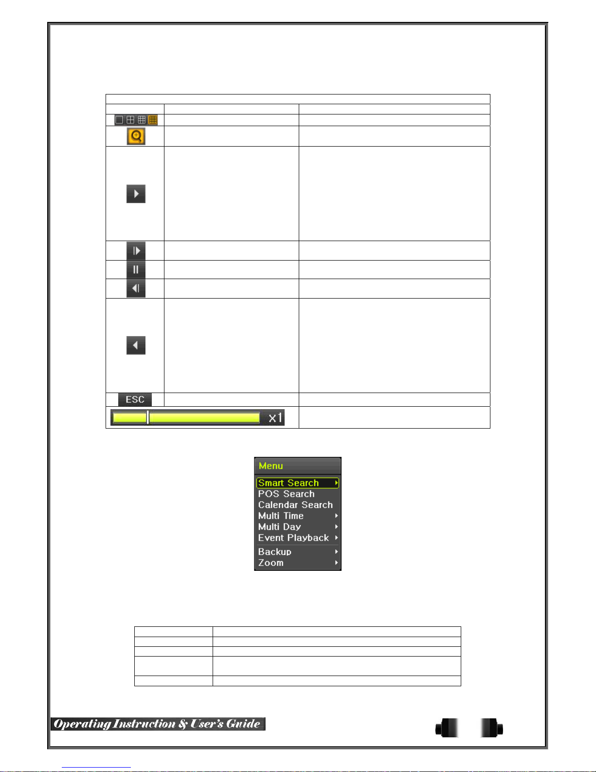
Description of the Search Buttons
Button Name Features
Channel Mode Change Sw itch the channel mode.
Zoom Mode Switch to the Zoom mode.
Forward Play / Fast Forward
Forward Frame by Frame
Pause Pause
Reverse Frame by Frame
Reverse Play / Fast Reverse
ESC Exit out of Playback Mode.
Selecting the right-mouse button or menu button in the Pla yback Mode pops up the {Playback Menu} as shown
below.
Press one time - Playback forward (ⅹ1)
Press two times - Fast forward (ⅹ2)
Press three times - Fast forward (ⅹ4)
Press four times - Fast forward (ⅹ8)
Press five times - Fast forward (ⅹ16)
Press six times - Fast forward (ⅹ32)
Press seven times - Fast forward (ⅹ300)
Pressing one more time in x300 leads to x1
back.
Playback frame-by-frame
Pause
Reverse playback frame by frame
Pause
Press one time - Playback reverse (ⅹ1)
Press two times - Fast reverse (ⅹ2)
Press three times - Fast reverse (ⅹ4)
Press four times - Fast reverse (ⅹ8)
Press five times - Fast reverse (ⅹ16)
Press six times - Fast reverse (ⅹ32)
Press seven times - Fast reverse (ⅹ300)
Pressing one more time in x300 leads to x1
back.
Status bar indicating information of the hourly
recorded image data and th e speed.
5-9-2 Smart Search
This function is used to searc h an image with the object mov ement at a specific zo ne quickl y. Searching by each
channel and a detail control are avail abl e.
Type Content
Sensitivity 5 levels; Lowest / Low / Middle / High / Highest
Minimum Mosaic pixel control available between 1- 10
Quick Search
Detail Search Search all frames.
[Figure 5-35. Playback Menu]
In the NTSC mode, search 30 frames once.
In the PAL mode, search 25 frames once.
45
Page 47
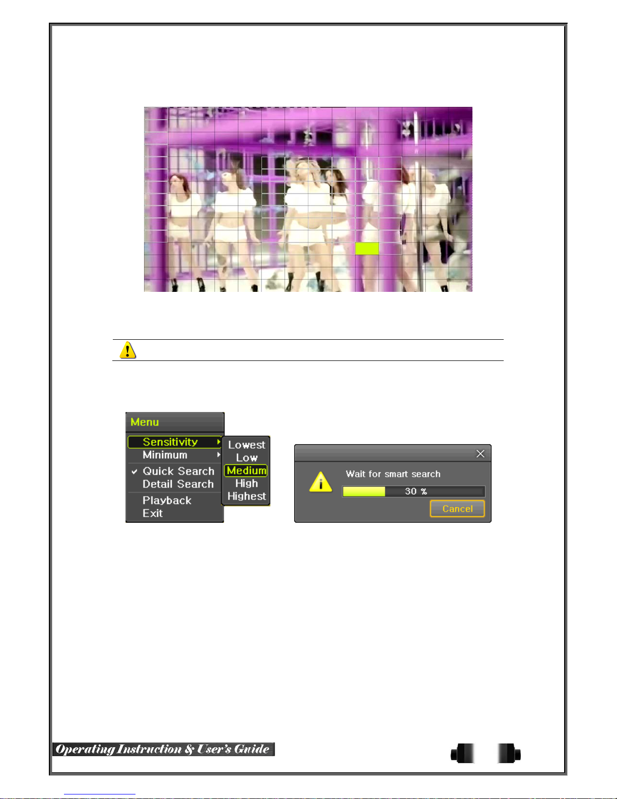
① Move to the Smart Search and select the desired channel.
② After shifting to the 1 channel mode, select areas to be smart searched.
[Figure 5-36. Smart Search Area Designation]
③ The 14 * 15 pixel mosaic mode appears. In the beginning, all pixels are selected. Designate an a
rea by left-click and drag the pixel mosaic pointer(deep yellow). Designate another area by repeatin
g the same way.
It detects motions in non-designated blocks.
④ Right-click brings up the menu as shown below. Configure each category and press the Playback
button to start searching.
[Figure 5-37. Smar t Sea rc h Mot i o n De te c tio n Window]
⑤ It may take time during the searching. Start the playback after searching.
5-9-3 POS Search
The Text Data recorded needs to be searched in order to Playback
5-9-4 Calendar Search
Move to {Menu} {Search} {Calendar Search} and then a searching window pops up.
5-9-5 MULTI TIME
The user can playback the video recorded image of the certain channel recorded in different time zones
simultaneously. The arrangement of the searching re su lt is the past to recent format.
5-9-6 MULTI DAY
The user can playback the vi deo recorded image of the certain channel recorded in different dates simultaneously.
The arrangement of the searching result is the past to recent format.
46
Page 48

5-9-7 MULTI CHANNEL
Multi-Channel Search is to play recorded images of the different channel over a certain designated time.
5-9-8 Panorama Play
Panorama Play is to pla y recorde d imag es of the c ertain c hannel frame b y frame . Panor ama Pla y ca n be v iewe d
at 16 frame / 8 frame / 4 frame / 1 frame.
[Figure 5-38. Panorama Playback]
5-9-9 Event
Event is to search and play events [ All/Motion/Sensor/Audio ].
5-9-10 Backup
The user can save the backup image data and capture the image into [CD/Externa l Device].
Backup Save the recorded data into [CD/External Device].
Snapshot Capture and save the current displaying screen.
5-9-11 Screen Mode
Screen division is available in the Playback mode as same in the Monitoring Mode.
[1 / 4 / 9 / 16 Mode] can be selected.
① Select the screen division mode by using the mouse or arrow keys in the front panel and rem
ote controller.
[Figure 5-39. Display Mode]
5-10 Log Viewer
DVR records all Log information over the system operation including Power on/off, System Setup and Network
Access. Move to {Menu} {Miscellaneous} {Log Viewer} to see the logs.
47
Page 49
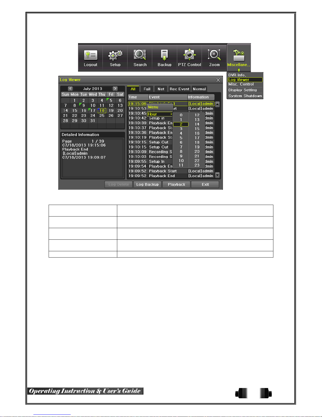
[Figure 5-40. Log View]
5-10-1 Log Type
General
Recording Event
Network
Fail
All Logs related to all system operations
Logs related to power ON/OFF, file copy/backup failure, setup start/end,
playback, and other basic system operations
Logs related to the recording including motion detection and sensor
detection, Audio detection
Logs related to network operations including network login, network
logout, and network live
Logs related to system operation failures including signal loss and
network connection failure
5-10-2 System Log Viewer
① In the real-time monitoring mode, {Menu} {Miscellaneous} {Log Viewer}, then, Log List Windo
w pops up.
② On the activated calendar window, select the desired date (year/month/day) by using the arrow key
s and the Select button.
③ The user can check the time and the log type by using the arrow keys in the log list.
④ Use the Up/Down button to check the logs by time and type on each page.
⑤ The user can shift the focus to a certain time zone to play the certain time (playback will start fro
m the time point when logs are saved)
⑥ Click the right-mouse button or select {Menu} button in the front panel and select {Hour} to move
the desired log time zone.
48
Page 50

[Figure 5-41 . Move to the log list of the certain time zone in Log View]
Time Changed Log Da ta View
The stored data folder is created each time the user changes the time. A Vertex Vault triangular
icon is displayed at a date in the calendar window that time changes are made. Otherwise, a red
triangular icon is displayed at an unc hanged date. To view the log details, select the desired
date with a red icon. Selecting a date with the Vertex Vault icon causes the changed date list
window to appear.
5-11 Recording
5-11-1 Recording Types
It supports various recording types as shown below.
Recording Type Description
Continuous The Contin uous recording will be initiated based on the general frame rate.
Motion When motion is detected, the recording wil l be initiated based on the event frame value.
Sensor
Audio When audio is detected, the recording will be initiated based on the event frame value.
Text When a text is received from POS device, the text will be recorded.
When input signal from an extern al sensor is generated, the rec ording will be initiated
based on the event frame value.
5-11-2 Recording Setup
Go to {Menu} {Setup} {Recording} for the Recording Setup. For more information, move to {Menu}
{Setup} {Recording}} {Recording}.
5-11-3 Recording Status View
(1) Recording Status by Color
Recording
Event
Recording
Mode
※ Recording Event / Recording Mode Icon ※
Motion Detection Recording
Sensor Recording
Audio Recording
Text Recording
Video Recording
Audio Recording
Text Recording
49
Page 51

5-12 Backup
In order to backup the d ata, make sure to check that either internal or external storage devices (C D, DVD or
HDD) supports USB 2.0 is connected. For supported external devices, refer to Appendix. The user can back up
data in the real-time monitoring, search, log, or the playback mode.
5-12-1 Backup in The Real-Time Monitoring Mode
① In the real-time monitoring mode, select {Menu} {Backup} {Backup}. The backup menus will
then appear.
② The automatic backup time is set to 5 minutes before the Copy (Backup) button is pressed, and
the end time, to the time the Copy (Backup) button is pressed.
③ All channels containing data at the time of backup are backed up automatically. Depending on the
divided screen mode, however, only those channels that can be viewed may be selected.
④ For the remaining backup procedures, see [5-33 Common Backup Procedure].
5-12-2 Backup in Search Mode
① Select {Menu} {Search} {Calendar Search}.
② Click the right-mouse button or select {MENU} button in the front panel.
③ The automatic backup start time is set to the year/month/date/hour/minute set in the search mode,
and the end time, to the last minute/second of the data existing at the selected time.
④ All channels with existing data at the time of backup are backed up automatically.
⑤ For the remaining backup procedures, see [5-33 Common Backup Procedure].
5-12-3 Backup in Log Mode
① Select a date in {Menu} {Miscellaneous} {Log Viewer} and select a log related to the data
to be backed up.
② Click the right-mouse button or select {MENU} button in the front panel.
③ The automatic backup time is set to 5 minutes before the selected log is generated, and the end t
ime, to the time the selected log is generated.
④ All channels with existing data at the time of backup are backed up automatically. If a log has
been generated for a specific channel, however, then only that channel is selected.
⑤ For the remaining backup procedures, see [5-33 Common Backup Procedure].
5-12
-4 Backup in Playback Mode
① In the Playback mode, select {Menu} {Backup}. Any playback in progress at this time will stop.
② The automatic backup time is set to 5 minutes before the Copy (Backup) button is pressed, and th
e end time, to the time the Copy (Backup) button is pressed.
③ All channels containing data at the time of backup are backed up automatically. Depending on the
divided screen mode, however, only those channels that can be viewed may be selected.
④ For the remaining backup procedures, see [5-33 Common Backup Procedure].
50
Page 52
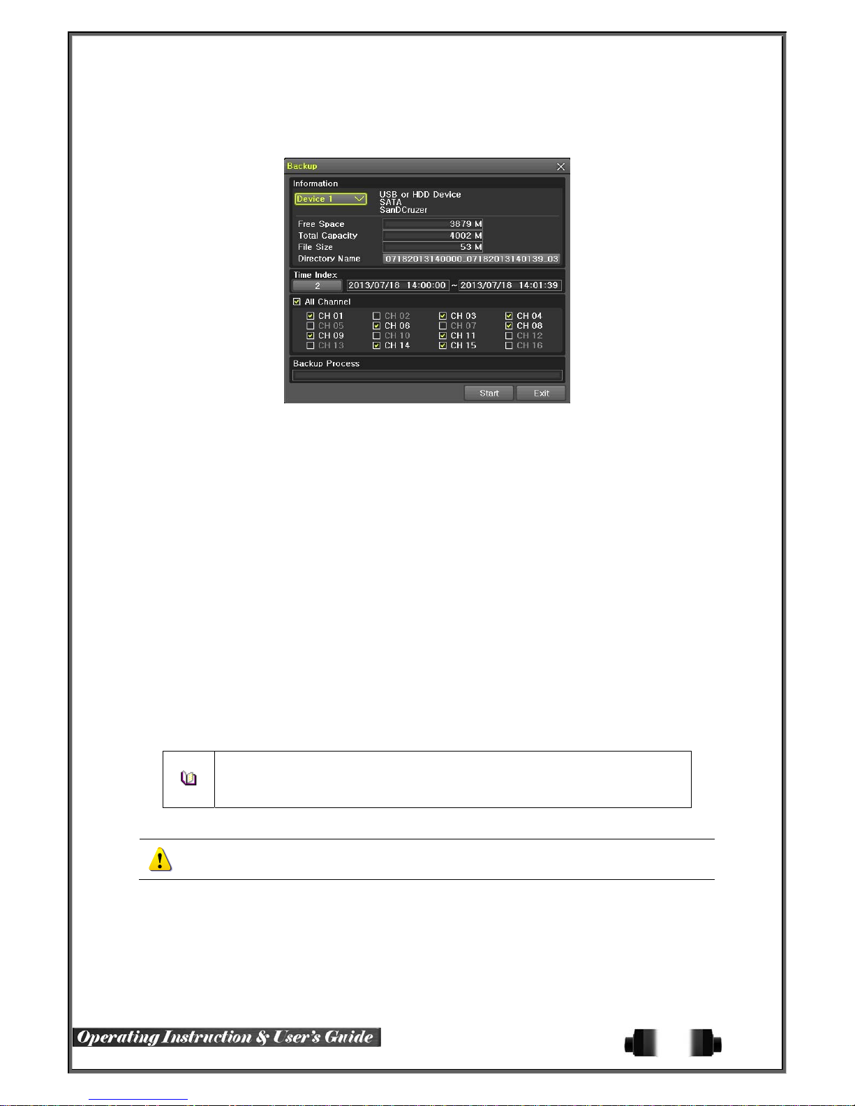
5-12-5 Common Backup Procedure
[Figure 5-42. Backup Window]
① [Figure 5-34] shows the initial backup window menus.
② A list of the devices that can be selected is outputted with simple information of the currently selec
ted devices
③ Selecting a device by pressing the Select button causes the free space and total capacity for the
selected device to be displayed.
④ Selecting a device causes the directory name based on the initial values for the time and channel
to be displayed and the size of the file to be backed up to be calculated.
⑤ The directory is named as same with the backup time. The first 12 digits are determined by the y
ear/month/day/hour/minute/second for From, and the 12 digits in the middle, by the year/month/day/
hour/minute/second for To. The last 2 digits are determined by the number of folders in the selecte
d device.
⑥ Selecting a device enables selecting the backup time as well. As a rule, the From time cannot be
later than the To time, and the To time cannot be earlier than the From time.
⑦ To change the start and end time, press the Select button after choosing the start and end time.
Change year/month/day/hour/minute/second by using arrow keys and press the ESC button.
⑧ Changing the backup time causes the name of the directory to be backed up to be changed as w
ell.
⑨ If the file to be backed up exceeds the free space, its size is displayed in a yellow box in case th
e selected device is capable of rerecording and in a red box if not.
If the backup storage device is not formatted, in case the box displaying the size of the
file to be backed up is displayed in yellow, and if backup is executed by pressing the
Copy (Backup) button, a prompt asking(Yes/No) whether to erase the device will appear.
Selecting {YES} causes the storage medium for the selected device to be erased.
⑩ Press the Copy (Backup) button. A prompt asking(Yes/No) whether to proceed with the backup.
※ Select [Yes] to back up the data or [No] to stop the backup. Otherwise, press the [Cancel]
button to return to the device selection mode on the backup window.
⑪ Select {Yes} to continue the backup.
5-13
Setup Backup
The Setup Backup is to back all setup values of the current menu up. This function enables the user to copy the
setups and apply them into other devices.
51
Page 53

[Figure 5-43. Backup and Sub-menu Setu p Backup]
① For the Setup Backup, a device for backup must be connected.
② Move to {Menu} {Backup} {Setup Backup} and a window shown below appears. The setup
is copied by the name shown below.
[Figure 5-44. Setup Upgrade]
Saved as the name below.
①Model ② DVR name ③ Version ④ Date ⑤ Time
③ Move to {Menu} {Setup} {System} {6. Upgrade} ->{Setup} after insert the backup devic
e.
④ With this way, the user can upgrade a new device with the current setup values in easy way.
5-14 Log Backup
This is to back logs up including General/ Recording Event / Network / Fail.
① Move to {Menu} {Backup} {Log backup} and start the backup process after selection of the
events.
.Log files are created at a folder shown below.
565645348945_20100303.log
[Figure 5-45. Log Backup]
52
Page 54

.log file is the text file.
5-15 Capture
The Capture function lets the user create a JPG file in the real-time monitoring, playback, search, or log mode
and back up the image data.
① To back up the currently displayed image, select {Menu} {Backup} {Capture} in real-time
monitoring, Playback and Log mode.
② When only one USB2.0 backup device (excluding ODD devices) is searched, the JPG file is stored
in the same device.
③ If there are no or more than two USB2.0 storage devices (excluding ODD devices), a window for
selecting the device will be displayed.
④ If the selected device is an ODD device, a prompt asking whether to back up in the ODD device.
53
Page 55
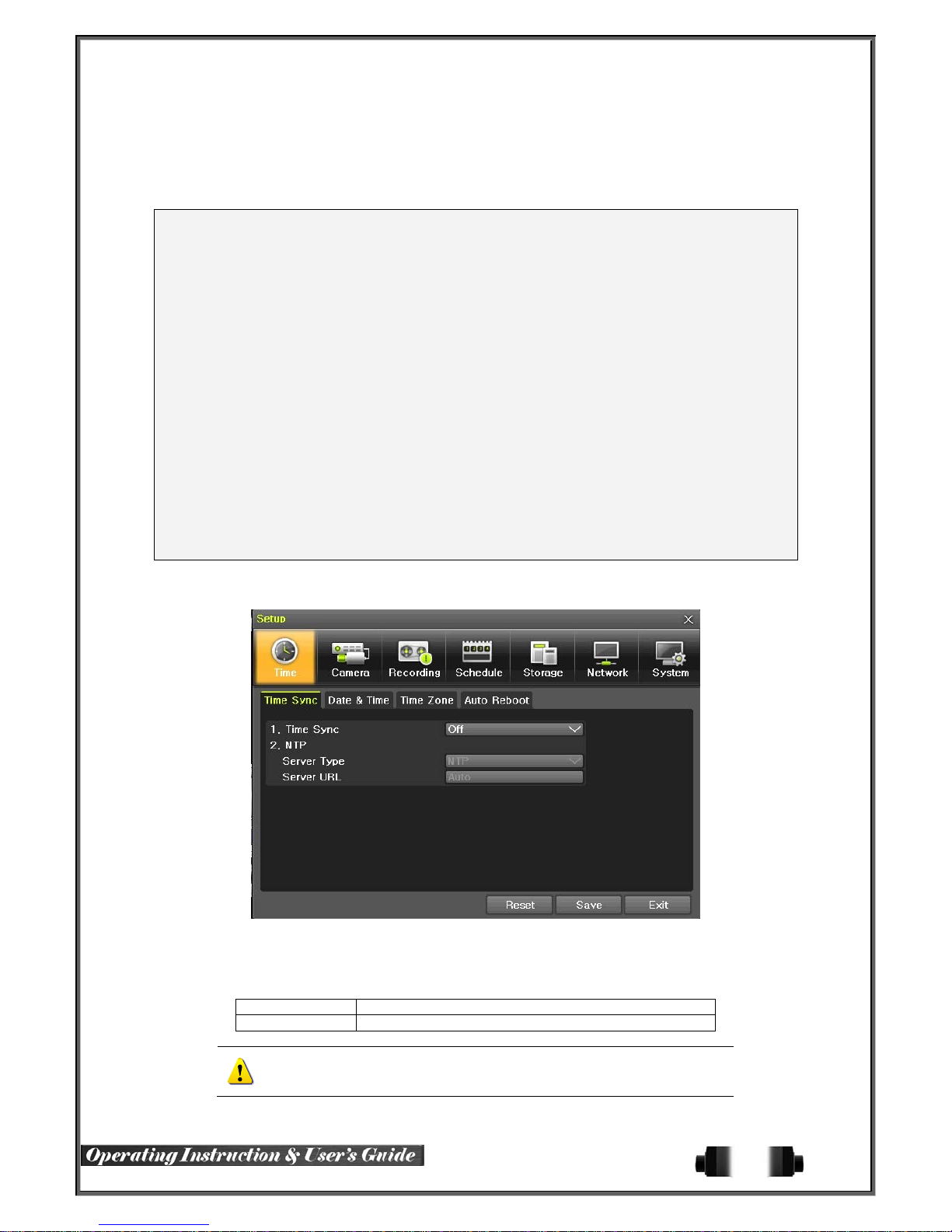
Chapter 6. Setup
6-1 Time
※ Function Description
1. Time Synchronization
1) Synchronization with the NTP server
The time is synchronized once every hour with the NTP Server.
A. Automatic Setup
The nearest server from the user’s zone will be selected for connection. If the connection fails, the next
nearest server will be chosen.
B. User Setting
The user sets the URL or IP for the NTP server. If connection is not established , a message will be s ent to
the user , and the related log, saved.
If synchronization with the NTP server fails, synchronization with RTC will be established.
2) Synchronization with the DVR Time Server
The DTS server is executed in the DVR system and the time is synchronized every hour. DTS clients of
DVR series referring to the DTS synchronize the time of the DVR system with DTS.
When the DTS time or a zone is changed, the change is reflected on DVR series belonging to the network
(the synchronization signals are broadcast ed witho ut passing throu gh th e router or gate wa y). The DVR time
server does not support automatic connection.
2. Daylight Saving Time (DST) Setup
Regardless of whether NTP server or DST server is referred to, DST is automatically processed according
to the time.
3. Time Setup by User
The user can set the time directly.
For the NTP client setup, the user can read the time but not change it.
※ Move to {Menu} {Setup} {Time} to set up time functions.
6-1-1 Time Sync
① Select Time Sever / Sever Type / Sever URL.
Off The time server is not used.
NTP NTP is used to set the time for the time DVR.
{NTP} setup is available when {Time Sync} is set as NTP.
The user can enter the IP only when the server type is DVR. For
the NTP server, Automatic, IP, or URL should be selected.
[Figure 6-46. Setup / Time Menu]
54
Page 56
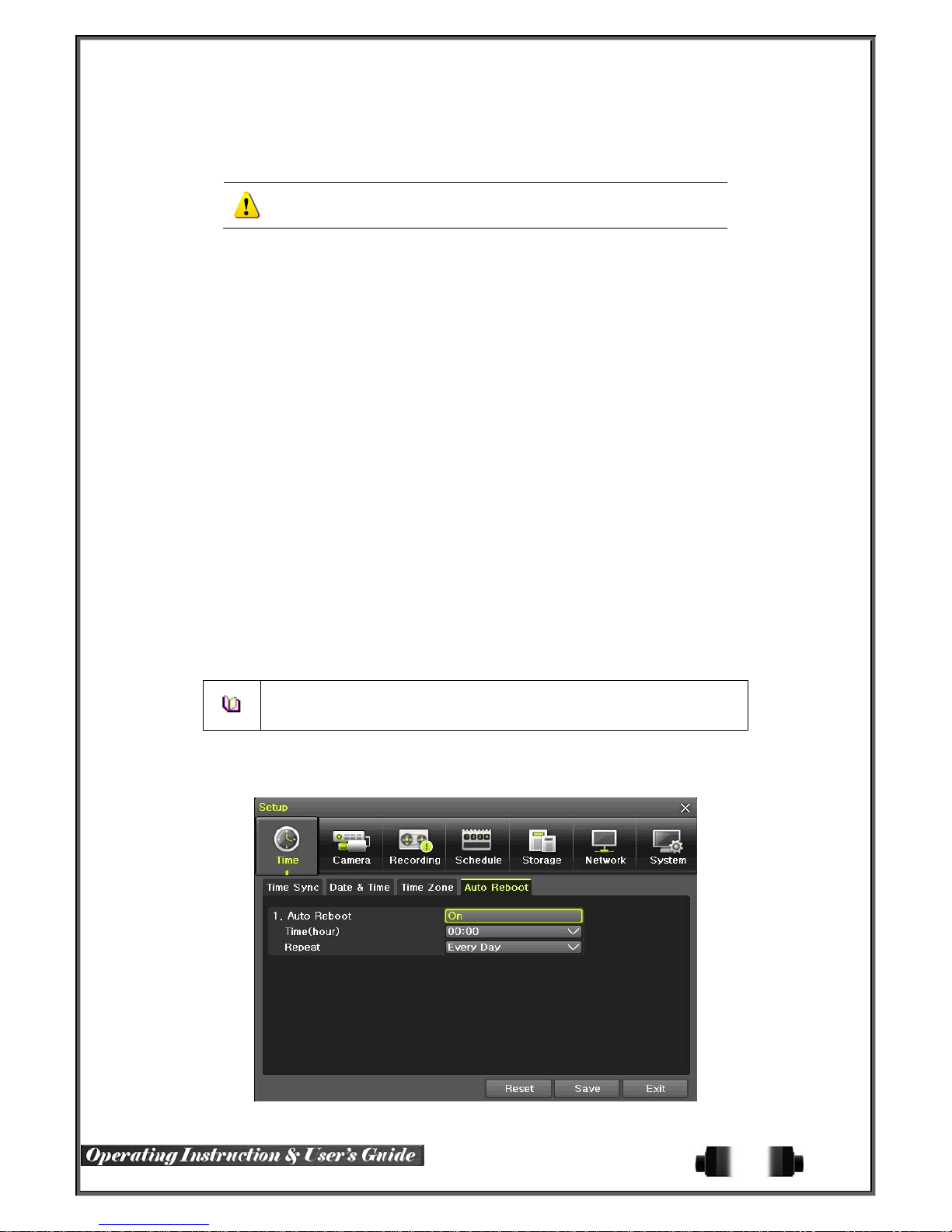
6-1-2 Date and Time
(1) Date and Time
Only available when Time Server is off.
The system date and time format is Year/Month/Day Hour/Minute/Second.
① By using the arrow keys and the Select button, move the focus onto the desired field; Year/Month/
Day Hour/Minute/Second and press the Select button.
② Select a field you want to change by using the arrow buttons and press the Select button.
(2)Time Display Format
Select Time Display Format among [Day/Month/Year] / [Month/Day/Year] / [Year/Month/Day].
6-1-3 Standard Time Zone
(1) Standard Time Zone
① Select {Standard Time Zone}.
② On the selection window, select the standard time zone you want to set.
(2) DST
① By using the arrow keys and the Select button, select {Summer Time}.
② On the selection window, select On/Off by using the arrow keys and the Select button.
(3) Start Time
① By using the arrow keys and the Select button, select {Start Time}.
② On the selection window, set up Start Time by using the arrow keys and the Select button.
(4) End Time
① By using the arrow keys and the Select button, select {End Time}.
② On the selection window, set up End Time by using the arrow keys and the Select button.
※ For a weekly setting in the {Start Time} and {End Time} fields, set Day to 0.
※ After the Daylight Saving Time is selected, the existing data will be displayed
as “OLD_” in the search and log list.
6-1-4 Auto Reboot
Auto Reboot is for system stability, rebooting itself regularly.
[Figure 6-47. Setup / Auto Reboot Menu]
55
Page 57
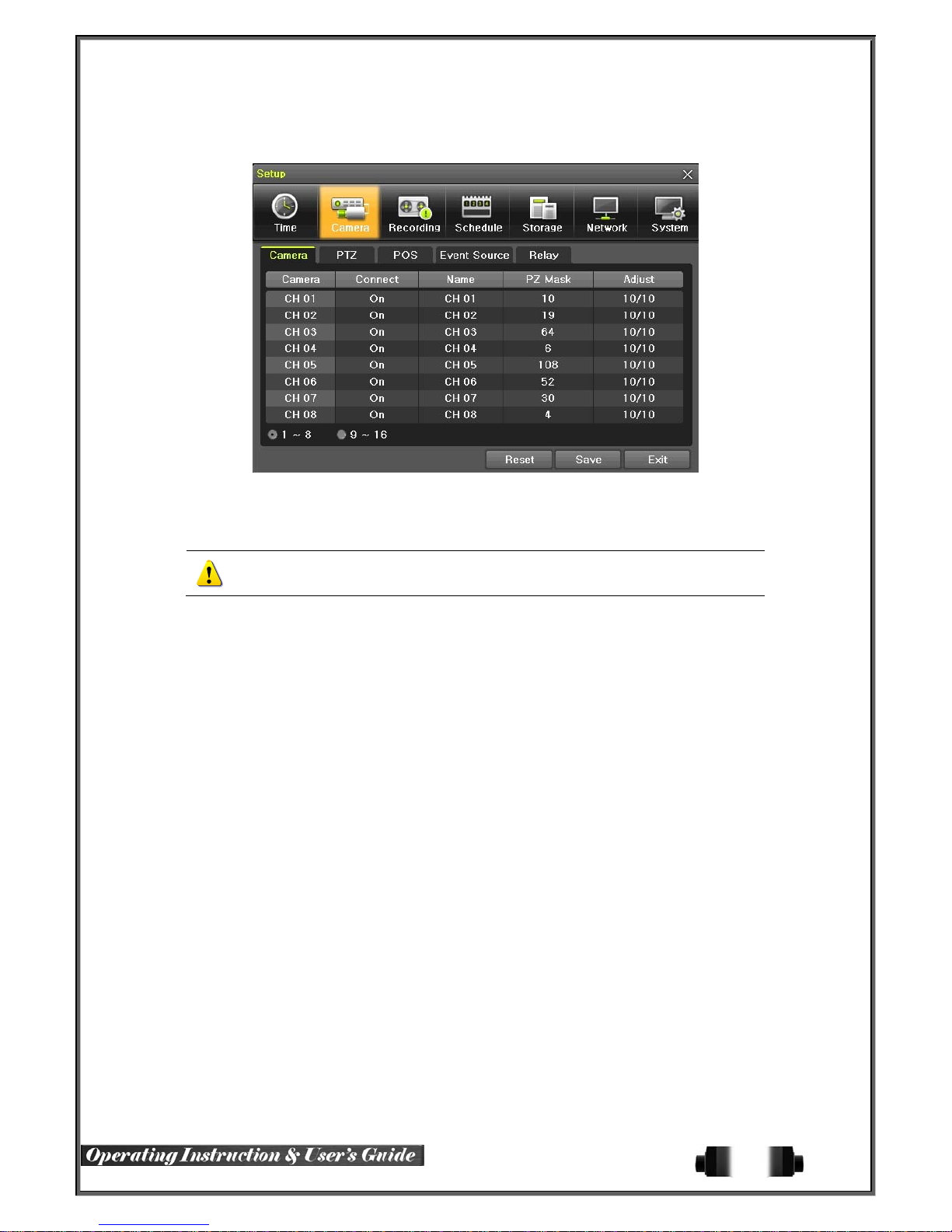
6-2 Camera
[Figure 6-48. Setup / Camera Menu]
6-2-1 Camera
① Connection
Used to set whether to connect or disconnect each camera channel.
※ When the camera channel is set to disconnected, the video contents will not be
displayed even if the camera is actually connected.
② Title
Name each camera. Max. 20 letters are available.
③ PZ Mask
Used to hide a certain area of the real-time monitoring screen. After sel ecting PZ Mask over each channel, it
becomes the 1 channel division mode and designate sections where you don’t want to monitor.
④ Adjust
Adjust Brightness/Contrast/Color/Saturation/Sharpen/Camera.
6-2-2 PTZ
Setup the protocol and baud rate of the PTZ Camera.
6-2-3 POS
Setup the protocol and baud rate of the POS device.
6-2-4 Event Source
Select {Menu} {Setup} {Camera} {Event Source}.
(1) Motion Area
The user can setup the m otion detection area. Area setup related to motion can be decided.
56
Page 58
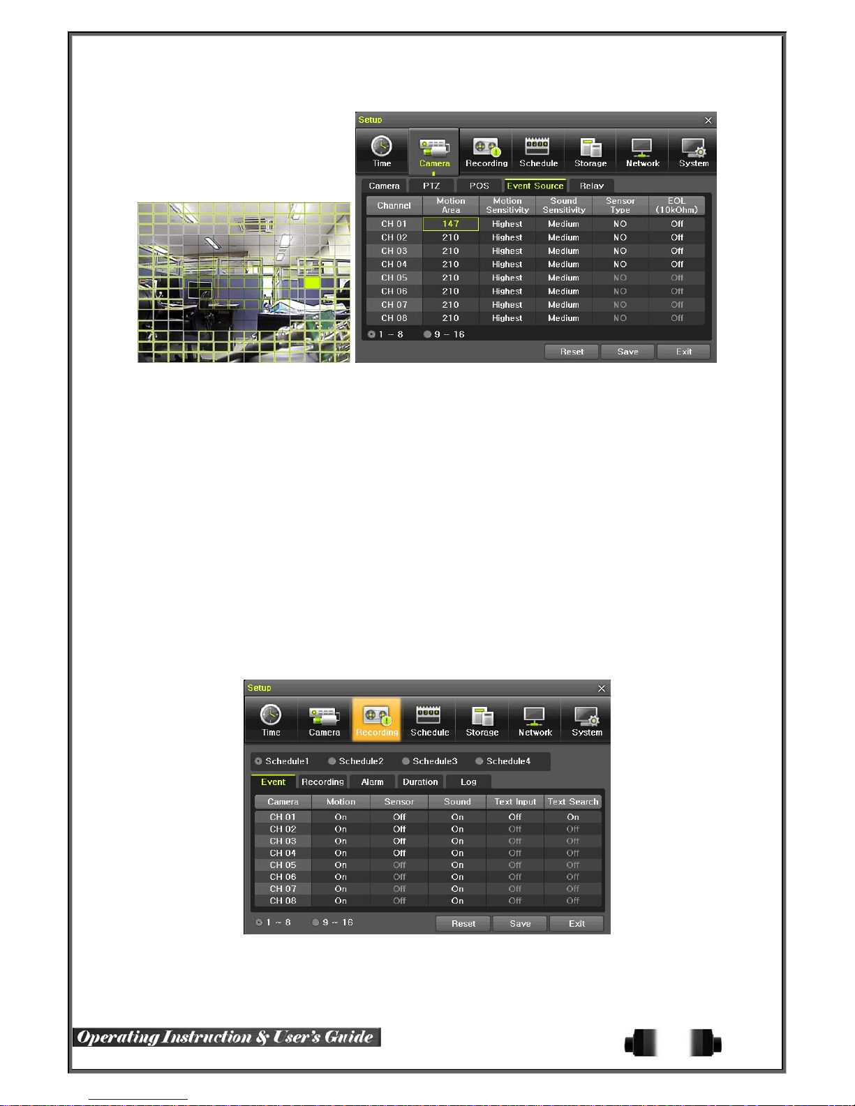
[Figure 6-49. Motion Area Setup]
① Select Motion Area of each channel.
② It becomes the 1 channel division mode and rectangular boxes appear where motions occur. Drag
the yellow pixel cursor by using the mouse or the front button/remote controller and select pixels w
here motion detection doesn’t applied. The selected area turns brown.
③ Select Exit to finish.
(2) Motion Sensitivity : Lowest/Low/Middle/High/Highest.
(3) Sound Sensitivity : Lowest/Low/Middle/High/Highest
(4) Sensor Type : Select the sensor type.
(5) EOL : EOL Function Select (On / Off).
.
6-2-5 Relay
Select the relay type.
6-3 Recording
The Main setup is to configure the environment of record and system and major functions.
In the real-time monitoring, move to {Menu} {Setup} {Recording}
[Figure 6-50. Setup / Recording]
57
Page 59
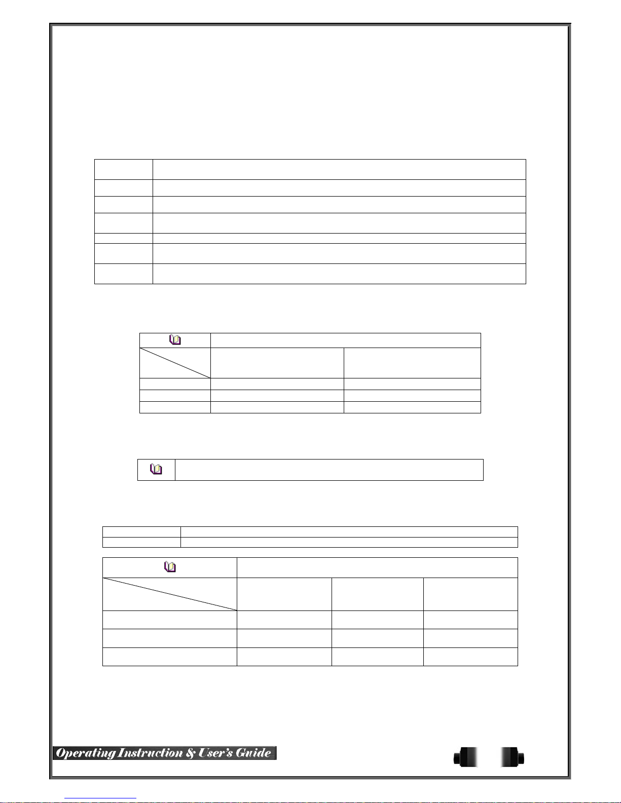
6-3-1 Schedule Selection (Schedule1 ~ Sched ule4)
① Each channel can be scheduled in 4 different schedules. This schedule can be set as the
recording schedule and each time can be 4 different schedules.
6-3-2 Event
This is to set the events On/Off of Motion / Sensor / Sound / Text Input / Text Search.
Recording
Type
Continuous Continuous recording based on the Normal Speed frame rate.
Motion When motion is detected, recording will be initiated based on the event frame rate.
Sensor
Sound When audio is detected, recording will be initiated based on the event frame value.
Text Input
Text
Search
When input signal from an external sensor is generated, recording will be initiated based on
the event frame value.
When a text is received from POS device, recording will be initiated based on the even t frame
value.
When searching Text, can select to receive email regarding the ‘Word’ that is set..
Description
6-3-3 Recording
(1) Recording Resolution
Used to set the resolution of the recorded channel.
Resolution
CIF
D1
960H
Type
352ⅹ240 352ⅹ288
704ⅹ480 704ⅹ576
960ⅹ480 960ⅹ576
Resolution by Video Type
NTSC PAL
(2) Recording Quality
Used to set the quality of the recorded video. Select among five levels {Lowest} / {Low} / {Middle} / {High} /
{Highest}.
※ The higher picture qual ity, the bigger file size.
(3) Frame Rate
If the user configures Normal Speed and Event Speed at the same time, the continuous recording follows Normal
Speed frame rate and the event recording follows Event Speed frame rate.
Normal Speed Set the recording frame rate for Continuous recording.
Event Speed Set the recording frame rate for Motion, Sensor, Audio, Text
Maximum Recording Frame by Resolut io n
Model
Resolution
16CH 480/400fps 480/400fps 480/400fps
8CH 240/200fps 240/200fps 240/200fps
4CH 120/100fps 120/100fps 120/100fps
(4) Audio
Used to set the recording of the external audio input linked to the system.
CIF
(NTSC/PAL)
D1
(NTSC/PAL)
960H
(NTSC/PAL)
58
Page 60
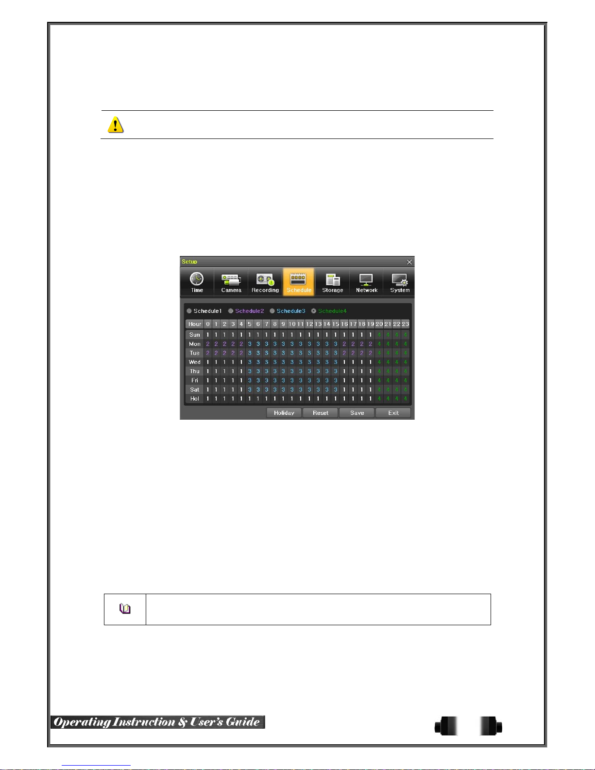
6-3-4 Alarm
※ This function is used to gener ate alarms through the B uzzer / PTZ Preset / e-m ail / Relay / Spot / Popup in
case of an event. PTZ preset can be configured between 1-16.
※ Popup function is to inform event occurrence to the user through a warning windo w in the
6-3-5 Duration
Setup Pre-Recording( On / OFF ), Post-Recording(5 / 10 / 15 / 20 / 60 / 150 / 300 seconds).
※in Pre-Recording, images of the last 7 seconds before the event occurrence are recorded.
real-time monitoring mode.
6-3-6 Log
Setup On / Off for Motion / Sensor / Sound / Text Input.
6-4 Schedule
H-model series provide 4 different recording mode conf igurations. Each sched ule mode can be set one week/24
hours and the recording f ollows the setting automatically.
[Figure 6-51. Schedule Wi n dow]
6-4-1 Schedule Setup
Select one schedule among Schedule1, Schedule2, Schedule3 and Schedule4.
(1) Selection Tip
① Select the day and time to be set by using the arrow keys.
② Select after moving the cursor onto Time(0-23) or Day(Sun. – Holiday) then the user can configure
the whole line at once.
③ Using the mouse can be easier.
(2) Holiday Registration
This feature is used to enable the user to set th e hol id ays and schedule independently.
① Move to {Schedule} {Holiday}.
※ If the date for the holiday and day of the week are the same in the {Schedule} menu,
the holiday setup will have priority over the date setup.
※ Designated holidays ar e mark ed with a red tag.
② On the Holiday Registration Window, select the date by using the arrow keys and the Select butto
n and press the Select button.
③ After setting the holiday, move to {Save} at the bottom of the menu. Afterward, press the Select b
utton.
59
Page 61
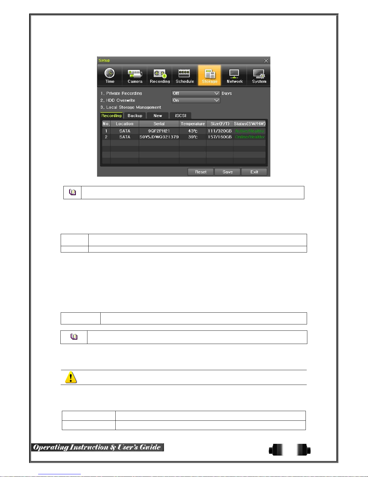
6-5 Storage
[Figure 6-52. Storage Window (Local)]
In the St orage menu, T o apply the new setting, save the new setting after changing the setting.
Reset: Initialize the menu to the basic setting.
6-5-1 Max. Recording Days
This is to limit the recordi ng days. You can set None/1day/7days/30days/User setting(1-31).
6-5-2 HDD Overwrite
① Select On/Off for HDD Overwrite.
On
Off If there is no more hard disk space left, the further recording will not be executed.
If there is no more hard di sk space left, the existi ng files will b e overwritten by startin g with
the oldest.
6-5-3 Local Storage Management
(1) Local Storage Management Function
Local Storage refers to the internal hard disk and storages connected to the system via USB. Local Storage is
classified and managed as {Recording}, {Backup}, {New}, {iSCSI} and functions are described below.
① Recording
The Recording storage is managed in Direct. The Recording storage stores dat a on the hard disk in the real time.
Five commands can be executed. Depending on the S/W status, however, some commands cannot be executed.
New
Returns the status of the selected storage device to New; if this command is executed,
the selected storage device will be moved to the {New} storage device manager.
※ Physical states supporting the execution of the commands abo ve includes Healthy and
Warning. In fault state, however, no command can be executed.
② Backup
The backup storage is managed in Backup. Backup storages are not used to store data; rather, they a
re only used to back up the data. The user can execute only the {New} command.
Depending on the storage type, the storage is used only for (Recording) or (Backup) purposes.
③ New
All storages, initially detected are managed in {New}. All initially detected storages are displayed as N
ew and can be changed into Recording storage or Backup Storage.
Recording-Format Changes the selected storage into a dedicated recording storage.
Backup-Format Changes the selected storage into a backup storage.
60
Page 62
In {New}, At least, one storage shall be selected as a dedicated storage. Otherwise, the data
cannot be stored in the real time.
① iSCSI
iSCSI HDD Setting. (Please refer to ‘6-6-6’ for more details)
(2) Composition of the local storage device
Active Connected to storage or backup device; currently saving the data.
Online Only connected to storage or backup device.
Offline Not connected to storage or backup device.
Healthy Connected to storage or backup device; functions normally.
Warning
Fault Not connected to storage or backup device; cannot perform data saving or backup.
1. Fault State : The storage device is completely damaged, and none of the S/W operations
can be performed. The fault state is not related to a DVR problem. The DVR has detected the
fault and stopped the recording.
2. Warning State : The storage device has a physical error that can be corrected by the storage
device or by the DVR. If the error is not taken care of, how ever, the storage device is likely to
be damaged (and shift t o fault state). Backing up data in the corresponding storage device
and replacing the device with a normal one are strongly recommended.
3. If there is an active storage device with a warning or a fault, a message is displayed on the
upper left part of the screen.
(3) Instruction when adding the local storage device
Connected to storage or back up device, but error was detected; in t his case, data
storing or backup cannot be made (fo r more inf o rm atio n, see the description below).
※ There are three software status types.
※ There are three hardware status types.
① Open the system body and install a new disk (connect the data cable and the power cable)
② Connect power to the system and boot the system.
③ Select {Menu} {Setup} {Storage} by using the arrow keys and the Select button.
④ A newly displayed disk will then be displayed as {New}.
⑤ Select a newly installed disk by using the arrow keys and the Select button and initialize the disk
as a {Recording} or a {Backup} disk. The following describes the method of setting the recording st
orage.
⑥ {Recording} shows the status of the newly installed disk online.
※ Selecting {Recording-Format} or {Backup-Format} causes all data in the device to
be erased. Therefore, caution is required.
※ While {Recording-Format} or {Backup- Form at} is being set up, do not remove the
device (may cause an error when detecting the device).
※ To use the external or portable storage device for system upgrade, set to {BackupInit} in the {New} item for {Main Setup} {Storage Device} {Local Storage Device
Management}.
※When used in DVR equipment for the first time, a backup USB device will always be
detected in the {New} category. Therefore, a USB device in the {New} category must be
set up as {Backup-Format} prior to use for backup. A USB device that has gone
through this procedure will be detected in the {Backup} category when used again in
the DVR equipment.
61
Page 63

(1) How to changed FAULT HDD
① Check Faulty HDD number
② Turn OFF unit by power button.
③ Detach cover of DVR
④ Find the faulty HDD by number printed on mainboard
⑤ Detach the faulty HDD
⑥ Attach new HDD.
⑦ Attach cover of DVR
(2) HDD Format for Recording
Select the model first.
As shown below, proceed with the following order {New} {Recording-Format}.
6-6 Network
[Figure 6-53. Setup Network Window]
6-6-1 Ethernet
(1) TCP/IP
This is to use a fixed IP in the Local Area Network environment.
① Select {Ethernet} in {Menu} {Setup} {Network}.
② Select {TCP/IP}.
③ Save after filling in IP Address, Subnet Mask, Default Gateway, Primary DNS, and Secondary DNS
.
6-6-2 DDNS
As part of the DNS system, the Dynamic Domain Name System (DDNS) service updates IP addresses of the
host name in the real time an d alloc ates fi xed domain names to syste ms lin ked to dynamic IP address es to all ow
users to use the same DNS name regardless of the change of in the IP address.
It provides dynamic DNS to ensure URL access in the dynamic IP environment.
User can monitor the remote place thru internet with web server functions which is equipped in DVR.
① Select On/Off of DDNS or a domain name to use by using arrow keys and the selection button.
② In case of DDNS On, enter the host name and save it then, the registration procedure of the host
name proceeds automatically. You can enter the host name with 4-20 letters.
③ The host name to enter must not be pre-registered in DDNS sever. Otherwise it won’t work.
④ The basic host name is the MAC address of appertaining DVR.
⑤ In case the host name have entered starts with “000c28”, none of MAC address will work
62
Page 64
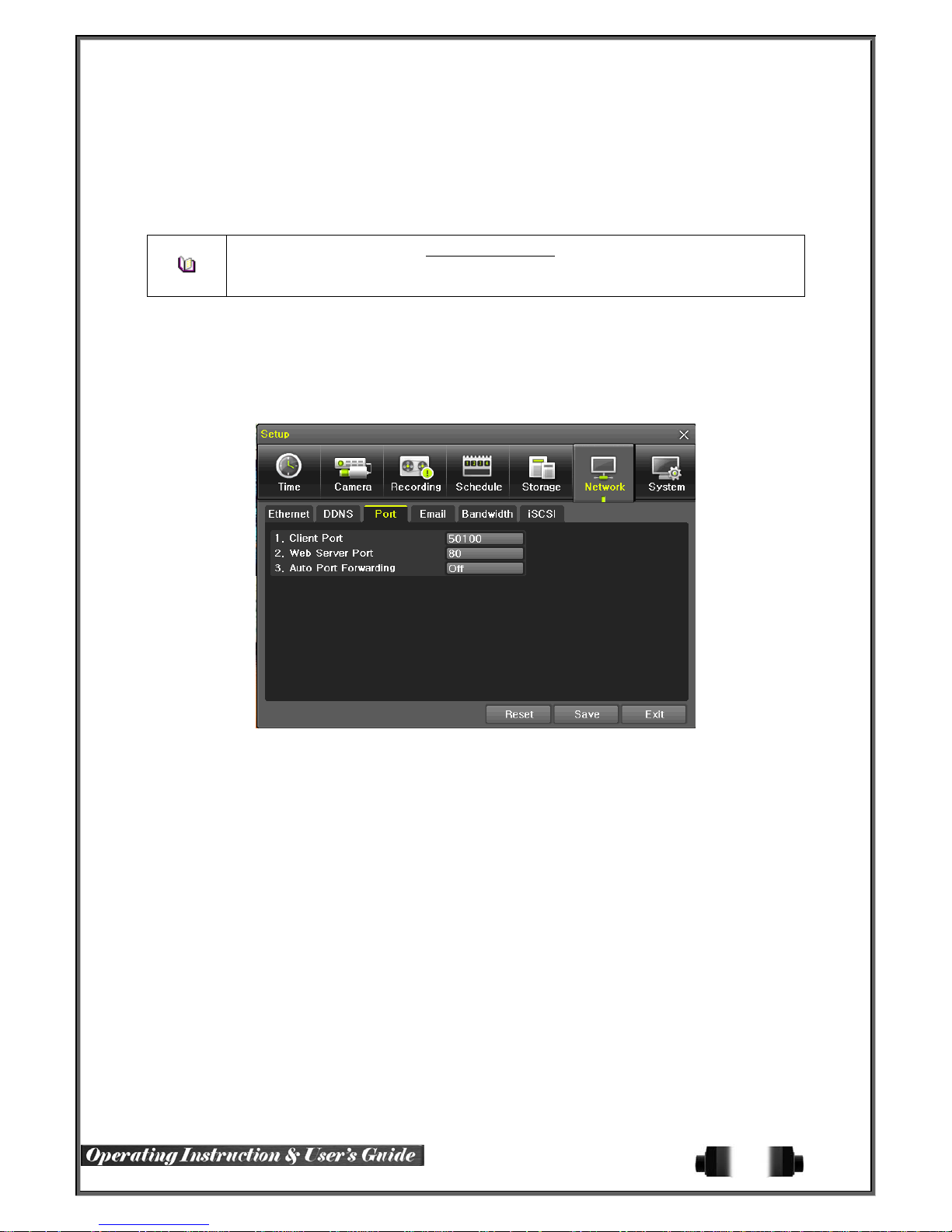
excepting for appertaining DVR’s.
⑥ In case of DynDNS On, enter the host name, user name registered in DynDNS and password the
n, save them.
※ Access to DynDDNS sever(http://www.dyndns.org) and apply for the user account then,
register the domain name to use and enter URL.
※ For more information, please access to the site.
6-6-3Port
Move to {Menu} {Setup} {Network} {Port}.
This feature is used to set the network port.
The default value is 50100; a randomly chosen value can be used depending on the network environment. The
Web Server Port is used to connect the DVR remote monitoring. The Web Port Default is 80, but can be set
between 2000 ~ 65527.
[Figure 6-54. Net work Port Window]
6-6-4 E-mail
① Move to {Menu} {Setup} {Network} {E-mail}. To use the e-mail function, DNS or sub
DNS in {Menu} {Setup} {Network} {Ethernet} need to be configured.
63
Page 65
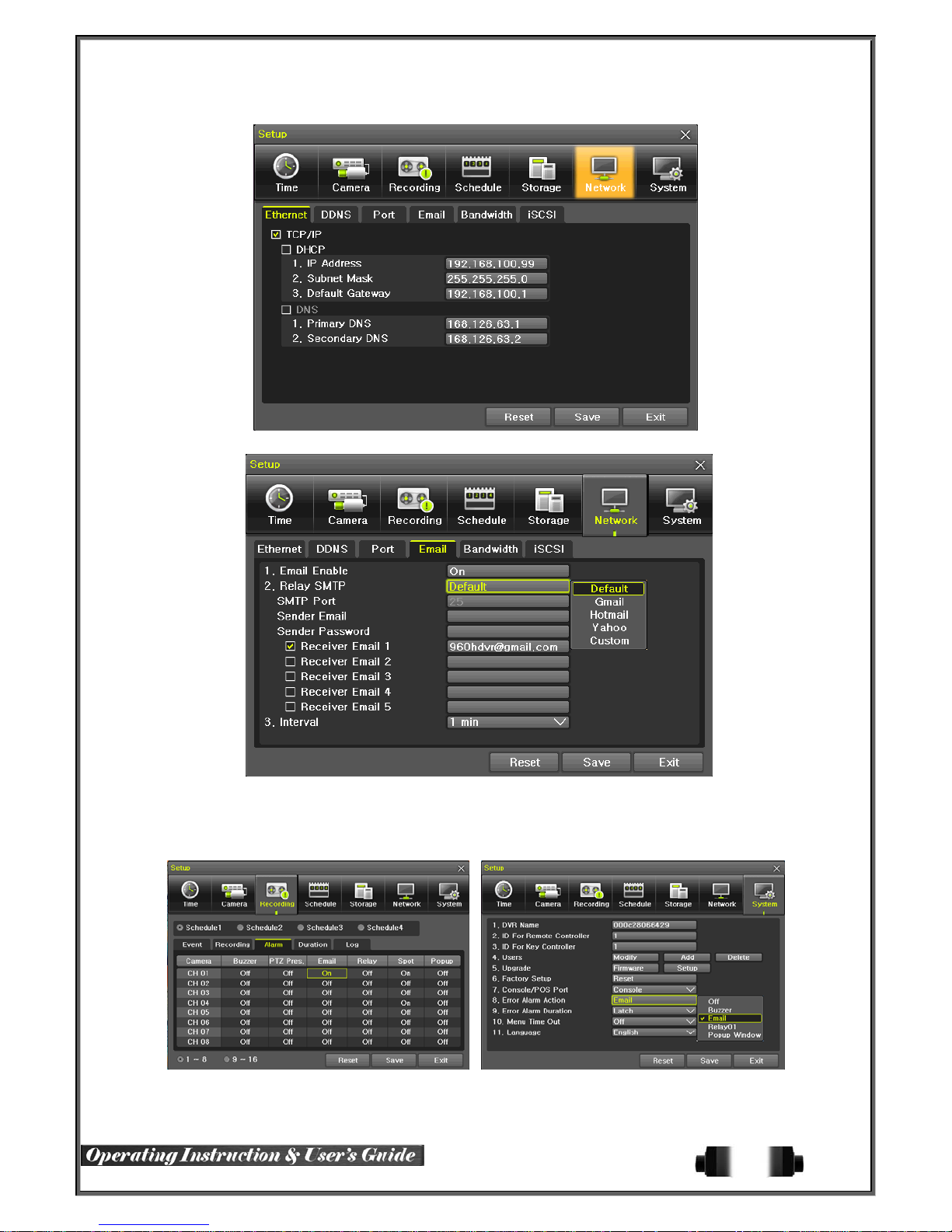
[Figure 6-55. Setup Network Ethernet Window]
This is to set automatic E-mail transmission service when an event occurs.
To use the e- mail function, {E-mail} in {Menu} {Setup} {System} {9. Alarm} or {E-mail} in {Menu}
{Setup} {Action} { Alarm} need to be configured.
[Figure 6-56. Setup Network E-Mail Window1]
[Figure 6-57. Setup Network E-Mail Window2]
64
Page 66

② Relay SMTP is set on ‘Gmail’ as default, but when ‘Default’ (in menu tab) is selected, this will changed
to dvr@cctvuser .com.
③ Receiver Email can be set up to 5 users (emails).
④ Email Interval settings are as follows [5 sec / 1 min / 3 min / 5 min /10 min].
6-6-5 Bandwidth
Move to {Menu} {Setup} {Network} {Bandwidth}.
This sets up the limit of the bandwidth to be used when bringing the live image, adjust resolution/quality and
transmitting the data by using the network.
Image Resolution CIF / D1 / 960H
Image Quality
Bandwidth Limit
Transmission
Codec
6-6-6 iSCSI
iSCSI
(Internet Small Computer System Interface) is a storage expansion function using the internet
(Ethernet) as extra storage base..
① Set to ‘Enable’.
② In put the IP Address & Port Number of the iSCSI, if ‘CHAP’ is available, input the ‘Account’ & ‘Password’
details.
③ When the ‘Session State’ shows ‘Active’, this is the normative state. When there is an ‘Error’, the
message ‘Check Network’ or ‘Log in Fail’ will be shown. Please check the ‘Network Settings and/or
Environment as well as the iSCSI settings state.
Adjust quality of the image, as the value increases, the
compression rate gets higher and image quality gets low.
However the transmiss ion rate gets higher.
You can set the network bandwidth between 40 ~ 4000kbps.
As the value increases, the network transmission speed gets
faster.
Select Off if you do not wish to limit the netwo rk bandw idth.
JPEC / H.264
[Figure 6-58. Set up iSCSI Window1]
65
Page 67

[Figure 6-59. Set up iSCSI Window2]
④ {Storage} -> {iSCSI} Tab, the registered iSCSI Storage will be displaced, and can be used for ‘
Recording’ purposes only.
⑤ When the ‘Status’ is shown as ‘Unusable’, this means that another DVR is currently using the
storage. The DVR’s Mac Address will be shown in ‘DVR Addr’.
※ Please note that ‘speeds’ will vary on the ‘net work environmen t’.
※ Network of over 100Mbps is highly r ecommended.
※ Only 1 ‘iSCSI Target’ is supported
※ Within the ‘iSCSI Target’, many Lun(HDD) can be registered, but when in use, 1 DVR
will use 1 Lun(HDD) at a time.
6-7 System
[Figure 6-60. System Setup Window]
66
Page 68

1. DVR Name Used to name the DVR device.
2. ID For Remote Controller Used to name the remote controller f or running the system.
3. ID For Key Controller Unique system controlle r numb er set ti ng.
4. User Registration Used to register, add, or delete users.
5. Admin. Password Used to set the password of the Local System Administrator.
6. Upgrade Upgrades the system firmware/system setu p
7. Factory Setup
8. Console / POS Port POS or Console Port Setting
9. Alarm Set the alarm On/Off and alarm format.
10. Alarm Duration Set the alarm time by continuous/5/10/15/User setting
11. Menu Time Out
12. Language System OSD language setting
Initialize Setup.(Factory default value, except for the network
value)
Used to set the time for exiting the System Setup menu
automatically and displaying the real-time monitoring screen.
6-7-1 DVR Name
. The initial value is the Mac address. (It supports up to 20 letters for the system name.))
6-7-2 ID for Remote Controller
When multiple devices are used, set the remote controller ID to identify input signals from the remote controller.
Only the system that DVR ID an d remote controller ID match can receive input signals from
the remote controller as shown below.
① Move to {Menu} {Setup} {System} {2. Remote Controller ID}.
② In the selection window, enter ID by using the arrow keys and the Select button (the number 0~99
is available for ID.)
If you forget the DVR ID, set the remote controller ID to 999 to start the DVR. Note, however,
that the DVR ID should be the same as the remote controller ID.
※ To configure Remote Controller ID (Example: ID setting as 3)
1) Press {ID} button on the remote controller.
2) Press the {0} key and {3} key.
3) Press {ID} button again.
4) Remote Controller ID is set as 3.
6-7-3 ID For Keyboard Controller
③ Move to {Menu} {Setup} {System} {3. ID for Key Controller.
④ In the selection window, enter ID by using the arrow keys and the Select button (number 1~255 is
available for ID.)
67
Page 69
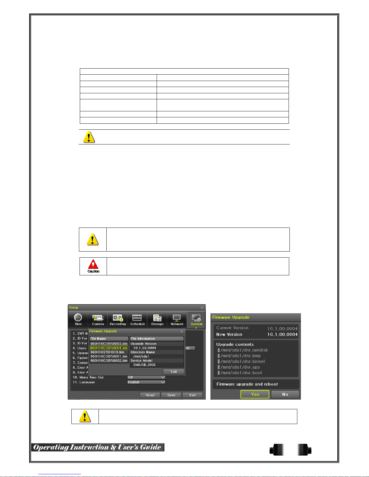
6-7-4 User Registration
※ Add, edit, or delete the users who will opera te the system and give authorities to users as shown below.
System Access Authorization
Network Live View the real-time images upon network access.
Playback View the recorded images.
Copy (download) Copy and downlo ad files.
PTZ camera PTZ camera control
Setup
Network Upgrade Remote network upgrade
Covert channel monitoring View the covert channel in the network.
Up to 15 users can be registered. Letters for ID and Password can be entered up
to 30.
6-7-5 Admin. Password
Recording, schedule, system, storage, Time, PTZ,
network, Screen setup
Setup the Administrator Password. The password can hold up to five digits.
6-7-6 Upgrade
The firmware and menu setting of the pr oduct can be easily upgraded through the use of the external storage
devices or portable storage devices with USB 2.0 port.
※
Find and copy the upgrade file to the highest folder in the external storage device or portable
storage device supporting USB 2.0
Connect the storage device with an upgrade file stored to USB 2.0 port at Right front panel.
※
1) After copying the upgrade file, be advised to get rid of the USB device with
safety removal mode from PC.
2) If the USB device is disconnected from the USB port while the upgrade file
is being copied, the DVR system may not automat ically detect the file.
Removing USB during the upgrade in progress may cause damage on the
system.
The system starts over when the upgrade is completed.
.
(2) Firmware Upgrade
① Select {Firmware} and the upgrade file list stored in the selected device and simple version info of
the selected file are then displayed. Select a file and Firmware Upgrade window appears.
[Figure 6-61. Firmware Upgrade Progressi ng Wi ndow]
※ Downgrading to a previous version is not supported.
※ The upgrade information window will th en appear within 15 seconds.
68
Page 70
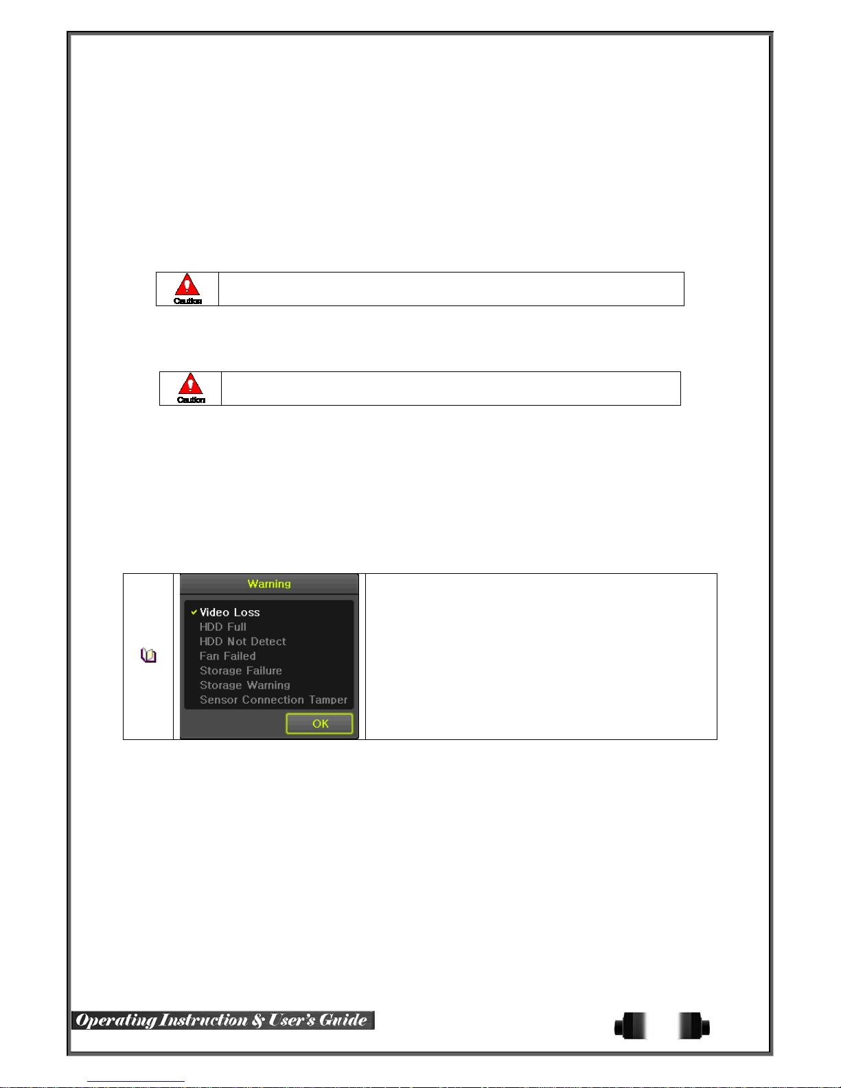
② Read the information and select {Yes} to start the upgrade gradually. Select {No} to return to the {
System} mode.
③ After the upgrade is completed, the system reboots.
④ Move to {Menu} {Miscellaneous} {DVR Information} {3. Software Version} to check the
version.
(3) Setup Upgrade
① Select {Setup} and the upgrade file list stored in the selected device and simple version info of
the selected file are then displayed.
② Select a file and then the upgrade starts immediately.
Select a file and then the upgrade starts immediately. All setting values of the
current menu will be changed to the upgrade setting va lu es.
6-7-7 Factory Default
① Move to {Menu} {Setup} {System} {7. Factory Setup}.
② Select {Yes} when Initialization (Yes/No) Window appears.
Note that all setting data will be initialized.
※ All values go back to Fac tory Default Value.
6-7-8Console / POS Port
① Move to {Menu} {Setup} {System} {8 Console / POS Port}.
② On the selection window, select the device by using the arrow keys and the Select button.
6-7-9 Alarm
Alarm is to notify system incidents [Video Signal loss/ HDD full/ FAN fail/ HDD fail/ HDD warning] through
[Buzzer/ E-mail/ Relay01/ System check].
Select each [Off/Buzzer/E-mail/Relay01/Popup Window] by ticking.
※ Popup Window
Setup at {Menu} {Setup} {System} {9. Alarm}.
Popup Window is to pop up the system check window in the
monitoring screen as shown. it indicates [Video Signal loss/ HDD
full/ HDD Not Detect / FAN fail/ Storage Fail/ Storage Warning /
Sensor Connection Tamper].
6-7-10 Alarm Duration
① It sets the duration of the alarm triggered by the recording and system event.
② Move to {Menu} {Setup} {System} {10. Alarm Duration}.
③ In the selection window, set Alarm Duration by using the arrow keys and the Select button.
6-7-11 Menu Time Out
If no input is made in the Syste m Setup menu from the front buttons , remote controller and mouse, the system
automatically shifts to the real-time monitoring mode.
① Move to {Menu} {Setup} {System} {11. Menu time Out}.
② In the selection window, select the time zone you want to set by using the arrow keys and the
select button.
69
Page 71
The Automatic Menu Exit is not used.
Off
1/2/3 MIN
User Setting
③ Selecting the User Setting causes the input window to appear.
④ Enter the time by using the numeric buttons or the arrow keys and the Select button.
6-7-12 Language
This feature is used to select the language for t he On Screen Displa y (OSD) menu of the s ystem. 18 languages
are supported.
※ The user can exit the menu by pressing the [ESC] button in the System
menu.
If there is no input from the front button, remote controller, or mouse, the
system will shift to the real-time monitoring mode.
The user can enter the time directly.
※ The time can be set to 1 ~ 60 minutes.
70
Page 72
A/P/P/E/N/D/I/X
Recommended PTZ Camera Protocol
NO
1 A.D.
2 CHOU COHU3925 COHU
3 Dongyang Dongyang
4 DYNACOLOR DSCP DSCP
5 EYE VIEW EYE VIEW EYE VIEW
6 FINE SYSTEM CRR-1600i/s CRR-1600i/s
7 GE GE GE_KARATEL
8 GSP GSP CYBERSCAN_1
9 HITRON FASTRAX2 FASTRAX2
10 HONEYWELL SCANDOME2 HSDN-251
11 LG LG
12 MIKAMI MIKAMI MIKAMI
13 ORIENTAL ORX-1000 ORX-1000
14 PANASONIC WVCS854 WVCS854
15 PELCO PELCO
16 PHILIPS PHILIPS PHILIPS
17 PROLINE PROLINE PROLINE_UK
18 RIFATRON RIFATRON-1 RIFATRON
19 SAMSUNG TECHWIN SAMSUNG
20 SUNJIN SUNJIN SUNJIN
21 VICON VICON VICON
22 YOKO YOKO YOKO
Vendor Model Protocol
APPENDIX
ULTRA_7
ULTRA_8
SENSORMATIC
DRX-500
DY-255
LG_MULTIX,
LG_OLD
PELCO – D
PELCO - P
SPD-1600
SCC641
71
Page 73

http://www.rugged-cctv.com/
866-301-2288 Toll Free
866-283-6003 Tech-Support
903-498-3240 Local
903-498-8989 Fax
72
 Loading...