

Page 1
Copyright © 2015 Ruckus Wireless, Inc.
Published 7 July 2015, Part Number 800-70607-001 Rev B
Page 1 of 4
START HERE
ZoneFlexTM P300 Wireless Bridge
Quick Setup Guide
This Quick Setup Guide provides information on how to configure the
Ruckus Wireless ZoneFlex P300 802.11ac point-to-point and point-tomultipoint outdoor wireless bridge on the network. The ZoneFlex P300 can
use its internal 5GHz antennas, or can optionally use a two-port customerordered external 5GHz antenna. After completing the steps described in
this Guide, you will be able to place the ZoneFlex P300 at your site. The
rest of this guide refers to the ZoneFlex P300 wireless bridge as the
ZoneFlex P300, root bridge, or non-root bridge.
The ZoneFlex P300 can be ordered either as an unconfigured single
ZoneFlex P300, or as a pre-configured matched pair of ZoneFlex P300s.
These ZoneFlex P300s are almost always installed in pairs, where one is
configured as a root bridge and the other as a non-root bridge.
The ZoneFlex P300 can be deployed as a root bridge connected to the
Ethernet backhaul, or can be deployed as a non-root bridge connected to
the root bridge via the wireless link. The ZoneFlex P300 can be equipped
with customer-purchased external 5GHz antennas to increase the root
bridge-to-non-root bridge connectivity range, or to increase the number of
non-root bridges that a root bridge can communicate with.
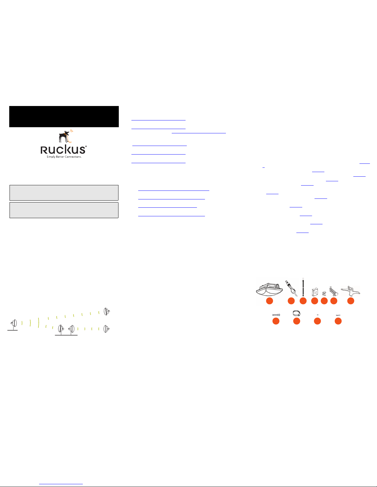
Figure 1. ZoneFlex P300s deployed as root bridge and non-root bridge
Note: When deployed in the root bridge--non-root bridge -to- root bridge-non-root bridge configuration, the two wireless links must use different
SSIDs.
This Guide in Other Languages
请从以下网站获得该指南的简体中文版
https://support.ruckuswireless.com
Vous trouverez la version française de ce guide à l'adresse suivante
https://support.ruckuswireless.com
こ のガ イ ド の 日本語版は https://support.ruckuswireless.com
でご覧くだ さい
이 가이드의 한국어 버전은 웹 사이트
(https://support.ruckuswireless.com) 에서 확인하시기 바랍니다
Veja a versão em português (Brasil) deste guia em
https://support.ruckuswireless.com
Puede ver la versión en español (América Latina) de esta guía en
https://support.ruckuswireless.com
Before You Begin
Before deploying Ruckus Wireless products, please check for the latest
software and the release documentation.
• User Guides and Release Notes are available at
http://support.ruckuswireless.com/documents
• Software Upgrades are available at
http://support.ruckuswireless.com/software
• Open Source information is available at
http://opensource.ruckuswireless.com
• Software License and Limited Warranty are available at
http://support.ruckuswireless.com/warranty
Safety Warnings
• WARNING! Only trained and qualified personnel should be allowed to
install, replace, or service this equipment. The professional installer is
responsible for the proper installation and configuration of this
ZoneFlex P300. The ZoneFlex P300 installation must comply with local
regulatory requirements, especially with those regulating operation
near military and/or weather radar systems.
• WARNING! Installation of this equipment must comply with local and
national electrical codes.
• WARNING! Ruckus Wireless strongly recommends that you wear eye
protection before mounting the ZoneFlex P300.
• WARNING! The Ruckus Wireless PoE injector (ordered separately) is
for indoor use only. Never mount the PoE injector outdoors with the
ZoneFlex P300.
• CAUTION: Make sure that you form a 80mm - 130mm (3”-5”) drip
loop in any cable that is attached to the ZoneFlex P300 or the building.
This will prevent water from running along the cable and entering the
ZoneFlex P300 or the building where the cable terminates.
• CAUTION: Be sure that grounding is available and that it meets local
and national electrical codes. For additional lightning protection, use
lightning rods and lightning arrestors.
• NOTE: Allowable external antenna types and antenna gains may be
limited by local regulatory requirements.
Package Contents
Before configuring or deploying your ZoneFlex P300, verify that all items
listed below are included in the package. If any item is damaged or
missing, notify your authorized Ruckus Wireless sales representative.
One or two ZoneFlex P300 kits, depending on ordered part:
• 901-P300-xx01, ZoneFlex P300, 802.11ac 5GHz point-to-point
wireless bridge, includes one ZoneFlex P300 kit
• 901-P300-xx02, ZoneFlex P300, 802.11ac 5GHz point-to-point
wireless bridge, pre-provisioned pair, includes two ZoneFlex P300 kits
where ‘xx’ is a country-specific code.
Each ZoneFlex P300 kit contains:
• One ZoneFlex P300, which includes a 12mm stainless steel M6x1
Phillips earth ground screw with split lock and flat washers (A in Figure
2)
• One M25 data cable gland (B in Figure 2)
• One green/yellow earth ground wire with ring terminal (C in Figure 2)
• One wall- or pole-mounting bracket (D in Figure 2)
• One U-joint bracket (E in Figure 2)
• One linkage bracket with two serrated external-tooth lock washers (F
in Figure 2)
• One ZoneFlex P300 bracket (G in Figure 2)
• Two sets 50mm stainless steel M8x1.25 hex bolt with split lock and
flat washers (H in Figure 2)
• Four SAE32-sized stainless steel clamps, 38.1mm to 63.5mm (1.5" to
2.5") inner diameter (I in Figure 2)
• Four sets stainless steel 8mm M4x0.7 pan head Phillips screws with
split lock and flat washers (J in Figure 2)
• Eight sets stainless steel 0.5-inch x 0.250-28 hex bolt with split lock
and flat washers (K in Figure 2)
• Service Level Agreement/Limited Warranty Statement
• Regulatory Statement
• Declaration of Conformity, if required
• This Quick Setup Guide
• ZoneFlex P300 Wireless Bridge Mounting Guide
• N-Type Connector Sealing Instructions
NOTE: This kit includes extra bolts, nuts and washers. You may use the
extras wherever required.
Figure 2. ZoneFlex P300 field-installation kit contents
Note: This Quick Setup Guide is designed to work with the ZoneFlex
P300 Wireless Bridge Mounting Guide. Complete the procedures in
this document before continuing with the Mounting Guide.
Note: The minimum software revision for the ZoneFlex P300 is base
image 100.1.0.9 or later. FlexMaster requires firmware 9.12 and later
to manage the ZoneFlex P300.
non-root bridge
non-root bridge
root bridge
root bridge
non-root bridge
F G
H
EA
C
B
D
I
J K
Page 2
Copyright © 2015 Ruckus Wireless, Inc.
Published 7 July 2015, Part Number 800-70607-001 Rev B
Page 2 of 4
LEDs and Indications
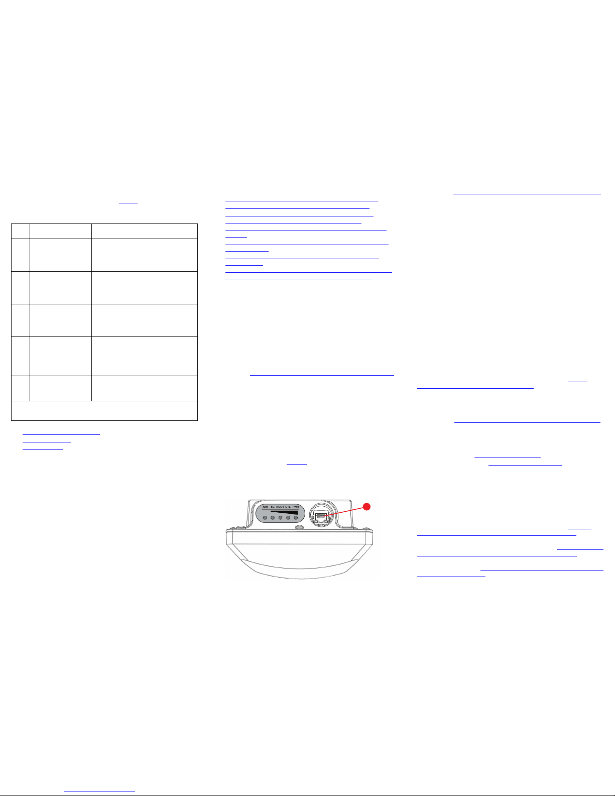
The ZoneFlex P300 has five LEDs visible on the outside of the chassis. The
LEDs have two different operating modes, and the LEDs can be manually
turned on and off by the operator. Refer to Table 1 for a description of
these LEDs and their operating modes.
Continue with the following:
• Configuring the ZoneFlex P300
• Physical Installation
• Troubleshooting
CONFIGURING THE ZONEFLEX P300
Continue with the following steps:
• Step 1: Collecting Setup Requirements, Hardware, and Tools
• Step 2: Connecting Your Computer to the ZoneFlex P300
• Step 3: Preparing Your Computer for ZoneFlex P300 Setup
• Step 4: Logging Into the ZoneFlex P300 Web Interface
• Step 5A: Manually Provisioning a ZoneFlex P300 Using the Web
Interface
• Step 5B: Manually Provisioning a Non-Root Bridge Using a Local
Configuration File
• Step 5C: Customizing the Wireless Settings for a Provisioned
ZoneFlex P300
• Step 6: Auto-Provisioning a Root Bridge and Non-Root Bridge Pair
• Step 7: Verifying Association Between the ZoneFlex P300s
Step 1: Collecting Setup Requirements, Hardware,
and Tools
• A computer with Ethernet adapter running Windows 7 or equivalent,
with Firefox or equivalent web browser. (Procedures for common
operating systems are similar.)
• Two Cat 5e (or better) Ethernet cables.
• A Ruckus Wireless 902-0184-xx00 or better PoE injector (sold
separately)
--OR-an 802.3af-compliant Power over Ethernet (PoE) switch or PoE
injector.
Continue with Step 2: Connecting Your Computer to the ZoneFlex P300.
Step 2: Connecting Your Computer to the ZoneFlex
P300
CAUTION: Do not attempt to access the Web interface of two ZoneFlex
P300s at the same time by connecting both to the same Layer 2 switch or
to the same broadcast domain on a live network. This causes a network
loop, which can disrupt your network.
1 After removing your ZoneFlex P300 from its package, place it next to
your computer.
2 Remove the cable gland from the bottom of the ZoneFlex P300.
3 Using an Ethernet cable, connect the 10/100/1000 Ethernet port on
the ZoneFlex P300 (A in Figure 3) to a PoE injector or switch for both
power and network connectivity.
4 If necessary, using another Ethernet cable, connect your computer’s
network port to a data/network port on the PoE injector or switch.
Figure 3. ZoneFlex P300 LEDs and Ethernet port
5 After bootup, verify that the PWR LED on the ZoneFlex P300 is a
steady green.
Continue with Step 3: Preparing Your Computer for ZoneFlex P300 Setup.
Step 3: Preparing Your Computer for ZoneFlex P300
Setup
NOTE: The following procedures assume that Windows 7 is the operating
system. Procedures for other operating systems are similar.
1 On your Windows 7 computer, configure your network adapter from
the Local Area Connection settings as follows:
• Start > Control Panel > Network and Sharing Center >
Change Adapter Settings
2 Edit the TCP/IPv4 address settings as follows:
• Local Area Connection > Properties > Internet Protocol
Version 4 (TCP/IPv4) > Properties
The Internet Protocol Version 4 (TCP/IPv4) Properties dialog box
appears.
IMPORTANT! Write down all of the currently active settings so you
can restore your computer to its current configuration when this procedure is completed.
3 Select Use the following IP address (if it is not already selected) and
then make the following entries:
• IP address: 192.168.2.22 (or any available address in the
192.168.2.x network, except 192.168.2.1 and 192.168.2.254,
which are the defaults used by the ZoneFlex P300s)
• Subnet mask: 255.255.255.0
Leave the DNS server and Default gateway fields empty.
4 Click OK to save your changes.
Your changes are put into effect immediately. Continue with Step 4:
Logging Into the ZoneFlex P300 Web Interface.
Step 4: Logging Into the ZoneFlex P300 Web
Interface
As specified in Step 3: Preparing Your Computer for ZoneFlex P300 Setup,
the computer should be connected to your ZoneFlex P300 through the
Ethernet port and powered on, ready for setup.
1 On your computer, open a Web browser window.
2 In the browser, enter a URL to connect to the ZoneFlex P300:
• Root bridge: https://192.168.2.1
• Non-root bridges: https://192.168.2.254
3 Press <Enter> to initiate the connection. When a security alert dialog
box appears, click OK/Yes to proceed.
4 When the Ruckus Wireless Admin login page appears, enter the fol-
lowing:
• Username: super
• Password: sp-admin
5 Click Login.
If the ZoneFlex P300 displays the Manual Provisioning Wizard page and
you do not have a local configuration file, then continue with Step 5A:
Manually Provisioning a ZoneFlex P300 Using the Web Interface.
If the ZoneFlex P300 displays the Manual Provisioning Wizard page and
you do have a local configuration file, then continue with Step 5B: Manually
Provisioning a Non-Root Bridge Using a Local Configuration File.
If a provisioned ZoneFlex P300 displays the Manual Provisioning Wizard
page, then continue with Step 5C: Customizing the Wireless Settings for a
Provisioned ZoneFlex P300.
Table 1. ZoneFlex P300 LED indications
LED Normal Mode Aiming Mode (all green)
PWR • Red = booting
• Green = normal
operation
Aiming Strength 4
• Solid: Min + 36 RSSI (RSSI >= 42)
• Blinking: Min + 32 RSSI
(42> RSSI >= 36)
CTL • Off = standalone
operation
• Other modes = to be
determined
Aiming Strength 3
• Solid: Min + 24 RSSI (36 > RSSI >= 30)
• Blinking: Min + 18 RSSI
(30 > RSSI >= 24)
ROOT • Off = non root bridge
• Solid green = root
bridge
Aiming Strength 2
• Solid: Min + 12 RSSI (24 > RSSI >= 18)
• Blinking: Min + 6 RSSI
(18 > RSSI >= 12)
5G • Off = radio down
• Solid green = radio
up & link up
• Flashing green =
radio up but no link
Aiming Strength 1
• Solid: RSSI >= Configured Minimum
(12 > RSSI >= 6)
• Blinking: RSSI < Configured minimum
(Default: 6 which is configurable)
AIM • Green = aiming
mode
• Off = normal mode
• Green = aiming mode (Note)
• Off = normal operation mode
Note: The P300 remains in aiming mode for 15 minutes after aiming is
started.
A
Page 3

Copyright © 2015 Ruckus Wireless, Inc.
Published 7 July 2015, Part Number 800-70607-001 Rev B
Page 3 of 4
Step 5A: Manually Provisioning a ZoneFlex P300
Using the Web Interface
Each root bridge can support up to 10 non-root bridges in a point-tomultipoint deployment. This step allows you to provision a ZoneFlex P300
as root bridge or a non-root bridge.
NOTE: When you are manually provisioning another ZoneFlex P300, you
may also need to assign a static IP address to avoid having multiple
ZoneFlex P300s with the same IP address (192.168.2.1 or 192.168.2.254),
unless the IP addresses are to be assigned using DHCP.
1 Log into the ZoneFlex P300’s Web interface as described in Step 4:
Logging Into the ZoneFlex P300 Web Interface.
2 If the ZoneFlex P300 is in the unprovisioned, factory-default state, then
the ZoneFlex P300 displays the Manual Provisioning Wizard.
3 In the Manual Provisioning Wizard, select Root AP for a root bridge, or
select Mesh AP for a non-root bridge.
4 Click Next. The Manual Provisioning Wizard displays the Tell us about
your WLAN configuration page.
NOTE: The following Channel Width, Country Code, SSID and Passphrase
entries must be the same for the root bridge and the non-root bridge.
5 In the Tell us about your WLAN configuration page, enter the following:
• Channel Width -- 20 MHz, 40 MHZ, or 80 MHz (default).
• Country Code -- Select the country in which the ZoneFlex P300s
will be operating.
NOTE: If you purchased the AP in the United States, then this
value is fixed to United States at the factory and is not user configurable. If you purchased the AP outside the United States, then
verify that the value is set to your country or region. Selecting the
correct country code ensures that the AP uses only the radio
channels allowed in your country or region.
• SSID -- Enter a link-specific service set identifier.
• Passphrase -- Enter a link-specific passphrase.
• Import Configuration (non-root bridge only) -- Click Choose File
to import the configuration file which has been exported from an
existing root bridge. The configuration file was exported from a
root bridge as described in Step 5C: Customizing the Wireless
Settings for a Provisioned ZoneFlex P300.
6 Click Next. The Manual Provisioning Wizard displays the Your Setup
page.
7 In the Your Setup page, click Reboot. The ZoneFlex P300 saves your
configuration and reboots.
If you have an unmatched pair of ZoneFlex P300s, then continue with Step
6: Auto-Provisioning a Root Bridge and Non-Root Bridge Pair. If you want
to verify the association between ZoneFlex P300s, then continue with Step
7: Verifying Association Between the ZoneFlex P300s.
Step 5B: Manually Provisioning a Non-Root Bridge
Using a Local Configuration File
Each root bridge can support up to 10 non-root bridges in a point-tomultipoint deployment. For best performance use no more than four nonroot bridges. This step allows you to provision a ZoneFlex P300 as a nonroot bridge using a local provisioning file.
NOTE: When you are manually provisioning another ZoneFlex P300, you
may also need to assign a static IP address to avoid having multiple
ZoneFlex P300s with the same IP address (192.168.2.1 or 192.168.2.254),
unless the IP addresses are to be assigned using DHCP.
1 Log into the ZoneFlex P300’s Web interface as described in Step 4:
Logging Into the ZoneFlex P300 Web Interface.
2 If the ZoneFlex P300 is in the unprovisioned, factory-default state, then
the ZoneFlex P300 displays the Manual Provisioning Wizard.
3 In the Manual Provisioning Wizard, select Mesh AP for a non-root
bridge.
4 Click Next. The Manual Provisioning Wizard displays the Tell us about
your WLAN configuration page.
5 In the Tell us about your WLAN configuration page, select Import Con-
figuration / Choose File. Select the configuration which has been
exported from an existing root bridge using the procedure in Step 5C:
Customizing the Wireless Settings for a Provisioned ZoneFlex P300.
6 Click Next. The Manual Provisioning Wizard displays the Your Setup
page.
7 In the Your Setup page, click Reboot. The ZoneFlex P300 saves your
configuration and reboots.
If you have an unmatched pair of ZoneFlex P300s, then continue with Step
6: Auto-Provisioning a Root Bridge and Non-Root Bridge Pair. If you want
to verify the association between ZoneFlex P300s, then continue with Step
7: Verifying Association Between the ZoneFlex P300s.
Step 5C: Customizing the Wireless Settings for a
Provisioned ZoneFlex P300
This step allows you to change the Channel Width, Country Code, SSID
and Passphrase selections, as well as the Channel, root bridge or non-root
bridge mode, and other Advanced and Rate Limiting settings. This step
also allows you to deactivate the internal antenna and activate external
5GHz antennas. Finally, it allows you to export a root bridge configuration
file which can be manually imported into a non-root bridge.
1 Log into the ZoneFlex P300’s Web interface as described in Step 4:
Logging Into the ZoneFlex P300 Web Interface.
2 Navigate to Configuration > Wireless. The Configuration > Radio 5G
page appears.
If the ZoneFlex P300 displays the Manual Provisioning Wizard page,
then skip this step and continue with Step 5A: Manually Provisioning a
ZoneFlex P300 Using the Web Interface or Step 5B: Manually Provisioning a Non-Root Bridge Using a Local Configuration File.
3 In the Configuration > Radio 5G page, make any or all of the following
changes:
CAUTION: The Channel, Channel Width, Country Code, SSID and
Passphrase entries must be the same for the root bridge and all non-root
bridges in the same linked group of ZoneFlex P300s.
CAUTION: If you are changing the Country Code after the ZoneFlex P300s
have already been configured, then you must configure the non-root
bridges first and then the root bridge last to avoid losing connectivity.
• Radio Network -- This name can be changed.
• Channel -- This can remain as Auto (SmartSelect) or you can
manually select a channel for this linked group of ZoneFlex P300s.
• Available Channel -- If you selected Auto Channel, then you can
deselect channels that you do not want the link to use. If you
selected any other Channel, then you can select channels that the
link can also use.
• Channel Width -- Select 20 MHz, 40 MHz, or 80 MHz (default).
• Country Code -- Select the country in which the ZoneFlex P300s
will be operating.
• Advanced Settings -- Click Edit Advanced Settings. Refer to the
Outdoor AP User Guide for instructions.
• Rate Limit Settings -- Click Edit Rate Limit Settings. Refer to the
Outdoor AP User Guide for instructions.
• External Antenna -- Select Enabled to use an external 5GHz
antenna, or select Disabled to use the internal ZoneFlex P300
antenna.
• SSID -- Enter a link-specific service set identifier.
• Passphrase -- Enter a link-specific passphrase.
• Wireless Bridge Mode -- Select Root AP
= root bridge or Mesh
AP = non-root bridge to change the basic ZoneFlex P300
configuration.
• Export Configuration (root bridge only) -- STOP! If you have
made no changes after updating the settings, then click Export
Configuration to have the ZoneFlex P300 save the current
configuration to a local computer file. If you have made any
Table 2. Default ZoneFlex P300 Settings (for your reference)
Channel Auto
Channel Width 80 MHz
Country Code United States
Default Management IP
Address
192.168.2.1 root bridge, and
192.168.2.254 non-root bridge
Page 4

Copyright © 2015 Ruckus Wireless, Inc.
Published 7 July 2015, Part Number 800-70607-001 Rev B
Page 4 of 4
changes, then click Update Settings to have the ZoneFlex P300
save your current selections before clicking Export
Configuration.
4 Click Update Settings to have the ZoneFlex P300 save your current
selections.
5 Click Logout to exit the Web interface.
6 When the Ruckus Wireless Admin login page reappears, you can exit
your browser.
7 Disconnect the ZoneFlex P300 from the computer and from the power
source, and then restore your computer to its original network connection configuration.
NOTE: You can use a Ruckus Wireless controller for bulk ZoneFlex P300
provisioning and performing other commands. Refer to the controller
documents for instructions.
If you have an unmatched pair of ZoneFlex P300s, then continue with Step
6: Auto-Provisioning a Root Bridge and Non-Root Bridge Pair. If you want
to verify the association between ZoneFlex P300s, then continue with Step
7: Verifying Association Between the ZoneFlex P300s.
Step 6: Auto-Provisioning a Root Bridge and NonRoot Bridge Pair
If you want a matched pair of root and non-root bridges for a point-to-point
connection, then continue with this step. If you do not want a matched pair
of root and non-root bridges, or if your ZoneFlex P300s are already a
matched pair, skip this step and continue with Step 7: Verifying Association
Between the ZoneFlex P300s.
NOTE: Auto provisioning can only be performed on two ZoneFlex P300s. If
you will be using more than two, then you will need to manually provision
the third ZoneFlex P300 using Step 5A: Manually Provisioning a ZoneFlex
P300 Using the Web Interface or Step 5B: Manually Provisioning a NonRoot Bridge Using a Local Configuration File after you have matched a pair
of ZoneFlex P300s first.
NOTE: The resulting root bridge is assigned IP address 192.168.2.1, and
the resulting non-root bridge is assigned IP address 192.168.2.254. Both
of these IP addresses can be changed manually or by using DHCP after
reboot.
1 Power up both ZoneFlex P300s.
2 Use an Ethernet cable to connect the two ZoneFlex P300s. The auto-
provisioning process starts.
During the auto-provisioning process, the ROOT LEDs on the ZoneFlex P300s flash about once every two seconds until a root and a nonroot bridge are selected. The process automatically chooses the
ZoneFlex P300 with the lower MAC address as the root bridge, and
automatically chooses the ZoneFlex P300 with the higher MAC
address as the non-root bridge.
When the auto-provisioning process is completed, the root bridge’s
ROOT LED is solid green, and the non-root bridge’s ROOT LED is off.
3 Note which ZoneFlex P300 is root and which is the non-root bridge.
4 Disconnect the Ethernet cable between the two ZoneFlex P300s, and
then:
A. Log into each ZoneFlex P300’s Web interface as described in
Step 4: Logging Into the ZoneFlex P300 Web Interface.
B. Navigate to the Maintenance > Reboot/Reset page and reboot
each ZoneFlex P300.
Continue with Step 7: Verifying Association Between the ZoneFlex P300s.
Step 7: Verifying Association Between the ZoneFlex
P300s
After you have provisioned a root and non-root pair, verify that they
automatically associate with each other.
1 If not already done, power up both ZoneFlex P300s.
2 Verify that the PWR LEDs on both ZoneFlex P300s are steady green.
3 Log into each ZoneFlex P300’s Web interface as described in Step 4:
Logging Into the ZoneFlex P300 Web Interface.
4 Navigate to each Status > Wireless page.
5 Wait approximately one to two minutes.
6 When the two ZoneFlex P300s associate with each other, in the Con-
nected Devices section each Status > Wireless page, the ZoneFlex
P300 display changes from “No stations are currently associated with
this WLAN” to a visual indicator of the connected ZoneFlex P300 IP
address, MAC address, SSID, and other information. When this infor-
mation appears, you have verified that the two ZoneFlex P300s are
associated with each other. Continue with Physical Installation
.
7 If the ZoneFlex P300s fail to associate with each other after a few min-
utes, make sure that the Country Codes, SSIDs, and Passphrases are
set to the same values, and that the Channels are set to Auto (or to the
same channel, if set manually).
If these settings are the same, then use the ping, traceroute, show
ARP table, and show FDB table tools on the Administration > Diag-
nostics page to diagnose the problem.
Congratulations! You have configured your ZoneFlex P300 wireless
bridge(s). Continue with Physical Installation
.
PHYSICAL INSTALLATION
After you have completed the procedures in this guide, continue with the
ZoneFlex P300 Wireless Bridge Mounting Guide.
TROUBLESHOOTING
CAUTION: If required, you can reset the ZoneFlex P300 to its factory
default settings by pressing and holding the reset button located inside the
PoE IN port, on the side farther from the ZoneFlex P300 LEDs, for six
seconds. DO NOT DO THIS UNLESS SO INSTRUCTED. (Doing this resets
the ZoneFlex P300 IP address to 192.168.2.1.)
NOTE: After a reset, you can access the internal ZoneFlex P300 web
interface using https://192.168.2.1 for a root bridge or https://
192.168.2.254 for a non-root bridge). Your device must use any other
address from 192.168.2.2 through 192.168.2.253, with subnet mask
255.255.255.0. The username is super, and the password is sp-admin.
Refer to the ZoneFlex P300 Wireless Bridge User Guide for information on
configuring and operating the ZoneFlex P300. This document is available at
https://support.ruckuswireless.com
NOTE: After a ZoneFlex P300 is removed from its mounting, it may drip
some water from the channel surrounding the radome. As long as the
ZoneFlex P300 has been operating normally, this incidental water
collection and dripping is normal, and is not service-affecting.
Optional: In a default ZoneFlex P300 configuration, the ZoneFlex P300
uses a DHCP-assigned IP address.
If you anticipate logging into the ZoneFlex P300 regularly to perform
monitoring or maintenance once it is in place, then you may want to
consider switching from DHCP and instead assigning a static IP address
to the ZoneFlex P300.
A. On the Web interface menu, click Configuration > Internet.
B. Click the Static IP option.
C. Fill in the IP Address and Mask fields.
D. Click Update Settings to save your changes.
 Loading...