

Page 1

ZoneFlex Indoor Access Point
Release 104.0
User Guide
Part Number: 800-71241-001 Rev A
Published: 22 August 2016
www.ruckuswireless.com
Page 2

Copyright Notice and Proprietary
Information
Copyright 2016. Ruckus Wireless, Inc. All rights reserved.
No part of this documentation may be used, reproduced, transmitted, or translated, in
any form or by any means, electronic, mechanical, manual, optical, or otherwise, without
prior written permission of Ruckus Wireless, Inc. (“Ruckus”), or as expressly provided
by under license from Ruckus.
Destination Control Statement
Technical data contained in this publication may be subject to the export control laws
of the United States of America. Disclosure to nationals of other countries contrary to
United States law is prohibited. It is the reader’s responsibility to determine the applicable
regulations and to comply with them.
2
Disclaimer
THIS DOCUMENTATION AND ALL INFORMATION CONTAINED HEREIN (“MATERIAL”)
IS PROVIDED FOR GENERAL INFORMATION PURPOSES ONLY. RUCKUS AND ITS
LICENSORS MAKE NO WARRANTY OF ANY KIND, EXPRESS OR IMPLIED, WITH
REGARD TO THE MATERIAL, INCLUDING, BUT NOT LIMITED TO, THE IMPLIED
WARRANTIES OF MERCHANTABILITY, NON-INFRINGEMENT AND FITNESS FOR A
PARTICULAR PURPOSE, OR THAT THE MATERIAL IS ERROR-FREE, ACCURATE OR
RELIABLE. RUCKUS RESERVES THE RIGHT TO MAKE CHANGES OR UPDATES TO
THE MATERIAL AT ANY TIME.
Limitation of Liability
IN NO EVENT SHALL RUCKUS BE LIABLE FOR ANY DIRECT, INDIRECT, INCIDENTAL,
SPECIAL OR CONSEQUENTIAL DAMAGES, OR DAMAGES FOR LOSS OF PROFITS,
REVENUE, DATA OR USE, INCURRED BY YOU OR ANY THIRD PARTY, WHETHER
IN AN ACTION IN CONTRACT OR TORT, ARISING FROM YOUR ACCESS TO, OR USE
OF, THE MATERIAL.
Trademarks
Ruckus Wireless, Ruckus, the bark logo, BeamFlex, ChannelFly, Dynamic PSK,
FlexMaster, Simply Better Wireless, SmartCell, SmartMesh, SmartZone, Unleashed,
ZoneDirector and ZoneFlex are trademarks of Ruckus Wireless, Inc. in the United States
and other countries. All other product or company names may be trademarks of their
respective owners.
ZoneFlex Indoor Access Point Release 104.0 User Guide
2
Page 3

Contents
Copyright Notice and Proprietary Information.............................................................................2
1 Introduction
Overview of the Ruckus Wireless Access Point.....................................................................6
Unpacking the Ruckus Wireless AP......................................................................................6
Package Contents................................................................................................................6
Controller Discovery and Standalone Operation....................................................................7
Getting to Know the AP Features..........................................................................................8
ZoneFlex 7055 Wall Switch.............................................................................................9
ZoneFlex 7352..............................................................................................................17
ZoneFlex 7372..............................................................................................................21
ZoneFlex 7372-E...........................................................................................................25
ZoneFlex 7982..............................................................................................................28
ZoneFlex H500 Wall Switch...........................................................................................32
ZoneFlex H510 Wall Switch...........................................................................................38
ZoneFlex R300..............................................................................................................42
ZoneFlex R310..............................................................................................................45
ZoneFlex R500..............................................................................................................49
ZoneFlex R510..............................................................................................................53
ZoneFlex R600..............................................................................................................57
ZoneFlex R700..............................................................................................................61
ZoneFlex R710..............................................................................................................65
2 Installation
Before You Begin................................................................................................................72
Performing a Site Survey...............................................................................................72
Determining the Optimal Mounting Location and Orientation.........................................72
Step 1: Preconfiguring the AP.............................................................................................74
Configuring the AP for Management by a SmartZone Controller....................................75
Configuring the AP for Management by ZoneDirector....................................................75
Configuring the AP for Standalone Operation or for Management by FM.......................76
Step 2: Verifying AP Operation............................................................................................83
Connect the AP to the Network.....................................................................................83
Associate a Wireless Client with the AP.........................................................................83
Check the LEDs............................................................................................................84
Check the TR069 Status (FlexMaster Management Only)..............................................84
ZoneFlex Indoor Access Point Release 104.0 User Guide
3
Page 4

Disconnect the AP from the Network.............................................................................84
Step 3: Deploying the AP....................................................................................................85
1. Choosing a Location for the AP.................................................................................85
2. Connecting the AP to a Power Source and the Network...........................................85
Troubleshooting the Installation...........................................................................................86
3 Navigation
Navigating the Web Interface..............................................................................................88
When You Are Using a Dual-Band AP.................................................................................89
4 Configuration
Configuring the AP..............................................................................................................90
Configuring Device Settings...........................................................................................90
Configuring Internet Settings.........................................................................................92
Configuring Wireless Settings........................................................................................99
Configuring Ethernet Ports..........................................................................................116
Configuring Hotspot Service........................................................................................121
5 Administration
Viewing Current Device Settings.......................................................................................128
Viewing Current Internet Connection Settings...................................................................128
Viewing Current Local Subnet Settings.............................................................................129
Viewing Common Wireless Settings..................................................................................130
Viewing Associated Wireless Clients..................................................................................132
Changing the Administrative Login Settings......................................................................133
Enabling Other Management Access Options...................................................................134
Viewing FlexMaster Management Status...........................................................................138
Pointing the AP to FlexMaster...........................................................................................139
Working with Event Logs and Syslog Servers....................................................................140
Enabling Logging and Sending Event Logs to a Syslog Server....................................140
Sending a Copy of the Log File to Ruckus Wireless Support........................................141
Saving a Copy of the Current Log to Your Computer...................................................141
Upgrading the Firmware Image.........................................................................................142
Upgrading Manually via FTP or TFTP...........................................................................142
Upgrading Manually via the Web.................................................................................143
Upgrading Manually via Local File................................................................................143
Scheduling Automatic Upgrades.................................................................................143
Rebooting the AP..............................................................................................................144
Resetting the AP to Factory Defaults.................................................................................145
Running Diagnostics.........................................................................................................145
4
ZoneFlex Indoor Access Point Release 104.0 User Guide
Page 5

Where to Find More Information........................................................................................146
Appendix A: AP Support for Bluetooth Low Energy Devices
Appendix B: Configuring Link Aggregation (LACP) for AP Backhaul
ZoneFlex Indoor Access Point Release 104.0 User Guide
5
Page 6

6
Introduction
Overview of the Ruckus Wireless Access Point
Congratulations on your purchase of the Ruckus Wireless AP!
Ruckus Wireless APs are the industry's most easy to use, yet robust and feature-rich
Wi-Fi APs designed to bring power and simplicity together for large-scale indoor
deployments.
Your Ruckus Wireless AP uses BeamFlex, a patented antenna technology from Ruckus
Wireless that allows wireless signals to navigate around interference, extend wireless
signal range, and increase speeds and capacity for wireless networks. The BeamFlex
antenna system consists of an array of high-gain directional antenna elements that allow
Ruckus Wireless APs to find quality signal paths in a changing environment, and sustain
the baseline performance required for supporting data, audio and video applications.
Your Ruckus Wireless AP can be deployed in standalone mode with or without a
FlexMaster (FM) manager, or as part of the Ruckus Wireless Smart WLAN system, in
which it can be managed by a Ruckus Wireless ZoneDirector or SmartZone controller.
NOTE For more information on the Ruckus Wireless system (including Ruckus Wireless
controllers and FlexMaster server), BeamFlex, and other Ruckus Wireless technologies,
visit www.ruckuswireless.com.
1
Unpacking the Ruckus Wireless AP
The first step after you have purchased a Ruckus Wireless indoor AP is to unpack the
AP and check the package contents.
1. Open the AP package, and then carefully remove the contents.
2. Return all packing materials to the shipping box, and put the box away in a dry
location.
3. Verify that all items listed in Package Contents below are included in the package.
Check each item for damage. If any item is damaged or missing, notify your authorized
Ruckus Wireless sales representative.
Package Contents
A complete AP package contains all of the items listed below:
• Ruckus Wireless AP
• Software License Agreement/Product Warranty Statement
ZoneFlex Indoor Access Point Release 104.0 User Guide
6
Page 7
Introduction
Controller Discovery and Standalone Operation
• Declaration of Conformity, if required
• Quick Setup Guide
• (Ethernet cables, power adapters and mounting kits are optional accessories that
may or may not be included depending on the SKU purchased)
Controller Discovery and Standalone Operation
Ruckus Wireless ZoneFlex Access Points can operate in either standalone mode, be
managed by FlexMaster server, or be managed by any of the Ruckus controller products.
How Standalone APs Learn Controller Addresses
If your AP will be managed by a controller, you will need some way to ensure that the
AP can discover the controller on the network. There are several different ways to do
this, and the specific controller user documents contain more details on discovery for
that particular controller product family.
This section provides a brief overview of the options available for controller discovery.
Ruckus Cloud
ZoneFlex APs discover Ruckus Cloud controllers by querying the Ruckus Cloud AP
Registrar (ap-registrar.ruckuswireless.com) via HTTPS to learn the Ruckus Cloud address.
APs will search for a Ruckus Cloud controller more frequently after initial boot up, and
less frequently after the first 14 days.
Standalone APs will query the Registrar with the following frequency:
Table 1: How often APs query the Registrar to learn Ruckus Cloud controller addresses
AP UptimeQuery Frequency
< 1 hour15 seconds
1 hours ~ 48 hours5 minutes
2 days ~ 14 days1 hour
14 days ~ forever12 hours
SmartZone
APs discover SmartZone controllers using any of the following methods:
• mDNS discovery on local IP subnet
• DHCP Option 43 sub-option 6
• DHCPv6 Option 17 sub-option 6
• DHCPv6 Option 52
ZoneFlex Indoor Access Point Release 104.0 User Guide
7
Page 8

Introduction
Getting to Know the AP Features
• DNS entry named "ruckuscontroller.<local domain>"
• AP CLI command "set scg ip"
ZoneDirector
APs discover ZoneDirector controllers using any of the following methods:
• IP subnet broadcast
• DHCP Option 43 sub-option 3
• DHCPv6 Option 17 sub-option 3
• DHCPv6 Option 52
• DNS entry named "zonedirector.<local domain>"
• AP CLI command "set director ip"
Getting to Know the AP Features
This section identifies the physical features of each Ruckus Wireless AP model that is
discussed in this guide. Before you begin the installation process, Ruckus Wireless
recommends that you become familiar with these features.
NOTE This User Guide does not include information on Ruckus Wireless Outdoor APs
or the ZoneFlex 7731 or P300 Wireless Bridge products. For information on those
ZoneFlex AP models, along with Ruckus Wireless ZoneDirector and SmartZone
controllers, FlexMaster, and other product lines, refer to their respective user
documentation available from support.ruckuswireless.com.
This release supports the following ZoneFlex indoor AP models:
• ZoneFlex 7055 Wall Switch on page 9
• ZoneFlex 7352 on page 17
• ZoneFlex 7372 on page 21
• ZoneFlex 7372-E on page 25
• ZoneFlex 7982 on page 28
• ZoneFlex H500 Wall Switch on page 32
• ZoneFlex H510 Wall Switch on page 38
• ZoneFlex R300 on page 42
• ZoneFlex R310 on page 45
• ZoneFlex R500 on page 49
• ZoneFlex R510 on page 53
• ZoneFlex R600 on page 57
• ZoneFlex R700 on page 61
• ZoneFlex R710 on page 65
8
ZoneFlex Indoor Access Point Release 104.0 User Guide
Page 9
Getting to Know the AP Features
ZoneFlex 7055 Wall Switch
The ZoneFlex 7055 is a multiservice 802.11n dual-band concurrent two-stream
wired/wireless wall switch.
NOTE The 100.x AP base images support standalone mode and FlexMaster (FM)
WLAN manager operation. The SmartZone software-compatible images only support
Ruckus Wireless SCG, SZ and vSZ controllers. The ZD-compatible images only support
ZD controllers.
NOTE The 7055 requires a minimum of AP base image 100.0.0 and later to operate,
or SCG 1.0 and later, vSZ 2.5 and later, SmartZone software 3.2 and later, or ZD 9.6
and later to operate.
The 7055 is designed for installation in an electrical junction box. This section identifies
the physical features the 7055. Before you begin the installation process, Ruckus Wireless
recommends that you become familiar with these features.
Front View Features
Introduction
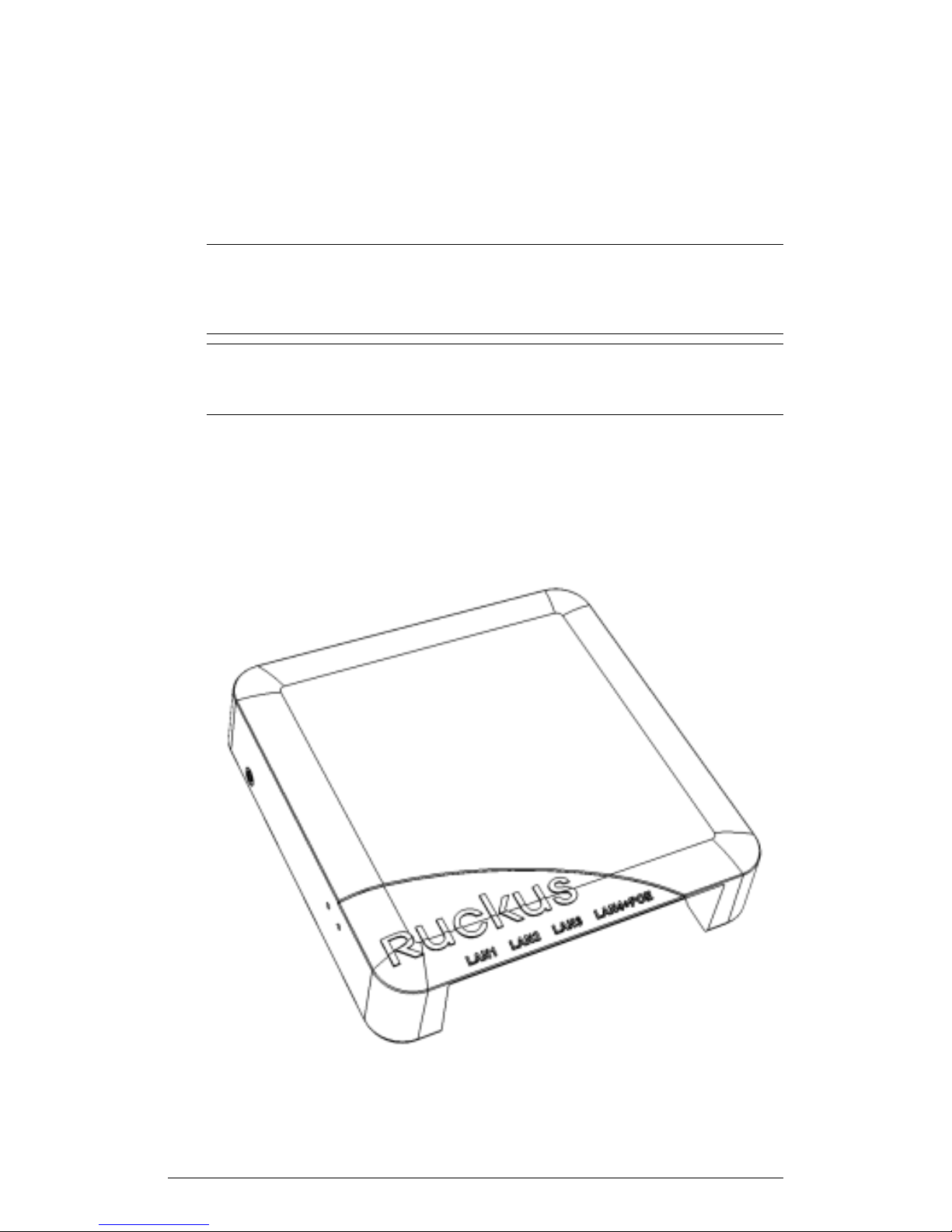
The front view of the 7055 includes four Ethernet Ports, a pass through port and a DC
in socket on the bottom front panel. Refer to the following table for more information.
ZoneFlex Indoor Access Point Release 104.0 User Guide
9
Page 10

Introduction
Getting to Know the AP Features
Figure 1: ZF7055 front view
Table 2: ZF7055 front view features
DescriptionNameNumber
Pass through port.Pass Through port1
Power Input2
Optional 48V DC power
input.
LAN1-LAN33
Three 10/100 RJ-45
Ethernet Ports.
LAN44
One 10/100 RJ-45 LAN port
with PoE out. Supports
802.3af PSE Class 0/2
(depending on power input).
Reset buttons5
Refer to “Reset Buttons”
below for details.
Rear Panel Features
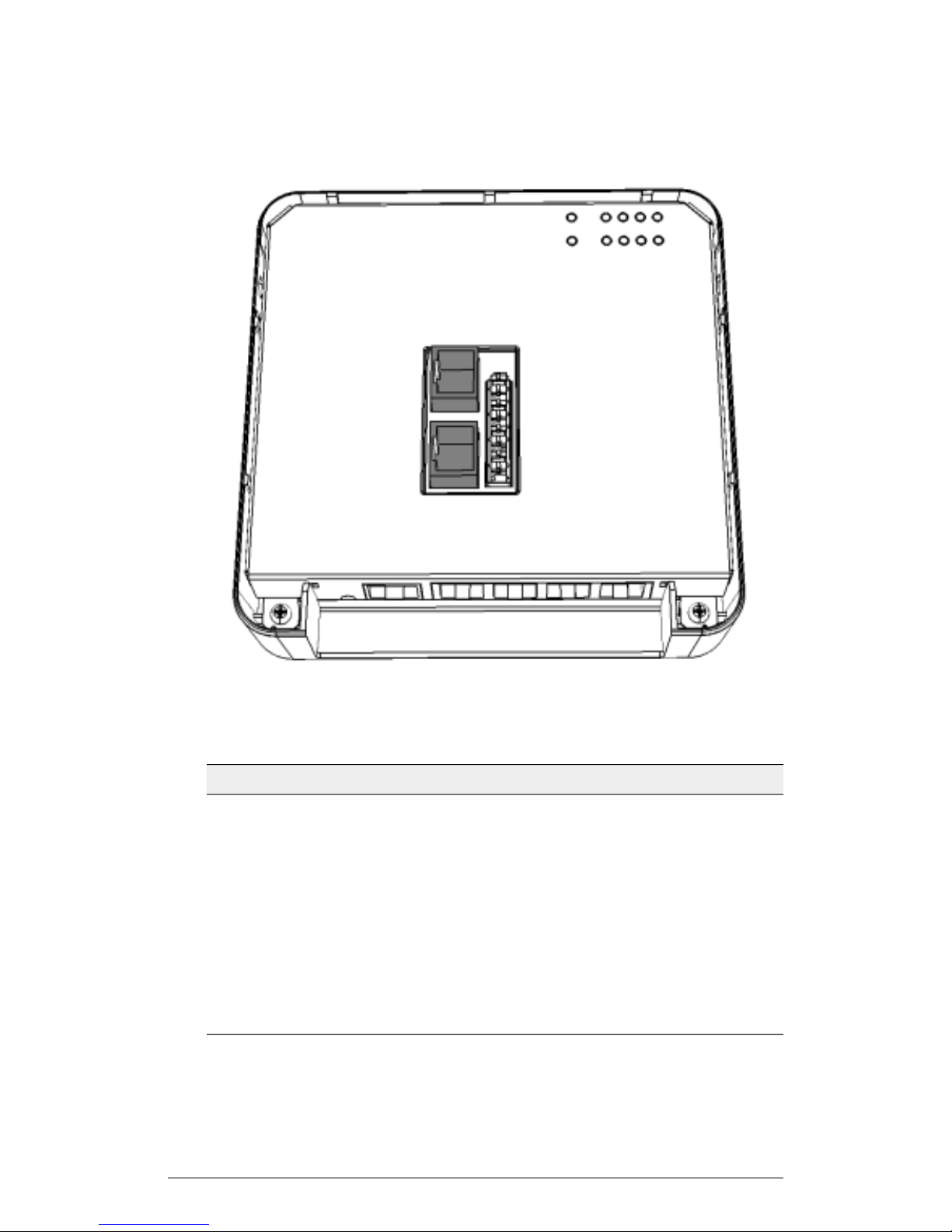
The following figure shows the rear panel of the 7055. For a description of each rear
panel element, refer to the table below.
10
ZoneFlex Indoor Access Point Release 104.0 User Guide
Page 11
Introduction
Getting to Know the AP Features
Figure 2: ZF 7055 rear panel
Table 3: ZF 7055 rear panel features
PoE In LAN/Uplink1
Pass Through Port3
LEDs4
DescriptionNameNumber
Uplink LAN port that
supports 802.3af and
802.3at Power over
Ethernet (PoE) input.
110 punchdown block.Punch down Block2
RJ-45 pass through port for
the pass through
connection.
See LEDs table for LED
descriptions and behaviors.
ZoneFlex Indoor Access Point Release 104.0 User Guide
11
Page 12
Introduction
Getting to Know the AP Features
LEDs
Refer to the table below for descriptions of LEDs and their behaviors. The LEDs are not
visible once the AP is installed.
Table 4: ZF 7055 LEDs
DefinitionLED
PWR
WAN
5G
• Off: Off
• Red: Bootup in process
• Flashing Green: No routable IP address
• Green: On
• Green: Link up.
• Flashing green: Activity.
• Off: Link down.
• Off: The WLAN service is down.
• Amber: The WLAN is up, but no clients
are associated and no downlink MAPs
are connected.
• Green: The WLAN is up and at least
one client is associated. No downlink
MAPs are connected.
• Slow flashing green (one flash every two
seconds): The WLAN is up and at least
one downlink MAP is connected. No
clients are associated.
• Fast flashing green (two flashes every
second): The WLAN is up, at least one
downlink MAP is connected, and at
least one client is associated.
2.4G
12
• Off: The WLAN service is down.
• Amber: The WLAN is up, but no clients
are associated and no downlink MAPs
are connected.
• Green: The WLAN is up and at least
one client is associated. No downlink
MAPs are connected.
ZoneFlex Indoor Access Point Release 104.0 User Guide
Page 13

Introduction
Getting to Know the AP Features
DefinitionLED
AIR
DIR
• Off: The AP is operating in standalone
mode or operating as a root AP (RAP)
or a non-mesh AP.
• Green: The AP is functioning as a Mesh
AP (MAP), and the wireless signal to its
uplink AP is good.
• Fast flashing green (two flashes every
second): The AP is functioning as a
Mesh AP (MAP), and the wireless signal
to its uplink AP is fair.
• Slow flashing green (one flash every two
seconds): Mesh networking is enabled,
but the AP is still searching for a mesh
uplink.
• Off: The AP is not being managed by a
Ruckus Wireless controller (standalone
mode).
• Green: The AP is being managed by a
Ruckus Wireless controller.
• Slow flashing green (one flash every two
seconds): The AP is being managed by
a controller, but is currently unable to
communicate with the controller.
• Fast flashing green (two flashes every
second): The AP is being managed by
a controller and is currently receiving
configuration settings (provisioning) or
an image update.
LAN1 - LAN4
Reset Buttons
Two reset buttons on the left side of the AP are used to reboot or factory reset the AP.
ZoneFlex Indoor Access Point Release 104.0 User Guide
• Green: Link up.
• Flashing green: Activity.
• Off: Link down.
13
Page 14

Introduction
Getting to Know the AP Features
Figure 3: Reset buttons
Press and hold the Soft Reset button for three seconds or more to reset the AP to
factory defaults. Press and release the Hard Reset button to restart the AP.
NOTE On the 7055, the Hard reset button restarts the AP, while the Soft reset button
reverts the AP to factory default settings.
7055 Physical Installation
This section describes the physical installation instructions for mounting the 7055 to an
electrical outlet box.
CAUTION! The AP and all interconnected equipment must be installed indoors within
the same building, including the PoE powered network connection as described by
Environment A of the 802.3af standard.
CAUTION! Ensure that you use a Cat5e or better Ethernet cable to supply PoE power
and LAN connectivity running to the outlet box where the AP will be installed.
14
ZoneFlex Indoor Access Point Release 104.0 User Guide
Page 15
Introduction
Getting to Know the AP Features
1. Prepare the electrical outlet box.
2. The 7055 can be mounted to a variety of commonly used electrical outlet box formats,
including US style outlet boxes conforming to NEMA-WD6, and EU style outlet boxes
conforming to BS 4662.
NOTE The 7055 comes with a bracket for a single 1-gang electrical outlet box. For
adjacent outlet boxes, use the optional Ruckus Wireless ZF7055 adjacent wall bracket
kit (part number 902-0111-000).
• Remove the outlet box cover from the outlet box, retaining the original box cover
screws.
• Align the mounting bracket with the outlet box so that the screw holes line up (the
bracket provides multiple holes for different outlet box designs), and
• Pull the Ethernet cable through the center of the mounting bracket.
• Affix the mounting bracket to the outlet box using the original outlet box cover
screws. If the original outlet box screw heads extend over 2mm from the bracket,
then use the enclosed low profile mounting screws instead.
• Run the required cables through the electrical outlet box allowing sufficient slack
for the cables to reach the not yet installed 7055.
3. Connect the cables.
• Connect an Ethernet cable providing PoE power and network connectivity to the
PoE In LAN / Uplink port using either a standard RJ45 connector or the 110
punch-down block (refer to Using the 110 Punch Down Block on page 16).
• If PoE power is not available, the AP can be powered using an optional DC power
adapter (Ruckus part No. 902-0170-XX10, sold separately)
• If required, connect the cable providing support for pass-through devices to the
Pass Through port.
NOTE The status LEDs are intentionally not visible once the 7055 is mounted.
Complete any verification or troubleshooting that requires visibility of the LEDs before
mounting.
ZoneFlex Indoor Access Point Release 104.0 User Guide
15
Page 16
Introduction
Getting to Know the AP Features
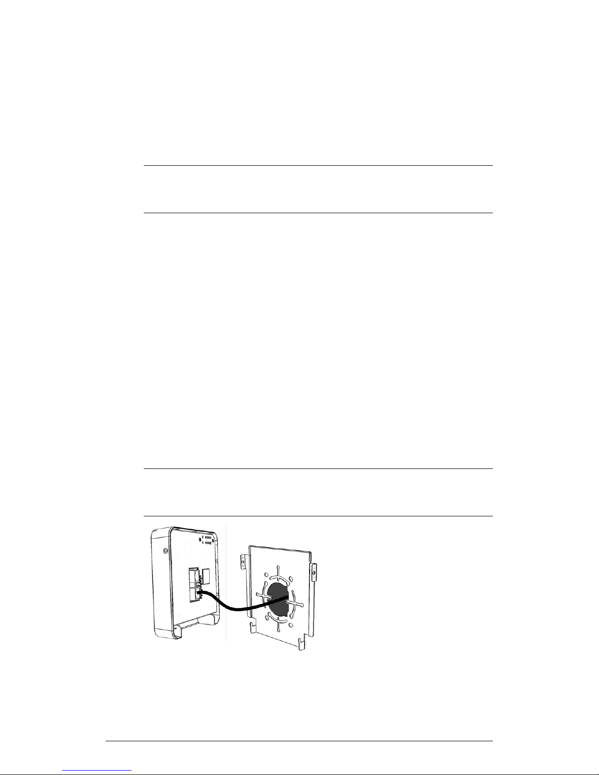
Figure 4: Attach 7055 AP cables before mounting to the bracket
4. Mount the AP to the bracket.
• Snap the AP onto the mounting bracket by hooking the two locking tabs on the
bottom of the bracket into the slots on the bottom of the AP. Then push the top
of the AP in toward the wall until it snaps in place.
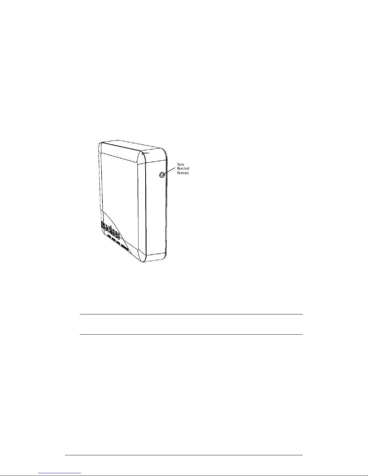
• Use the two Torx bracket screws provided to secure the AP to the mounting
bracket using a T10 Torx screwdriver.
Figure 5: Secure the 7055 AP to the bracket using Torx screws
Using the 110 Punch Down Block
The ZF 7055 provides a 110 punch down block in addition to the RJ-45 port on the rear
of the AP for power and network connectivity.
CAUTION! Do not connect both the Punch-down block and the Uplink port to a
network. Only one connection can be used at a time.
If you prefer to use the 110 Punch-down block connector rather than the RJ-45 connector
for power and network connectivity, refer to the following diagram for wiring details.
16
ZoneFlex Indoor Access Point Release 104.0 User Guide
Page 17
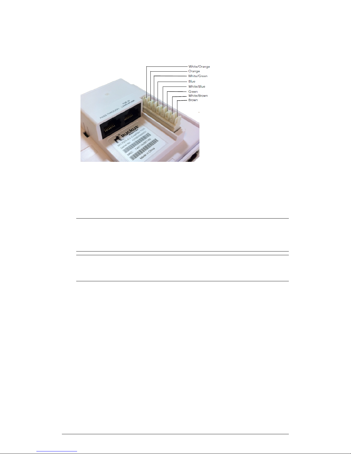
Figure 6: 7055 AP punch-down block wiring
Introduction
Getting to Know the AP Features
ZoneFlex 7352
The ZoneFlex 7352 is a best-performing, mobile-ready, two-stream single-band (2.4
GHz) 802.11n AP.
NOTE The 100.x AP base images support standalone mode and FlexMaster (FM)
WLAN manager operation. The SmartZone software-compatible images only support
Ruckus Wireless SCG, SZ and vSZ controllers The ZD-compatible images only support
ZD controllers.
NOTE The 7352 requires a minimum of AP base image 100.0.0 and later to operate,
or SCG 1.1.1 and later, vSZ 2.5 and later, SmartZone software 3.2 and later, or ZD 9.5.1
and later to operate.
The 7352 includes five LEDs on its front panel and buttons and connectors on its rear
panel.
Front Panel
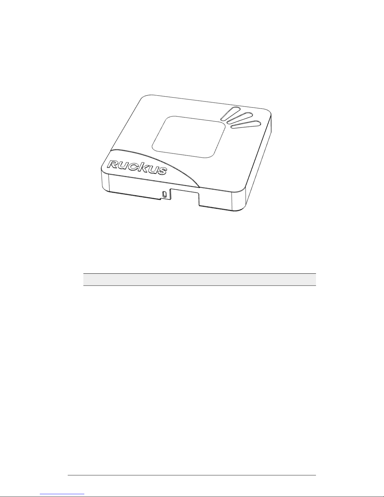
The following figure shows the top view of the 7352. For a description of each front panel
part, refer to the table below.
ZoneFlex Indoor Access Point Release 104.0 User Guide
17
Page 18
Introduction
Getting to Know the AP Features
Figure 7: 7352 top view
Table 5: 7352 front panel elements
PWR LED
DescriptionLED
• Off: Off.
• Red: Boot up in process.
• Flashing Green: No routable IP address
• Green: On.
Not used in this model.OPT LED
18
ZoneFlex Indoor Access Point Release 104.0 User Guide
Page 19

Introduction
Getting to Know the AP Features
DescriptionLED
DIR LED
WLAN LED
• Off: The AP is not being managed by a
Ruckus Wireless controller (standalone
mode).
• Green: The AP is being managed by a
Ruckus Wireless controller.
• Slow flashing green (one flash every two
seconds): The AP is being managed by
a controller, but is currently unable to
communicate with the controller.
• Fast flashing green (two flashes every
second): The AP is being managed by
a controller and is currently receiving
configuration settings (provisioning) or
an image update.
• Off: The WLAN service is down.
• Amber: The WLAN service is up and no
clients are associated (standalone), or
no wireless clients and no downlink
MAPs are connected (RAP).
• Green: The WLAN service is up and at
least one wireless client is associated.
If Mesh is enabled, no downlink MAPs
are connected.
• Fast flashing green: The WLAN service
is up, at least one client is associated,
and at least one Mesh downlink is
connected.
• Slow flashing green: At least one Mesh
downlink is connected, and no clients
are associated.
ZoneFlex Indoor Access Point Release 104.0 User Guide
19
Page 20
Introduction
Getting to Know the AP Features
DescriptionLED
AIR LED
• Off: The AP is operating in standalone
mode or operating as a root AP (RAP)
or a non-mesh AP.
• Green: The AP is functioning as a RAP
or MAP and the uplink signal is good.
• Slow flashing green (one flash every two
seconds): Mesh networking is enabled,
but the AP is still searching for a mesh
uplink.
• Fast flashing green (two flashes every
second): The AP is functioning as a
MAP and the wireless signal to its uplink
AP is fair.
Rear Panel
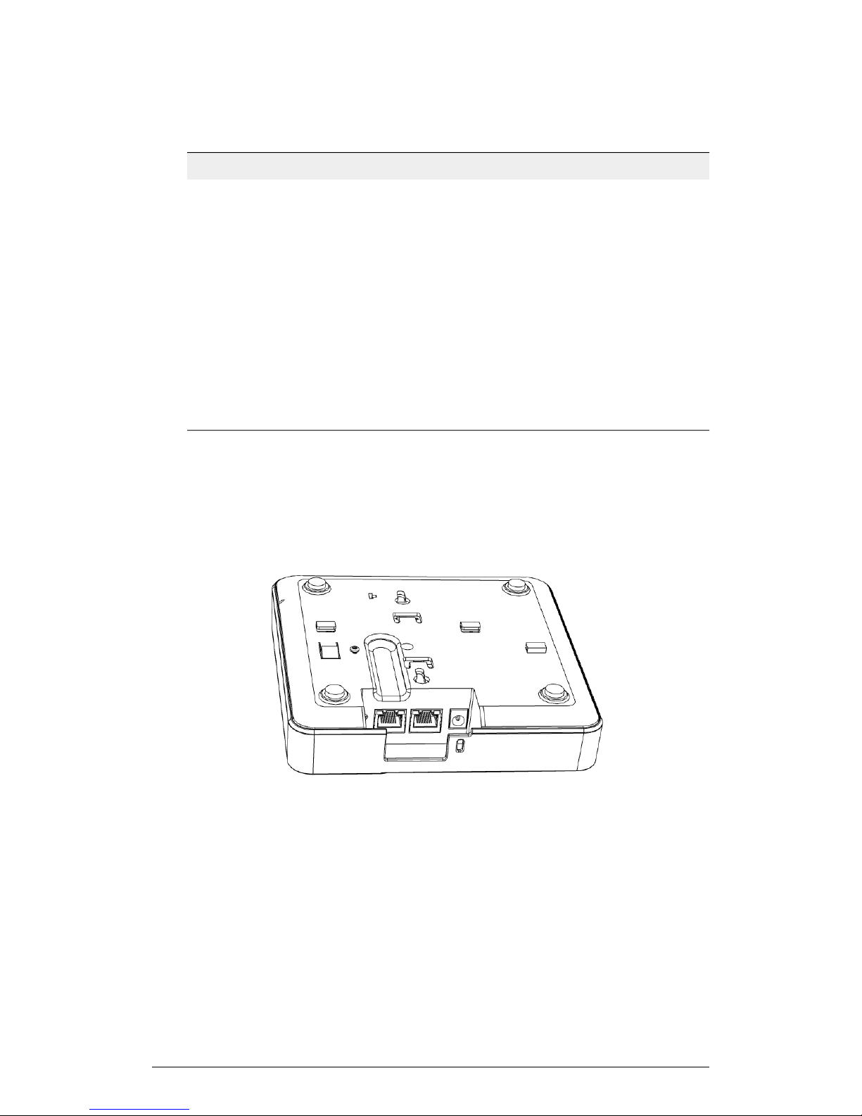
The following figure shows the rear panel of the 7352 (and 7372). For a description of
each rear panel part, refer to the table below.
20
ZoneFlex Indoor Access Point Release 104.0 User Guide
Page 21

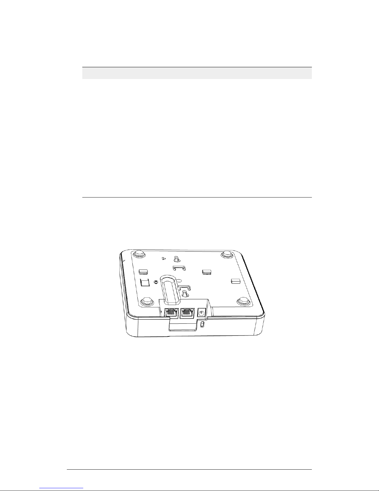
Figure 8: 7352/7372 rear panel
Table 6: 7352/7372 rear panel elements
Introduction
Getting to Know the AP Features
DescriptionItem Name
10/100/1000+PoE Port
Power
RST Button
One RJ-45 port for a 10/100/1000 PoE
(Power over Ethernet, 802.3af) connection.
One RJ-45 port for a 10/100 connection.10/100 Port
Connect the power adapter (12
VDC/1.25A) to this socket. Power can also
be supplied via the 10/100/1000 PoE port.
Pressing, and then quickly releasing this
internal button reboots the AP. Pressing
and holding it for six seconds resets the
AP to factory default settings.
CAUTION! Resetting the AP to factory
default settings erases all previously
configured settings.
ZoneFlex 7372
The ZoneFlex 7372 is a best-performing, concurrent dual-band, mobile-ready, two-stream
802.11n AP.
NOTE The 100.x AP base images support standalone mode and FlexMaster (FM)
WLAN manager operation. The SmartZone software-compatible images only support
SCG, SZ and vSZ controllers. The ZD-compatible images only support ZD controllers.
NOTE The 7372 requires a minimum of AP base image 100.0.0 and later to operate,
or SCG 1.1.1 and later, vSZ 2.5 and later, SmartZone software 3.2 and later, or ZD 9.5.1
and later to operate.
The 7372 includes five LEDs on its front panel and buttons and connectors on its rear
panel.
Front Panel
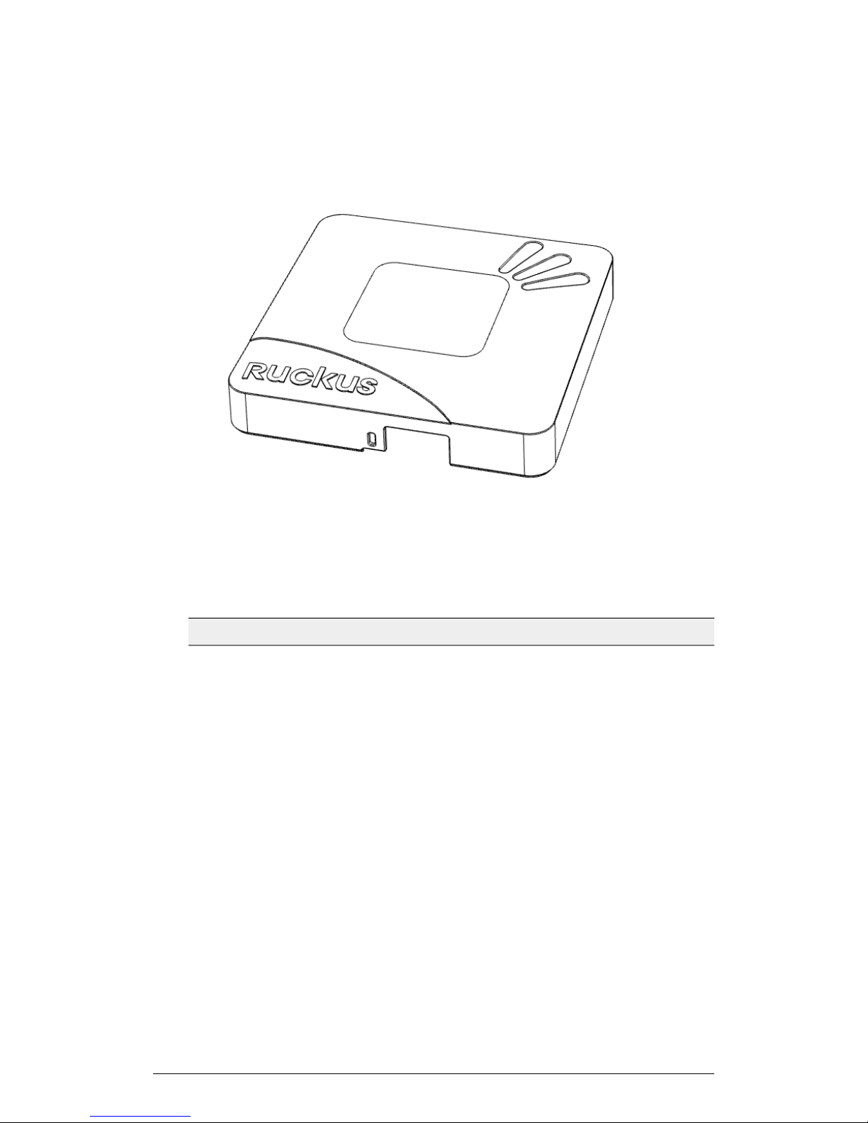
The following figure shows the top view of the 7372. For a description of each front panel
part, refer to the table below.
ZoneFlex Indoor Access Point Release 104.0 User Guide
21
Page 22
Introduction
Getting to Know the AP Features
Figure 9: 7372 top view
Table 7: 7372 front panel elements
Power LED
DescriptionLED
• Off: Off.
• Red: Boot up in process.
• Flashing Green: No routable IP address.
• Green: On.
22
ZoneFlex Indoor Access Point Release 104.0 User Guide
Page 23

Introduction
Getting to Know the AP Features
DescriptionLED
DIR LED
AIR LED
• Off: The AP is not being managed by a
Ruckus Wireless controller (standalone
mode).
• Green: The AP is being managed by a
Ruckus Wireless controller.
• Slow flashing green (one flash every two
seconds): The AP is being managed by
a controller, but is currently unable to
communicate with the controller.
• Fast flashing green (two flashes every
second): The AP is being managed by
a controller and is currently receiving
configuration settings (provisioning) or
an image update.
• Off: The AP is operating in standalone
mode or operating as a root AP (RAP)
or a non-mesh AP.
• Green: The AP is functioning as a Mesh
AP (MAP), and the wireless signal to its
uplink AP is good.
• Fast flashing green (two flashes every
second): The AP is functioning as a
Mesh AP (MAP), and the wireless signal
to its uplink AP is fair.
• Slow flashing green (one flash every two
seconds): Mesh networking is enabled,
but the AP is still searching for a mesh
uplink.
2.4GHz LED
ZoneFlex Indoor Access Point Release 104.0 User Guide
• Off: The WLAN service is down.
• Green: The WLAN is up and at least
one client is associated.
• Amber: The WLAN is up. No clients are
associated.
23
Page 24
Introduction
Getting to Know the AP Features
DescriptionLED
5GHz LED
• Off: The WLAN service is down.
• Amber: The WLAN is up, but no clients
or downlink MAPs are
associated/connected.
• Green: The WLAN is up and at least
one client is associated. No downlink
MAPs are connected.
• Green: The WLAN is up and at least
one client is associated. No downlink
MAPs are connected.
• Fast flashing green (two flashes every
second): The WLAN is up, at least one
downlink MAP is connected, and at
least one client is associated.
Rear Panel
The rear panel of the 7372 is the same as the 7352. See ZoneFlex 7352 on page 17.
24
ZoneFlex Indoor Access Point Release 104.0 User Guide
Page 25
Getting to Know the AP Features
Figure 10: 7372 rear panel
ZoneFlex 7372-E
The ZoneFlex 7372-E is a best-performing, concurrent dual-band, mobile-ready,
two-stream 802.11n AP, with two RP-SMA connectors used to support dual-band
2.4GHz and 5GHz external antennas.
NOTE The 100.x AP base images support standalone mode and FlexMaster (FM)
WLAN manager operation. The SmartZone software-compatible images only support
SCG, SZ and vSZ controllers. The ZD-compatible images only support ZD controllers.
NOTE The 7372-E requires a minimum of AP base image 100.0.0 and later to operate,
or SCG 2.1 and later, vSZ 2.5 and later, SmartZone software 3.2 and later, or ZD 9.6
and later to operate.
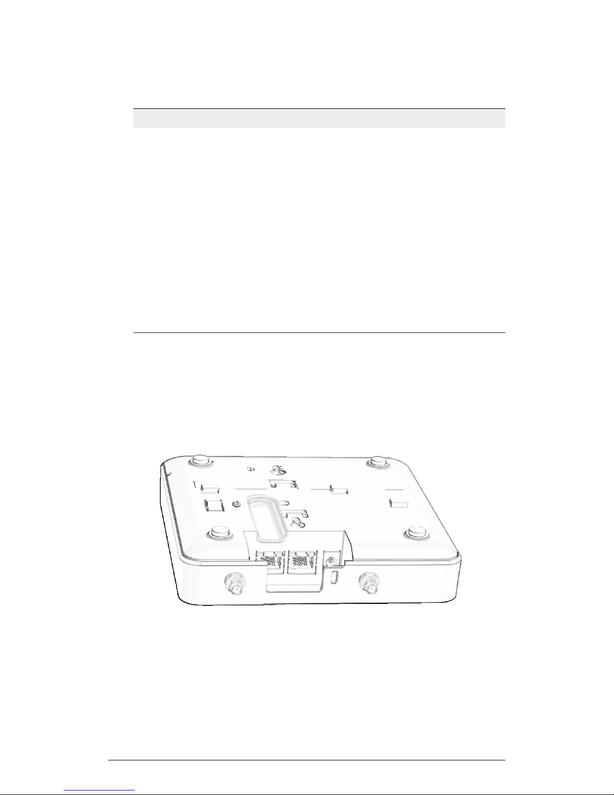
The 7372-E includes five LEDs on its front panel and buttons and connectors on its rear
panel.
Introduction
Front Panel
The following figure shows the top view of the 7372-E. For a description of each front
panel part, refer to the table below.
ZoneFlex Indoor Access Point Release 104.0 User Guide
25
Page 26

Introduction
Getting to Know the AP Features
Figure 11: 7372-E top view
Table 8: 7372-E front panel elements
DescriptionLED
Power LED
DIR LED
AIR LED
• Off: Off.
• Red: Boot up in process.
• Flashing Green: No routable IP address
• Green: On.
• Off: The AP is not being managed by a
Ruckus Wireless controller (standalone
mode).
• Green: The AP is being managed by a
Ruckus Wireless controller.
• Slow flashing green (one flash every two
seconds): The AP is being managed by
a controller, but is currently unable to
communicate with the controller.
• Fast flashing green (two flashes every
second): The AP is being managed by
a controller and is currently receiving
configuration settings (provisioning) or
an image update.
• Off: The AP is operating in standalone
mode or operating as a root AP (RAP)
or a non-mesh AP.
• Green: The AP is functioning as a Mesh
AP (MAP), and the wireless signal to its
uplink AP is good.
• Fast flashing green (two flashes every
second): The AP is functioning as a
Mesh AP (MAP), and the wireless signal
to its uplink AP is fair.
• Slow flashing green (one flash every two
seconds): Mesh networking is enabled,
but the AP is still searching for a mesh
uplink.
2.4GHz LED
26
• Off: The WLAN service is down.
• Green: The WLAN is up and at least
one client is associated.
• Amber: The WLAN is up. No clients are
associated.
ZoneFlex Indoor Access Point Release 104.0 User Guide
Page 27
Introduction
Getting to Know the AP Features
DescriptionLED
5GHz LED
• Off: The WLAN service is down.
• Amber: The WLAN is up, but no clients
or downlink MAPs are
associated/connected.
• Green: The WLAN is up and at least
one client is associated. No downlink
MAPs are connected.
• Slow flashing green (one flash every two
seconds): The WLAN is up and at least
one downlink MAP is connected. No
clients are associated.
• Fast flashing green (two flashes every
second): The WLAN is up, at least one
downlink MAP is connected, and at
least one client is associated.
Rear Panel
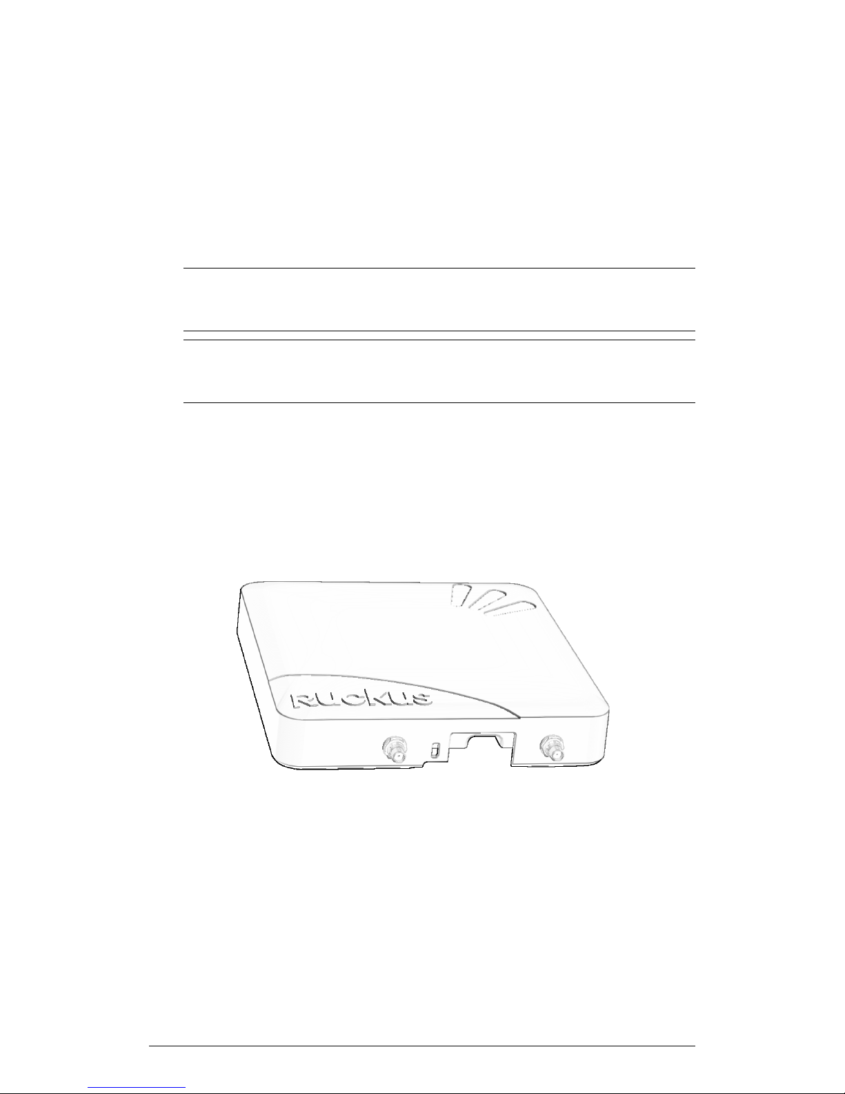
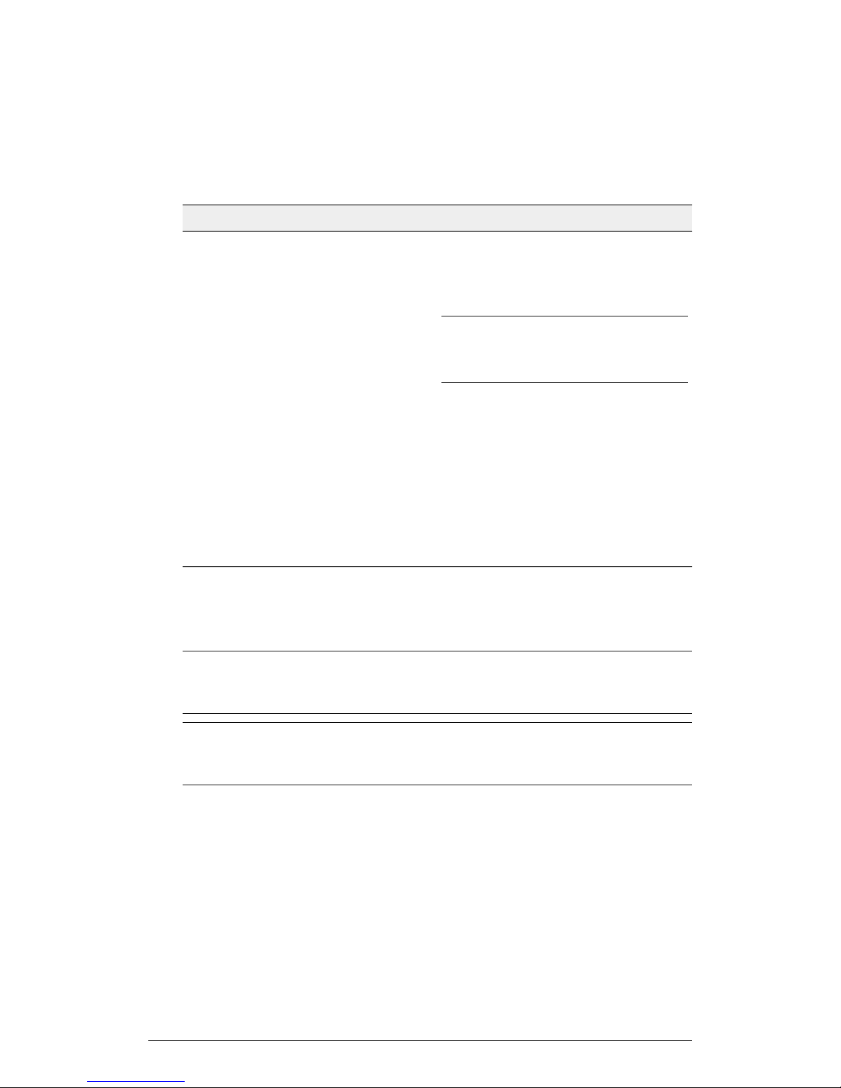
The flollowing figure shows the rear panel of the 7372-E. For a description of each rear
panel part, refer to the table below.
ZoneFlex Indoor Access Point Release 104.0 User Guide
27
Page 28
Introduction
Getting to Know the AP Features
Figure 12: 7372-E rear panel
Table 9: 7372-E rear panel elements
DescriptionItem Name
RST Button
10/100/1000+PoE Port
Power
RP-SMA connectors
Pressing, and then quickly releasing this
internal button reboots the AP. Pressing
and holding it for six seconds resets the
AP to factory default settings.
CAUTION! Resetting the AP to factory
default settings erases all previously
configured settings.
One RJ-45 port for a 10/100/1000 PoE
(Power over Ethernet, 802.3af) connection.
One RJ-45 port for a 10/100 connection.10/100 Port
Connect the power adapter (12
VDC/1.25A) to this socket. Power can also
be supplied via the 10/100/1000 PoE port.
Connect to dual-band 2.4GHz and 5GHz
external antennas.
ZoneFlex 7982
The ZoneFlex 7982 is a high-capacity, high-performance, three-stream dual-band
802.11n AP for carriers and enterprises.
NOTE The 100.x AP base images support standalone mode and FlexMaster (FM)
WLAN manager operation. The SmartZone software-compatible images only support
SCG, SZ and vSZ controllers. The ZD-compatible images only support ZD controllers.
NOTE The 7982 requires a minimum of AP base image 100.0.0 and later to operate,
or SCG 1.1 and later, vSZ 2.5 and later, SmartZone software 3.2 and later, or ZD 9.4
and later to operate.
The 7982 includes five LEDs on its front panel and buttons and connectors on its rear
panel.
Front Panel Features
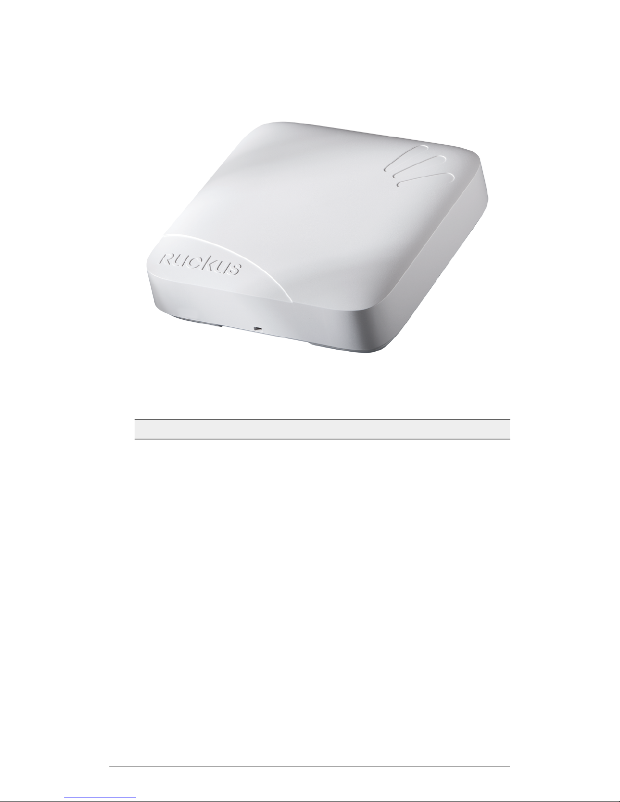
The following figure shows the top view of the 7982. For a description of each front panel
part, refer to the table below.
28
ZoneFlex Indoor Access Point Release 104.0 User Guide
Page 29
Introduction
Getting to Know the AP Features
Figure 13: 7982 top view
Table 10: 7982 front panel elements
Power LED
DIR LED
DescriptionLED
• Off: Off.
• Red: Boot up in process.
• Flashing Green: No routable IP address
• Green: On.
• Off: The AP is not being managed by a
Ruckus Wireless controller (standalone
mode).
• Green: The AP is being managed by a
Ruckus Wireless controller.
• Slow flashing green (one flash every two
seconds): The AP is being managed by
a controller, but is currently unable to
communicate with the controller.
• Fast flashing green (two flashes every
second): The AP is being managed by
a controller and is currently receiving
configuration settings (provisioning) or
an image update.
ZoneFlex Indoor Access Point Release 104.0 User Guide
29
Page 30

Introduction
Getting to Know the AP Features
DescriptionLED
AIR LED
2.4GHz LED
5GHz LED
• Off: The AP is operating in standalone
mode or operating as a root AP (RAP)
or a non-mesh AP.
• Green: The AP is functioning as a Mesh
AP (MAP), and the wireless signal to its
uplink AP is good.
• Fast flashing green (two flashes every
second): The AP is functioning as a
Mesh AP (MAP), and the wireless signal
to its uplink AP is fair.
• Slow flashing green (one flash every two
seconds): Mesh networking is enabled,
but the AP is still searching for a mesh
uplink.
• Off: The WLAN service is down.
• Green: The WLAN is up and at least
one client is associated.
• Amber: The WLAN is up. No clients are
associated.
• Off: The WLAN service is down.
• Amber: The WLAN is up, but no clients
or downlink MAPs are
associated/connected.
• Green: The WLAN is up and at least
one client is associated. No downlink
MAPs are connected.
• Slow flashing green (one flash every two
seconds): The WLAN is up and at least
one downlink MAP is connected. No
clients are associated.
• Fast flashing green (two flashes every
second): The WLAN is up, at least one
downlink MAP is connected, and at
least one client is associated.
Rear Panel Features
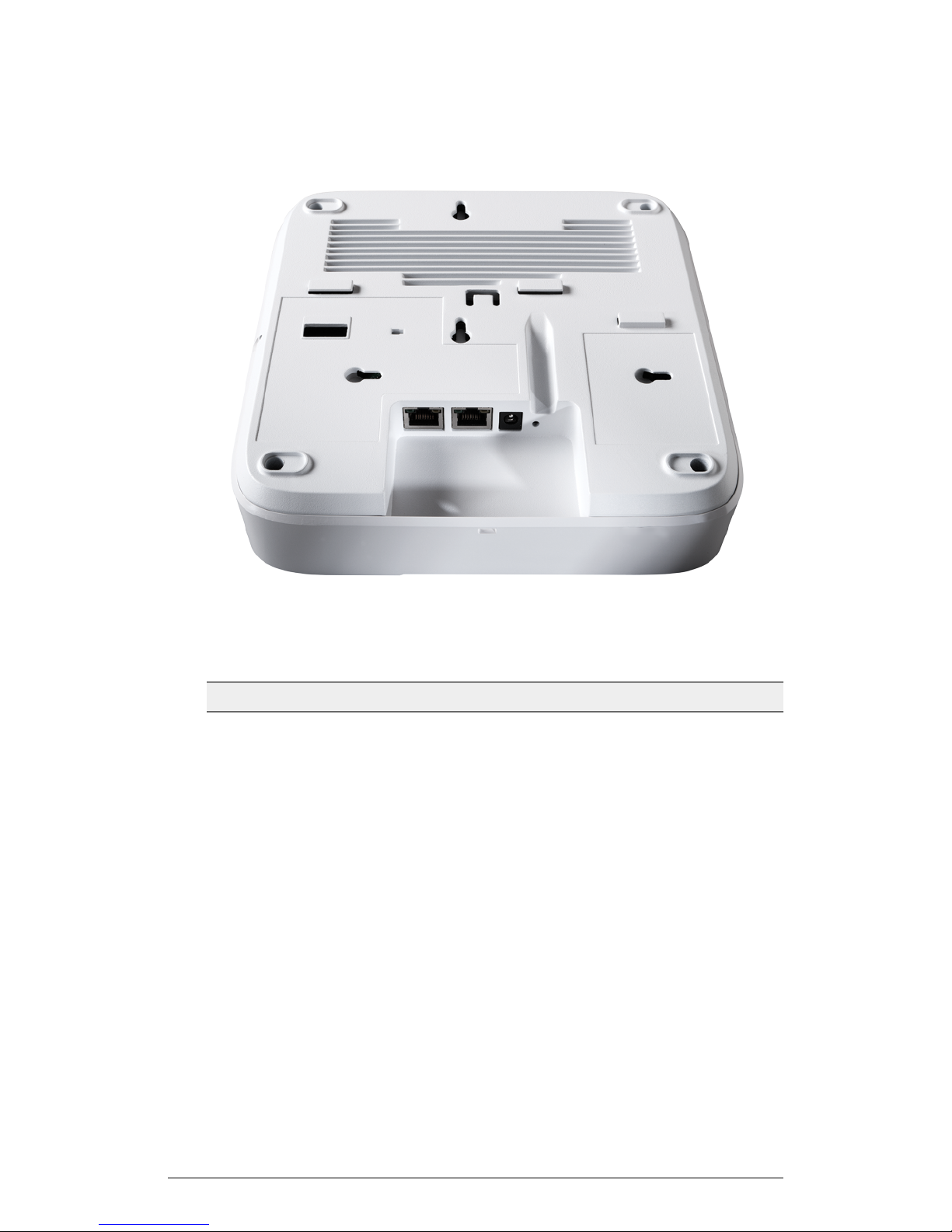
The following figure shows the rear panel of the 7982. For a description of each rear
panel part, refer to the table below.
30
ZoneFlex Indoor Access Point Release 104.0 User Guide
Page 31
Introduction
Getting to Know the AP Features
Figure 14: 7982 rear panel
Table 11: 7982 rear panel elements
ETHERNET + PoE Port
ETHERNET Port
12V 1.5A Power Socket
DescriptionItem Name
One RJ-45 port for a 10/100/1000 PoE
(Power over Ethernet, 802.3af/at)
connection (Note).
One RJ-45 port for a 10/100/1000
connection.
Connect the power adapter (12
VDC/1.25A) to this socket. Power can also
be supplied via the ETHERNET + PoE port.
ZoneFlex Indoor Access Point Release 104.0 User Guide
31
Page 32
Introduction
Getting to Know the AP Features
DescriptionItem Name
RESET Button
Pressing, and then quickly releasing this
internal button reboots the AP. Pressing
and holding it for six seconds resets the
AP to factory default settings.
CAUTION! Resetting the AP to factory
default settings erases all settings that you
configured previously.
NOTE Class 4 device. Some PoE+ switches reserve 30W for Class 4 device by default.
Ethernet Port LEDs
Refer to the following table for descriptions of Ethernet port LEDs and their behaviors.
The LEDs are not visible once the AP is installed.
Table 12: Behavior of Ethernet port LEDs on 7982
DescriptionLED
Not connectedOff
Connected to 10Mbps deviceAmber + Green
Connected to 100Mbps deviceAmber
Connected to 1000Mbps deviceGreen
WARNING! For units with Power over Ethernet (PoE). These products and all
interconnected equipment must be installed indoors within the same building, including
the associated LAN connections, as defined by Environment A of the IEEE 802.3af
Standard.
ZoneFlex H500 Wall Switch
The H500 is a high-capacity, high-performing, two-stream, dual-band, 802.11ac,
multimedia Wi-Fi AP wall switch with adaptive antenna technology for carriers and
enterprises.
NOTE The 100.x AP base images support standalone mode and FlexMaster (FM)
WLAN manager operation. The SmartZone software-compatible images only support
SCG, SZ and vSZ controllers. The ZD-compatible images only support ZD controllers.
32
ZoneFlex Indoor Access Point Release 104.0 User Guide
Page 33

Introduction
Getting to Know the AP Features
NOTE The H500 AP requires a minimum of AP base image 100.1.0 and later to operate,
or SCG 3.1 and later, vSZ 3.0 and later, SmartZone software 3.2 and later, or ZD 9.10
and later to operate.
NOTE The H500 is not supported by the ZoneDirector 1100.
The H500 has many options:
• It can be mounted on a standard USA- or EU-style single-gang wall outlet box.
• It can be powered by a customer-supplied IEEE 802.3af- or 802.3at-compliant PoE
switch or injector, or can be powered by an optional customer-ordered DC power
adapter.
• It has side cutouts for one or two bypass cables. The mounting bracket has locating
hooks to keep the bypass cables aligned with the cutouts when attaching the H500
to the mounting base.
• It can have a low-power (0.5W or less) customer-supplied USB device plugged in.
The USB port is intended for low-power devices such as BLE (Bluetooth low energy)
beacons.
The H500 has four LEDs, one RJ-45 connector, and a reset button on its rear panel,
and has one USB port (refer to Appendix A: AP Support for Bluetooth Low Energy
Devices on page 148, four RJ-45 connectors, and one DC power connector on its bottom
panel.
About Peripheral Devices
The H500 can supply power to USB devices and PoE-powered devices, and the power
supplied depends on the PoE power supplied to the H500.
• The USB port is intended for low-power devices such as BLE beacons. The maximum
power that the USB port can supply is 0.5W.
• The LAN1+PoE port is intended for PoE-powered peripheral devices such as IP
telephones.
For a description of the input and output power options, refer to the table below.
Table 13: H500 power options and available power out for PoE out and USB
Power Available for PoE Out and USBH500 Power Source
4W total802.3af PoE
802.3at PoE
DC power adapter (sold separately)
12.95W PoE Out (802.3af Class 3) and
0.5W USB
12.95W PoE Out (802.3af Class 3) and
0.5W USB
ZoneFlex Indoor Access Point Release 104.0 User Guide
33
Page 34
1
2
3
4
5
Introduction
Getting to Know the AP Features
Front Panel Features
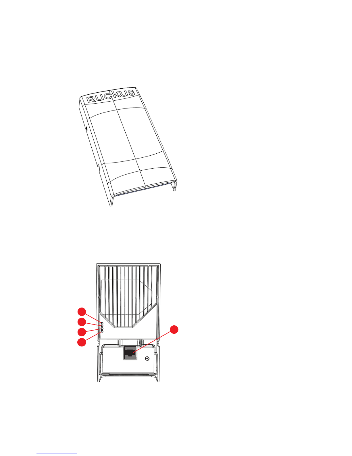
The following figure shows the front view of the H500.
Figure 15: H500 front view
Rear Panel Features
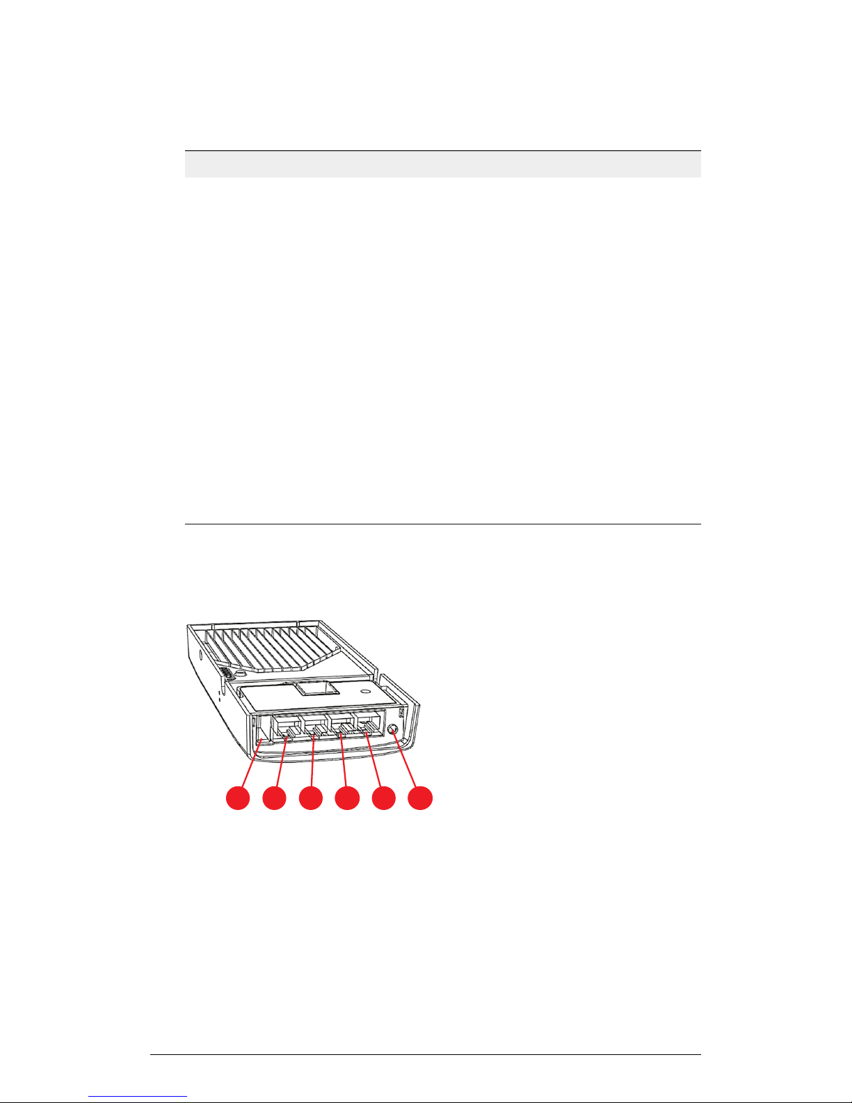
The following figure shows the rear panel of the H500. For a description of each rear
panel element, refer to the table below.
34
ZoneFlex Indoor Access Point Release 104.0 User Guide
Page 35

Figure 16: H500 rear view
Table 14: H500 rear panel elements
Introduction
Getting to Know the AP Features
DescriptionLED
PWR
CTL
2.4GHz WLAN
• Off: Off.
• Red: Boot up in process.
• Flashing Green: No routable IP address
• Green: On.
• Off: The AP is not being managed by a
Ruckus Wireless controller (standalone
mode).
• Green: The AP is being managed by a
Ruckus Wireless controller.
• Slow flashing green (one flash every two
seconds): The AP is being managed by
a Ruckus Wireless controller, but is
currently unable to communicate with
the controller.
• Fast flashing green (two flashes every
second): The AP is being managed by
a Ruckus Wireless controller and is
currently receiving configuration settings
(provisioning) or an image update.
• Off: The 2.4GHz WLAN service is down.
• Green: The WLAN service is up, at least
one client is associated, and signal
quality is good (RSSI >= 15).
• Amber: The WLAN service is up but no
clients are associated.
ZoneFlex Indoor Access Point Release 104.0 User Guide
35
Page 36
1 2 3
4
5
6
Introduction
Getting to Know the AP Features
DescriptionLED
5GHz WLAN
• Off: The 5GHz WLAN service is down.
Green: The WLAN service is up, at least
one client is associated, and no
downlink MAPs are connected.
• Slow flashing green (one flash every two
seconds): The WLAN service is up, at
least one downlink MAP is connected,
and no clients are associated.
• Fast flashing green (two flashes every
second): The WLAN service is up, at
least one downlink MAP is connected,
and at least one client is associated.
• Amber: The WLAN service is up, but no
clients or downlink MAPs are
associated or connected.
PoE In Port
One RJ-45 port for a 10/100/1000 PoE
(Power over Ethernet, 802.3af/at Class 3
or 4) connection.
Bottom Panel
The following figure shows the bottom view of the H500. For a description of each bottom
panel part, refer to the table below.
36
ZoneFlex Indoor Access Point Release 104.0 User Guide
Page 37
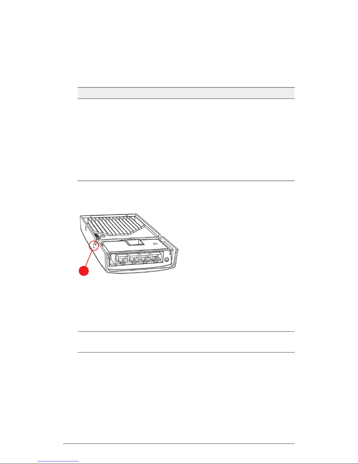
Figure 17: H500 bottom panel
1
Table 15: H500 bottom panel elements
DescriptionItem Name
Introduction
Getting to Know the AP Features
USB port
Optional USB connector (refer to About Peripheral Devices and
Appendix A: AP Support for Bluetooth Low Energy Devices on page 148).
10/100 RJ-45 Ethernet Port.LAN4 port
10/100 RJ-45 Ethernet Port.LAN3 port
10/100 RJ-45 Ethernet Port.LAN2 port
LAN1+PoE
port
10/100 RJ-45 LAN port with PoE out. Supports 802.3af PSE Class 2
or 3 (depending on power input; refer to About Peripheral Devices).
Optional 48VDC power input connector.48VDC port
Reset Buttons
Two reset buttons on the left side of the AP are used to reboot or factory reset the AP.
Figure 18: Reset buttons
Use a straightened paper clip to press and release the Hard Reset button for eight
seconds or more to reset the AP to factory defaults. Use a straightened paper clip to
press and hold the Soft Reset button to reboot the AP. This is the same as removing
power and then and restoring power to the H500.
NOTE Resetting the AP to factory default settings erases all previously configured
settings.
ZoneFlex Indoor Access Point Release 104.0 User Guide
37
Page 38
Introduction
Getting to Know the AP Features
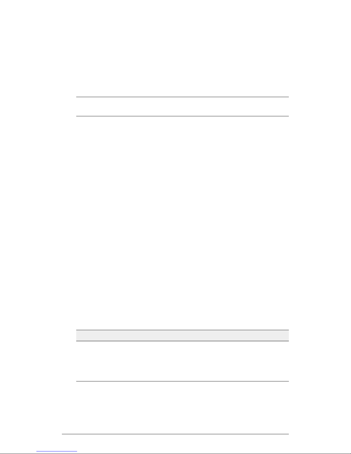
ZoneFlex H510 Wall Switch
H510 is an 802.11ac Wave 2 dual band access point with integrated 5-port Ethernet,
in a form factor which allows mounting to electrical outlet boxes. The H510 is the 11ac
Wave 2 successor to the H500.
NOTE The H510 requires a minimum of AP base image 104.0 and later to operate, or
SZ 3.4 and later, or ZD 9.13.1 and later to operate.
The H510 has many options:
• It can be mounted on a standard USA- or EU-style single-gang wall outlet box.
• It can be powered by a customer-supplied IEEE 802.3af- or 802.3at-compliant PoE
switch or injector, or can be powered by an optional customer-ordered DC power
adapter.
• It has bottom cutouts for one or two bypass cables. The mounting bracket has
locating hooks to keep the bypass cables aligned with the cutouts when attaching
the H510 to the mounting base.
• It can have a low-power (0.5W or less) customer-supplied USB device plugged in.
The USB port is intended for low-power devices such as BLE (Bluetooth low energy)
beacons.
The H510 has four LEDs, one RJ-45 connector, and a reset button on its rear panel,
and has one USB port (refer to Appendix A: AP Support for Bluetooth Low Energy
Devices on page 148, four RJ-45 connectors, and one DC power connector on its bottom
panel.
About Peripheral Devices
The H510 can supply power to USB devices and PoE-powered devices, and the power
supplied depends on the PoE power supplied to the H510.
• The USB port is intended for low-power devices such as BLE beacons. The maximum
power that the USB port can supply is 0.5W.
• The LAN1+PoE port is intended for PoE-powered peripheral devices such as IP
telephones.
For a description of the input and output power options, refer to the table below.
Table 16: H510 power options and available power out for PoE out and USB
Power Available for PoE Out and USBH510 Power Source
4W total802.3af PoE
12.95W PoE Out (802.3af Class 3) and 0.5W USB802.3at PoE
12.95W PoE Out (802.3af Class 3) and 0.5W USBDC power adapter (sold
separately)
38
ZoneFlex Indoor Access Point Release 104.0 User Guide
Page 39
Front Panel Features
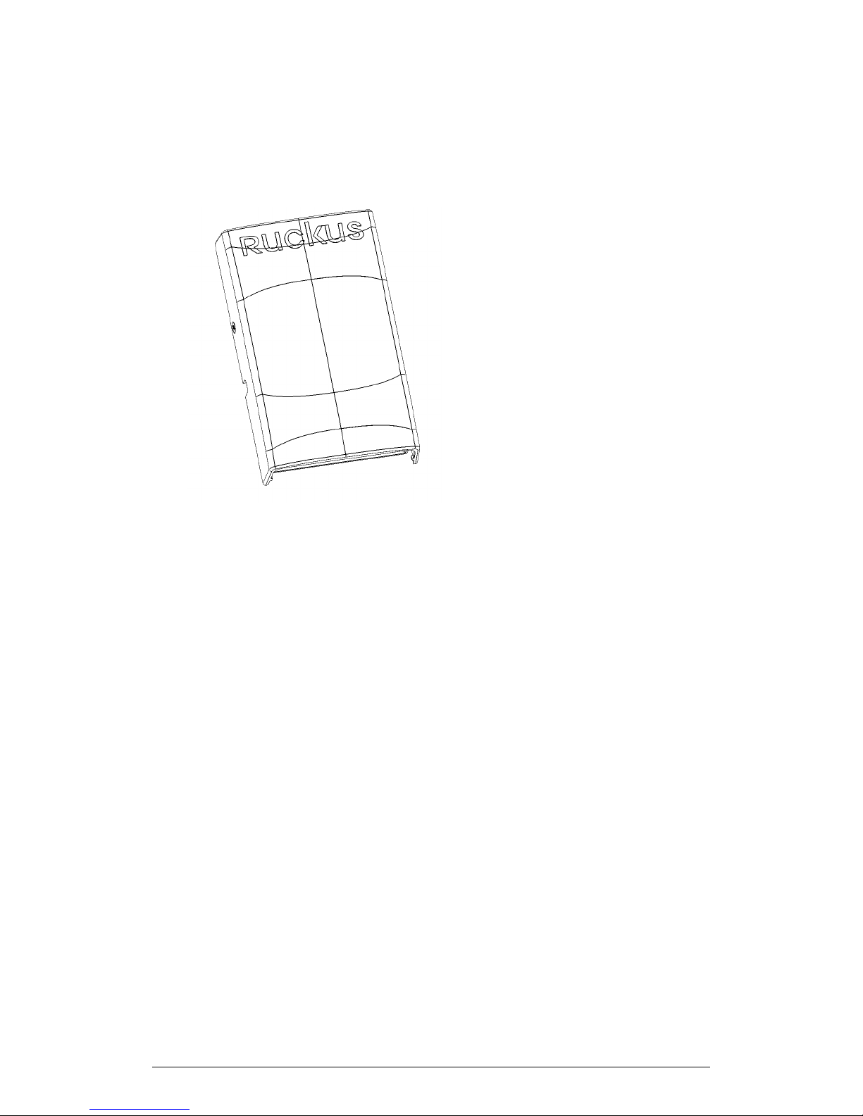
The following figure shows the front view of the H510.
Introduction
Getting to Know the AP Features
Figure 19: H510 front view
Rear Panel Features
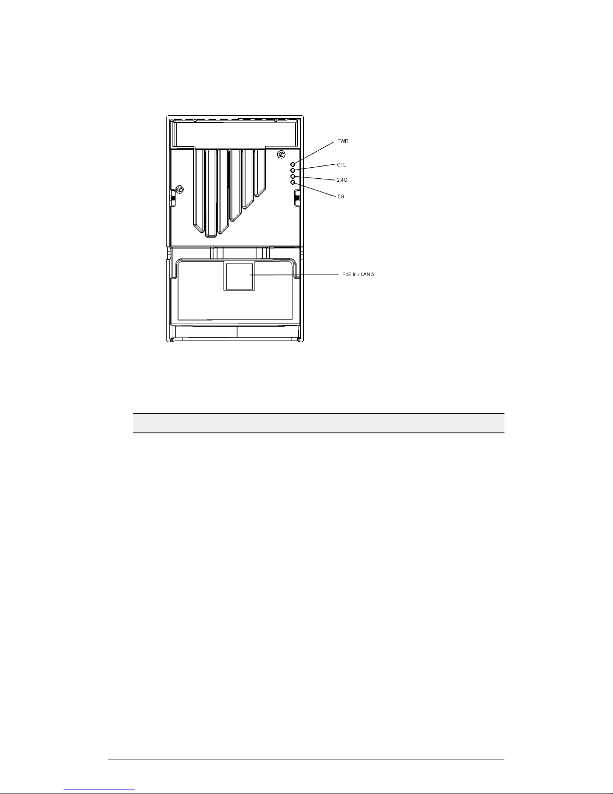
The following figure shows the rear panel of the H510. For a description of each rear
panel element, refer to the table below.
ZoneFlex Indoor Access Point Release 104.0 User Guide
39
Page 40
Introduction
Getting to Know the AP Features
Figure 20: H510 rear view
Table 17: H510 rear panel elements
DescriptionLED
PWR
CTL
2.4GHz WLAN
• Off: Off.
• Red: Boot up in process.
• Flashing Green: No routable IP address
• Green: On.
• Off: The AP is not being managed by a Ruckus Wireless controller
(standalone mode).
• Green: The AP is being managed by a Ruckus Wireless controller.
• Slow flashing green (one flash every two seconds): The AP is being
managed by a Ruckus Wireless controller, but is currently unable
to communicate with the controller.
• Fast flashing green (two flashes every second): The AP is being
managed by a Ruckus Wireless controller and is currently receiving
configuration settings (provisioning) or an image update.
• Off: The 2.4GHz WLAN service is down.
• Green: The WLAN service is up, at least one client is associated,
and signal quality is good (RSSI >= 15).
• Amber: The WLAN service is up but no clients are associated.
40
ZoneFlex Indoor Access Point Release 104.0 User Guide
Page 41
Introduction
Getting to Know the AP Features
DescriptionLED
5GHz WLAN
• Off: The 5GHz WLAN service is down. Green: The WLAN service
is up, at least one client is associated, and no downlink MAPs are
connected.
• Slow flashing green (one flash every two seconds): The WLAN
service is up, at least one downlink MAP is connected, and no
clients are associated.
• Fast flashing green (two flashes every second): The WLAN service
is up, at least one downlink MAP is connected, and at least one
client is associated.
• Amber: The WLAN service is up, but no clients or downlink MAPs
are associated or connected.
PoE In Port
One RJ-45 port for a 10/100/1000 PoE (Power over Ethernet,
802.3af/at Class 3 or 4) connection.
Bottom Panel
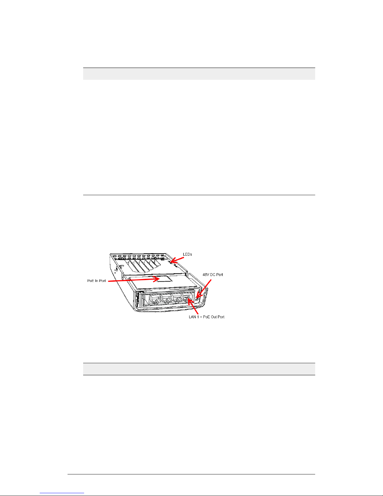
The following figure shows the bottom view of the H510. For a description of each bottom
panel part, refer to the table below.
Figure 21: H510 bottom panel
Table 18: H510 bottom panel elements
USB port
ZoneFlex Indoor Access Point Release 104.0 User Guide
DescriptionItem Name
Optional USB connector (refer to
Appendix A: AP Support for Bluetooth Low Energy Devices on page 148).
10/100 RJ-45 Ethernet Port.LAN4 port
10/100 RJ-45 Ethernet Port.LAN3 port
41
Page 42
Introduction
Getting to Know the AP Features
DescriptionItem Name
10/100 RJ-45 Ethernet Port.LAN2 port
LAN1+PoE
port
10/100 RJ-45 LAN port with PoE out. Supports 802.3af PSE Class 2
or 3 (depending on power input; refer to About Peripheral Devices).
Optional 48VDC power input connector.48VDC port
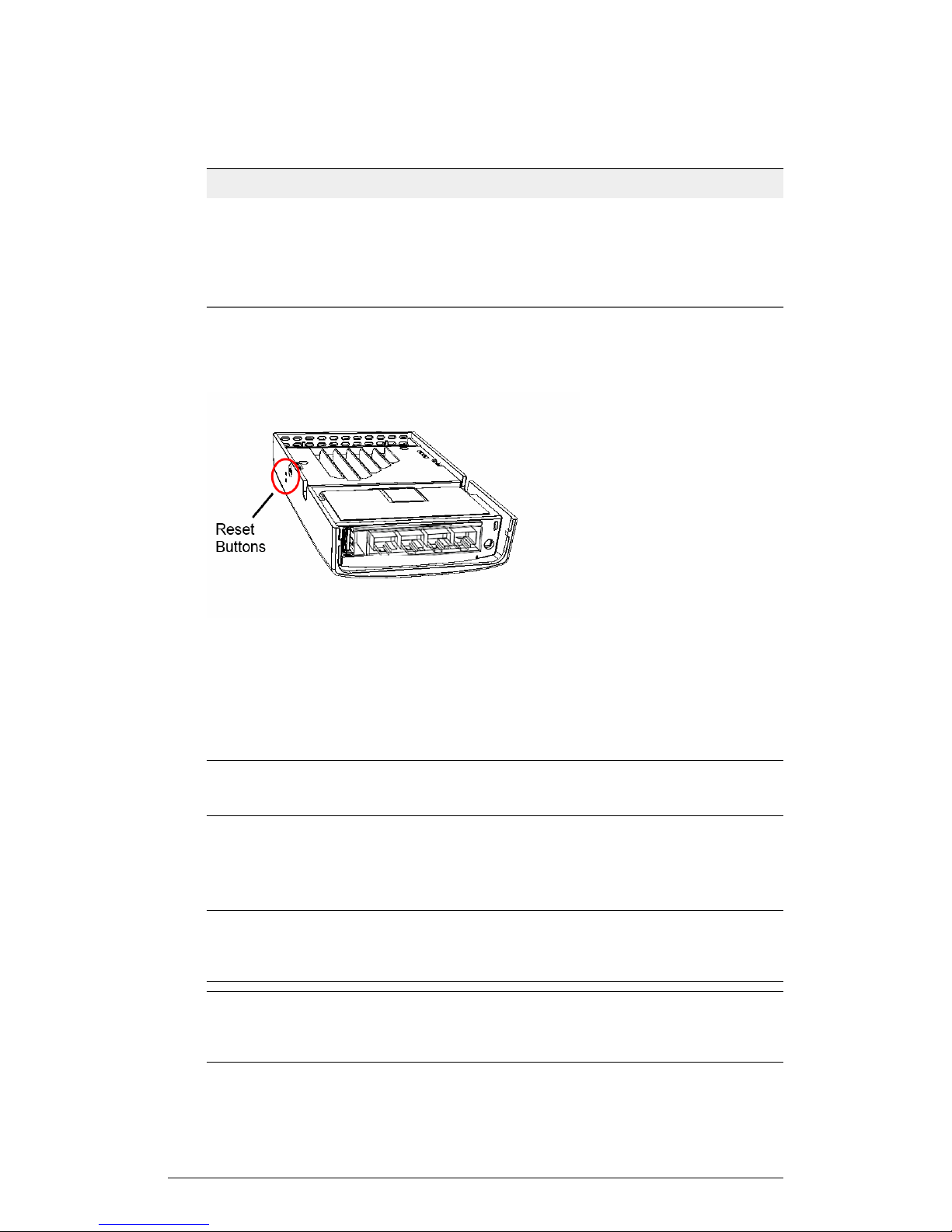
Reset Buttons
Two reset buttons on the left side of the AP are used to reboot or factory reset the AP.
Figure 22: Reset buttons
Use a straightened paper clip to press and release the Hard Reset button for eight
seconds or more to reset the AP to factory defaults. Use a straightened paper clip to
press and hold the Soft Reset button to reboot the AP. This is the same as removing
power and then and restoring power to the H510.
NOTE Resetting the AP to factory default settings erases all previously configured
settings.
ZoneFlex R300
The R300 is a high-capacity, high-performing, two-stream, dual-band, 802.11n AP with
adaptive antenna technology for carriers and enterprises.
NOTE The 100.x AP base images support standalone mode and FlexMaster (FM)
WLAN manager operation. The SmartZone software-compatible images only support
SCG, SZ and vSZ controllers. The ZD-compatible images only support ZD controllers.
NOTE The R300 AP requires a minimum of AP base image 100.0.0 and later to operate,
or SCG 2.5 and later, vSZ 2.5 and later, SmartZone software 3.2 and later, or ZD 9.6.1
and later to operate.
42
ZoneFlex Indoor Access Point Release 104.0 User Guide
Page 43
Introduction
Getting to Know the AP Features
NOTE The R300 is an entry level 802.11n dual-band AP that does not support the
Smart Mesh or Spectrum Analysis features, and supports a maximum of 250 unencrypted
clients.
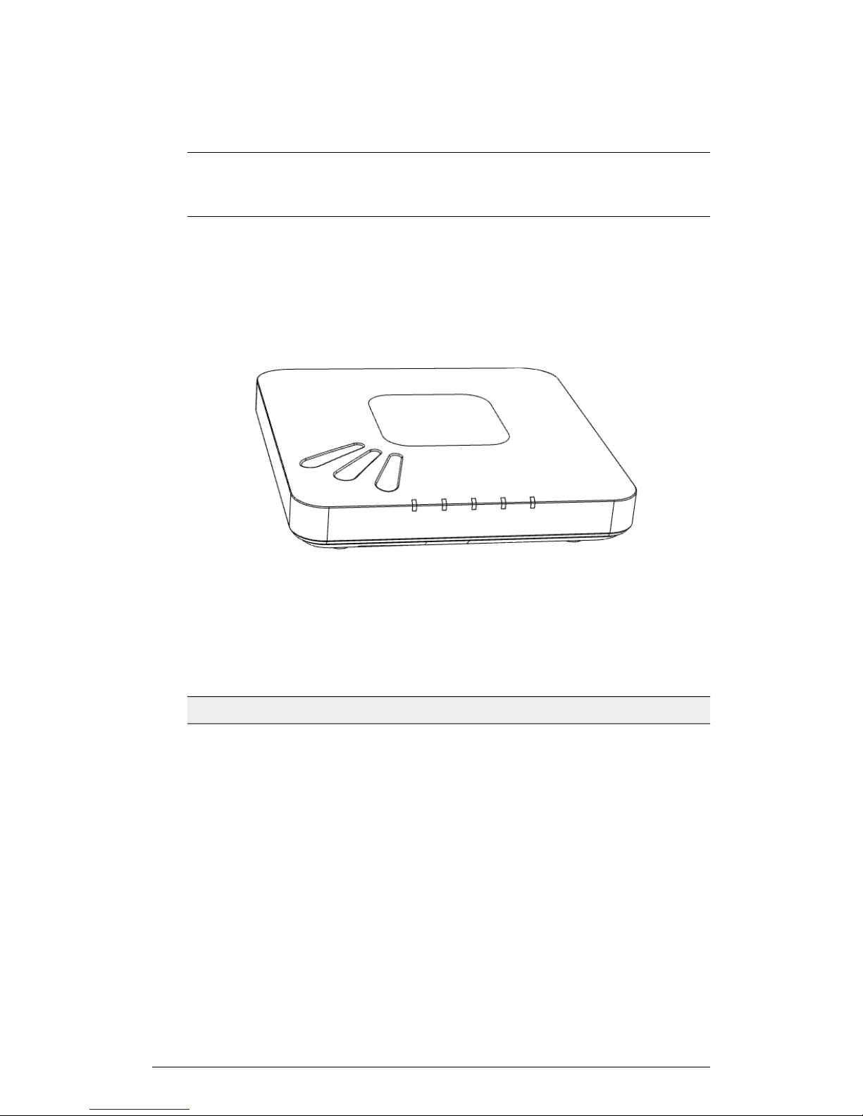
Front View Features
The R300 includes five LEDs on its front panel and buttons and connectors on its rear
panel.
Figure 23: R300 front view
Table 19: R300 front panel elements
PWR LED
DescriptionLED
• Off: Off.
• Red: Boot up in process.
• Flashing Green: No routable IP address
• Green: On.
Not used in this model.OPT LED
ZoneFlex Indoor Access Point Release 104.0 User Guide
43
Page 44

Introduction
Getting to Know the AP Features
DescriptionLED
DIR LED
2.4G LED (WLAN)
5G LED (WLAN)
• Off: The AP is not being managed by a
controller (standalone mode).
• Green: The AP is being managed by a
controller.
• Slow flashing green (one flash every two
seconds): The AP is being managed by
a controller, but is currently unable to
communicate with the controller.
• Fast flashing green (two flashes every
second): The AP is being managed by
a controller and is currently receiving
configuration settings (provisioning) or
an image update.
• Off: The WLAN service is down.
• Green: The WLAN service is up and at
least one client is associated.
• Amber: The WLAN service is up and no
clients are associated.
• Off: The WLAN service is down.
• Green: The WLAN service is up and at
least one client is associated.
• Amber: The WLAN service is up and no
clients are associated.
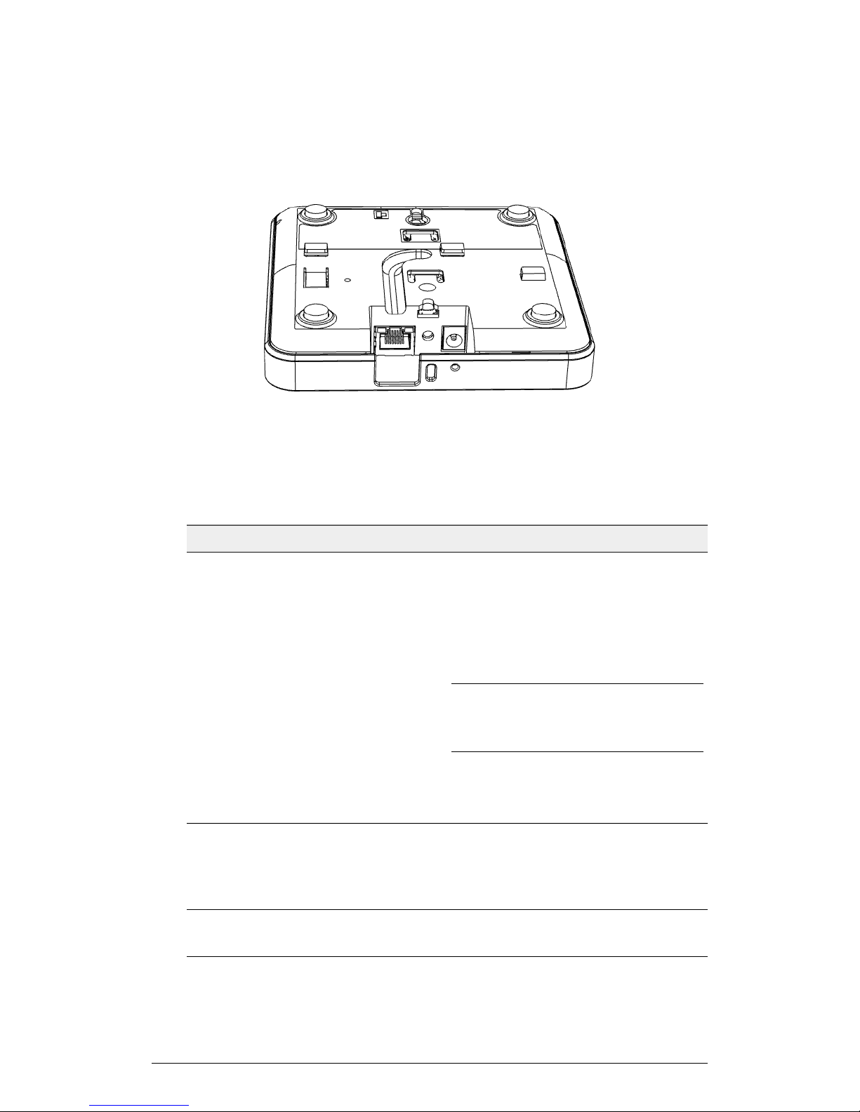
Rear Panel Features
The rear panel of the R300 includes one 10/100/1000 PoE Ethernet port, power socket
and reset button. See the table below for a description of each rear panel part.
44
ZoneFlex Indoor Access Point Release 104.0 User Guide
Page 45
Introduction
Getting to Know the AP Features
Figure 24: R300 rear panel
Table 20: R300 rear panel elements
DescriptionItem Name
10/100/1000+PoE Port
RST Button
Power
One RJ-45 port for a 10/100/1000 PoE
(Power over Ethernet, 802.3af) connection.
Pressing, and then quickly releasing this
internal button reboots the AP. Pressing
and holding it for six seconds resets the
AP to factory default settings.
NOTE Resetting the AP to factory default
settings erases all previously configured
settings.
Connect the power adapter (12
VDC/1.25A) to this socket. Power can also
be supplied via the 10/100/1000 PoE port.
ZoneFlex R310
The R310 is an entry level two-stream, dual-band, 802.11ac Access Point with adaptive
antenna technology for carriers and enterprises.
NOTE The minimum software revision for the R310 is standalone AP base image 102.0
or later, SmartZone 3.2 or later, or ZoneFlex 9.12.2 or later.
ZoneFlex Indoor Access Point Release 104.0 User Guide
45
Page 46
Introduction
Getting to Know the AP Features
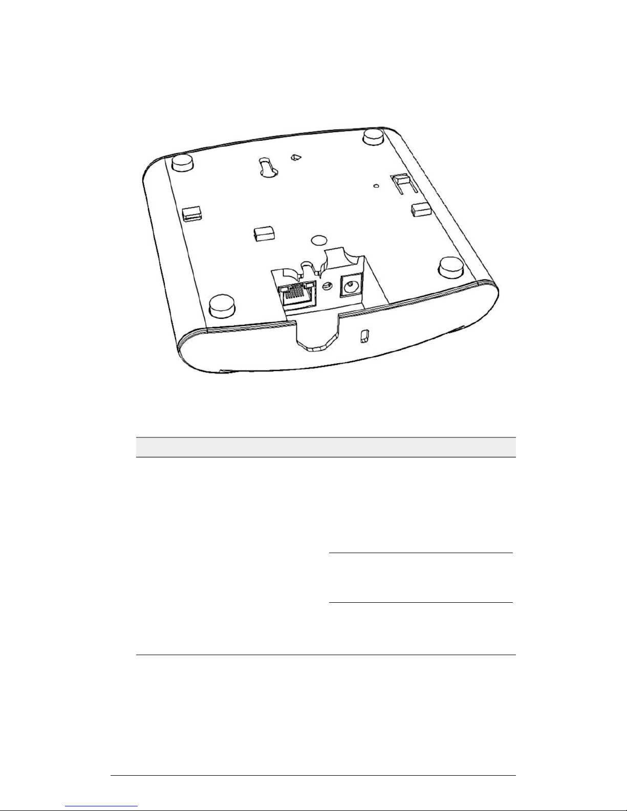
NOTE The R310 is an entry level 802.11ac dual-band AP that does not support the
Smart Mesh or Spectrum Analysis features, and supports a maximum of 100 unencrypted
clients.
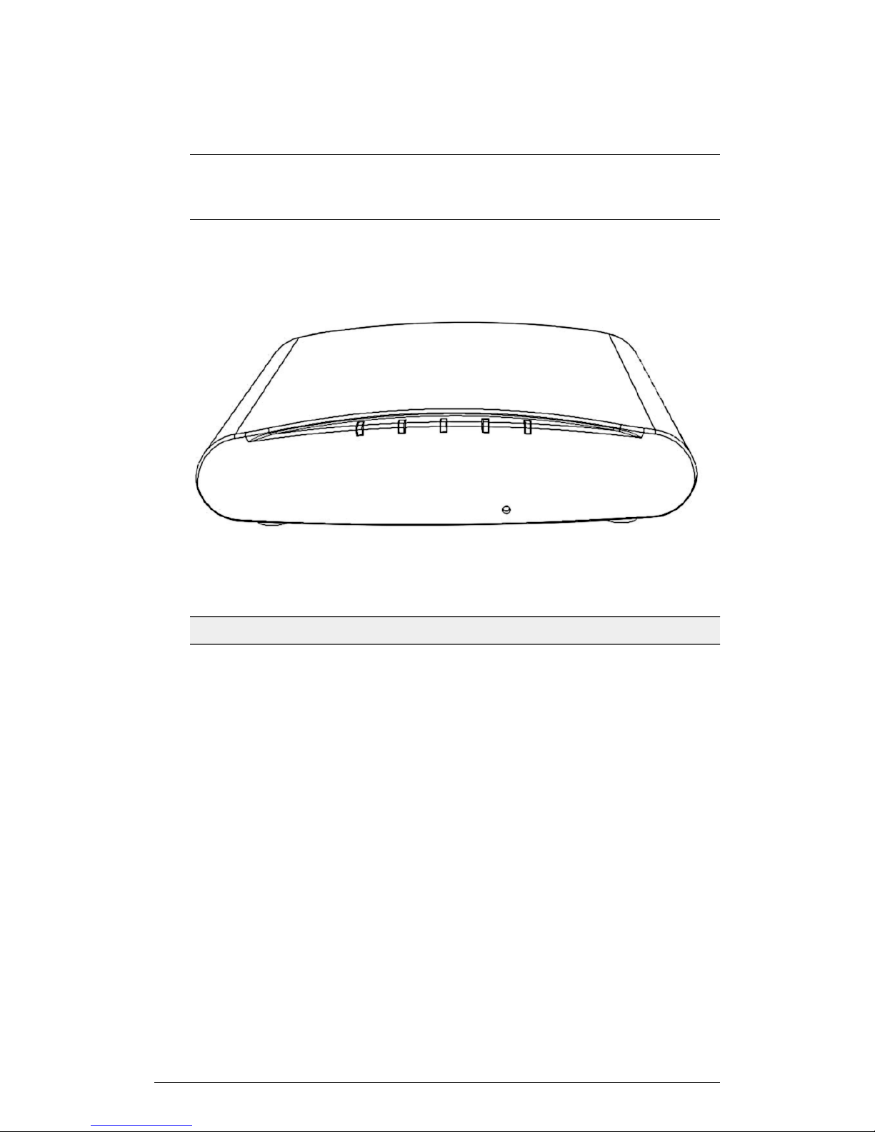
Front View Features
The R310 includes five LEDs on its front panel and buttons and connectors on its rear
panel.
Figure 25: R310 front view
Table 21: R310 front panel elements
PWR LED
DescriptionLED
• Off: Off.
• Red: Boot up in process.
• Flashing Green: No routable IP address
• Green: On.
Not used in this model.OPT LED
46
ZoneFlex Indoor Access Point Release 104.0 User Guide
Page 47

Introduction
Getting to Know the AP Features
DescriptionLED
DIR LED
2.4G LED (WLAN)
5G LED (WLAN)
• Off: The AP is not being managed by a
controller (standalone mode).
• Green: The AP is being managed by a
controller.
• Slow flashing green (one flash every two
seconds): The AP is being managed by
a controller, but is currently unable to
communicate with the controller.
• Fast flashing green (two flashes every
second): The AP is being managed by
a controller and is currently receiving
configuration settings (provisioning) or
an image update.
• Off: The WLAN service is down.
• Green: The WLAN service is up and at
least one client is associated.
• Amber: The WLAN service is up and no
clients are associated.
• Off: The WLAN service is down.
• Green: The WLAN service is up and at
least one client is associated.
• Amber: The WLAN service is up and no
clients are associated.
Rear Panel Features
The rear panel of the R310 includes one 10/100/1000 PoE Ethernet port, power socket
and reset button. See the table below for a description of each rear panel part.
ZoneFlex Indoor Access Point Release 104.0 User Guide
47
Page 48
Introduction
Getting to Know the AP Features
Figure 26: R310 rear panel
Table 22: R310 rear panel elements
10/100/1000+PoE Port
RST Button
Power
DescriptionItem Name
One RJ-45 port for a 10/100/1000 PoE
(Power over Ethernet, 802.3af) connection.
Pressing, and then quickly releasing this
internal button reboots the AP. Pressing
and holding it for six seconds resets the
AP to factory default settings.
NOTE Resetting the AP to factory default
settings erases all previously configured
settings.
Connect the power adapter (12
VDC/1.25A) to this socket. Power can also
be supplied via the 10/100/1000 PoE port.
48
ZoneFlex Indoor Access Point Release 104.0 User Guide
Page 49
Getting to Know the AP Features
ZoneFlex R500
The R500 is a high-performance 2x2:2 802.11ac dual-band AP designed for medium
client density deployments.
NOTE The 100.x AP base images support standalone mode and FlexMaster (FM)
WLAN manager operation. The SmartZone software-compatible images only support
SCG, SZ and vSZ controllers. The ZD-compatible images only support ZD controllers.
NOTE The R500 AP requires a minimum of standalone AP base image 100.0.0 and
later to operate, or SCG 2.5.1 and later, vSZ 3.0 and later, SmartZone software 3.2 and
later, or ZD 9.8.1 and later to operate.
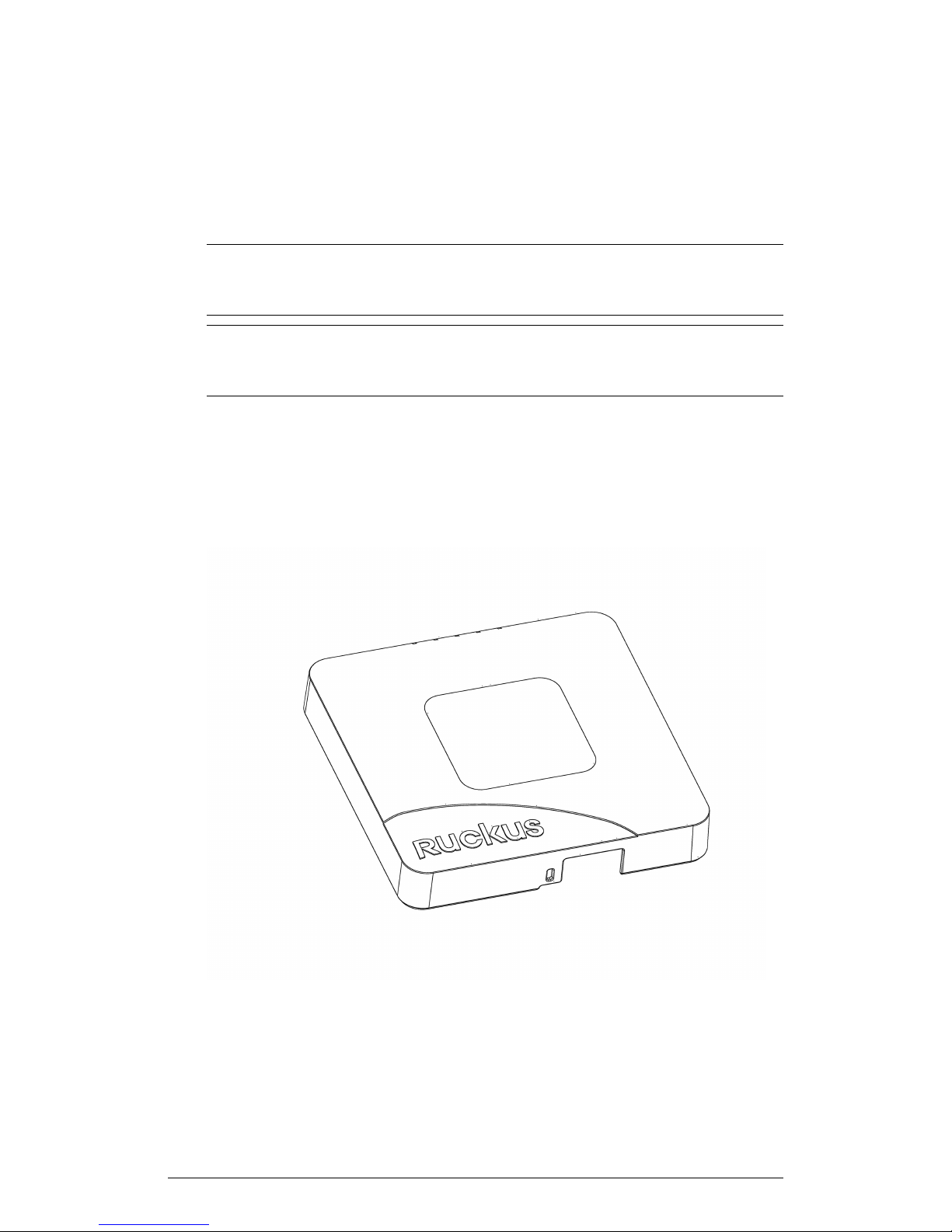
The R500 includes five LEDs on its front panel and buttons and connectors on its rear
panel.
Front View Features
The following figure shows the top view of the R500. For a description of the front panel
LEDs, refer to the table below.
Introduction
ZoneFlex Indoor Access Point Release 104.0 User Guide
49
Page 50

Introduction
Getting to Know the AP Features
Figure 27: R500 top view
Table 23: R500 front panel LEDs
DescriptionLED
PWR
DIR
AIR
• Off: Off.
• Red: Boot up in process.
• Flashing Green: No routable IP address
• Green: On.
• Off: The AP is not being managed by a
controller (standalone mode).
• Green: The AP is being managed by a
controller.
• Slow flashing green (one flash every two
seconds): The AP is being managed by
a controller, but is currently unable to
communicate with the controller.
• Fast flashing green (two flashes every
second): The AP is being managed by
a controller and is currently receiving
configuration settings (provisioning) or
an image update.
• Off: The AP is operating in standalone
mode or operating as a root AP (RAP)
or a non-mesh AP.
• Green: The AP is functioning as a Mesh
AP (MAP), and the wireless signal to its
uplink AP is good.
• Fast flashing green (two flashes every
second): The AP is functioning as a
Mesh AP (MAP), and the wireless signal
to its uplink AP is fair.
• Slow flashing green (one flash every two
seconds): Mesh networking is enabled,
but the AP is still searching for a mesh
uplink.
2.4G
50
• Off: The WLAN service is down.
• Green: The WLAN is up and at least
one client is associated.
• Amber: The WLAN is up. No clients are
associated.
ZoneFlex Indoor Access Point Release 104.0 User Guide
Page 51
Introduction
Getting to Know the AP Features
DescriptionLED
5G
• Off: The WLAN service is down.
• Amber: The WLAN is up, but no clients
or downlink MAPs are
associated/connected.
• Green: The WLAN is up and at least
one client is associated. No downlink
MAPs are connected.
• Slow flashing green (one flash every two
seconds): The WLAN is up and at least
one downlink MAP is connected. No
clients are associated.
• Fast flashing green (two flashes every
second): The WLAN is up, at least one
downlink MAP is connected, and at
least one client is associated.
Rear Panel
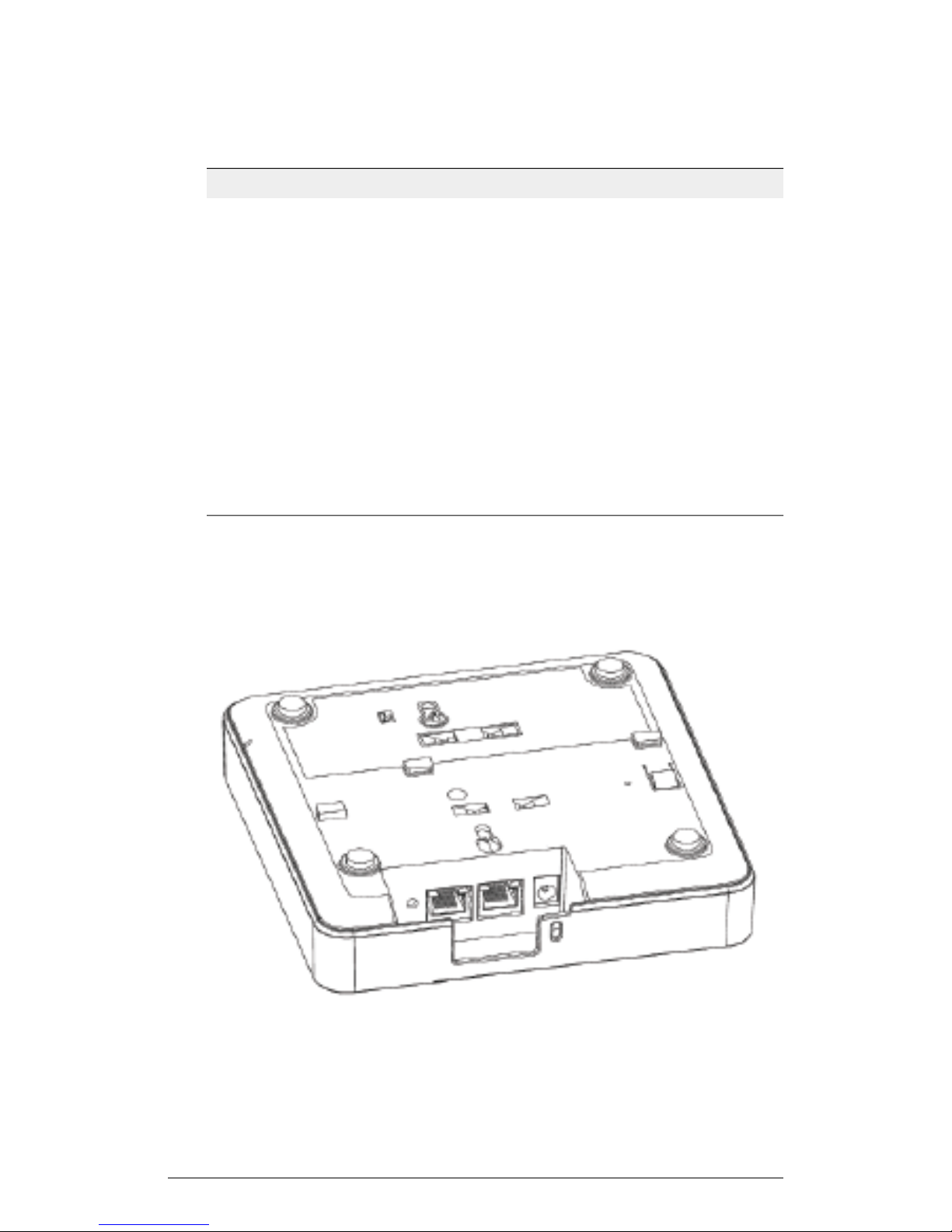
The rear panel of the R500 includes one 10/100/1000 PoE Ethernet port, 10/100/1000
Ethernet port, power socket and reset button. See the table below for a description of
each rear panel part.
ZoneFlex Indoor Access Point Release 104.0 User Guide
51
Page 52
Introduction
Getting to Know the AP Features
Figure 28: R500 rear panel
Table 24: R500 Rear panel element descriptions
DescriptionLabel
RESET Button
Pressing, and then quickly releasing this
button reboots the AP. Pressing and
holding it for six seconds resets the AP to
factory default settings.
NOTE Resetting the AP to factory default
settings erases all settings that you
configured previously.
PoE Port
One RJ-45 port for a 10/100/1000 PoE
(Power over Ethernet, 802.3af/at)
connection. (The R500 is a Class 3 device.)
Ethernet Port
One RJ-45 port for a 10/100/1000
connection.
12VDC
Connect the power adapter (12
VDC/1.25A) to this socket. Power can also
be supplied via the 10/100/1000 PoE port.
Ethernet Port LEDs
Table 25: Behavior of Ethernet port LEDs on the R500
DescriptionLED
Not connectedOff
Connected to 10Mbps deviceAmber + Green
Connected to 100Mbps deviceAmber
Connected to 1000Mbps deviceGreen
WARNING! For units using Power over Ethernet (PoE). These products and all
interconnected equipment must be installed indoors within the same building, including
the associated LAN connections, as defined by Environment A of the IEEE 802.3af
Standard.
52
ZoneFlex Indoor Access Point Release 104.0 User Guide
Page 53
Getting to Know the AP Features
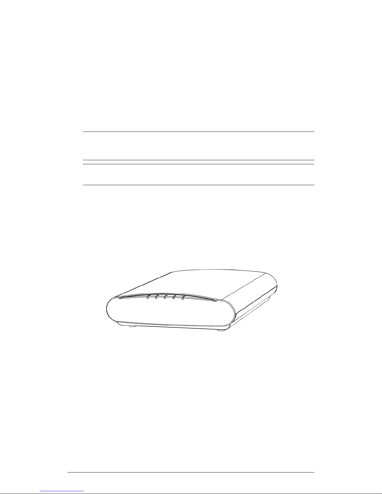
ZoneFlex R510
The R510 is a high-performance 2x2:2 802.11ac Wave 2 dual-band AP designed for
medium client density deployments.
The R510 has a USB port on its bottom panel. The USB port is intended for low-power
devices such as BLE (Bluetooth low energy) beacons. The maximum power that the
USB port can supply is 0.5W. Refer to Appendix A: AP Support for Bluetooth Low Energy
Devices on page 148 for more information.
NOTE The 104.x AP base images support standalone mode and FlexMaster (FM)
WLAN manager operation. The SmartZone software-compatible images only support
SCG, SZ and vSZ controllers. The ZD-compatible images only support ZD controllers.
NOTE The R510 AP requires a minimum of standalone AP base image 104.0 and later,
or SmartZone 3.4 and later, or ZoneDirector 9.13 and later to operate.
The R510 includes five LEDs on its front panel and buttons and connectors on its rear
panel.
Introduction
Front View Features
The following figure shows the top view of the R510. For a description of the front panel
LEDs, refer to the table below.
ZoneFlex Indoor Access Point Release 104.0 User Guide
53
Page 54

Introduction
Getting to Know the AP Features
Figure 29: R510 top view
Table 26: R510 front panel LEDs
DescriptionLED
PWR
DIR
AIR
• Off: Off.
• Red: Boot up in process.
• Flashing Green: No routable IP address
• Green: On.
• Off: The AP is not being managed by a
controller (standalone mode).
• Green: The AP is being managed by a
controller.
• Slow flashing green (one flash every two
seconds): The AP is being managed by
a controller, but is currently unable to
communicate with the controller.
• Fast flashing green (two flashes every
second): The AP is being managed by
a controller and is currently receiving
configuration settings (provisioning) or
an image update.
• Off: The AP is operating in standalone
mode or operating as a root AP (RAP)
or a non-mesh AP.
• Green: The AP is functioning as a Mesh
AP (MAP), and the wireless signal to its
uplink AP is good.
• Fast flashing green (two flashes every
second): The AP is functioning as a
Mesh AP (MAP), and the wireless signal
to its uplink AP is fair.
• Slow flashing green (one flash every two
seconds): Mesh networking is enabled,
but the AP is still searching for a mesh
uplink.
2.4G
54
• Off: The WLAN service is down.
• Green: The WLAN is up and at least
one client is associated.
• Amber: The WLAN is up. No clients are
associated.
ZoneFlex Indoor Access Point Release 104.0 User Guide
Page 55
Introduction
Getting to Know the AP Features
DescriptionLED
5G
• Off: The WLAN service is down.
• Amber: The WLAN is up, but no clients
or downlink MAPs are
associated/connected.
• Green: The WLAN is up and at least
one client is associated. No downlink
MAPs are connected.
• Slow flashing green (one flash every two
seconds): The WLAN is up and at least
one downlink MAP is connected. No
clients are associated.
• Fast flashing green (two flashes every
second): The WLAN is up, at least one
downlink MAP is connected, and at
least one client is associated.
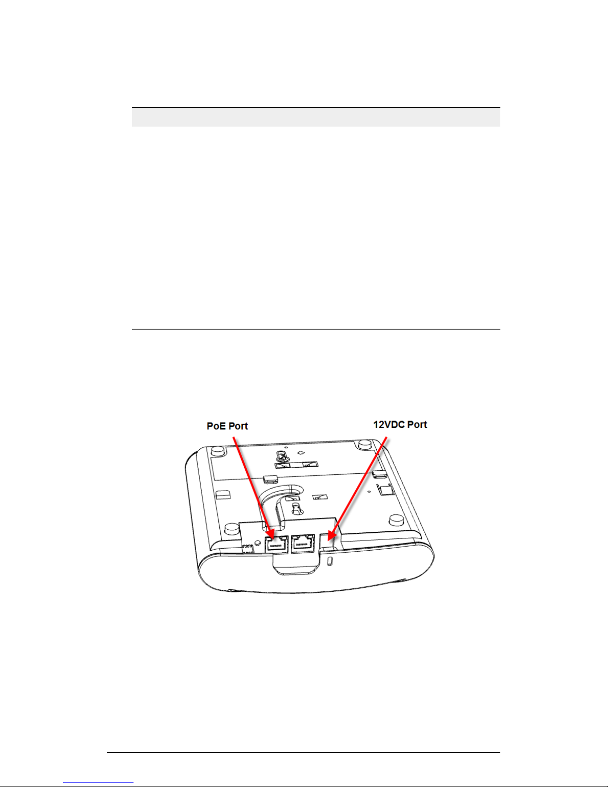
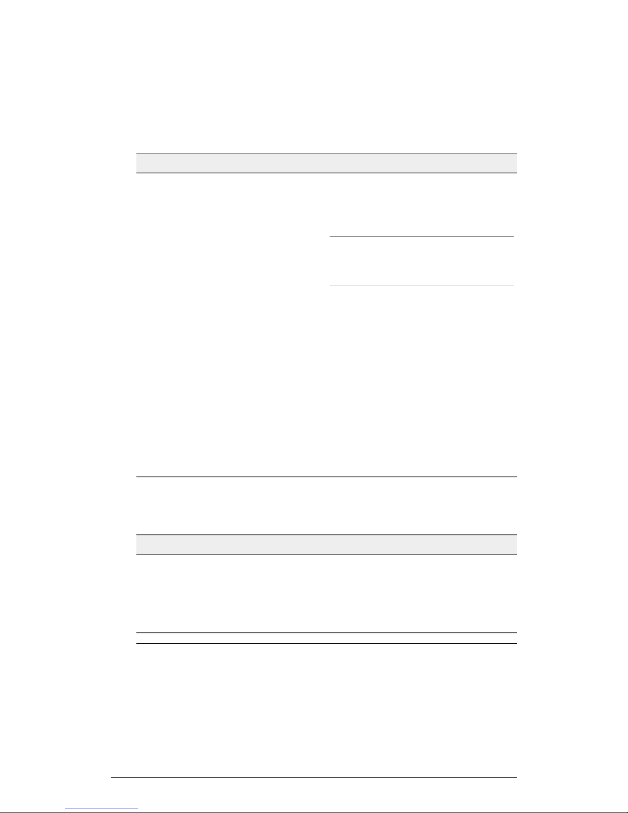
Rear Panel
The rear panel of the R510 includes one 10/100/1000 PoE Ethernet port, 10/100/1000
Ethernet port, power socket and reset button. See the table below for a description of
each rear panel part.
ZoneFlex Indoor Access Point Release 104.0 User Guide
55
Page 56
Introduction
Getting to Know the AP Features
Figure 30: R510 rear panel
Table 27: R510 Rear panel element descriptions
DescriptionLabel
RESET Button
PoE Port
Ethernet Port
12VDC
USB Port
Pressing, and then quickly releasing this
button reboots the AP. Pressing and
holding it for six seconds resets the AP to
factory default settings.
NOTE Resetting the AP to factory default
settings erases all settings that you
configured previously.
One RJ-45 port for a 10/100/1000 PoE
(Power over Ethernet, 802.3af/at)
connection. (The R510 is a Class 3 device.)
One RJ-45 port for a 10/100/1000
connection.
Connect the power adapter (12
VDC/1.25A) to this socket. Power can also
be supplied via the 10/100/1000 PoE port.
The R510 can have a low-power (0.5W or
less) customer-supplied USB device
plugged in. The USB device is hidden after
the R510 is attached to its mounting base.
Ethernet Port LEDs
Table 28: Behavior of Ethernet port LEDs on the R510
WARNING! For units using Power over Ethernet (PoE). These products and all
interconnected equipment must be installed indoors within the same building, including
56
DescriptionLED
Not connectedOff
Connected to 10Mbps deviceAmber + Green
Connected to 100Mbps deviceAmber
Connected to 1000Mbps deviceGreen
ZoneFlex Indoor Access Point Release 104.0 User Guide
Page 57
Getting to Know the AP Features
the associated LAN connections, as defined by Environment A of the IEEE 802.3af
Standard.
ZoneFlex R600
The R600 is a high-performance 3x3:3 802.11ac dual-band AP designed for mediumto high-density wireless networks.
NOTE The R600 AP requires a minimum of AP base image 100.0.0 and later to operate,
or SCG 2.5.1 and later, vSZ 3.0 and later, SmartZone software 3.2 and later, or ZD 9.8.1
and later to operate.
The R600 includes five LEDs on its front panel and buttons and connectors on its rear
panel.
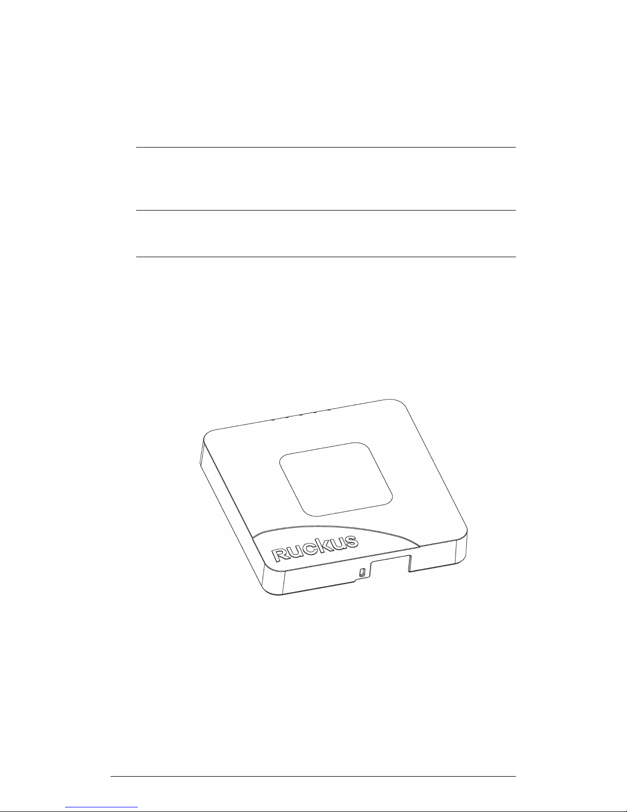
Front View Features
The following figure shows the top view of the R600. For a description of the front panel
LEDs, refer to the table below.
Introduction
ZoneFlex Indoor Access Point Release 104.0 User Guide
57
Page 58

Introduction
Getting to Know the AP Features
Figure 31: R600 top view
Table 29: R600 front panel LEDs
DescriptionLED
PWR
DIR
AIR
• Off: Off.
• Red: Boot up in process.
• Flashing Green: No routable IP address
• Green: On.
• Off: The AP is not being managed by a
controller (standalone mode).
• Green: The AP is being managed by a
controller.
• Slow flashing green (one flash every two
seconds): The AP is being managed by
a controller, but is currently unable to
communicate with the controller.
• Fast flashing green (two flashes every
second): The AP is being managed by
a controller and is currently receiving
configuration settings (provisioning) or
an image update.
• Off: The AP is operating in standalone
mode or operating as a root AP (RAP)
or a non-mesh AP.
• Green: The AP is functioning as a Mesh
AP (MAP), and the wireless signal to its
uplink AP is good.
• Fast flashing green (two flashes every
second): The AP is functioning as a
Mesh AP (MAP), and the wireless signal
to its uplink AP is fair.
• Slow flashing green (one flash every two
seconds): Mesh networking is enabled,
but the AP is still searching for a mesh
uplink.
2.4G
58
• Off: The WLAN service is down.
• Green: The WLAN is up and at least
one client is associated.
• Amber: The WLAN is up. No clients are
associated.
ZoneFlex Indoor Access Point Release 104.0 User Guide
Page 59
Introduction
Getting to Know the AP Features
DescriptionLED
5G
• Off: The WLAN service is down.
• Amber: The WLAN is up, but no clients
or downlink MAPs are
associated/connected.
• Green: The WLAN is up and at least
one client is associated. No downlink
MAPs are connected.
• Slow flashing green (one flash every two
seconds): The WLAN is up and at least
one downlink MAP is connected. No
clients are associated.
• Fast flashing green (two flashes every
second): The WLAN is up, at least one
downlink MAP is connected, and at
least one client is associated.
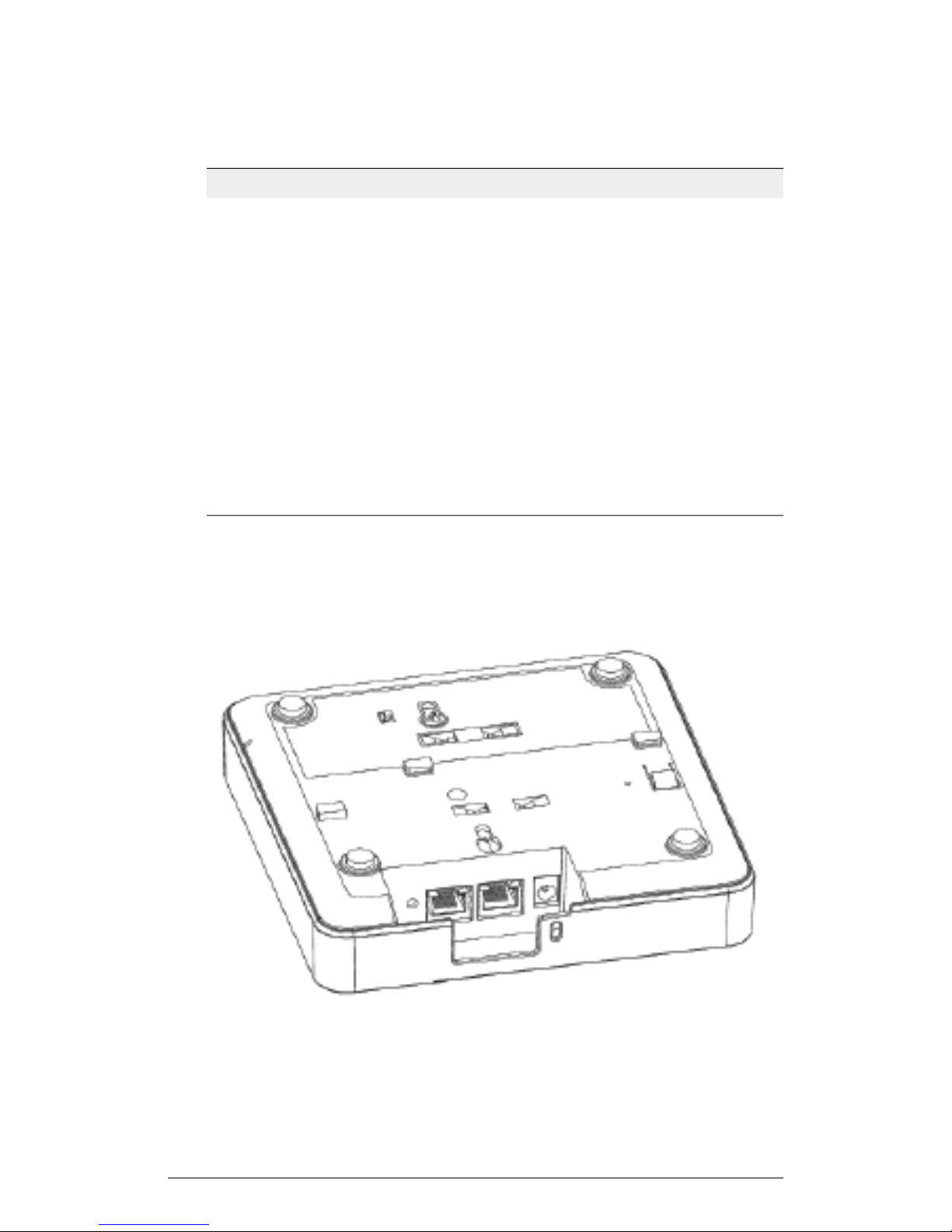
Rear Panel
The rear panel of the R600 includes one 10/100/1000 PoE Ethernet port, 10/100/1000
Ethernet port, power socket and reset button. See the table below for a description of
each rear panel part.
ZoneFlex Indoor Access Point Release 104.0 User Guide
59
Page 60
Introduction
Getting to Know the AP Features
Figure 32: R600 rear panel
Table 30: R600 Rear panel element descriptions
DescriptionLabel
RESET Button
Pressing, and then quickly releasing this
button reboots the AP. Pressing and
holding it for six seconds resets the AP to
factory default settings.
NOTE Resetting the AP to factory default
settings erases all settings that you
configured previously.
PoE Port
One RJ-45 port for a 10/100/1000 PoE
(Power over Ethernet, 802.3af/at)
connection. (The R500 is a Class 3 device.)
Ethernet Port
One RJ-45 port for a 10/100/1000
connection.
12VDC
Connect the power adapter (12
VDC/1.25A) to this socket. Power can also
be supplied via the 10/100/1000 PoE port.
Ethernet Port LEDs
Table 31: Behavior of Ethernet port LEDs on the R500
DescriptionLED
Not connectedOff
Connected to 10Mbps deviceAmber + Green
Connected to 100Mbps deviceAmber
Connected to 1000Mbps deviceGreen
WARNING! For units using Power over Ethernet (PoE). These products and all
interconnected equipment must be installed indoors within the same building, including
the associated LAN connections, as defined by Environment A of the IEEE 802.3af
Standard.
60
ZoneFlex Indoor Access Point Release 104.0 User Guide
Page 61
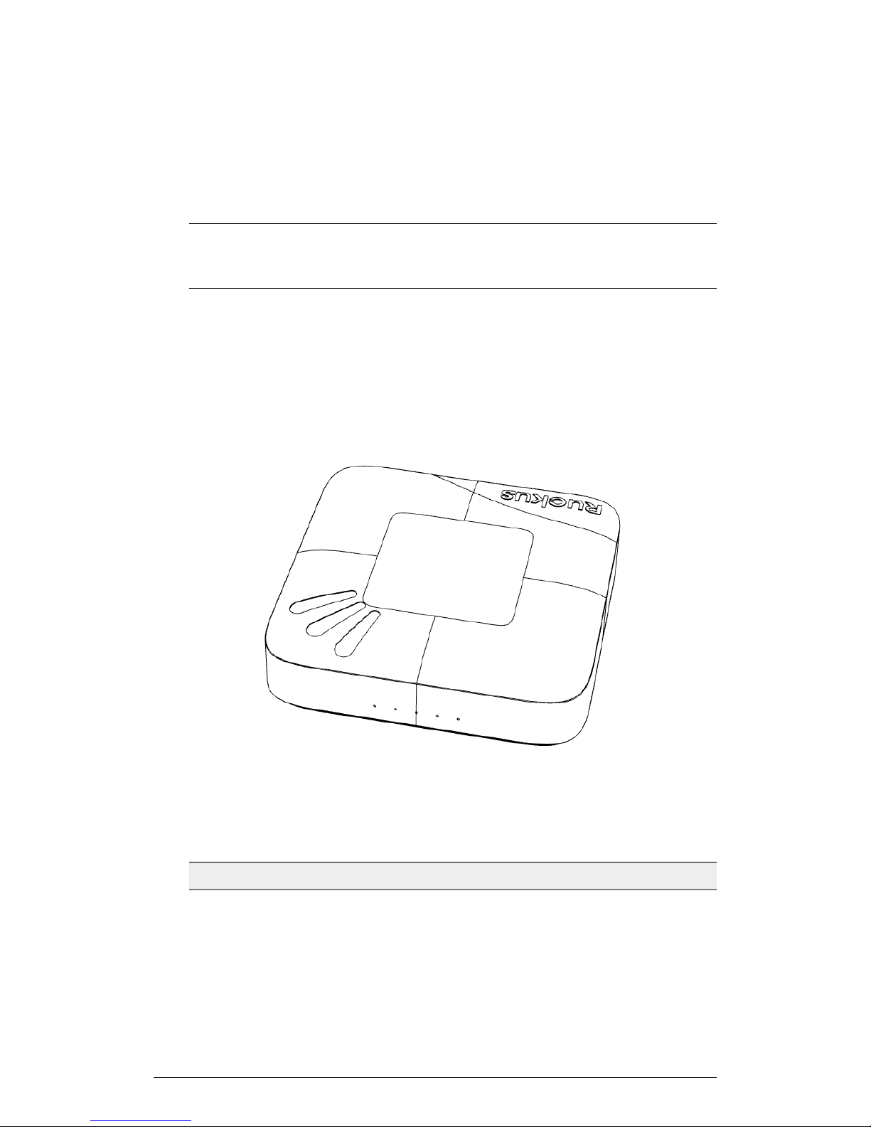
Getting to Know the AP Features
ZoneFlex R700
The R700 is a high-capacity, high-performance, three-stream, 802.11ac dual-band AP
with adaptive antenna technology for carriers and enterprises.
NOTE The R700 AP requires a minimum of AP base image 100.0.0 and later to operate,
or SCG 2.5.1 and later, vSZ 3.0 and later, SmartZone software 3.2 and later, or ZD 9.7.1
and later to operate.
The R500 includes five LEDs on its front panel and buttons and connectors on its rear
panel.
Front View Features
The following figure shows the top view of the R700. For a description of the front panel
LEDs, refer to the table below.
Introduction
Figure 33: R700 top view
Table 32: R700 front panel LEDs
PWR
ZoneFlex Indoor Access Point Release 104.0 User Guide
DescriptionLED
• Off: Off.
• Red: Boot up in process.
• Flashing Green: No routable IP address
• Green: On.
61
Page 62

Introduction
Getting to Know the AP Features
DescriptionLED
DIR
AIR
• Off: The AP is not being managed by a
controller (standalone mode).
• Green: The AP is being managed by a
controller.
• Slow flashing green (one flash every two
seconds): The AP is being managed by
a controller, but is currently unable to
communicate with the controller.
• Fast flashing green (two flashes every
second): The AP is being managed by
a controller and is currently receiving
configuration settings (provisioning) or
an image update.
• Off: The AP is operating in standalone
mode or operating as a root AP (RAP)
or a non-mesh AP.
• Green: The AP is functioning as a Mesh
AP (MAP), and the wireless signal to its
uplink AP is good.
• Fast flashing green (two flashes every
second): The AP is functioning as a
Mesh AP (MAP), and the wireless signal
to its uplink AP is fair.
• Slow flashing green (one flash every two
seconds): Mesh networking is enabled,
but the AP is still searching for a mesh
uplink.
2.4G
62
• Off: The WLAN service is down.
• Green: The WLAN is up and at least
one client is associated.
• Amber: The WLAN is up. No clients are
associated.
ZoneFlex Indoor Access Point Release 104.0 User Guide
Page 63
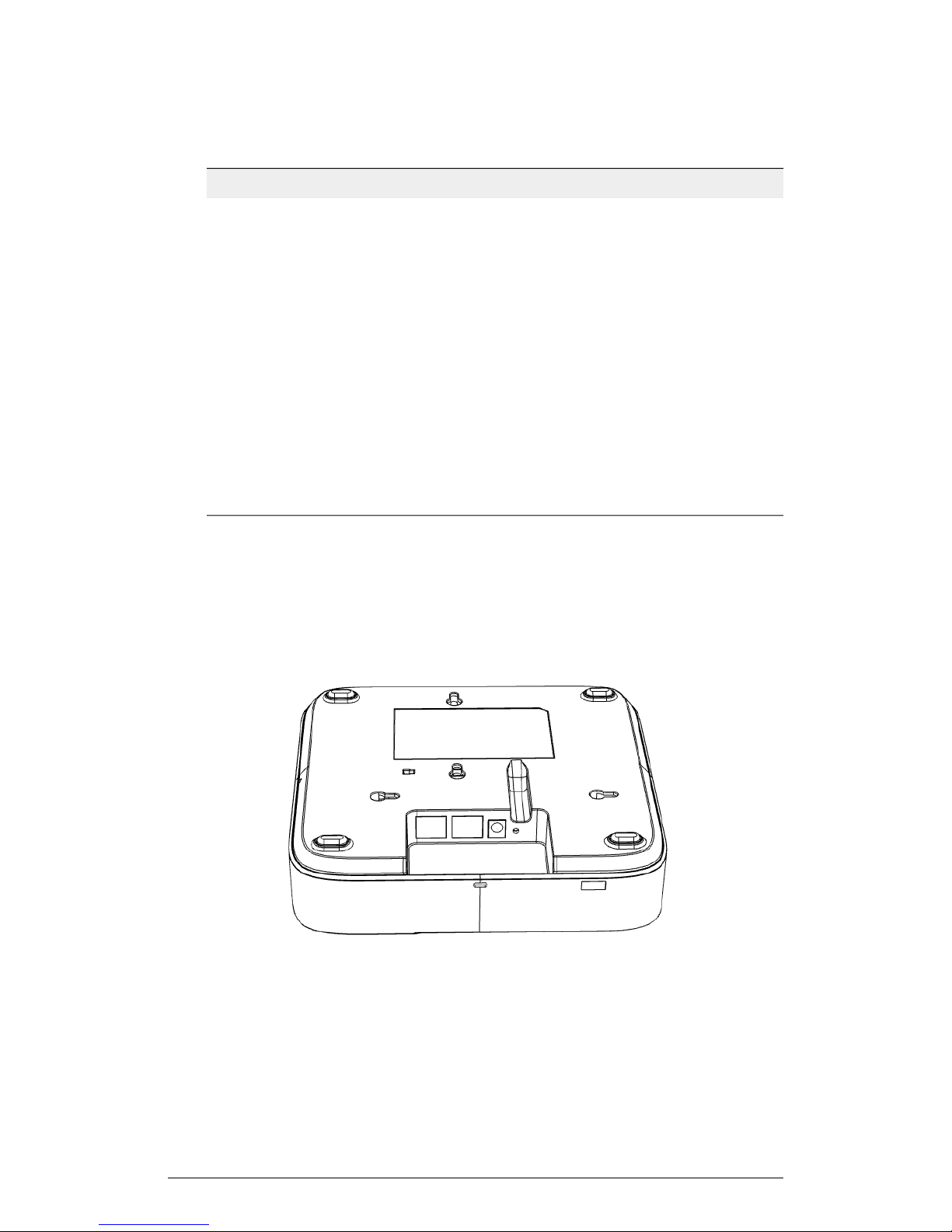
Introduction
Getting to Know the AP Features
DescriptionLED
5G
• Off: The WLAN service is down.
• Amber: The WLAN is up, but no clients
or downlink MAPs are
associated/connected.
• Green: The WLAN is up and at least
one client is associated. No downlink
MAPs are connected.
• Slow flashing green (one flash every two
seconds): The WLAN is up and at least
one downlink MAP is connected. No
clients are associated.
• Fast flashing green (two flashes every
second): The WLAN is up, at least one
downlink MAP is connected, and at
least one client is associated.
Rear Panel
The rear panel of the R700 includes one 10/100/1000 PoE Ethernet port, 10/100/1000
Ethernet port, power socket and reset button. See the table below for a description of
each rear panel part.
ZoneFlex Indoor Access Point Release 104.0 User Guide
63
Page 64
Introduction
Getting to Know the AP Features
Figure 34: R700 rear panel
Table 33: R700 Rear panel element descriptions
DescriptionLabel
ETHERNET + PoE Port
One RJ-45 port for a 10/100/1000 PoE
(Power over Ethernet, 802.3af/at)
connection. (The R700 is a Class 3 device.)
ETHERNET Port
One RJ-45 port for a 10/100/1000
connection.
12V 1.5A Power Socket
Connect the power adapter (12
VDC/1.25A) to this socket. Power can also
be supplied via the ETHERNET + PoE port.
RESET Button
Pressing, and then quickly releasing this
internal button reboots the AP. Pressing
and holding it for six seconds resets the
AP to factory default settings.
NOTE Resetting the AP to factory default
settings erases all settings that you
configured previously.
Ethernet Port LEDs
Table 34: Behavior of Ethernet port LEDs on the R700
DescriptionLED
Not connectedOff
Connected to 10Mbps deviceAmber + Green
Connected to 100Mbps deviceAmber
Connected to 1000Mbps deviceGreen
WARNING! For units using Power over Ethernet (PoE). These products and all
interconnected equipment must be installed indoors within the same building, including
the associated LAN connections, as defined by Environment A of the IEEE 802.3af
Standard.
64
ZoneFlex Indoor Access Point Release 104.0 User Guide
Page 65
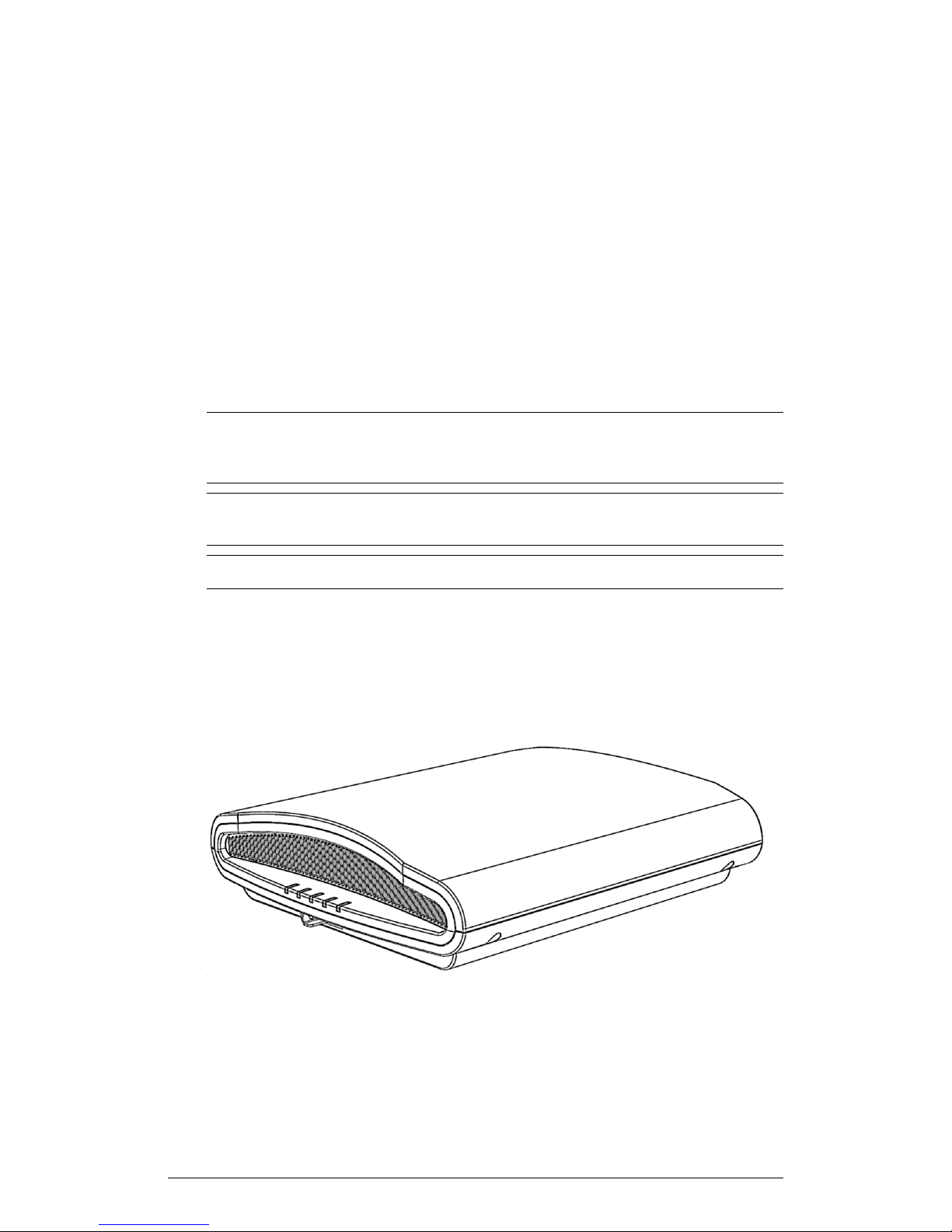
Getting to Know the AP Features
ZoneFlex R710
The R710 is a high-capacity, high-performance, four-stream, dual-band 802.11ac Wave
2 AP with adaptive antenna technology for carriers and enterprises.
The R710 has a USB port on its bottom panel. The USB port is intended for low-power
devices such as BLE (Bluetooth low energy) beacons. The maximum power that the
USB port can supply is 0.5W. Refer to Appendix A: AP Support for Bluetooth Low Energy
Devices on page 148 for more information.
The R710 can use the link aggregation control protocol (LACP) to control the bonding
of two 1Gbps physical Ethernet ports together to form a single logical channel. Refer to
Appendix B: Configuring Link Aggregation (LACP) for AP Backhaul on page 149 for
instructions on bonding the two Ethernet ports using LACP.
NOTE The 100.x AP base images support standalone mode and FlexMaster (FM)
WLAN manager operation. The SmartZone software-compatible images only support
SCG, SZ and vSZ controllers. The ZD-compatible images only support ZD controllers.
NOTE The R710 AP requires a minimum of AP base image 100.2.0 and later to operate,
or SmartZone software 3.1.1 and later, or ZD 9.12 and later to operate.
Introduction
NOTE The R710 is not supported by the ZoneDirector 1100.
The R710 includes five LEDs on its front panel, and buttons and connectors on its bottom
panel.
Front View Features
The following figure shows the top view of the R710. For a description of the front panel
LEDs, refer to the table below.
ZoneFlex Indoor Access Point Release 104.0 User Guide
65
Page 66

Introduction
Getting to Know the AP Features
Figure 35: R710 front view
Table 35: R710 front panel LEDs
DescriptionLED
PWR
CTL
AIR
• Off: Off.
• Red: Boot up in process.
• Flashing Green: No routable IP address
• Green: On.
• Off: The AP is not being managed by a
Ruckus Wireless controller (standalone
mode).
• Green: The AP is being managed by a
Ruckus Wireless controller.
• Slow flashing green (one flash every two
seconds): The AP is being managed by
a Ruckus Wireless controller, but is
currently unable to communicate with
controller.
• Fast flashing green (two flashes every
second): The AP is being managed by
a Ruckus Wireless controller and is
currently receiving configuration settings
(provisioning) or an image update.
• Off: The AP is operating in standalone
mode or operating as a root AP (RAP)
or a non-mesh AP.
• Green: The AP is functioning as a Mesh
AP (MAP), and the wireless signal to its
uplink AP is good.
• Fast flashing green (two flashes every
second): The AP is functioning as a
Mesh AP (MAP), and the wireless signal
to its uplink AP is fair.
• Slow flashing green (one flash every two
seconds): Mesh networking is enabled,
but the AP is still searching for a mesh
uplink.
66
ZoneFlex Indoor Access Point Release 104.0 User Guide
Page 67

Introduction
Getting to Know the AP Features
DescriptionLED
2.4G
5G
• Off: The WLAN service is down.
• Green: The WLAN is up and at least
one client is associated.
• Amber: The WLAN is up. No clients are
associated.
• Off: The WLAN service is down.
• Amber: The WLAN is up, but no clients
or downlink MAPs are
associated/connected.
• Green: The WLAN is up and at least
one client is associated. No downlink
MAPs are connected.
• Slow flashing green (one flash every two
seconds): The WLAN is up and at least
one downlink MAP is connected. No
clients are associated.
• Fast flashing green (two flashes every
second): The WLAN is up, at least one
downlink MAP is connected, and at
least one client is associated.
Bottom Panel
The bottom panel of the R710 includes the following:
• one 10/100/1000 PoE In Ethernet port
• one 10/100/1000 Ethernet port
• one 12VDC 2A power socket
• one reset button
• one USB port
ZoneFlex Indoor Access Point Release 104.0 User Guide
67
Page 68
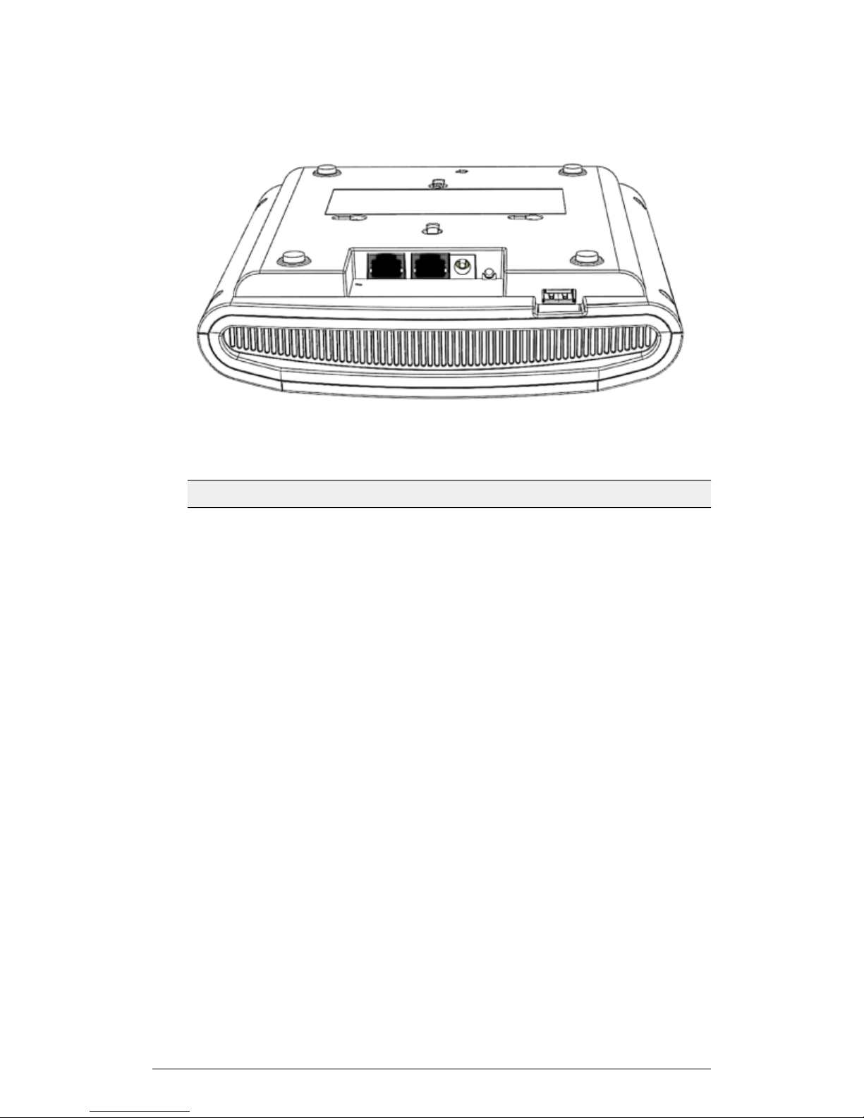
Introduction
Getting to Know the AP Features
Figure 36: R710 bottom panel
Table 36: R710 Rear panel elements
DescriptionLabel
RJ-45 port for a 10/100/1000 connection.Ethernet (eth1) Port
68
ZoneFlex Indoor Access Point Release 104.0 User Guide
Page 69

Introduction
Getting to Know the AP Features
DescriptionLabel
Ethernet + PoE (eth0) Port
RJ-45 port for a 10/100/1000 with PoE in.
NOTE The R710 can be powered by a
802.3at-compliant (25.5W) Power over
Ethernet (PoE) switch or PoE injector.
--OR-- an 802.3af-compliant PoE switch
or PoE injector.
CAUTION! The AP can operate off of
802.3af power, but the feature set is
reduced: the USB port is disabled, the
non-PoE (eth1) Ethernet port is disabled,
and the 2.4 GHz radio is reduced to two
transmit streams (2x4 MIMO) with
aggregate transmit power up to 22dBm
(subject to country limits).
WARNING! For units using Power over
Ethernet (PoE). These products and all
interconnected equipment must be installed
indoors within the same building, including
the associated LAN connections, as
defined by Environment A of the IEEE
802.3af Standard.
12V 2A Power Socket
RESET Button
Connect a customer-ordered Ruckus
Wireless 12VDC 902-1169-xx00 AC power
adapter (sold separately). When powered
by the 902-1169-xx00 power adapter, the
R710 supports a full feature set.
NOTE Power can alternately be supplied
via the Ethernet + PoE port.
Pressing, and then quickly releasing this
internal button reboots the AP. Pressing
and holding it for six seconds resets the
AP to factory default settings.
NOTE Resetting the AP to factory default
settings erases all settings that you
configured previously.
ZoneFlex Indoor Access Point Release 104.0 User Guide
69
Page 70
Introduction
Getting to Know the AP Features
DescriptionLabel
USB Port
The R710 can have a low-power (0.5W or
less) customer-supplied USB device
plugged in. The USB device is hidden after
the R710 is attached to its mounting base.
Ethernet Port LEDs
Table 37: Behavior of Ethernet port LEDs on the R710
DescriptionLED
Not connectedOff
Connected to 10Mbps deviceAmber + Green
Connected to 100Mbps deviceAmber
Connected to 1000Mbps deviceGreen
WARNING! For units using Power over Ethernet (PoE). These products and all
interconnected equipment must be installed indoors within the same building, including
the associated LAN connections, as defined by Environment A of the IEEE 802.3af
Standard.
70
ZoneFlex Indoor Access Point Release 104.0 User Guide
Page 71

Page 72

72
Installation
Before You Begin
Before starting with the installation, make sure that you have the required items for the
installation ready. In addition, verify that the wireless stations on the network have the
required components for wireless communication with the AP.
This section describes the pre-installation tasks that you need to perform.
Performing a Site Survey
Before installing the AP, perform a site survey to determine the optimal AP placement
for maximum range, coverage, and network performance.
Ruckus Wireless Support can supply Site Survey best practices information. When
performing a site survey, consider the following factors:
• Data rates: Range is generally inversely proportional to data rates. The maximum
radio range is achieved at the lowest workable data rate. Higher data rates are
generally achieved at closer distances.
• Antenna type and placement: Proper antenna configuration is a critical factor in
maximizing radio range. As a general rule, radio range is increased by mounting the
antennas higher off of the ground.
• Physical environment: Clear or open areas provide better radio range than crowded
or filled areas. The less cluttered the operating environment, the greater the wireless
range.
• Obstructions, building materials, and sources of interference: Physical obstructions,
such as concrete pillars, steel beams and filing cabinets can block or hinder wireless
communication. Avoid installing the AP in a location where there is an obstruction
between sending and receiving devices. A number of machines and electronic devices
that emit radio waves – cranes, wireless phones, microwave ovens, and satellite
dishes – interfere with and block wireless signals. Building materials used in
construction also influence radio signal penetration. For example, drywall construction
permits greater range than concrete blocks.
2
For more AP placement guidelines, refer to Determining the Optimal Mounting Location
and Orientation on page 72.
Determining the Optimal Mounting Location and Orientation
The location and orientation that you choose for the AP play a critical role in the
performance of your wireless network.
In general, Ruckus Wireless recommends installing the AP away from obstructions and
sources of interference and ensuring that the top of the AP is pointing in the general
direction of its wireless clients.
ZoneFlex Indoor Access Point Release 104.0 User Guide
72
Page 73
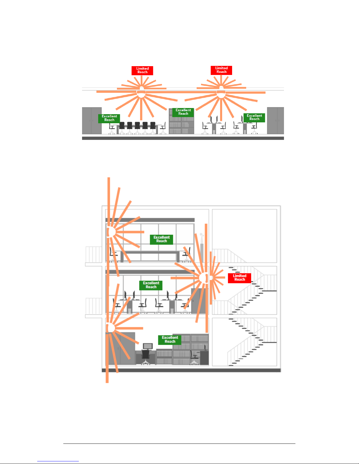
Figure 37: Recommended ceiling mounting orientation
When wall mounted, the APs should be staggered to maximize coverage.
Installation
Before You Begin
ZoneFlex Indoor Access Point Release 104.0 User Guide
73
Page 74
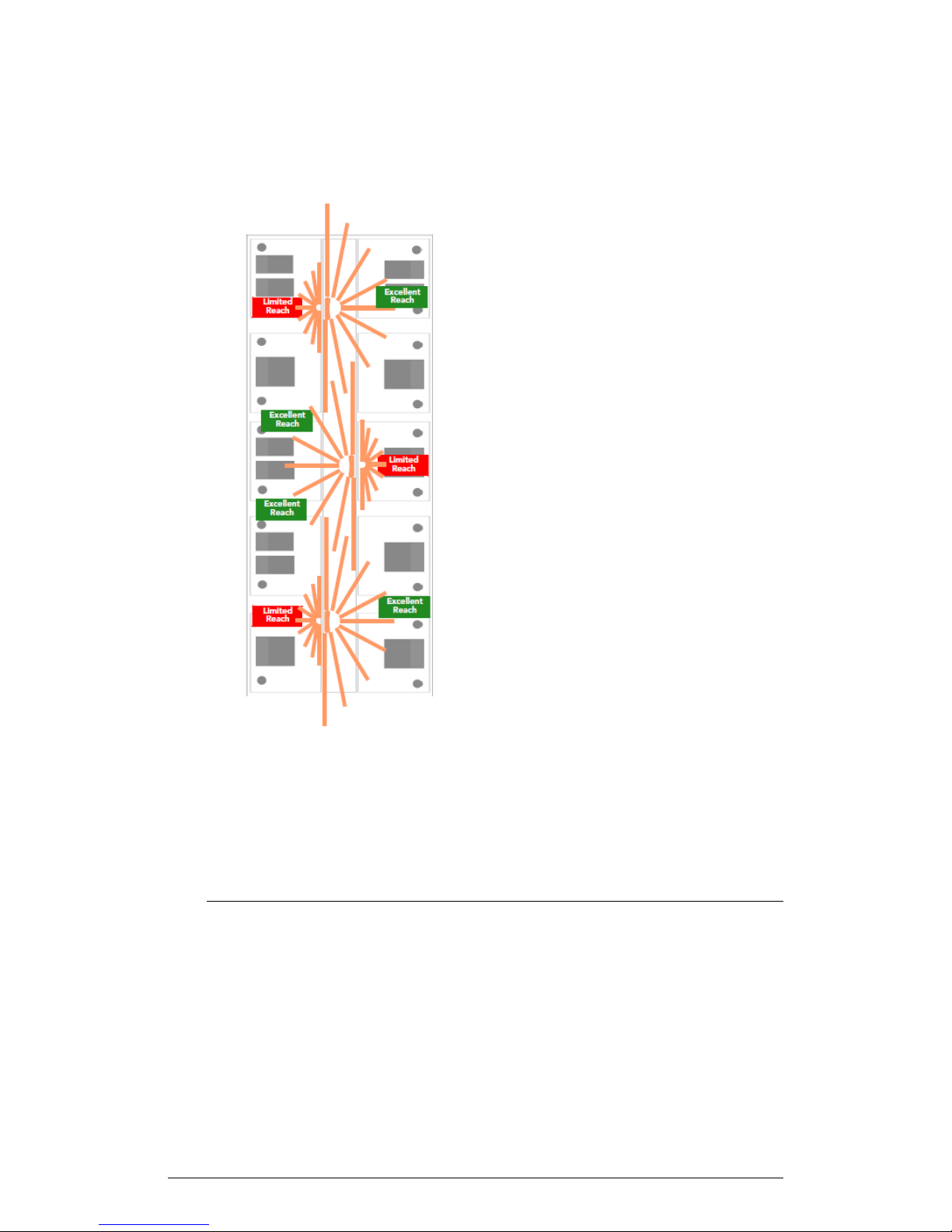
Installation
Step 1: Preconfiguring the AP
Figure 38: Recommended wall mounting orientation
Figure 39: Recommended wall mounting in a corridor (top view)
Step 1: Preconfiguring the AP
Preconfigure the AP for standalone operation, for management by FlexMaster, or for
management by a Ruckus Wireless ZoneDirector or SmartZone controller.
NOTE The 100.0.0 and later APs are shipped from the factory with an AP base image,
which supports standalone and FlexMaster-managed operation, and which does not
support SmartZone or ZoneDirector controller operation. After you have configured the
AP with the base image as described in the following sections, the AP automatically
goes out and finds any operator-defined controllers. If the AP finds a controller that is
configured to automatically recognize the AP, then the controller downloads the
74
ZoneFlex Indoor Access Point Release 104.0 User Guide
Page 75

Installation
Step 1: Preconfiguring the AP
controller-specific AP firmware. If the AP does not find a controller, then it retains its
base image AP firmware.
NOTE If the AP has been configured with SmartZone or ZoneDirector controller-specific
AP firmware, then it retains that image after a factory reset. To replace a controller-specific
AP image with the standalone AP firmware, download the specific AP image from
https://support.ruckuswireless.com/#products_grid and perform an upgrade from the
AP web interface.
The procedure for completing the AP's basic configuration depends on whether you
want it to be managed by SmartZone, ZoneDirector, FlexMaster, or to operate as a
standalone AP. Refer to the section that is relevant to your deployment:
• Configuring the AP for Management by a SmartZone Controller on page 75
• Configuring the AP for Management by ZoneDirector on page 75
• Configuring the AP for Standalone Operation or for Management by FM on page 76
Configuring the AP for Management by a SmartZone Controller
When your Ruckus Wireless network is managed by a SmartZone controller, you can
manage APs using the controller rather than individually logging into each AP's web
interface.
If a SmartZone controller is installed on the network, follow the instructions in the
SmartZone documentation to configure the controller, and then connect the AP to your
network. The AP automatically finds the controller and then downloads the
SmartZone-compatible AP firmware image from the controller.
NOTE The AP must have some way of obtaining an IP address (IPv4 DHCP or IPv6
Auto Configuration).
Configuring the AP for Management by ZoneDirector
When your Ruckus Wireless network is managed by a ZoneDirector controller, you can
manage APs using the controller rather than individually logging into each AP's web
interface.
If ZoneDirector is installed on the network, then follow the instructions in the ZoneDirector
User Guide and connect the AP to your network. The AP finds the ZD, and then
downloads the ZD-compatible AP image from the controller.
NOTE The AP must have some way of obtaining an IP address (IPv4 DHCP or IPv6
Auto Configuration).
ZoneFlex Indoor Access Point Release 104.0 User Guide
75
Page 76

Installation
Step 1: Preconfiguring the AP
Configuring the AP for Standalone Operation or for
Management by FM
This section describes the steps you need to complete to set up the AP in standalone
mode or to be managed by a Ruckus Wireless FlexMaster server, if you have one installed
on the network.
Collect the Required Materials
The following materials are required to be supplied by the user for preconfiguring the
AP.
Before starting with the configuration task, make sure that you have the following
requirements ready:
• An administrative computer with a web browser, Ethernet port and a wireless network
card installed.
• Two Ethernet cables (Cat5e or better for PoE in)
• (Optional) An AC power adapter (sold separately), --or-- (Optional) an 802.3af or
802.3at -compliant Power over Ethernet (PoE) switch or PoE injector.
Prepare the Administrative Computer
Prepare the admin computer for preconfiguring the AP.
NOTE The following procedure uses Windows 7 as an example. The steps required
for modifying your computer's IP address settings may be different if using another
operating system.
1. On your Windows 7 computer, open the Network Connections control panel:
Click Start > Control Panel > Network and Internet > Network and Sharing Center
> Change Adapter Settings.
2. When the Network Connections window appears, right-click the icon for Local
Area Connection, and then click Properties.
NOTE Make sure that you configure the Local Area Connection Properties, not
the Wireless Network Connection Properties.
3. When the Local Area Connection Properties dialog box appears, select Internet
Protocol Version 4 (TCP/IPv4) from the scrolling list, and then click Properties.
The Internet Protocol (TCP/IP) Properties dialog box appears.
4. Write down all of the currently active network settings. You will need this information
later when you restore your computer to its current network configuration.
5. Click Use the following IP address, and then configure the IP address settings with
the values listed in the following table. For a sample configuration, refer to the figure
below.
76
ZoneFlex Indoor Access Point Release 104.0 User Guide
Page 77
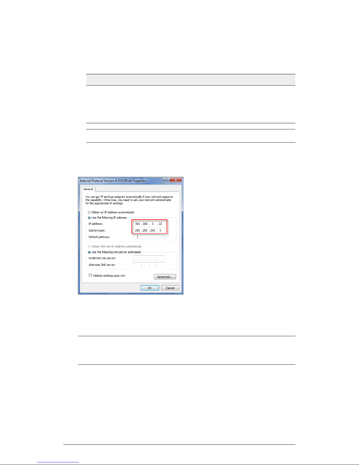
Table 38: Configure your computer's IP address settings
ValueSetting
Installation
Step 1: Preconfiguring the AP
IP address
192.168.0.22 (or any address in the 192.168.0.x
network—with the exception of 192.168.0.1, which
is the default IP address assigned to the AP)
255.255.255.0Subnet mask
NOTE You can leave the Default Gateway and DNS server fields blank.
6. Click OK to save your changes and close the TCP/IP Properties dialog box.
7. Click OK again to close the Local Area Connection Properties dialog box.
Windows saves the IP address settings that you have configured.
Figure 40: Sample configuration in the Internet Protocol (TCP/IP) Properties dialog box
Connect the AP to the Administrative Computer
Connect the AP to the admin computer using an Ethernet cable.
CAUTION! Do NOT connect the AP to your live network at this point. If you connect
it to a live network with an active DHCP server, the AP acquires a new IP address from
DHCP and you will be unable to access it via the default IP address (192.168.0.1).
1. Connect one end of an Ethernet cable to an Ethernet port on the AP, and then connect
the other end to the administrative computer's Ethernet port.
2. Provide power to the AP using either an AC adapter or a PoE injector or switch.
ZoneFlex Indoor Access Point Release 104.0 User Guide
77
Page 78
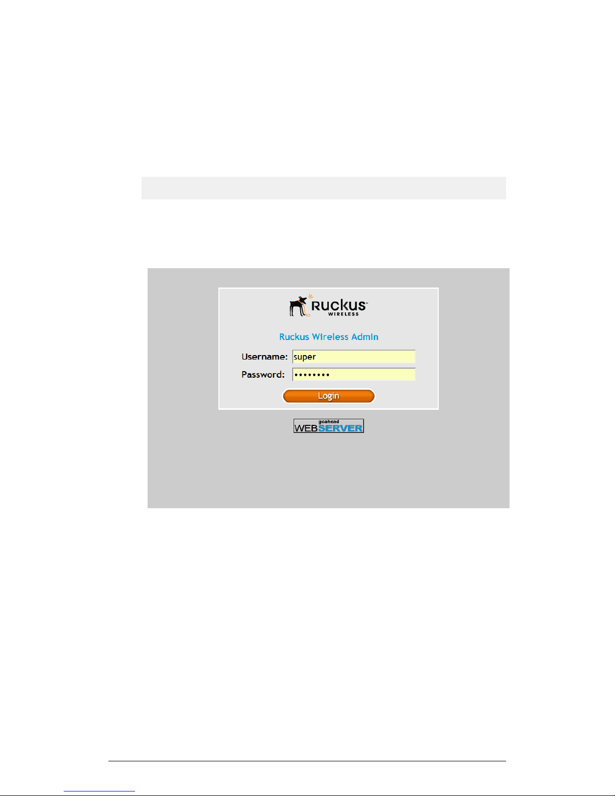
Installation
Step 1: Preconfiguring the AP
Log Into the AP's Web Interface
Log into the AP to preconfigure the AP for standalone/FlexMaster operation.
1. On the administrative computer, open a web browser window.
2. In the address or location bar, type the following address:
https://192.168.0.1
3. Press Enter on the keyboard to connect to the AP's web interface. A security alert
message appears.
4. Click Yes or OK or Proceed anyway (depending on the browser) to continue. The
AP's login page appears.
Figure 41: The Ruckus Wireless AP login page
5. In User name, type super.
6. In Password, type sp-admin.
7. Click Login. The web interface appears, displaying the Status > Device page.
8. Continue to Configure the Wireless Settings on page 79.
78
ZoneFlex Indoor Access Point Release 104.0 User Guide
Page 79
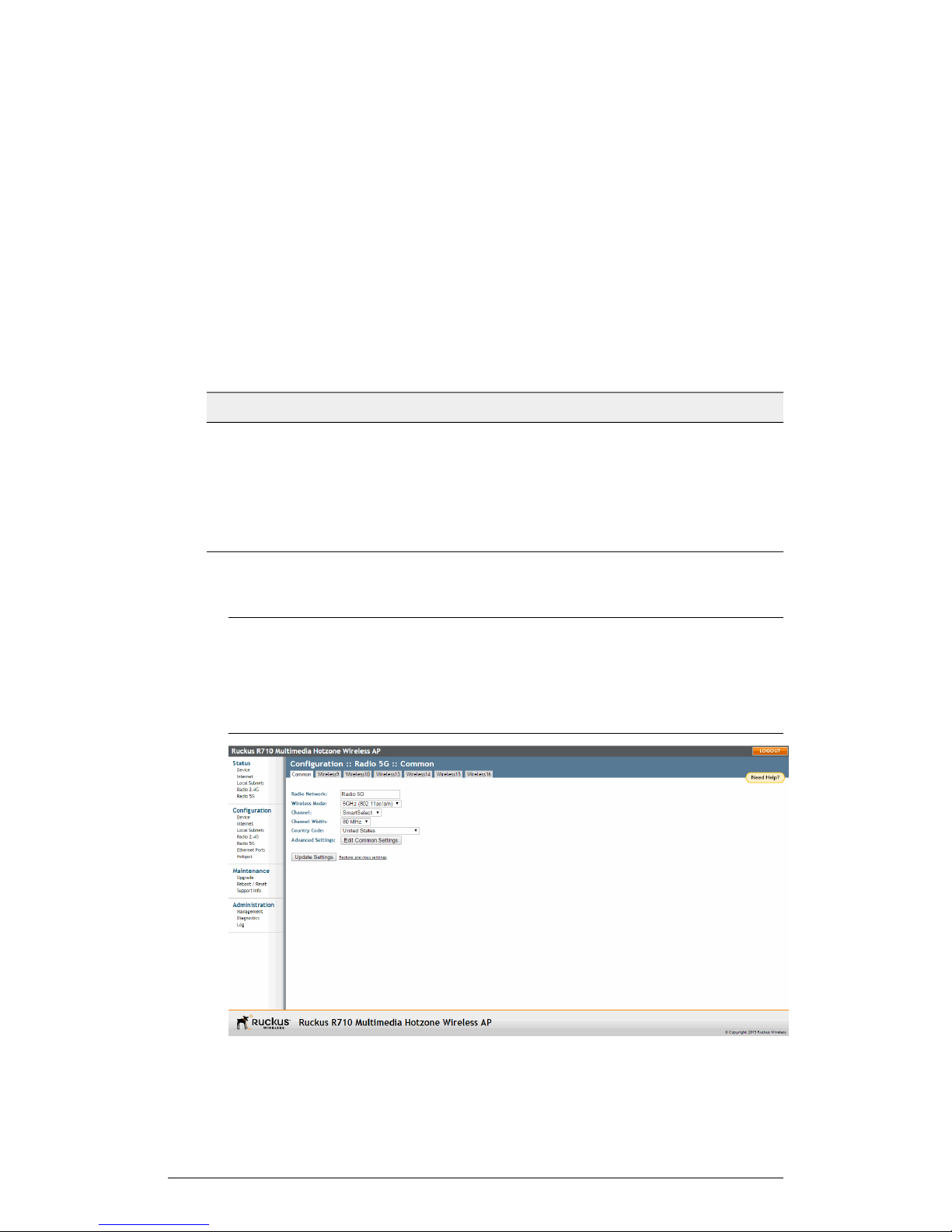
Installation
Step 1: Preconfiguring the AP
Configure the Wireless Settings
To complete this step, configure the settings on the Common tab and at least one
Wireless # (WLAN Number) tab.
Configuring Common Wireless Settings
These are the essential wireless settings that enable wireless devices on the network to
associate with the AP.
For your reference, the default wireless settings for the WLANs are listed in the following
table.
Table 39: Default WLAN wireless settings
Default ValueSetting
SSID (network name)
Wireless 1 to Wireless 8 (2.4 GHz Radio)
Wireless 9 to Wireless 16 (5 GHz Radio only available on dual radio APs)
Disabled on all WLANsEncryption (security)
192.168.0.1Default management IP address
1. On the left menu of the web interface, click Configuration > Wireless (Radio 2.4G
or Radio 5G on dual-band APs). The Configuration > Common page appears.
NOTE For dual-band APs (7055, 7372, 7982, H500, R300, R310, R500, R510,
R600, R700 and R710), the two radios (2.4GHz and 5GHz) need to be configured
separately on the web interface. To configure the common wireless settings, click
Configuration > Radio 2.4G or Configuration > Radio 5G. The rest of the
configuration procedures are the same as for single-band models.
ZoneFlex Indoor Access Point Release 104.0 User Guide
79
Page 80
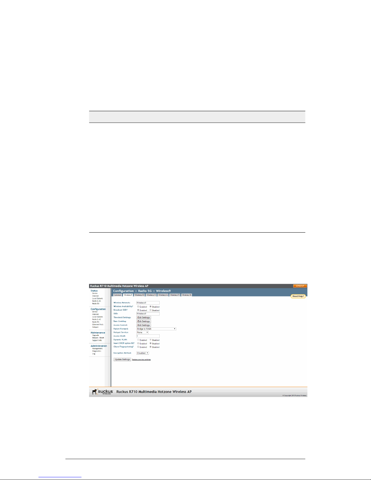
Installation
Step 1: Preconfiguring the AP
Figure 42: The Configuration > Radio 5G > Common tab
2. Verify that the common wireless settings are configured as listed in the following
table.
Table 40: Common wireless configuration
Recommended ValueSetting
SmartSelect.Channel
Country Code
If you purchased the AP in the United States, this
value is fixed to United States at the factory and is
not user configurable. If you purchased the AP
outside the United States, verify that the value is set
to your country or region. Selecting the correct
country code ensures that the AP uses only the radio
channels allowed in your country or region. Note for
dual-band AP users: The two radios on dual-band
APs are always configured with the same country
code setting. If you change the country code for
Radio 1, for example, the same change is
automatically applied to Radio 2.
3. If you made any changes to the Common tab, click Update Settings.
4. Continue with "Configuring Wireless # (WLAN number) Settings" below.
Configuring Wireless # (WLAN number) Settings
1. Click one of the Wireless # (WLAN number) tabs.
80
ZoneFlex Indoor Access Point Release 104.0 User Guide
Page 81
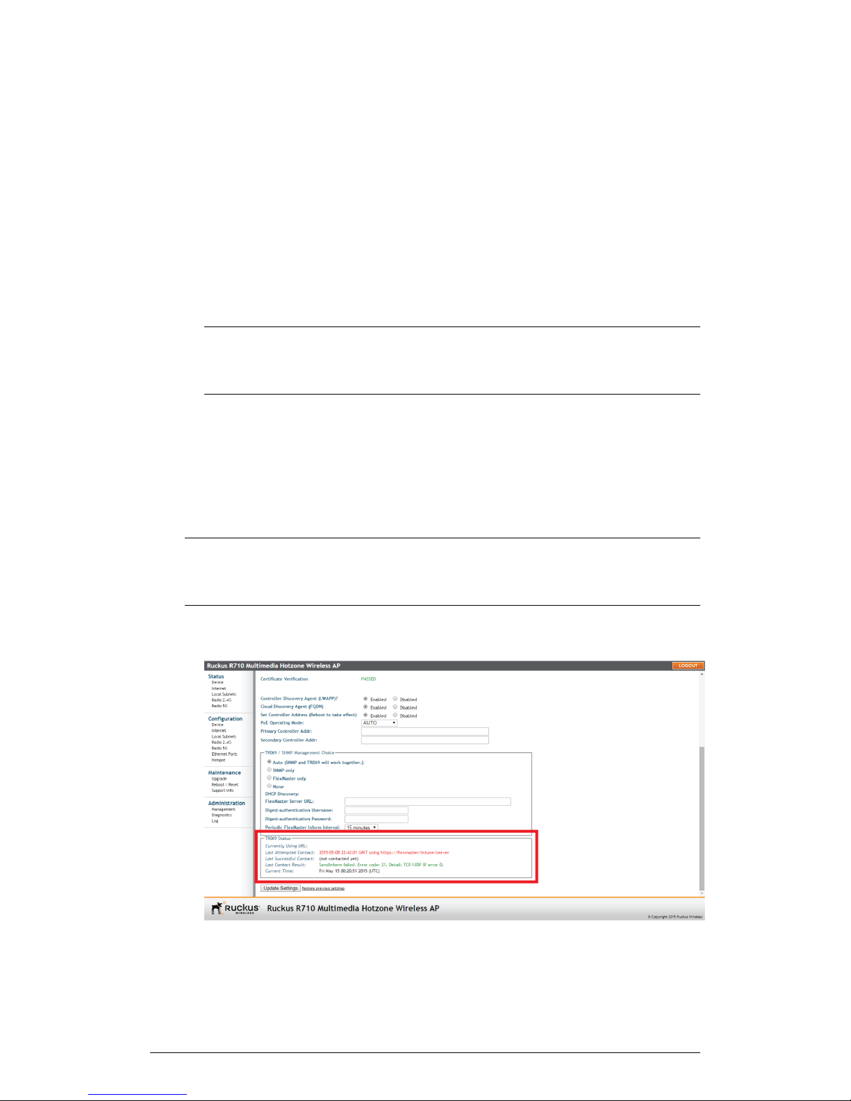
Installation
Step 1: Preconfiguring the AP
Figure 43: The Configuration > Radio 5G > Wireless 9 tab
2. In Wireless Availability, click Enabled.
3. In Broadcast SSID, click Enabled.
4. Clear the SSID box, and then type a unique and descriptive name that you want to
call this wireless network.
For example, you can type Ruckus Wireless AP. This SSID is the name that
helps users identify this wireless network in their wireless network connection
application.
NOTE You may also configure other wireless settings on this and other Wireless #
tabs (in addition to the settings described above), although it is not necessary for
completing the AP installation.
5. Click Update Settings.
You have completed configuring the basic wireless settings of the AP.
(Optional) Setting the FlexMaster Server Address
When you have a FlexMaster server installed on the network and you intend to use
FlexMaster to manage the AP, you can set the FlexMaster server address at this point.
Before starting this procedure, make sure you obtain the correct FlexMaster server URL.
NOTE In addition to setting the FlexMaster server URL manually on the AP, you can
also use DHCP Option 43 or DNS to point the AP to the FlexMaster server. For more
information, refer to the FlexMaster User Guide.
1. On the menu, click Administration > Management.
2. Scroll down the page to the TR069 / SNMP Management Choice section.
ZoneFlex Indoor Access Point Release 104.0 User Guide
81
Page 82

Installation
Step 1: Preconfiguring the AP
Figure 44: Type the FlexMaster server URL
3. Verify that the Auto option is selected.
4. In FlexMaster Server URL, type the URL of the FlexMaster server on the network.
You can use either http or https to connect to the URL and include either the host
name or IP address of the FlexMaster server in the URL. The following are examples
of valid FlexMaster server URLs:
• http://flexmaster/intune/server
• https://flexmaster/intune/server
• http://192.168.20.1/intune/server
• https://192.168.20.1/intune/server
5. Click Update Settings to save your changes.
You have completed setting the FlexMaster server address on the AP.
NOTE Instructions on how to verify that the AP and FlexMaster can communicate with
each other are provided in Check the TR069 Status (FlexMaster Management Only) on
page 84.
Disconnecting the AP from the Administrative Computer
Once preconfiguration is complete, disconnect the AP from the admin computer.
1. Disconnect the AP from the power source.
2. Verify that the power LED on the AP is off.
3. Disconnect the Ethernet cable from the administrative computer's Ethernet port.
Restoring the Administrative Computer's Network Settings
(Optional)
Return your admin PC to its original configuration.
1. On your Admin computer, open the Network Connections control panel according
to how the Start menu is set up:
On Windows 7, click Start > Control Panel > Network and Internet > Network
and Sharing Center > Change Adapter Settings
2. When the Network Connections window appears, right-click the icon for Local
Area Connection, and then click Properties.
3. When the Local Area Connection Properties dialog box appears, select Internet
Protocol Version 4 (TCP/IPv4) from the list, and then click Properties. The TCP/IPv4
Properties dialog box appears.
4. Restore the computer's network settings by typing the original IP address settings
in the TCP/IP Properties dialog box.
5. On the TCP/IP Properties dialog box, click OK to close it.
82
ZoneFlex Indoor Access Point Release 104.0 User Guide
Page 83

Step 2: Verifying AP Operation
6. Click OK again to close the Local Area Connection Properties dialog box.
You are now ready to connect the AP to your network.
Step 2: Verifying AP Operation
Before deploying the AP in your environment, Ruckus Wireless strongly recommends
that you verify that the AP is operating correctly.
To do this, connect the AP to your live network temporarily and make sure that the
network connection works and that wireless clients are able to associate with the AP
and connect to your network and the Internet.
NOTE The network and power connections that you make in this step are temporary.
Continue with the following:
• Connect the AP to the Network on page 83
• Associate a Wireless Client with the AP on page 83
• Check the LEDs on page 84
• Check the TR069 Status (FlexMaster Management Only) on page 84
• Disconnect the AP from the Network on page 84
Installation
Connect the AP to the Network
Use an Ethernet cable to connect the AP to your network.
1. Connect the Ethernet cable from a LAN (RJ-45) port on the AP to your network's
router or switch.
2. Reconnect the AP to a power source.
You have completed connecting the AP to your live network. Perform the tasks described
in the following sections to verify that the AP is operating normally.
Associate a Wireless Client with the AP
Associate to the WiFi network to verify AP operation.
1. On the administrative computer, verify that the wireless interface is enabled.
2. Connect your admin computer to the wireless network.
3. In the list of available wireless networks, click the network with the same SSID as
you configured in Configure the Wireless Settings on page 79. For example, if you
set the SSID to "Ruckus Wireless AP," click the wireless network named Ruckus
Wireless AP.
4. Click Connect.
Your wireless client connects to the wireless network.
ZoneFlex Indoor Access Point Release 104.0 User Guide
83
Page 84

Installation
Step 2: Verifying AP Operation
Check the LEDs
Perform a spot-check using the LEDs to verify that the AP is operating normally.
Refer to the following sections for information on how to check the LEDs on each Ruckus
Wireless AP model.
Single-Radio APs (7352)
If the single-radio AP is operating normally and your wireless client was able to associate
with it:
• The WLAN LED is green.
• When you do not have Ruckus Wireless ZoneDirector on the network, the DIR LED
is off. This indicates that the AP is operating in standalone mode. If there is a
ZoneDirector device on the network, then the DIR LED is green.
Dual-Radio APs (7055/7372/7982/H500/R300/R310/R500/R510/R600/R700/R710)
If the dual-radio AP is operating normally and your wireless client was able to associate
with it:
• The 2.4G or 5G LED is green.
• When you do not have a Ruckus Wireless ZoneDirector on the network, the DIR LED
is off. This indicates that the AP is operating in standalone mode. If there is a
ZoneDirector device on the network, then the DIR LED is green.
Check the TR069 Status (FlexMaster Management Only)
If you configured the AP to report to a FlexMaster server on the network, make sure you
verify that it can successfully communicate with the FlexMaster server.
You can do this by checking the TR069 status on the AP's web interface.
1. Log in to the AP's web interface.
2. Go to the Administration > Management page.
3. Scroll down to the TR069 Status section.
4. Check the value for Last Successful Contact. If it shows a date in green, this
indicates that the AP was able to successfully communicate with FlexMaster.
Disconnect the AP from the Network
Once the AP has been preconfigured, disconnect its temporary connection to prepare
for installation in its permanent mounting location.
1. Disconnect the AP from the power source.
2. Disconnect the Ethernet cable that runs to the AP's RJ45 port from your network's
router or switch.
You are now ready to deploy the AP in its permanent mounting location.
84
ZoneFlex Indoor Access Point Release 104.0 User Guide
Page 85

Step 3: Deploying the AP
Step 3: Deploying the AP
Deploy the AP to its permanent mounting location.
In this step, you place the AP in a suitable location on the network and connect it to a
power source and to your network environment. Continue with the following:
1. Choosing a Location for the AP
You can install the AP on a flat surface (for example, on a desktop or tabletop) or mount
it on a wall or ceiling.
When choosing a location for the AP, ensure that the location:
• Allows easy viewing of the LEDs and access to the connectors, if necessary.
• Is centrally located to the wireless clients that are connecting to the AP. A suitable
location might be on top of a cabinet or similar furniture to optimize wireless
connections to clients in both horizontal and vertical directions, allowing wider
coverage.
Installation
When positioning your AP, ensure that:
• It is out of direct sunlight and away from sources of heat.
• Cabling is away from power lines, fluorescent lighting fixtures, and sources of electrical
noise such as radios, transmitters and broadband amplifiers.
• There are no thick walls or metal shielding between the AP and the wireless stations.
• Water or moisture cannot enter the case of the unit.
• Air flow around the unit and through the vents in the side of the case is not restricted.
Review the recommendations in Determining the Optimal Mounting Location and
Orientation on page 72 for help in choosing a suitable location for the AP.
2. Connecting the AP to a Power Source and the Network
Once you have placed the AP at its installation location, you are ready to connect it to
a power source and the network.
NOTE If your AP model supports PoE, you can also supply power to the AP from a
PoE switch or injector. For information on how to make the PoE connections, refer to
the documentation that was shipped with the PoE switch or injector.
CAUTION! If you are using PoE, you must use a Cat5e or better Ethernet cable for
the PoE connection.
1. Connect the power jack to the power connector on the rear panel of your Ruckus
Wireless AP.
2. Connect the power adapter to a power source.
ZoneFlex Indoor Access Point Release 104.0 User Guide
85
Page 86

Installation
Troubleshooting the Installation
3. Obtain an Ethernet cable that is long enough to connect the AP to your network's
router, switch, or hub.
4. Connect one end to a LAN port on the AP, and then connect the other end to your
network's router, switch, or hub.
5. Verify that the power LED on the AP is green.
Congratulations! You have completed setting up the AP on your network. To learn how
to configure and manage the AP, continue reading the following sections.
Troubleshooting the Installation
Review the following troubleshooting steps to determine the cause if you are unable to
verify AP operation.
If the startup sequence does not work, verify that the network name (SSID) and security
settings (if you enabled them) on the AP match the settings on your wireless device.
• Disconnect the AP from the power source, wait 5 seconds, reconnect it, and then
wait 60 seconds before attempting a reconnection.
• Disconnect and reconnect the AP and the PC.
• Replace the Ethernet cable with a new one if the relevant LAN port LED is not
illuminated. (LEDs in each port light up during a successful connection.)
If all else fails, you can reset the AP to its factory defaults (and start over).
1. Insert a straightened-out paper clip into the Reset button hole.
2. Press and hold the Reset button for at least six (6) seconds.
You can now reconnect your computer directly to the AP (as described in Connect the
AP to the Administrative Computer on page 77, and then start over with installation,
using the default network settings.
86
ZoneFlex Indoor Access Point Release 104.0 User Guide
Page 87

Page 88
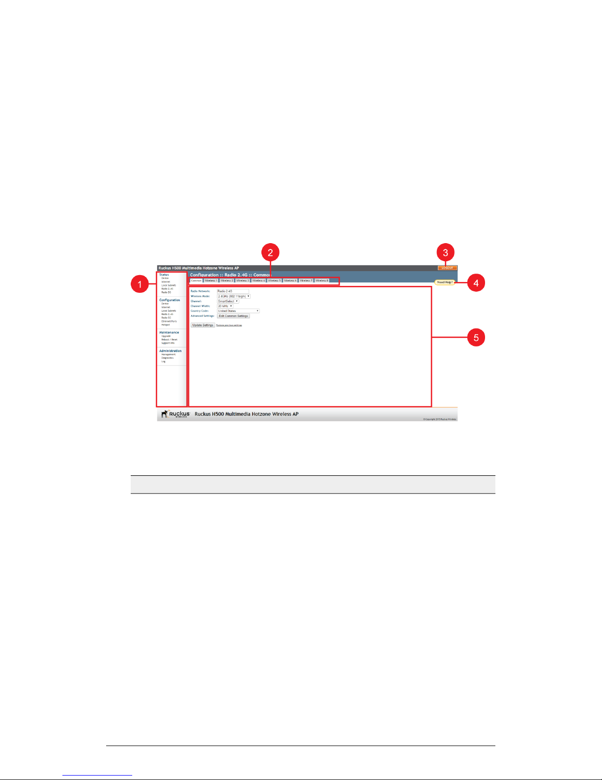
88
Navigation
Navigating the Web Interface
You can manage the AP through a web browser-based user interface that is accessible
from any networked computer or mobile device.
The following figure and table describe the ZoneFlex Access Point web interface
components.
3
Figure 45: Elements of the Ruckus Wireless AP Web Interface
Table 41: Ruckus Wireless AP Web interface elements
DescriptionElementNo.
Menu1
Tabs2
Help Button4
Under each category (Status, Configuration,
etc.) are options that, when clicked, open the
related workspace in the area to the right.
Contains additional options for the
configuration page. For example, the
Configuration > Wireless page includes one
tab for common wireless configuration and
eight tabs for each of the available WLANs.
Click this button to log out of the AP.LOGOUT Button3
Click this button to open a help window with
information related specifically to the options
currently displayed in the workspace.
ZoneFlex Indoor Access Point Release 104.0 User Guide
88
Page 89
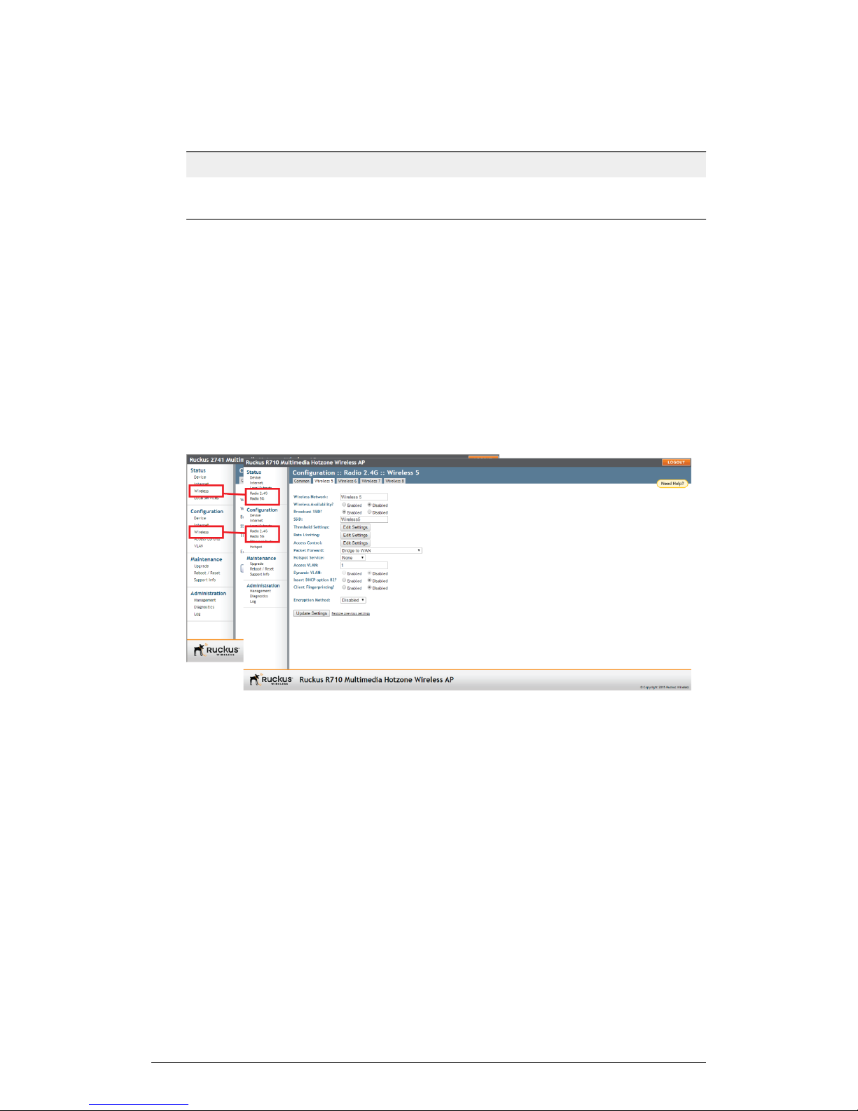
Navigation
When You Are Using a Dual-Band AP
DescriptionElementNo.
Workspace5
This large area displays features, options and
indicators relevant to your menu bar choices.
When You Are Using a Dual-Band AP
When your Ruckus Wireless AP model is a dual-band AP, note that elements on the
web interface menu are slightly different from single-band Ruckus Wireless AP models.
Dual-band APs have one 2.4 GHz radio (for 802.11b/g/n clients) and one 5 GHz radio
(for 802.11a/n/ac clients). The wireless settings for these two radios need to be configured
separately, which is why the dual-band AP web interface has the Radio 2.4G and Radio
5G menu items, instead of a single Wireless menu item in single-band models.
The following figure highlights the differences between single-radio AP and two-radio
AP menus.
Figure 46: Menu items are slightly different in single-band APs (left) and dual-band AP models
(right)
ZoneFlex Indoor Access Point Release 104.0 User Guide
89
Page 90

90
Configuration
Configuring the AP
Configure Device, Internet and Wireless settings for standalone operation or FlexMaster
management.
NOTE If you plan to manage your Ruckus Wireless network using SmartZone or
ZoneDirector controller, refer to their respective user documents, available from the
Ruckus Wireless Support site: http://support.ruckuswireless.com.
If the AP is to be run in a standalone configuration or is to be managed by a FlexMaster
manager, then continue with this section.
In this chapter:
• Configuring Device Settings on page 90
• Configuring Internet Settings on page 92
• Configuring Wireless Settings on page 99
• Configuring Ethernet Ports on page 116
• Configuring Hotspot Service on page 121
Configuring Device Settings
Device settings refer to the device name, location, service provider login and other
settings.
4
NOTE Some configuration options are available on specific AP models only.
1. Select Configuration > Device. The Configuration > Device page appears.
ZoneFlex Indoor Access Point Release 104.0 User Guide
90
Page 91
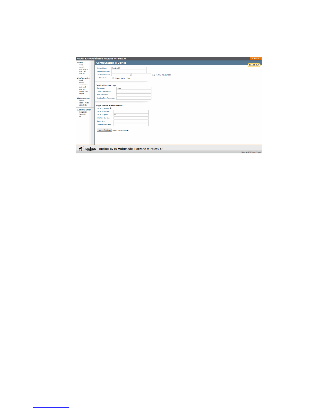
Figure 47: The Configuration > Device page
Configuration
Configuring the AP
2. In Device Name, type a new name for the device or leave as is to accept the default
device name (RuckusAP). The device name identifies the AP among other devices
on the network.
3. Optionally, enter Device Location and GPS Coordinates to keep track of the physical
location of the AP.
4. In Temperature Update (specific models only), enter the interval (in seconds) to
record the internal temperature of the device.
5. Under LED Control (specific models only), check the Disable Status LED(s) box to
turn off the status LEDs. This can be useful when the AP is installed in a public
location, to avoid drawing attention to the AP.
6. Under Service Provider Login, change the login information as required:
• Username: Type the name that you want to use for logging into the web interface.
The default user name is super.
• Current Password: When you are changing the password, enter the existing
password here.
• New Password: When you are changing the password, type the new password
that you want to use. The default password is sp-admin. The password must
consist of six to 32 alphanumeric characters only.
• Confirm New Password: Retype the new password to confirm.
7. Under Login remote authentication, click the TACACS+ State box to enable
TACACS+ authentication, if required. Terminal Access Controller Access-Control
System Plus (TACACS+) is an AAA protocol used to authenticate administrator login
to this device. Users can be authenticated/authorized to monitor, operate or configure
this device. Default is disabled. Administrators can be assigned any of the following
three administration privilege levels:
ZoneFlex Indoor Access Point Release 104.0 User Guide
91
Page 92

Configuration
Configuring the AP
• Super Admin (Perform all configuration and management tasks)
• Operator Admin (Change settings affecting single AP's only)
• Monitoring Admin (Monitoring and viewing operation status only)
8. If TACACS+ server state is enabled, then configure the TACACS+ server settings:
• TACACS+ server: IPv4 or IPv6 server address.
• TACACS+ port: 49 is the default, but it can be set to any available TCP port.
• TACACS+ Service: Login name.
• Share Key: TACACS+ Password.
• Confirm Share Key: TACACS+ Password.
9. Click Update Settings to save and apply your changes.
Configuring Internet Settings
Internet settings define how the AP connects to your local area network and to the
Internet.
This section describes how to view and configure the AP's Internet settings. Topics
discussed include:
• VLAN Settings Overview on page 92
• Configuring NTP Server and Management VLAN on page 93
• Default IP Addressing Behavior on page 93
• Obtaining and Assigning an IP Address on page 93
• Configuring L2TP Connection Settings on page 97
• Configuring Local Subnets on page 98
VLAN Settings Overview
Configuring VLANs is optional. You can configure ZoneFlex APs as part of an existing
VLAN network segmentation strategy, or place them into a VLAN of their own to separate
the wireless network infrastructure from other network segments, for example.
A Ruckus Wireless AP is in many ways like a network switch, with the capability to service
Wi-Fi connections. As such, like many advanced switches, Ruckus APs conform to the
IEEE 802.1Q standard -- the standard that defines virtual LANs. In an 802.1Q switch,
the concept of VLANs is always present. If a packet arrives without an 802.1Q header,
it is assigned to the "native VLAN" or "untag VLAN."
Each of the AP's wireless interfaces can be assigned to a single VLAN. When a packet
enters the AP through its wireless interface, the packet is assigned to the Access VLAN
configured on the Configuration > Wireless page (by default, 1).
AP Ethernet ports however, can be configured to pass all VLAN traffic (Trunk Ports) or
multiple specific VLANs (General ports).
The VLAN displayed in the web interface shows the AP's view of the VLAN environment;
when a packet arrives at an AP's Ethernet port, the port's VLAN configuration helps
determine if the packet is accepted or not (VLAN membership), and assigns a default
VLAN (untag VLAN) if the packet contains no 802.1Q header.
92
ZoneFlex Indoor Access Point Release 104.0 User Guide
Page 93

Configuration
Configuring the AP
In general, if your network has VLANs deployed already, you should apply VLAN
configuration to Ruckus APs so that the configuration across the network is consistent.
Configuring NTP Server and Management VLAN
A Network Time Protocol (NTP) Server should be configured to ensure that the AP
maintains the correct time.
NTP Server
The default Ruckus Wireless NTP Server (ntp.ruckuswireless.com) can be used if you
do not have an NTP server on your network.
If you want the AP to contact a different NTP server, you can do so by going to
Configuration > Internet and entering the host name in NTP Server at the top of the
page.
Management VLAN
CAUTION! Changing the Management VLAN causes you to be immediately
disconnected from the web interface if the computer you are using is not on the same
VLAN. Do not change the Management VLAN unless your admin PC is on the same
VLAN. Otherwise, you will be disconnected and unable to connect again without factory
resetting the AP.
If you want to place this AP's management traffic into a management VLAN, enter the
VLAN ID in the Management VLAN field and then click Update Settings.
Default IP Addressing Behavior
By default, the AP is configured to automatically obtain an IPv4 address from a DHCP
server on the network.
If the AP does not detect a DHCP server, it automatically assigns itself the static IP
address 192.168.0.1 to make it easier for you to preconfigure and deploy it on your
network.
For IPv6, the Auto Configuration setting serves the same purpose as DHCP. The default
static IPv6 address is fc00::1.
Obtaining and Assigning an IP Address
There are three methods of assigning IP addresses to the AP.
See the following topics for the IP address assignment method you wish to use:
• DHCP / Auto Configuration on page 94
• Configuring Static IP on page 95
• Configuring PPPoE on page 96
ZoneFlex Indoor Access Point Release 104.0 User Guide
93
Page 94
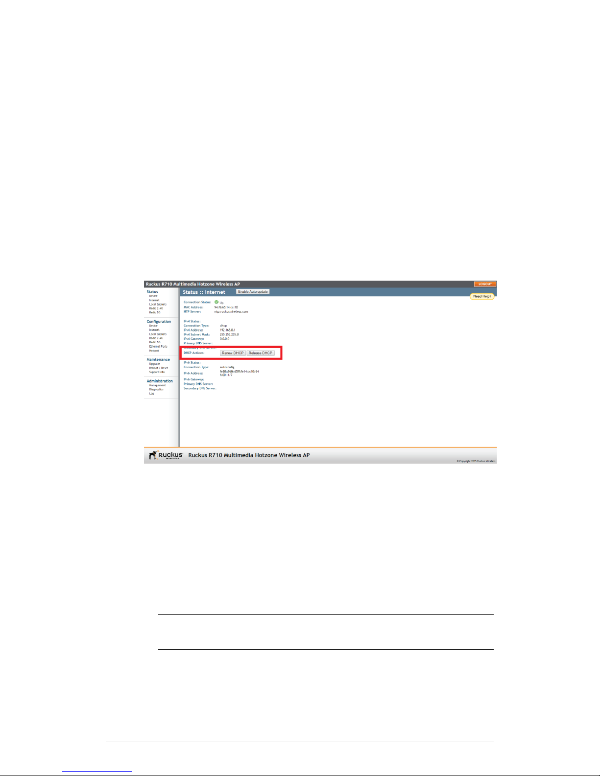
Configuration
Configuring the AP
DHCP / Auto Configuration
If you leave the AP at its default configuration, it attempts to obtain an IPv4 address from
a DHCP server on the network.
In an IPv6 network environment, the AP attempts to obtain an IPv6 address from an
IPv6 Auto Configuration server.
Renewing and Releasing DHCP
This task should be performed only if you have access to the DHCP server or have some
way to determine what IP address has been assigned to the AP.
It serves as a troubleshooting technique when IP addresses to one or more networked
devices are unusable or in conflict with others, or when the AP loses its DHCP-assigned
IP address for some reason.
1. Go to Status > Internet.
Figure 48: Renew or Release DHCP
2. Review the current settings.
3. If the current Connection Type is DHCP, you are able to see the currently-assigned
IP address and subnet mask listed below.
• To force the AP to release its DHCP-assigned IP address, click Release DHCP.
This disconnects the user from web interface as the system reverts to its default
IP address. Log in to the device using the default IP address (192.168.0.1) and
click on Renew DHCP to request a new lease from the DHCP server.
• Click Renew DHCP to request a new IP address lease from the DHCP server.
NOTE The IP address may or may not change depending on the lease time
offered to this device.
94
ZoneFlex Indoor Access Point Release 104.0 User Guide
Page 95
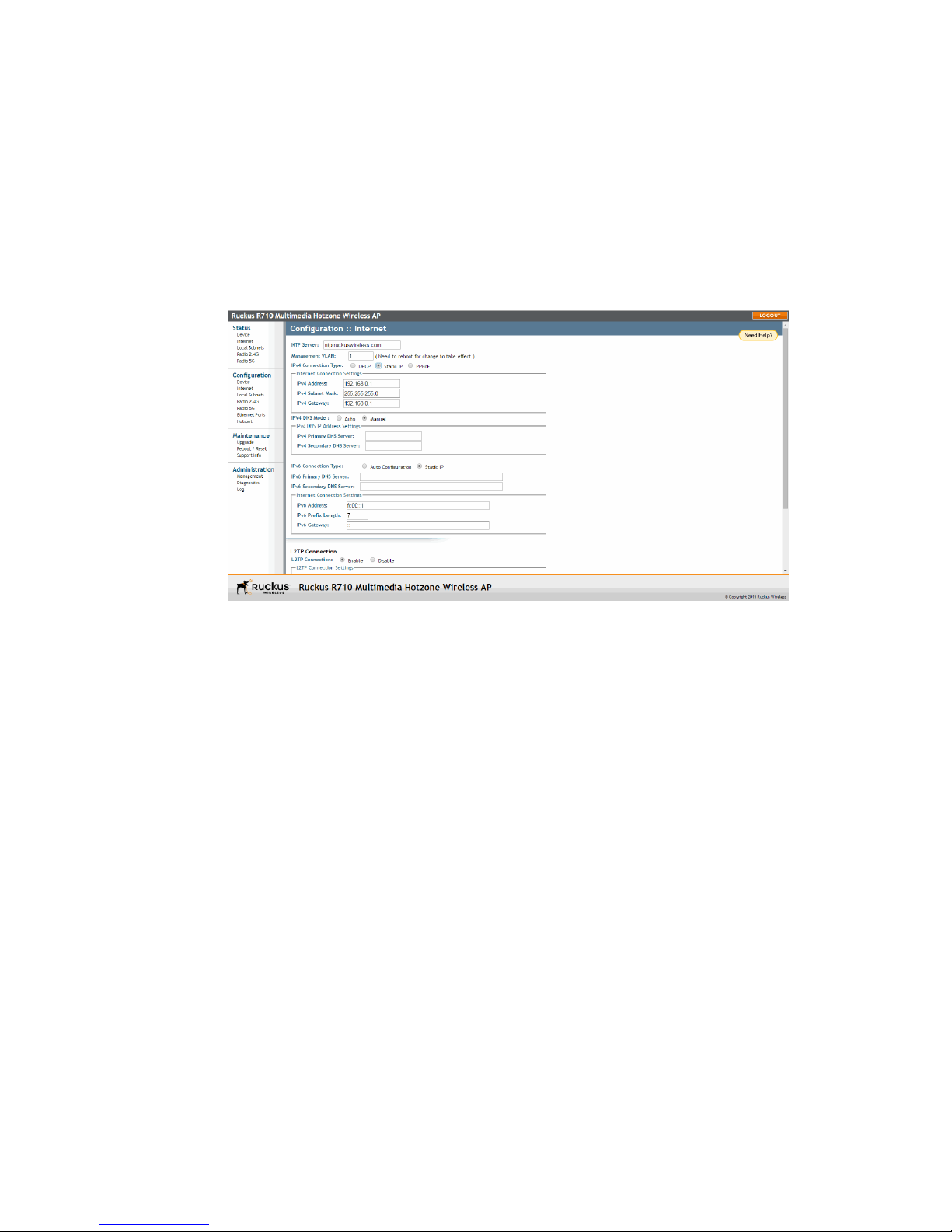
Configuration
Configuring the AP
4. Click Update Settings to save your settings.
Configuring Static IP
Unless you are able to determine the IP address assigned to the AP by the DHCP/Auto
Configuration server, it can be useful for anyone needing administrative access to
configure a static IP address.
1. Go to Configuration > Internet. The Configuration :: Internet page appears.
Figure 49: The Configuration > Internet page
2. You can configure static addresses for IPv4, IPv6 or both. The AP maintains both
sets of IP address settings when both are configured.
Static IPv4
Use the following procedure to configure a static IPv4 address.
1. In IPv4 Connection Type, select Static IP.
2. When the Internet Connection Settings options appear, you can make changes to
the following settings:
• IPv4 Address: Enter the static IP address that you want to assign to the AP in
IPv4 (dot-decimal) format.
• IPv4 Subnet Mask: Enter the subnet mask for the network.
• IPv4 Gateway: Enter the gateway IP address of the Internet interface.
3. To allow the DNS mode to be determined automatically, set IPV4 DNS Mode to
Auto.
4. To set the DNS mode manually, set IPV4 DNS Mode to Manual. Then enter the
following:
• IPv4 Primary DNS Server: The IP address of the primary Domain Name System
(DNS) server.
ZoneFlex Indoor Access Point Release 104.0 User Guide
95
Page 96

Configuration
Configuring the AP
• IPv4 Secondary DNS Server: The IP address of the secondary DNS server.
5. Continue with Static IPv6 on page 96, or
6. Click Update Settings to save your changes.
Static IPv6
Configuring a static IPv6 address is optional.
1. In IPv6 Connection Type, select Static IP.
2. When the Internet Connection Settings options appear, you can make changes to
the following settings:
• IPv6 Primary DNS Server: The IP address of the primary Domain Name System
(DNS) server.
• IPv6 Secondary DNS Server: The IP address of the secondary DNS server.
• IPv6 Address: Enter the static IP address that you want to assign to the AP in
IPv6 (colon-separated) format.
• IPv6 Prefix Length: Enter the prefix length for the network.
• IPv6 Gateway: Enter the gateway IP address of the Internet interface.
3. Click Update Settings to save your changes.
Configuring PPPoE
Use the following procedure to configure PPPoE addressing for the AP.
Point to Point Protocol over Ethernet (PPPoE) is a Layer 2 protocol which uses the PPP
(Point to Point) protocol to connect a client system to a server system over a one to one
network link. All traffic for a PPPoE connected client must go through the PPPoE server
to reach the client. A PPPoE server can therefore be used to route, NAT, firewall, and
perform QoS traffic shaping.
If a PPPoE server is used to distribute Internet access to subscribers, the AP can be
configured with a PPPoE username and password to authenticate with the PPPoE server.
PPPoE is available only for the IPv4 connection type; PPPoE is not supported in IPv6
environments.
1. Go to Configuration > Internet.
2. Under IPv4 Connection Type select PPPoE.
3. Enter a PPPoE Username.
4. Enter a PPPoE Password.
5. Retype the password in PPPoE Password Confirmation.
6. To allow the DNS mode to be determined automatically, set IPV4 DNS Mode to
Auto.
7. To set the DNS mode manually, set IPV4 DNS Mode to Manual. Then enter the
following:
96
ZoneFlex Indoor Access Point Release 104.0 User Guide
Page 97
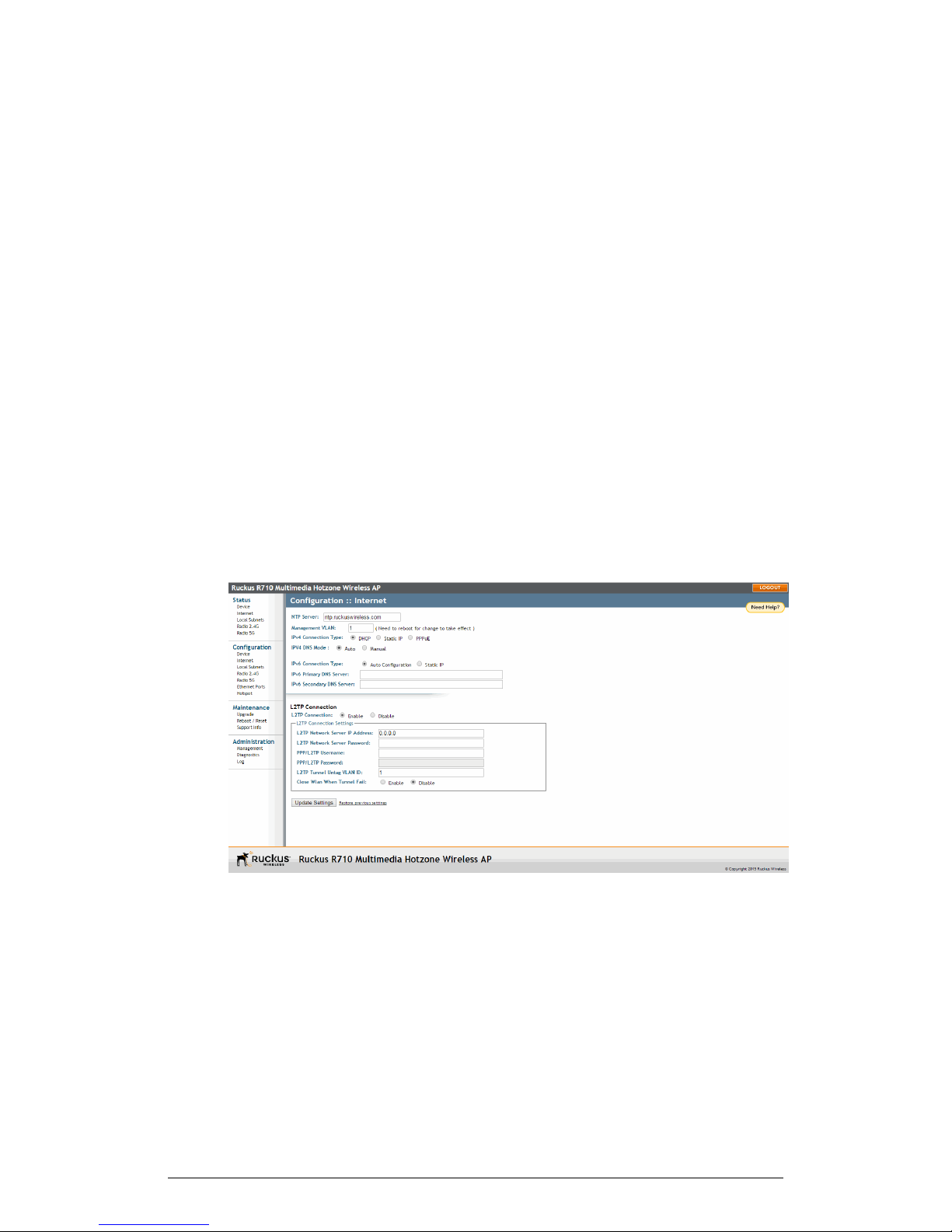
Configuration
Configuring the AP
• IPv4 Primary DNS Server: The IP address of the primary Domain Name System
(DNS) server.
• IPv4 Secondary DNS Server (optional): The IP address of the secondary DNS
server.
8. Click Update Settings to save your changes.
Configuring L2TP Connection Settings
Use the following procedure to configure Layer 2 Tunneling Protocol settings.
You can implement transparent bridging by using L2TP (Layer 2 Tunneling Protocol)
tunneling. By tunneling traffic from an AP to a centralized data center, access controllers
with policy enforcement software can apply rules and services. In a typical WLAN
implementation, these rules include a captive portal to authenticate users' credentials.
In the case of L2TP, the Ruckus Wireless AP functions as a remote bridge. As such, it
forwards traffic into PPP sessions over the L2TP tunnel. This implementation ensures
that you have complete visibility into MAC addresses of users, as individual Wi-Fi clients
are essentially placed (bridged) onto the ISP's core network.
1. Go to Configuration > Internet.
2. Under L2TP Connection, click Enable.
Figure 50: L2TP Connection
3. In L2TP Network Server IP Address, type the IP address of the L2TP network
server (LNS) to which the device connects.
4. In L2TP Network Server Password, type the L2TP server password.
5. If your network requires PPP authentication, configure the following fields under
L2TP/PPP Authentication:
ZoneFlex Indoor Access Point Release 104.0 User Guide
97
Page 98
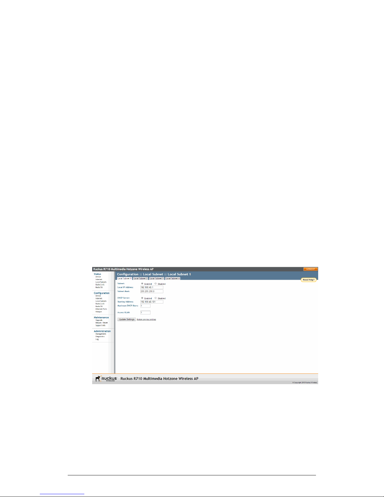
Configuration
Configuring the AP
• Username: Type your PPP user name.
• Password: Type the password for the account.
• L2TP Tunnel Untag VLAN ID: Enter the Untag VLAN ID for the L2TP tunnel.
6. In Close WLAN When Tunnel Fail, select Enable if you want to disable the WLAN
when the tunnel connection is lost. This prevents clients from remaining connected
to the WLAN but without Internet connectivity.
7. Click Update Settings to save your settings.
Configuring Local Subnets
Ruckus Wireless APs can be configured to provide routing/network address translation
(NAT) functionality by using the Local Subnets feature.
When a Local Subnet is enabled, the standalone AP serves as a gateway router with
the ability to manage its own subnets, providing DHCP server and DNS cache functions
for both wired and wireless clients. These clients can be assigned private IP addresses
from a user-defined address pool. Traffic from the client station in private address space
appears on the outside as if generated by the AP itself. In this way, the AP performs
Layer 3 packet forwarding not only for Hotspot/WISPr usage, but for standard usage
as well.
Up to four IP subnets can be configured per AP, each with its own address range which
cannot conflict with one another.
1. Go to Configuration > Local Subnets. The four tabs at the top (Local Subnet 1 -
4) allow you to configure each of the four subnets independently.
Figure 51: Configuring local subnets and enabling router mode
2. Click Enabled next to Subnet. The local subnet configuration options appear.
98
ZoneFlex Indoor Access Point Release 104.0 User Guide
Page 99

Configuration
Configuring the AP
3. In Local IP Address, enter an IP address for the gateway. The default address for
Subnet 1 is 192.168.40.1. This address can be used to access the AP's web
interface for configuration and monitoring from devices connected to this subnet.
4. In Subnet Mask, typically you would want to leave the setting at its default value
(255.255.255.0) for a Class C subnet with an address pool of up to 254 addresses.
An error appears if you enter an invalid IP/netmask combination.
5. In DHCP Server, click Enabled if you want to enable DHCP for this subnet. Starting
Address and Maximum DHCP Users fields appear.
6. In Starting Address, enter an address in the same subnet as the Local IP Address
(e.g., 192.168.40.2).
7. In Maximum DHCP Users, enter the maximum number of clients that can be
assigned addresses by DHCP in this subnet (valid values are 1-253 if the default
subnet mask is used).
8. In Access VLAN, enter a VLAN ID to segment client traffic arriving from this subnet
from other network traffic. (Example: if you use the default 192.168.40.1 address
range, you may want to use "40" as the VLAN for this subnet.)
9. Click Update Settings to save your changes. The local subnet is created immediately
and can now be applied to WLANs or Ethernet ports from their respective configuration
pages.
Configuring Wireless Settings
This section describes how to configure the wireless settings of the AP.
There are two types of wireless settings that you need to configure:
• Configuring Common Wireless Settings on page 99: Includes the wireless mode,
country code, and advanced wireless settings, such as the wireless transmit power
and wireless protection mode. These settings are applied to all WLANs.
• Configuring Wireless # (WLAN Number) Settings on page 104: The Wireless # tabs
(“Wireless 1” through “Wireless 8” on the 2.4 GHz radio and “Wireless 9” through
“Wireless 16” on the 5 GHz radio) provide settings for customizing each WLAN
individually.
Configuring Common Wireless Settings
Common wireless settings are settings that are applied to all WLANs.
On single radio APs, go to Configuration > Wireless. On dual radio APs, you configure
these settings for the 2.4 GHz and 5 GHz radios independently by going to Configuration
> Radio 2.4G or Configuration > Radio 5G.
1. Go to Configuration > Wireless. The Configuration > Wireless > Common page
appears.
ZoneFlex Indoor Access Point Release 104.0 User Guide
99
Page 100
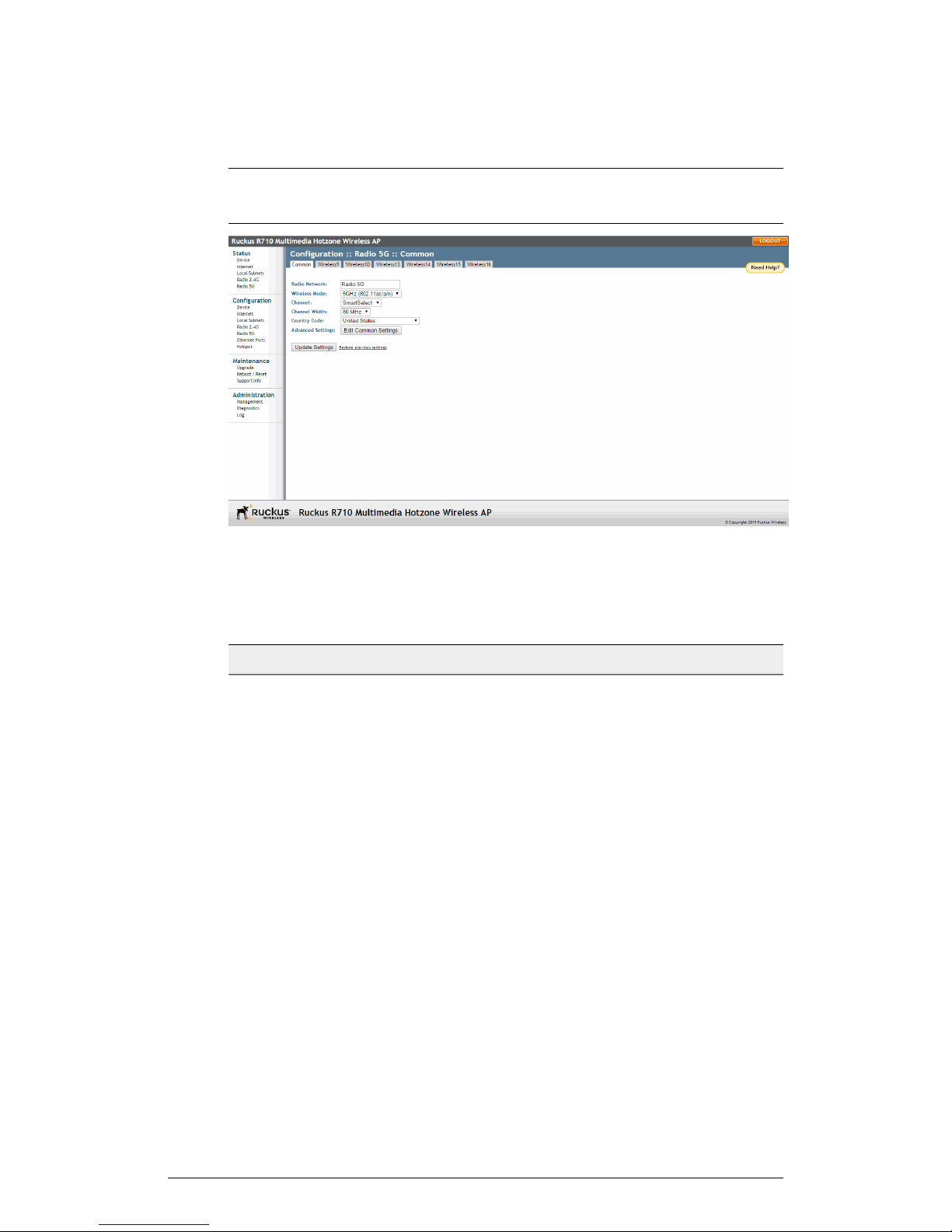
Configuration
Configuring the AP
NOTE If you are using a dual-band AP, then go to Configuration > Radio 2.4G or
Configuration > Radio 5G.
Figure 52: The Configuration > Wireless > Common page
2. Make changes to the common wireless settings listed in the following table.
Table 42: Common Wireless settings
DescriptionSetting
Radio Network
Wireless Mode
(Dual radio APs only) Allows you to change the name of
the 2.4GHz and 5GHz radios (default: “Radio 2.4G” and
“Radio 5G”).
On 802.11b/g APs: The wireless mode options include
the following: Auto-Select: Allows both 802.11g- and
802.11b-compliant devices to connect to the network.
This is the default setting. 2.4GHz 54 Mbps (For faster
802.11g devices only): Allows only 802.11g-compliant
devices to join the network. 2.4GHz 11Mbps (For slower
802.11b devices only): Allows only 802.11b-compliant
devices to join the network. On dual radio 802.11n/ac
APs: On dual radio 802.11n APs, the wireless mode is
determined by radio: For the 2.4GHz radio, the mode is
set to 2.4GHz (802.11b/g/n), while for the 5GHz radio,
the mode is set to 5GHz (802.11a/n/ac).
100
ZoneFlex Indoor Access Point Release 104.0 User Guide
 Loading...