

ZoneFlex 7441 Dual Band
802.11n DAS Access Point
Quick Setup Guide
This Quick Setup Guide provides step-by-step instructions on
how to set up your Ruckus Wireless ZoneFlex Access Point. After
completing the steps described in this Guide, you will be able to
place the Access Point (AP) at your site and provide wireless
network access to users.
BEFORE YOU BEGIN
Before deploying Ruckus Wireless products, please check for the
latest software and the release documentation.
• User Guides and Release Notes are available at
http://support.ruckuswireless.com/documents.
• Software Upgrades are available at
http://support.ruckuswireless.com/software.
• Open Source information is available at
http://opensource.ruckuswireless.com.
• Software License and Limited Warranty available at
http://support.ruckuswireless.com/warranty.
PACKAGE CONTENTS
• ZoneFlex 7441 Access Point
• ZoneFlex 7441 Installation Guide
• Mounting Brackets
• Mounting accessory bag (DIN rail clip, 4 screws for mounting
ears, terminal ring for ground wire)
• Regulatory flyer
• Declaration of Conformity (country-dependent)
• Product Warranty Statement
•This Quick Setup Guide
SETUP REQUIREMENTS
• A computer running Windows 7 (procedures for other OS’s
are similar)
• One or more of the following:
• A modem (DSL or cable), broadband router, or other
device provided by your Internet Service Provider that
brings Internet access to your site.
• A network switch or a DSL/Internet gateway device.
• An Ethernet cable (Cat5e or better for PoE in)
• An AC power adapter (sold separately), or
• An 802.3af or 802.3at -compliant Power over Ethernet (PoE)
switch or PoE injector, or
• AC/DC adapter 12V 1.5A (Ruckus part #902-0169-xx00, or
equivalent)
IMPORTANT!
If the AP is deployed with a ZoneDirector, follow the
ZoneDirector Quick Setup Guide, and connect the AP to your
local network.
STEP 1: CONNECT THE AP TO YOUR COMPUTER
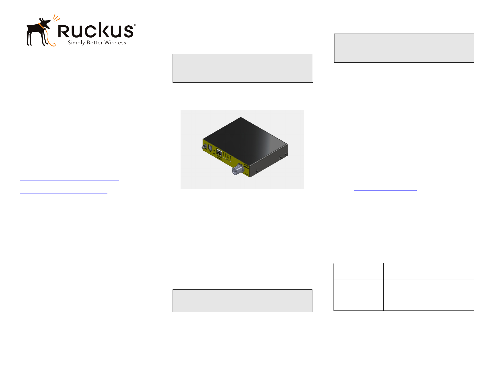
Figure 1. ZoneFlex 7441 DAS Access Point
1 After removing your Ruckus Wireless AP from its package,
place it next to your computer.
2 Using an Ethernet cable, connect your computer’s network
port to the 10/100/1000 port on the AP.
3 Using the AC adapter (sold separately), connect the AP to a
convenient (and protected) power source.
• Alternatively, connect the 10/100/1000 port to a PoE
injector or PoE switch for both power and network connectivity.
4 Verify that the Power LED on the external enclosure is a
steady green.
STEP 2: PREPARE YOUR COMPUTER FOR AP
ETUP
S
NOTE:
The following procedures assume Windows 7 as the operating
system. Procedures for other OS’s are similar.
1 On your Windows 7 computer, configure your network
adapter from the Local Area Connection settings as follows:
Start > Control Panel > Network and Sharing
•
Center > Change Adapter Settings
2 Edit the TCP/IPv4 address settings as follows:
•
Local Area Connection > Properties > Internet
Protocol Version 4 (TCP/IPv4) > Properties
The TCP/IPv4 Properties dialog box appears.
IMPORTANT!
Write down all of the currently active settings so you can
restore your computer to its current configuration later (when
this process is complete).
3 Select Use the following IP address (if it is not already
selected) and then make the following entries:
•
IP address: 192.168.0.22 (or any address in the
192.168.0.x network)
•
Subnet mask: 255.255.255.0
Default gateway: 192.168.0.1
•
Leave the
4 Click OK to save your changes.
Your changes are put into effect immediately.
DNS server fields empty.
STEP 3: LOG INTO THE AP
As specified earlier, the AP should be directly connected to your
computer (through the Ethernet port) and powered on, ready for
setup.
1 On your computer, open a Web browser window.
2 In the browser, type this URL to connect to the AP:
https://192.168.0.1
3 Press <Enter> to initiate the connection. When a security
alert dialog box appears, click
4 When the Ruckus Wireless Admin login page appears, enter
the following:
Username: super
•
Password: sp-admin
•
5 Click Login.
Default AP Settings (For Your Reference)
Network Names
(SSIDs)
Security (Encryption
method)
Default Management
IP Address
Wireless1—Wireless8
Disabled for each wireless interface
192.168.0.1
OK/Yes to proceed.
Copyright © 2013 Ruckus Wireless, Inc. Page 1 of 2
Published April 2013, Part Number 800-70437-001 Rev A
STEP 4: CUSTOMIZE THE WIRELESS SETTINGS
1 On the Web interface menu, click Configuration > Wire-
less. The Configure :: Wireless :: Common options appear.
2 Verify that the following options are active:
•
Channel: SmartSelect
Country Code: If you are not located in the United
•
States, select your current country.
3 Click Update Settings if you made any changes.
4 Click any of the eight “Wireless #” tabs at the top of the
page.
5 In Wireless Availability, click Enabled.
6 Delete the text in the SSID field, and then type a name for
your network that will help your users identify the AP in their
wireless network connection application.
7 Click Update Settings to save your changes.
8 Repeat Steps 4-7 for each Wireless # interface that you want
to enable.
9 Click Logout to exit the Web interface.
STEP 5: PLACE THE AP IN YOUR SITE
1 Move the AP to its permanent location (accessible to both
AC power and network connection).
2 Use an Ethernet cable to connect the 10/100/1000 port of
the AP to your network.
NOTE:
If you will be using PoE, you will need a Cat5e (or better)
Ethernet cable to connect the AP to the PoE injector or switch.
3 Connect the AC power adapter (or PoE power supply) to the
AP, then to a convenient power source.
4 Verify that the 10/100/1000 port LED is lit.
Congratulations! Your wireless network is active and ready for
use.
(OPTIONAL) MOUNTING INSTRUCTIONS
The ZoneFlex 7441 mounting options include desktop, wall
mounting (flat), wall mounting (horizontal), and DIN rail
mounting.
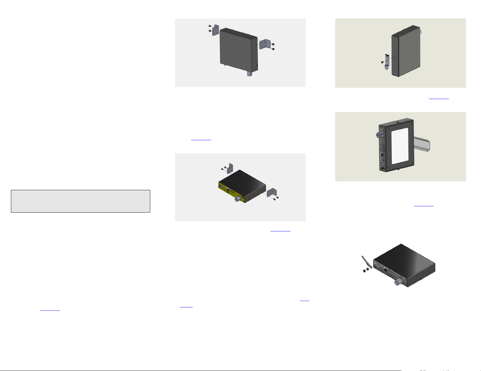
Wall Mounting (Flat)
1 Attach the wall mounting brackets to the ZoneFlex 7441 as
shown in
Figure 2.
Figure 2. Flat wall mount
2 Place the AP on the wall and mark the locations for screw
holes.
3 Drill screw holes, place the AP onto the wall and insert
screws.
Wall Mounting (Horizontal)
The ZoneFlex 7441 can be mounted to a wall horizontally as
shown in
Figure 3.
Figure 3. Horizontal wall mount
1 Attach the brackets to the AP as shown in Figure 3.
2 Place the AP on the wall and mark the locations for screw
holes.
3 Drill screw holes, place the AP onto the wall and insert
screws.
DIN Rail Mounting
Use the DIN rail clip on the rear of the AP to connect mount to a
DIN rail.
1 Remove the screw on the housing back wall and use to
attach the DIN rail clip to the rear of the AP as shown in
Fig-
ure 4. The clip has a tab to prevent rotation which fits into
the corresponding slot in the housing.
Figure 4. DIN rail clip
2 Mount the AP to the DIN rail as shown in Figure 5.
Figure 5. DIN rail mounting
Grounding the Access Point
1 Attach ground wire to the AP using the included terminal
ring and two hex nuts as shown in
ring can accommodate wire sizes ranging from 16 to 25
gauge.
Figure 6. The terminal
Figure 6. Grounding the AP
DIN Rail Removal
A large, flat screwdriver inserted from the bottom of the
product can be used to pry the clip off the rail.
Copyright © 2013 Ruckus Wireless, Inc. Page 2 of 2
Published April 2013, Part Number 800-70437-001 Rev A
 Loading...