

Page 1

Outdoor Wireless Access Point
OW-1000A
User’s Manual
B
EFORE INSTALLING THE UNIT, PLEASE READ THIS MANUAL THOROUGHLY, AND RETAIN
IT FOR FUTURE REFERENCE
.
1
Page 2

Notice:
The unit must be used 12V, 1A power
adaptor for PoE power supply!
The unit would be dead when using
wrong power supply!
2
Page 3

Ź Contents
Chapter 1. Introduction............................................................................................... 5
1.1 Introducing the OW-1000A.......................................................................... 5
1.2 Product Features........................................................................................... 5
1.3 Package Contents .......................................................................................... 5
1.4 System Requirements ................................................................................... 6
1.5 Inline Power Injector (PoE) ......................................................................... 6
Chapter 2. Installation and Basic Configuration ...................................................... 7
2.1 Before You Start ............................................................................................ 7
2.2 Locate the OW-1000A and Inline Power Injector Ports............................ 8
2.3 Preparing Installation................................................................................... 9
2.4 Basic Configuration .................................................................................... 10
2.4.1 Basic Configuration Steps................................................. 10
2.4.2 Logging into the Web Interface .................................... 10
2.4.3 Set Operating Mode, IP Address, Subnet Mask,
Default Route IP, DNS Server IP of OW-1000A................... 13
2.4.4 Set Wireless SSID for Wireless Interface ............... 15
2.4.5 Set Wireless Encryption for Wireless Interface .. 16
2.4.6 Change Supervisor Account & Password................. 17
2.4.7 Upgrade the Firmware ........................................................ 18
Chapter 3. Network Topologies................................................................................. 19
3.1 Wireless Client Bridge-to-Central Wireless Bridge................................. 20
Chapter 4. All function on Device............................................................................. 21
4.1 SYSTEM ...................................................................................................... 21
4.1.1 Administrator
4.1.2 Firmware..................................................................................... 22
4.1.3 Configuration Tools............................................................... 23
4.1.4 Status ............................................................................................ 24
4.1.5 Log .................................................................................................. 25
4.1.6 System Time.............................................................................. 26
4.1.7 Reboot........................................................................................... 27
4.2 NETWORK ................................................................................................. 28
4.2.1 Network ....................................................................................... 28
4.2.2 HotSpot炷Captive Portal炸................................................. 31
4.3 WIRELESS.................................................................................................. 32
4.3.1 Wi-Fi 1........................................................................................... 33
4.3.2 Wi-Fi 2........................................................................................... 33
4.3.3 Wi-Fi 3........................................................................................... 33
4.3.4 Wi-Fi 4........................................................................................... 33
4.4 ACL .............................................................................................................. 34
4.4.1 ACL for Wi-Fi 1......................................................................... 34
4.4.2 ACL for Wi-Fi 2......................................................................... 34
4.4.3 ACL for Wi-Fi 3......................................................................... 34
........................................................................... 21
3
Page 4

4.4.4 ACL for Wi-Fi 4......................................................................... 34
4.5 SNMP ........................................................................................................... 35
4.5.1 Agent Settings ......................................................................... 35
4.6 EXIT............................................................................................................. 35
Chapter 5. Specifications........................................................................................... 36
Chapter 6. Default Settings ....................................................................................... 39
6.1 SYSTEM ...................................................................................................... 39
6.1.1 Administrator ........................................................................... 39
6.1.2 Firmware..................................................................................... 39
6.1.3 Configuration Tools............................................................... 39
6.1.4 Status ............................................................................................ 39
6.1.5 Log .................................................................................................. 40
6.1.6 System Time.............................................................................. 40
6.1.7 Reboot........................................................................................... 40
6.2 NETWORK ................................................................................................. 41
6.2.1 Network ....................................................................................... 41
6.2.2 Hotspot......................................................................................... 41
6.3 WIRELESS.................................................................................................. 42
6.3.1 Wi-Fi 1........................................................................................... 42
6.3.2 Wi-Fi 2........................................................................................... 43
6.3.3 Wi-Fi 3........................................................................................... 44
6.3.4 Wi-Fi 4
........................................................................................... 45
6.4 ACL .............................................................................................................. 46
6.4.1 ACL for Wi-Fi ............................................................................. 46
6.4.2 ACL for Wi-Fi 2......................................................................... 46
6.4.3 ACL for Wi-Fi 3......................................................................... 47
6.4.4 ACL for Wi-Fi 4......................................................................... 47
6.5 SNMP ........................................................................................................... 48
6.6 EXIT............................................................................................................. 48
Chapter 7. Regulatory Compliance Information.................................................... 49
4
Page 5

Chapter 1. Introduction
1.1 Introducing the OW-1000A
The OW-1000A is fully interoperable with IEEE 802.11b/g compliant
Outdoor Wireless Last-mile product. The OW-1000A operates in AP mode
or remote bridge mode, and connects to OW-1000A AP/CB to construct
point-to-point as well as point-to-multipoint topologies, for maximum
flexibility in configuring building-to-building networks and WISP
functions.
1.2 Product Features
¾ Outdoor enclosure in compliance with versatile industrial IP
炷Ingress Protection炸 level covering IP65
¾ RF transmit power 802.11b mode @ 11Mbps data rate
¾ RF transmit power 802.11g mode @ 54Mbps data rate
¾ Embedded 9dBi patch directional antenna and one SMA
connector for external antenna used.
¾ Support 12VDC 1A Power-over-Ethernet炷PoE炸
¾ MAC address based access control
Hint: IP炷Ingress Protection炸
1.3 Package Contents
The product package contains the following items.
1. One (1) OW-1000AA Outdoor Wireless Access Point / Client
Bridge unit
2. One (1) 100~240VAC, 50~60Hz AC to 12V/1A DC switching
adapter
3. One (1) Inline Power Injector (PoE)
4. One (1) User manual CD-disc
5. One (1) wall mounting kit
6. One (1) band clamp
5
Page 6

1.4 System Requirements
Installation of the OW-1000A Outdoor Wireless Access Point/Client
Bridge requires the following:
1. A Windows-based PC/AT compatible computer 炷 PC system
requirement烉ţŦŵŵŦųġŵũŢůġőŊŊŊġĹııġŰųġŰŵũŦųġIJııĦġŤŰŮűŢŵŪţŭŦġŦŲŶŪűŮŦůŵġĭġŐŔ烉
ŸŪůťŰŸŴġ ijıııİřőġ 炸 or Ethernet data device with an available
RJ-45 Ethernet port to run the configuration program or with
TCP/IP connection to the Ethernet network.
2. A 10/100Base-T Ethernet RJ-45 Ethernet cable is connected to
Ethernet network.
3. An AC power outlet (100~240V, 50~60Hz) supplies the power.
1.5 Inline Power Injector (PoE)
The OW-1000A is equipped with an Inline Power Injector module. The
Inline Power Injector (PoE) delivers both data and power to OW-1000A
unit via a signal Ethernet cable, and gives the following benefits to
improve the performance vs. installation cost ratio.
¾ This works great in areas where you may not have power , like
house roof.
¾ This also allows you to place the OW-1000A unit closer to the
antenna, to make installation easier more thus reducing signal
loss over antenna cabling.
¾ Ethernet signal travels well over CAT 5 cable but 2.4GHz signal
doesn't do as well over antenna cabling.
¾ Ethernet cabling is much cheaper than Antenna cabling.
6
Page 7
Chapter 2. Installation and Basic Configuration
This chapter describes the procedures of installing the OW-1000A.
2.1 Before You Start
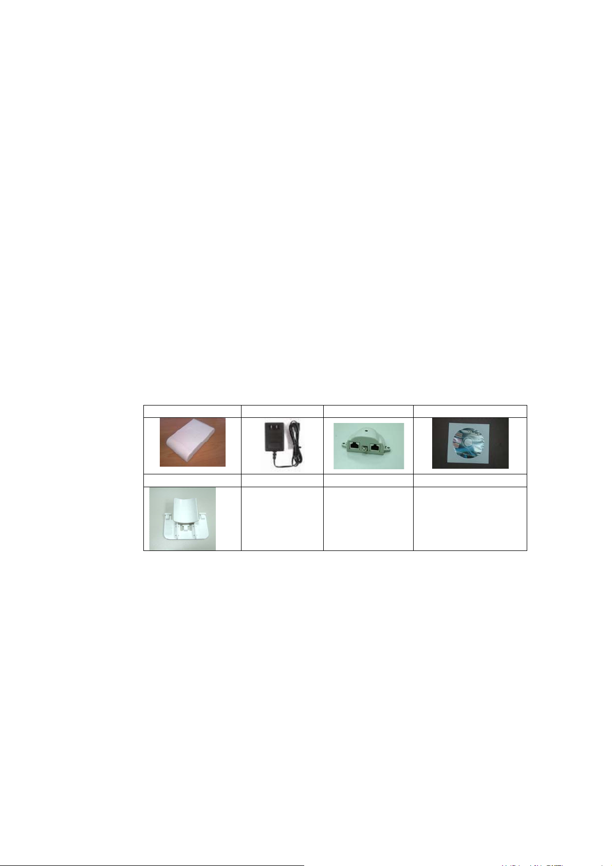
After unpacking the system, make sure the following items are present
and in good condition. Refer to below pictures for product image.
1. OW-1000A Outdoor Wireless Access Point/Client Bridge unit
2. 100~240VAC, 50~60Hz AC to 12V/1A DC switching adapter
3. Inline Power Injector (PoE) 12VDC, 1A
4. User manual CD-disc
5. Wall/mast mounting kit, including two (2) band clamp
1. Unit 2. Adapter 3. PoE 4. CD
5. Wall mount kit
7
Page 8
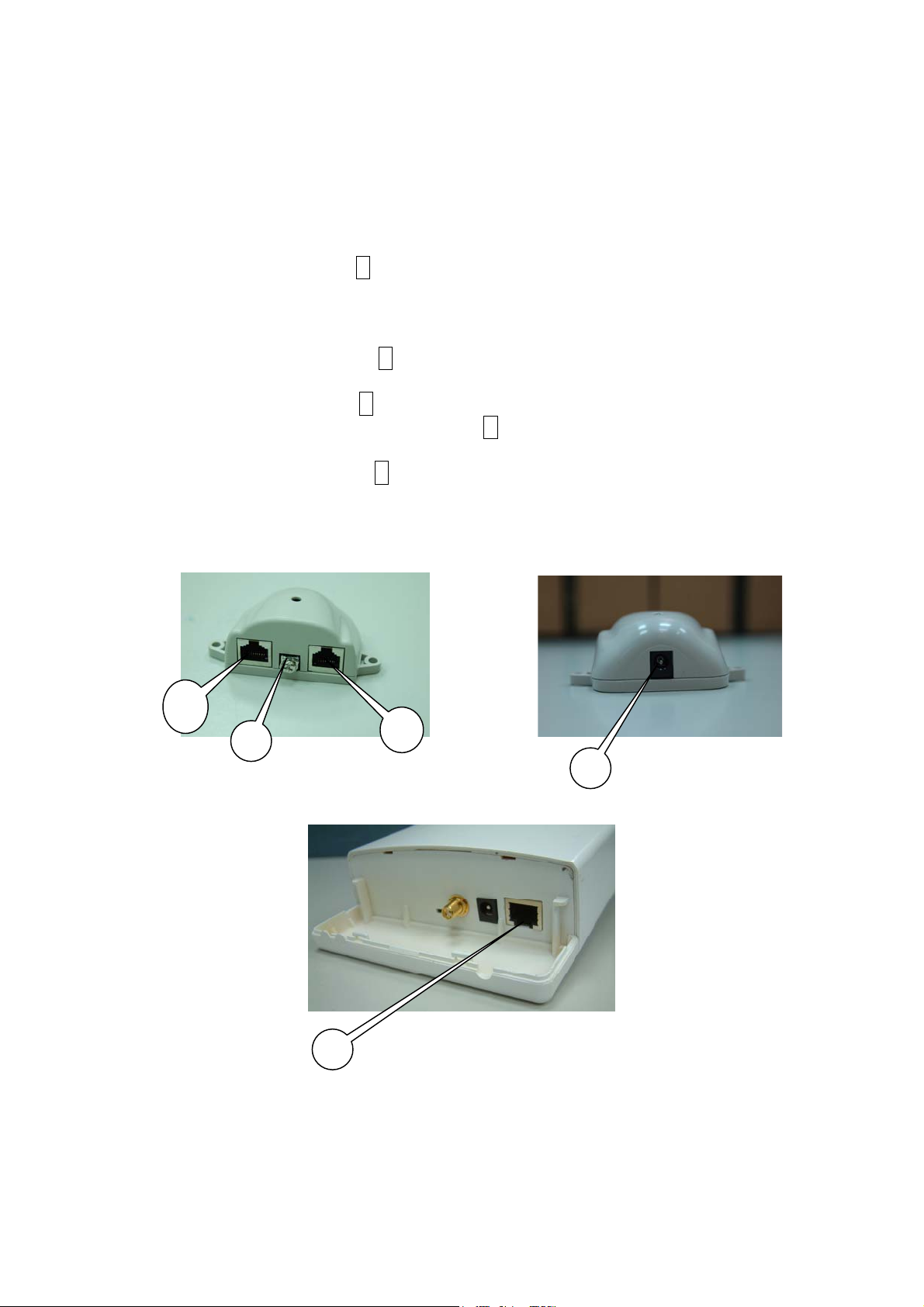
2.2 Locate the OW-1000A and Inline Power Injector Ports
ʇ Interface on the OW-1000A Unit
¾ Ethernet Port 1 : for connecting the 30m RJ-45 CAT-5
Ethernet cable.
ʇ Interface on the Inline Power Injector
¾ Data Input Port 2 : for connecting cross-over Ethernet Cable
to PC or straight Ethernet cable to Hub Switch Router .
¾ DC Input Port 3 : power adapter 12V, 1 DC input.
¾ Power & Data Output Port 4 : for connecting the 30m RJ-45
CAT-5 Ethernet Cable.
¾ Grounding Port 5 : for connecting grounding wire.
Device
4
5
POE picture1 POE picture2
2
3
1
Figure 2-1
Power and Data Interface location on the PoE denoted by numbers 1-6.
8
Page 9
ʇ
2.3 Preparing Installation
Before installing OW-1000A for outdoor application or hard-to-reach
location, we recommend configuring and test all the devices first.
For configuring the OW-1000A, please follow the quick steps below to
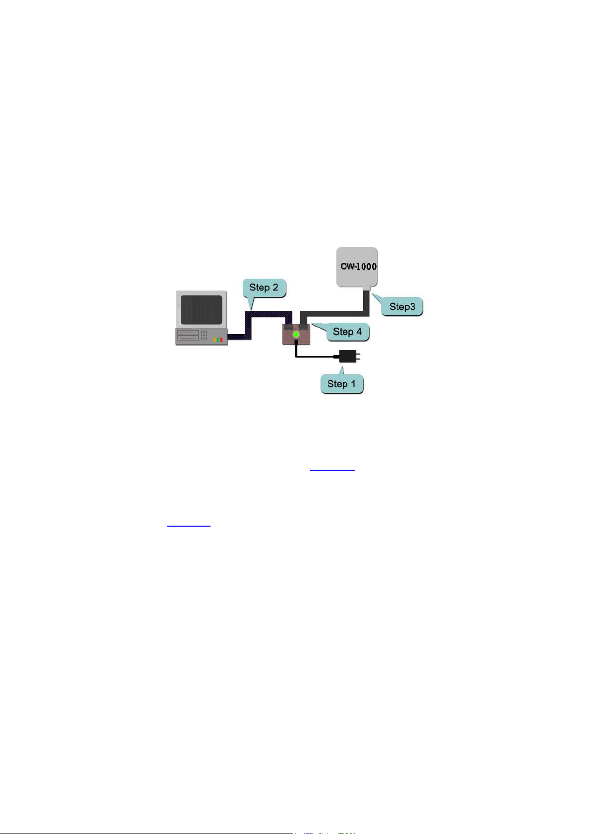
power up the OW-1000A. Refer to Figure 2-2 for steps 1 through 5.
Figure 2-2
Step1 : Connect the DC plug of the AC/DC power adapter into the DC
Input Port of Inline Power Injector and the wall-mount plug into a
power outlet or power strip (refer to page 6
). The Power LED on the
Inline Power Injector will light up.
Step2 : Run the cross-over type uplink Ethernet cable from Data Input
Port (refer topage 6
) to the Ethernet port on a PC.
Step3 : Connect the 30m CAT 5 Ethernet cable into the OW-1000A unit.
Hand tighten the connector.
Step4 : Connect the remaining end of the 30m CAT 5 cable into the PoE
labeled AP/Bridge. This is the power side of the PoE that will power up
the OW-1000A.
When the OW-1000A receives power over the Ethernet cable, the
OW-1000A will start its boot up sequence and the Active LED on the
Inline Power Injector will light up.
You can configure the OW-1000A via HTML browser, such as Microsoft
Internet Explorer or Netscape Navigator from a remote host or PC.
9
Page 10

2.4 Basic Configuration
2.4.1 Basic Configuration Steps
Note: All setting changing must Reboot the device after click
Apply
This section describes a two-step SYSTEM configuration procedure to
setup OW-1000A.
Step1 : Modify the factory-default parameters on the web page
“/Network/Network/”, a n d cl ic k APPLY to save the changes.
Step2 : Modify the factory-default parameters on the web page
“/WIRELESS/Wi-Fi 1”, an d cli ck APPLY to save the changes, than
click “/SYSTEM/Reboot/”Reboot to take effect on the previous
configuration changes.
2.4.2 Logging into the Web Interface
The OW-1000A supports access to the configuration system through the
use of an HTTP Interface.
ʇ Web Configuration
Before configuring OW-1000A, the user needs to know the IP Address
assigned to the unit. When shipped from the factory, the IP Address
192.168.1.1 was assigned to the OW-1000A by default. To start a web
connection, use http://192.168.1.1
ʇ Web Access Procedures
Once you identify the IP Address assigned to OW-1000A, use web
browser to configure OW-1000A through the HTTP Interface. The
following procedure explains how to configure each item.
Step1 : Open your browser and enter the IP Address
Step2 : Press <ENTER> key and the OW-1000A Login screen appears
as shown in Figure 2-3.
10
Page 11
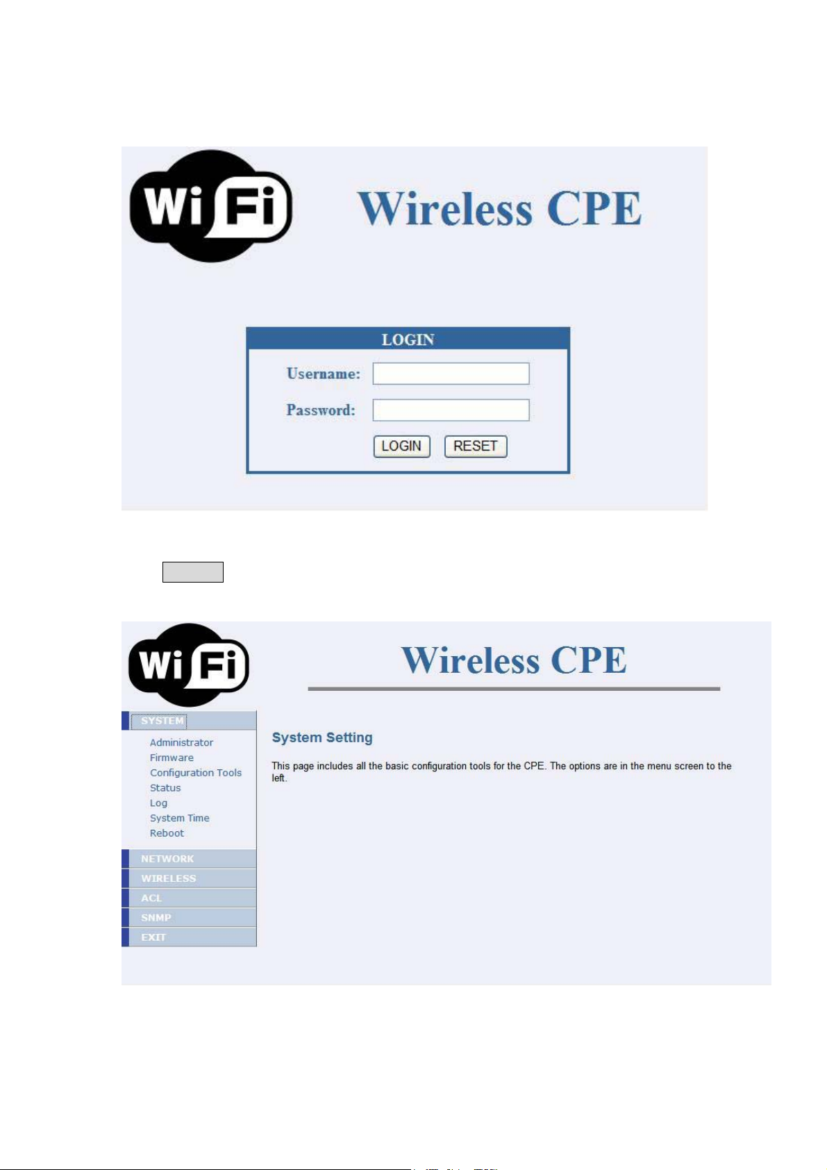
Figure 2-3
Step3 : Enter “admin”in the Username and Password fields, and
click LOGIN to enter the web configuration user interface screen as
shown below.
Figure 2-4
11
Page 12

ʇ Web Configuration Structure
The web configuration user interface shown above in Figure 2-5 is
grouped into a tree structure, and contains the following settings or
information.
ɏġ SYSTEM
Ʌġ Administrator
Ʌġ Firmware
Ʌġ Configuration
Ʌġ Status
Ʌġ Log
Ʌġ System Time
Ʌġ Reboot
ɏġ NETWORK
Ʌġ Network
Ʌġ HotSpot
ɏġ WIRELESS
Ʌġ Wi-fi 1
Ʌġ Wi-fi 2
Ʌġ Wi-fi 3
Ʌġ Wi-fi 4
ɏġ ACL
Ʌġ ACL for Wi-fi 1
Ʌġ ACL for Wi-fi 2
Ʌġ ACL for Wi-fi 3
Ʌġ ACL for Wi-fi 4
ɏġ SNMP
Ʌġ Agent Settings
ɏġ EXIT
Move through the tree by clicking on an icon to expand or collapse the
tree. The nodes on the tree represent web pages that allow viewing and
modifying the parameters.
12
Page 13
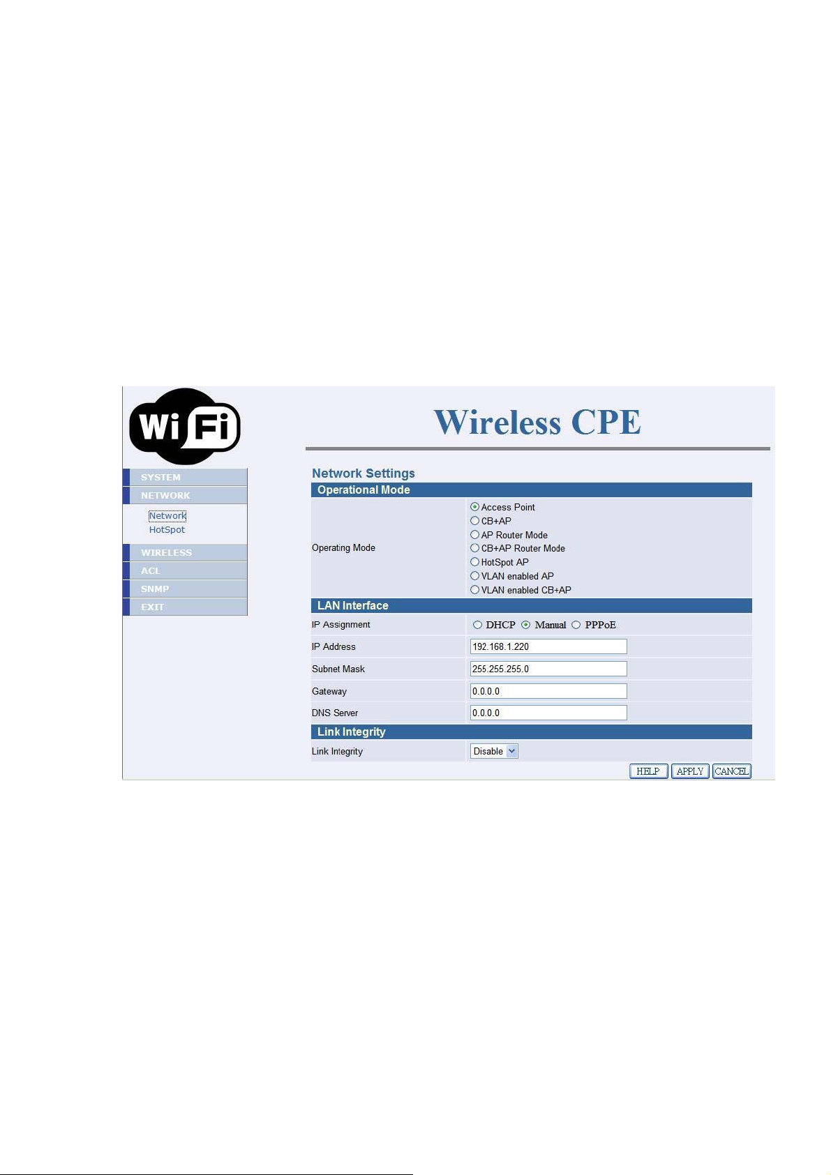
2.4.3 Set Operating Mode, IP Address, Subnet Mask, Default
Route IP, DNS Server IP of OW-1000A
ʇ LAN Settings
These are the settings of the LAN (Local Area Network) interface for the
Access Point. The Access Point's local network (LAN) settings are
configured based on the IP Address and Subnet Mask assigned in this
section. The IP address is also used to access this Web-based
management interface. This option is available in the “/NETWORK/
NETWORK /” page as shown in Figure 2-6.
Figure 2-6
ʇ Get LAN IP From
Choose "DHCP (Dynamic)" if your router supports DHCP and you want
the router to assign an IP address to the AP. In this case, you do not need
to fill in the following fields. Choose "Static IP (Manual)" if your router
does not support DHCP or if for any other reason you need to assign a
fixed address to the AP. In this case, you must also configure the
following fields.
13
Page 14

Note that you cannot choose "DHCP (Dynamic)" if you have enabled the
"DHCP Server" option on the DHCP page; the AP cannot be both a DHCP
client and a DHCP server.
ʇ IP Address
The IP address of the AP on the local area network. Assign any unused IP
address in the range of IP addresses available for the LAN.
For example, 192.168.1.1.
ʇ Subnet Mask
The subnet mask of the local area network.
ʇ Gateway
The IP address of the router on the local area network.
ʇ DNS Server
This entry is optional. Enter a DNS Server for the local network.
14
Page 15
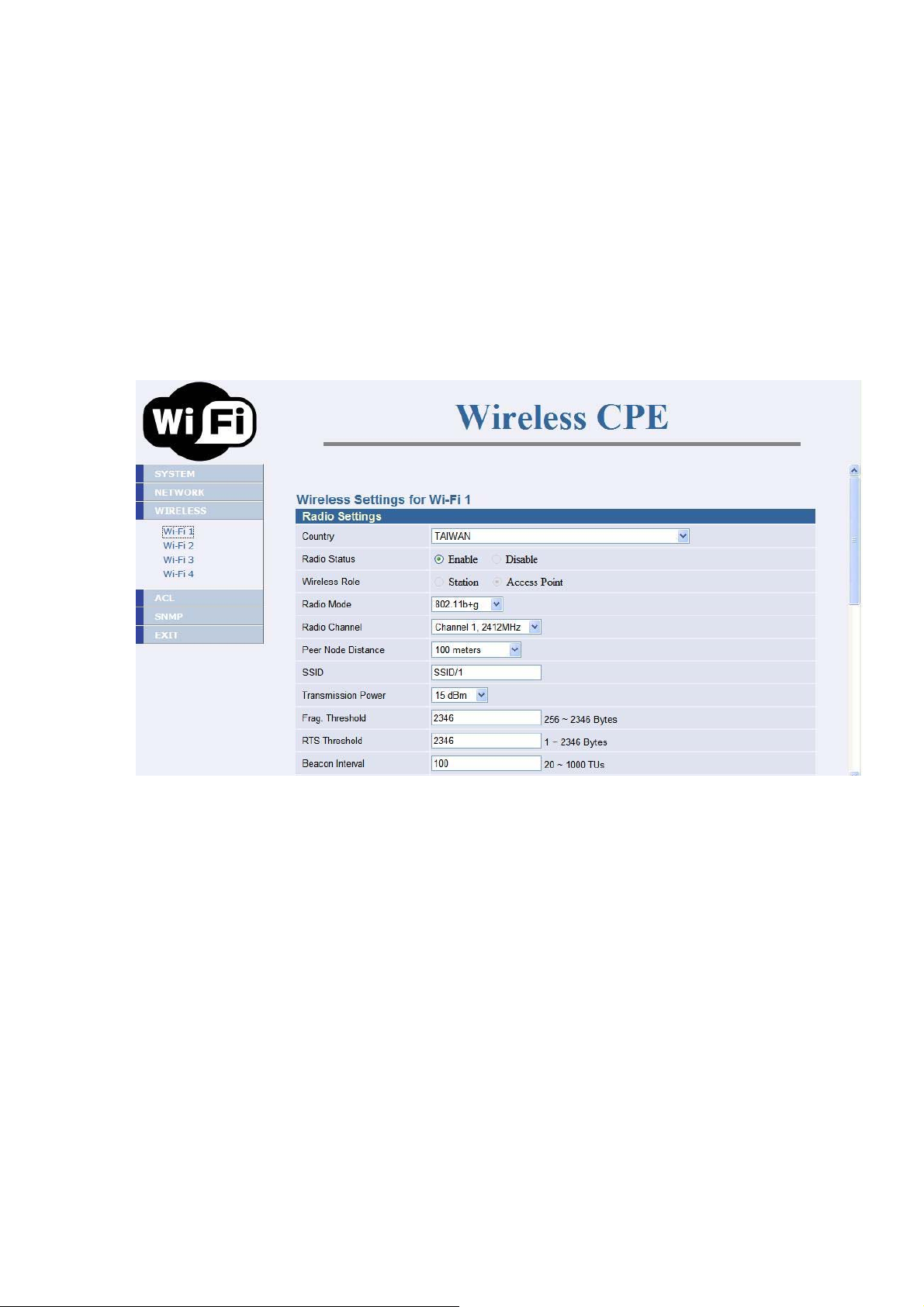
2.4.4 Set Wireless SSID for Wireless Interface
ʇ Wireless Network Name 炷Also called the SSID炸
When you are browsing for available wireless networks, this is the name
that will appear in the list (unless Visibility Status is set to Invisible, see
below). This name is also referred to as the SSID. For security purposes,
it is highly recommended to change from the pre-configured network
name. This option is available in the “/WIRELESS/Wi-Fi 1/” page as
shown in Figure 2-7
Figure 2-7
15
Page 16

2.4.5 Set Wireless Encryption for Wireless Interface
The OW-1000A supports 64-bit and 128-bit WEP encryption.
For 64-bit WEP encryption, an encryption key is 10 hexadecimal
characters (0-9 and A-F) or 5 ASCII characters.
For 128-bit WEP encryption, an encryption key is 26 hexadecimal
characters or 13 ASCII characters.
Modify the WEP encryption parameters on the web page
“/WIRELESS/Wi-Fi 1 SECURITY ”. Choice “WEP” Enter 1~15
characters into the WEP Key field, than click Apply 炻
“/SYSTEM/Reboot ”Reboot. page as shown in Figure 2-8
Figure 2-8
16
Page 17

2.4.6 Change Supervisor Account & Password
Enter the SYSTEM > Administrator page. Figure 2-9 below shows the
SYSTEM / Administrator page.
Figure 2-9
ʇ
ADMIN PASSWORD
Enter current password in the SYSTEM / Administrator / Password
Setting Current Password field. Enter new password in the
“PASSWORD and Re-type Password” field for changing new
password. Then and click APPLY and reboot the device.
17
Page 18

2.4.7 Upgrade the Firmware
ʇ Update the Firmware
Enter the SYSTEM > FIRMWARE page as shown in Figure 2-10 to
upgrade OW-1000A. Here, user must select which file you want to
upgrade it (Program image), then click APPLY button to start the
upgrade process.
Hint: It takes about 10 min, to complete the restart process.
Figure 2-10
Caution The Part 15 radio device operates on a non-interference basis with
other devices operating at this frequency when using integrated antennas. Any
changes or modification to the product not expressly approved by Original
Manufacture could void the user's authority to operate this device.
Caution
professionally installed
To meet regulatory restrictions and the safety of the installation, this product MUST be
. End user can’t install this device by themself
18
Page 19

Chapter 3. Network Topologies
This chapter describes several common types of installations
implemented by using the OW-1000A’s line of Outdoor Wireless System.
This is by no means intended to be an exhaustive list of all possible
configurations, but rather shows examples of some of the more common
implementations. The OW-1000A CB can be configured to function as a
Wireless Client Router or Bridge to a central access point like the
OW-1000A AP see Figure 3-1 below.
Figure 3-1
The OW-1000A CB performs in either router or bridge mode. In a
Point-to-Multipoint topology, all communication between network systems is done
through a centralized agent. Among the OW-1000A Outdoor Wireless Bridge
products, the centralized agent is Central Bridge (OW-1000A AP) and the individual
network notes may be Bridge (OW-1000A CB ).
To show the available Point-to-Multipoint topologies, the following examples are
provided.
19
Page 20

Wireless Client Bridge-to-Central Wireless Bridge
3.1 Wireless Client Bridge-to-Central Wireless Bridge
Figure 3-2
Refer to Figure 3-2 for the following setup.
Note:
The OW-1000A AP is the Central Wireless Bridge and OW-1000A
CB is the Wireless Client Bridge
Step 1 Set the OW-1000A AP to perform a bridge (bridge IP address:
192.168.1.1).
Step 2 Set Wireless parameters on the AP to: Channel (1) and SSID
(wireless)
Step 3 Set the OW-1000A CB to function in the bridge mode (bridge IP
address: 192.168.1.241).
Step 4 Set Wireless parameters on the OW-1000A CB to: Channel (1)
and SSID (wireless), and these parameters must be the same with
COU.
Step 5 Left side subnet is transparent to the right side.
Step 6 DHCP server assign IP address to PC1 and PC2
20
Page 21

Chapter 4. All function on Device
4.1 SYSTEM
4.1.1 Administrator
Administrator Settings
Use this menu to restrict management access based on a specific
password. The default password comes with the installation guide.
Please change this password as soon as possible, and store it in a safe
place. Passwords can contain from 3-12 alphanumeric characters, and
are case sensitive.
Figure 4-1
Administrator Time-out
The amount of time of inactivity allowed before the user proceeds next
action. The user needs to re-login if the idle time passes timeout.
Remote Management
By default, management access is only available to users on your local
network. However, you can also manage the Wireless CPE from a remote
host. Just check the Enable box and enter the IP address of an
administrator to this screen.
21
Page 22

4.1.2 Firmware
Figure 4-2
Firmware Update - TFTP
You can use TFTP to upgrade the firmware. The "firmware information"
displays current firmware version and firmware date. On the managed
computer, run the TFTP Server utility. And specify the folder in which the
firmware file resides. After running the TFTP server, enter the TFTP
server IP and the filename. Click APPLY to complete your change. At
the end of the upgrade, the Wireless CPE may not respond to commands
for as long as ten minute. This is normal behavior and do not turn off the
Wireless CPE during the time.
Firmware Update - FTP
You can use WEB to upgrade the firmware. The "firmware information"
displays current firmware version and firmware date. Enter FTP Server
IP , Type the correct firmware file path and file name on the File field.
Enter the current FTP Username and Password. Click on APPLY to
complete your change. At the end of the upgrade, the Wireless CPE may
not respond to commands for as long as ten minute. This is normal
behavior and do not turn off the Wireless CPE during the time.
22
Page 23

4.1.3 Configuration Tools
Figure 4-3
Restore Factory Defaults - Reset the CPE's configuration settings to
the factory default values. Check the "Restore Factory Default
Configuration" radio button then click on APPLY button.
Backup settings/Restore settings - Check the "Backup
settings/Restore settings" radio button then click on APPLY button.
Backup Settings - Press the "Backup Settings" button to save the
settings of this device to a file named "config.bin" on your PC.
Restore Settings - Restore the settings of this device to the backup
settings. Enter the path and name of the backup file then press the
"Restore Settings" button. You will be prompted to confirm the backup
restoration.
23
Page 24

4.1.4 Status
Figure 4-4
You can use the Status screen to see the connection status for the LAN
and Wireless LAN interfaces. It also displays system up time and
firmware version.
The following items are included in this screen:
SYSTEM INFORMATION - Displays MAC address, System time,
Current firmware version and operation mode.
LAN INFORMATION - Displays IP settings of LAN port, including IP
Address and Subnet Mask.
WIRELESS INFORMATION - Displays wireless information, including
SSID, channel, Security status, and RF output power.
SYSTEM INFORMATION - Displays the system up time, the Wireless
CPE's firmware version, and the serial number.
24
Page 25

4.1.5 Log
Figure 4-5
The Access Point automatically logs (records) events of possible interest
in its internal memory. If there is not enough internal memory for all
events, logs of older events are deleted, but logs of the latest events are
retained. The Logs option allows you to view the Access Point logs.
25
Page 26

4.1.6 System Time
Figure 4-6
The Time Configuration option allows you to configure, update, and
maintain the correct time on CPE's internal system clock. From this
section you can set the time zone that you are in and set the Time Server.
Time Configuration- Set the Date and Time Manually. If you do not
have the NTP Server option in effect, you can either manually set the
time for your Access Point here.
Note: If the Access Point loses power for any reason, it cannot keep its
clock running, and will not have the correct time when it is started again.
To maintain correct time for schedules and logs, you must enter the
correct time after you restart the Access Point.
26
Page 27

4.1.7 Reboot
Figure 4-7
Reset Wireless CPE. In the event that the Wireless CPE stops responding
correctly or in some way stops functioning, you can perform a reboot.
Your existing settings will not be changed. To perform the reset, click on
the Reboot button. You will be asked to confirm your decision.
27
Page 28

4.2 NETWORK
4.2.1 Network
4.2.1.1 Operating Mode-Access Point
IP Assignment
DHCP
Choose "DHCP (Dynamic)" if your router supports DHCP and you
want the rout er to assign an IP address to the AP. In this case, you
do not need to fill in the following fields.
Figure 4-8
Manual
Choose "Manual" if your router does not support DHCP or if for any
other reason you need to assign a fixed address to the AP. In this
case, you must also configure the following fields.
IP Address
The IP address of the AP on the local area network. Assign any
unused IP address in the range of IP addresses available for the
LAN. For example, 192.168.1.101.
Subnet Mask
28
Page 29

The subnet mask of the local area network.
Gateway
The IP address of the router on the local area network.
DNS Server
DNS 炷Domain Name System炸, Penetrates the DNS system, We
may look up its IP by machine domain name, Also may instead look
up its domain name by machine IP
This entry is optional. Enter a DNS Server for the local network.
Figure 4-9
29
Page 30

PPPoE
Choose "PPPoE" if your Internet support PPPoE Server .You need
keyin Username and Password to login PPPoE Server.
Figure 4-10
PPPoE
Choose "PPPoE" if your Internet support PPPoE Server .You need
keyin Username and Password to login PPPoE Server.
4.2.1.2 Operating Mode-Access Point
4.2.1.3 Operating Mode-CB+AP
4.2.1.4 Operating Mode-AP Router
4.2.1.5 Operating Mode- CB+AP Router
4.2.1.6 Operating Mode- Hot Spot
4.2.1.7 Operating Mode- VLAN enable AP
4.2.1.8 Operating Mode- VLAN enable CB+AP
30
Page 31

HotSpotȐCaptive Portal
ȑ
HotSpot: Enable/Disable captive portal function. Note, the CPE will
become router mode and ALL ssid in Access Point role after HotSpot
enabled.
Domain: Set domain name for hotspot.
Primary Radius: Set primary radius server for hotspot user
authentication.
Secondary Radius: Set backup radius server for hotspot user
authentication.
NAS ID: Set CPE's NAS ID in RADIUS frames.
Called Station Name: Set CPE's station name in RADIUS frames.
NAS Location: Set CPE's location name in RADIUS frames.
NAS Location ID: Set CPE's location ID in RADIUS frames.
UAM Server: The URL for hotspot user login.
UAM Secret: The encryption key between UAM server and CPE.
UAM Allowed List: IPs/Hostnames that hotspot can visit before login.
Figure 4-11
31
Page 32

4.3 WIRELESS
You can set the wireless releated setting here
Figure 4-12
32
Page 33

4.3.1 Wi-Fi 1
Wireless Settings
Radio Status: Enable/Disable SSID.
Wireless Role: This SSID will act as Station or Access Point. Note: only
first SSID can act as station.
Radio Mode: Set 11g, 11b or 11b+g mode.
Radio Channel: Select radio channel or use auto.
Peer Node Distance: Set distance between this CPE and it's adjacent.
SSID: Set (extended) service set ID, a.k.a. netwrok name.
Transmission Power: Set transmission power in dBm, Note: H/W may
not xmit power as high as you set, depends on H/W faculty.
VLAN Tagging ID: Set this SSID's VLAN tag when VLAN tagging
enabled.
Maximum Associated Stations: Restrict maximu number of
associated stations.
Layer 2 Isolation: Prevent packets exchange between associated
stations.
Frag. Threshold: Fragmentation threshold.
RTS Threshold: RTS threshold.
Beacon Interval: Beacon interval in TUs.
WMM Tx: Set WMM parameters for packet transmission.
WMM Station: Set WMM parameters that provide for station.
Security:
WEP: Set WEP key in hexdecimal
WPA-Personal: WPA with pre-shared key.
WPA/WPA2-Personal: WPA and WPA2 co-existance with pre-shared
key.
WPA-Enterprise: WPA, key provided by RADIUS server.
WPA/WPA2-Enterprise: WPA and WPA2 co-existance, key provided by
RADIUS server.
4.3.2 Wi-Fi 2
4.3.3 Wi-Fi 3
4.3.4 Wi-Fi 4
33
Page 34

4.4 ACL
You can set the access control releated setting here
Figure 4-13
4.4.1 ACL for Wi-Fi 1
Wireless MAC ACL
Wireless MAC ACL Status: Enable/Disable ACL by MAC address.
Add New MAC Address: Add a new MAC address to MAC table and in
active status.
MAC Table: Active, this MAC will be checked. Inactive, this MAC will
ignore for checking. Remove, remove this MAC from MAC table.
4.4.2 ACL for Wi-Fi 2
4.4.3 ACL for Wi-Fi 3
4.4.4 ACL for Wi-Fi 4
34
Page 35

4.5 SNMP
You can set the SNMP Community and SNMP Trap setting here
4.5.1 Agent Settings
SNMP Agent provides a simple protection. Access to the SNMP device is
controlled through community names. The community name can be
thought of as a password. If you don't have the correct community name,
you can't retrieve any data (get) or make any change (set). Multiple
SNMP managers may be organized in a specified community. You can
change your SNMP community settings on this screen. Check the
“Enable” check box to turn on SNMP daemon. Click APPLY to complete
your change.
Read Only Community: Specify the name of community for read only
access.
Read Write Community: Specify the name of community for read and
write access.
4.6 EXIT
Figure 4-14
35
Page 36

Chapter 5. Specifications
The OW1000APP Outdoor Wireless Multi-Client Bridge/Access
Point/WDS (wireless distribution system) operates seamlessly in the 2.4
GHz frequency supporting the IEEE 802.11b/802.11g wireless standards.
It's the best way to add wireless capability to your existing wired network,
or to add bandwidth to your existing wireless installation.
To secure your wireless connectivity, it can encrypt all wireless
transmissions through 64/128-bit WEP data encryption and also
supports WPA/WPA2炷Personal/Enterprise炸. A MAC address filter lets you
select exactly which stations should have access to your network. With
the Wireless Multi-Client Bridge/Access Point, you'll experience the best
wireless connectivity available today.
36
Page 37

Features
z High Speed Data Rate Up to 54Mbps
z Output Power up to 26dBmƲ2dBm
z IEEE 802.11b/g Compliant
z Access Point / CB+AP / AP Router / CB+AP Router / HotSpot AP / VLAN AP /
VLAN CB+AP
z WEP/WPA/WPA2/ IEEE 802.1x Authenticator support
z Dust tight and Watertight and Weatherproof (IP65)
z Wide temperature range and robust mechanical design
z Power-over-Ethernet (12V-24V)
Technical Specifications
Data Rates 1, 2, 5.5, 6, 9, 11, 12, 18, 24, 36, 48, 54 Mbps
Standards IEEE802.11b/g, IEEE802.1x, IEEE802.3,
IEEE802.3u
Compatibility IEEE 802.11g/ IEEE 802.11b
Power
Active Ethernet – 12 VDC/1A
Requirements
Regulation
FCC Part 15/UL, ETSI 300/328/CE
Certifications
RF Information Atheros BB/MAC/RF
Frequency Band
Media Access
Protocol
Modulation
Technology
2.400焍2.483.5 MHz
Carrier Sense Multiple Access with Collision
Avoidance (CSMA/CA)
Orthogonal Frequency Division Multiplexing (OFDM),
DBPSK @ 1Mbps,
DQPSK @2Mbps,
CCK @ 5.5 & 11Mbps,
BPSK @ 6 and 9 Mbps,
QPSK @ 12 and 18 Mbps,
16-QAM @ 24 and 36 Mbps,
64-QAM @ 48 and 54 Mbps
Operating Channels 11 for North America, 14 for Japan, 13 for Europe
Receive Sensitivity
-72dBm @ 54Mbps
(Typical)
Available transmit
power(Typical)
802.11b: 15dBm
802.11g : 16dBm
37
Page 38

g
RF Connector 1 SMA female connector for external antenna using
Networking
Ad-Hoc, Infrastructure
Topology
Operation Mode Access Point / CB+AP / AP Router / CB+AP Router /
HotSpot AP / VLAN AP / VLAN CB+AP
Interface One 10/100Mbps RJ-45 LAN Port , RS-232 Console
Security IEEE802.1x authenticator /RADIUS client
(EAPMD5/TLS/TTLS) support in AP mode WPA / Pre
Share KEY (PSK)/TKIP MAC address filtering Hide
SSID in beacons Layer 2 Isolation
IP
DHCP client/server/PPPoE
Auto-configuration
Management
Web-based configuration (HTTP)
Configuration
Firmware Upgrade Upgrade firmware via web browser
Physical Dimensions 190(L)mm * 116(W)mm * 65H)mm
Weight 300g
Environmental
Temperature Range
Humidity
(non-condensing)
Package Contents
-Operating: -10°C to 60°C (14°F to 140°F)
-Storage: -20°Cto 70°C (-4°F to 158°F)
5%~95% Typical
EW-7301APG unit
12V, 1A AC/DC adapter with wall-plu
power code
Inline Power Injector (PoE)
User’s manual CD-ROM
Wall mounting kit
38
Page 39

Chapter 6. Default Settings
6.1 SYSTEM
6.1.1 Administrator
Parameter Description Default Value
Hostname Wlancpe.lan
Current Password
Password
Re-type Password
Idle Time Out
Enable
IP address
6.1.2 Firmware
Parameter Description Default Value
Using TFTP
Using FTP
6.1.3 Configuration Tools
Parameter Description Default Value
Restore Factory
0.0.0.0
30
Default
Configuration
Backup Settings /
Restore Settings
6.1.4 Status
39
Page 40

6.1.5 Log
6.1.6 System Time
Parameter Description Default Value
Setting by
Synchronize with an
Internet Time Server
Year / Month / Day 07/8/20
Hour : Minute :
02:26:06
Second
Hours from UTC +8
Server IP
NTP Server for
Reference
pool.ntp.org
pool.ntp.org or
129.132.2.21
Time Update for
0/0/0
Every
6.1.7 Reboot
40
Page 41

6.2 NETWORK
6.2.1 Network
Parameter Description Default Value
Operating Access Point
IP Assignment Manual
IP Address
192.168.1.1
Subnet Mask 255.255.255.0
Gateway
DNS Server
Link Integrity
0.0.0.0
0.0.0.0
Disable
PPPoE Username
PPPoE Password
6.2.2 Hotspot
Parameter Description Default Value
Domain Access Point
Primary Radius 192.168.10.80 1812
Secondary Radius
192.168.10.80 1813
Radius Shared
Secret
NAS ID
Called Station
Name
NAS Location
NAS Location ID
UAM URL
UAM Secret
UAM Allowed List
TypeYourRadiusSecre
tHere
isocc=tw,cc=886,ac=
4,network=hotspot
Typ eYo urU amS ecr et H
ere
www.paypal.com,ww
w.google.com
41
Page 42

6.3 WIRELESS
6.3.1 Wi-Fi 1
Parameter Description Default Value
Country
Radio Status
Wireless Role
Radio Mode
Radio Channel
Peer Node Distance
SSID
Transmission Power
Frag. Threshold
RTS Threshold
Beacon Interval
DTIM Interval
Wireless Security
VLAN Tagging ID
Layer2 Isolation
TAIWAN
Enable
Access Point
802.11b+g
Channel 1, 2412MHz
100 meters
SSID/1
15dBm
2346
2346
100
1
None
1
Enable
Maximum Associated
Stations
WMM Tx - Best Effort
WMM Tx -
Background
WMM Tx - Video
WMM Tx - Voice
WMM Station - Best
Effort
WMM Station -
Background
WMM Station – Video
WMM Station - Voice
32
7 1023 2 0.0
15 1023 7 0.0
3 7 1 1.5
7 15 1 3.0
7 1023 2 2048 Optional
15 1023 7 32 Optional
3 7 1 1504 Optional
7 15 1 3008 Optional
42
Page 43

6.3.2 Wi-Fi 2
Parameter Description Default Value
Country
Radio Status
Wireless Role
Radio Mode
Radio Channel
Peer Node Distance
SSID
Transmission Power
Frag. Threshold
RTS Threshold
Beacon Interval
DTIM Interval
Wireless Security
VLAN Tagging ID
Layer2 Isolation
TAIWAN
Enable
Access Point
802.11b+g
Channel 1, 2412MHz
100 meters
SSID/2
15dBm
2346
2346
100
1
None
2
Enable
Maximum Associated
Stations
WMM Tx - Best Effort
WMM Tx -
Background
WMM Tx - Video
WMM Tx - Voice
WMM Station - Best
Effort
WMM Station -
Background
WMM Station – Video
WMM Station - Voice
32
7 1023 2 0.0
15 1023 7 0.0
3 7 1 1.5
7 15 1 3.0
7 1023 2 2048 Optional
15 1023 7 32 Optional
3 7 1 1504 Optional
7 15 1 3008 Optional
43
Page 44

6.3.3 Wi-Fi 3
Parameter Description Default Value
Country
Radio Status
Wireless Role
Radio Mode
Radio Channel
Peer Node Distance
SSID
Transmission Power
Frag. Threshold
RTS Threshold
Beacon Interval
DTIM Interval
Wireless Security
VLAN Tagging ID
Layer2 Isolation
TAIWAN
Enable
Access Point
802.11b+g
Channel 1, 2412MHz
100 meters
SSID/3
15dBm
2346
2346
100
1
None
3
Enable
Maximum Associated
Stations
WMM Tx - Best Effort
WMM Tx -
Background
WMM Tx - Video
WMM Tx - Voice
WMM Station - Best
Effort
WMM Station -
Background
WMM Station – Video
WMM Station - Voice
32
7 1023 2 0.0
15 1023 7 0.0
3 7 1 1.5
7 15 1 3.0
7 1023 2 2048 Optional
15 1023 7 32 Optional
3 7 1 1504 Optional
7 15 1 3008 Optional
44
Page 45

6.3.4 Wi-Fi 4
Parameter Description Default Value
Country
Radio Status
Wireless Role
Radio Mode
Radio Channel
Peer Node Distance
SSID
Transmission Power
Frag. Threshold
RTS Threshold
Beacon Interval
DTIM Interval
Wireless Security
VLAN Tagging ID
Layer2 Isolation
TAIWAN
Enable
Access Point
802.11b+g
Channel 1, 2412MHz
100 meters
SSID/4
15dBm
2346
2346
100
1
None
4
Enable
Maximum Associated
Stations
WMM Tx - Best Effort
WMM Tx -
Background
WMM Tx - Video
WMM Tx - Voice
WMM Station - Best
Effort
WMM Station -
Background
WMM Station – Video
WMM Station - Voice
32
7 1023 2 0.0
15 1023 7 0.0
3 7 1 1.5
7 15 1 3.0
7 1023 2 2048 Optional
15 1023 7 32 Optional
3 7 1 1504 Optional
7 15 1 3008 Optional
45
Page 46

g
g
6.4 ACL
6.4.1 ACL for Wi-Fi
Parameter Description Default Value
Wireless MAC ACL Status Disable
Add New MAC Address 00:00:00:00:00:00
Wireless On/Off Schedulin
Disabled
Status
Scheduling on Sunday 0 24
Scheduling on Monday
Scheduling on Tuesday
Scheduling on Wednesday
Scheduling on Thursday
Scheduling on Friday
Scheduling on Saturday
0 24
0 24
0 24
0 24
0 24
0 24
6.4.2 ACL for Wi-Fi 2
Parameter Description Default Value
Wireless MAC ACL Status Disable
Add New MAC Address 00:00:00:00:00:00
Wireless On/Off Schedulin
Disabled
Status
Scheduling on Sunday 0 24
Scheduling on Monday
Scheduling on Tuesday
Scheduling on Wednesday
Scheduling on Thursday
Scheduling on Friday
Scheduling on Saturday
46
0 24
0 24
0 24
0 24
0 24
0 24
Page 47

g
g
6.4.3 ACL for Wi-Fi 3
Parameter Description Default Value
Wireless MAC ACL Status Disable
Add New MAC Address 00:00:00:00:00:00
Wireless On/Off Schedulin
Disabled
Status
Scheduling on Sunday 0 24
Scheduling on Monday
Scheduling on Tuesday
Scheduling on Wednesday
Scheduling on Thursday
Scheduling on Friday
Scheduling on Saturday
0 24
0 24
0 24
0 24
0 24
0 24
6.4.4 ACL for Wi-Fi 4
Parameter Description Default Value
Wireless MAC ACL Status Disable
Add New MAC Address 00:00:00:00:00:00
Wireless On/Off Schedulin
Disabled
Status
Scheduling on Sunday 0 24
Scheduling on Monday
Scheduling on Tuesday
Scheduling on Wednesday
Scheduling on Thursday
Scheduling on Friday
Scheduling on Saturday
0 24
0 24
0 24
0 24
0 24
0 24
47
Page 48

6.5 SNMP
Parameter Description Default Value
Agent Status Enable
System Location You know where it is.
System Contact
That is you.
System Name Wireless CPE
System
This is a wireless CPE
Description
Read Only
public
Community
Read Write
public
Community
6.6 EXIT
48
Page 49

Chapter 7. Regulatory Compliance Information
Federal Communication Commission Interference Statement
This equipment has been tested and found to comply with the limits for a Class B
digital device, pursuant to Part 15 of the FCC Rules. These limits are designed to
provide reasonable protection against harmful interference in a residential
installation. This equipment generates, uses and can radiate radio frequency
energy and, if not installed and used in accordance with the instructions, may cause
harmful interference to radio communications. However, there is no guarantee that
interference will not occur in a particular installation. If this equipment does cause
harmful interference to radio or television reception, which can be determined by
turning the equipment off and on, the user is encouraged to try to correct the
interference by one of the following measures:
- Reorient or relocate the receiving antenna.
- Increase the separation between the equipment and receiver.
- Connect the equipment into an outlet on a circuit different from that
to which the receiver is connected.
- Consult the dealer or an experienced radio/TV technician for help.
This device complies with Part 15 of the FCC Rules. Operation is subject to the
following two conditions: (1) This device may not cause harmful interference, and (2)
this device must accept any interference received, including interference that may
cause undesired operation.
FCC Caution: Any changes or modifications not expressly approved by the party
responsible for compliance could void the user's authority to operate this equipment.
IMPORTANT NOTE:
FCC Radiation Exposure Statement:
This equipment complies with FCC radiation exposure limits set forth for an
uncontrolled environment. This equipment should be installed and operated with
minimum distance 20cm between the radiator & your body.
This transmitter must not be co-located or operating in conjunction with any other antenna
Caution
professionally installed
To meet regulatory restrictions and the safety of the installation, this product MUST be
. End user can’t install this device by themself
49
Page 50

Antenna type Antenna Gain
Patch 9dBi
50
 Loading...