


OW-1000
Outdoor Wireless Access Point
User’s Manual
B
EFORE INSTALLING THE UNIT, PLEASE READ THIS MANUAL THOROUGHLY, AND RETAIN IT FOR
FUTURE REFERENCE
1
.

► Contents
Chapter 1. Introduction................................................................................................................3
1.1 Introducing the OW-1000..............................................................................................3
1.2 Product Features............................................................................................................3
1.3 Package Contents...........................................................................................................3
1.4 System Requirements ....................................................................................................4
1.5 Inline Power Injector (PoE)..........................................................................................4
Chapter 2. Installation and Basic Configuration.......................................................................5
2.1 Before You Start .............................................................................................................5
2.2 Locate the OW-1000 and Inline Power Injector Ports...............................................6
2.3 Preparing Installation....................................................................................................8
2.4 Basic Configuration.......................................................................................................9
2.4.1 Basic Configuration Steps....................................................................9
2.4.2 Logging into the Web Interface.......................................................9
2.4.3 Set Operating Mode, IP Address, Subnet Mask, Default
Route IP, DNS Server IP of OW-1000.........................................................12
2.4.4 Set Wireless SSID for Wireless Interface ................................14
2.4.5 Set Wireless Encryption for Wireless Interface ...................15
2.4.6 Change Supervisor Account & Password..................................16
2.4.7 Upgrade the Firmware.........................................................................17
2

Chapter 1. Introduction
1.1 Introducing the OW-1000
The OW-1000 is fully interoperable with IEEE 802.11b/g compliant Outdoor
Wireless Last-mile product. The OW-1000 oper ates in AP mode or remote bridge
mode, and connects to OW-1000 AP/CB to construct point-to-point as well as
point-to-multipoint topologies, for maximum flexibility in configuring
building-to-building networks and WISP functions.
1.2 Product Features
Outdoor enclosure in compliance with versatile industrial IP(Ingress
Protection) level covering IP67, IP66, IP55 and IP50
RF transmit power 802.11b mode @ 11Mbps data rate
RF transmit power 802.11g mode @ 54Mbps data rate
Embedded 9dBi patch directional antenna
Support 48VDC 0.375A Power-over-Ethernet(PoE)
NAT/NAPT and Virtual Server Mapping support (Optional / RB only)
MIB-I support
MAC address based access control
Hint: IP(Ingress Protection)
1.3 Package Contents
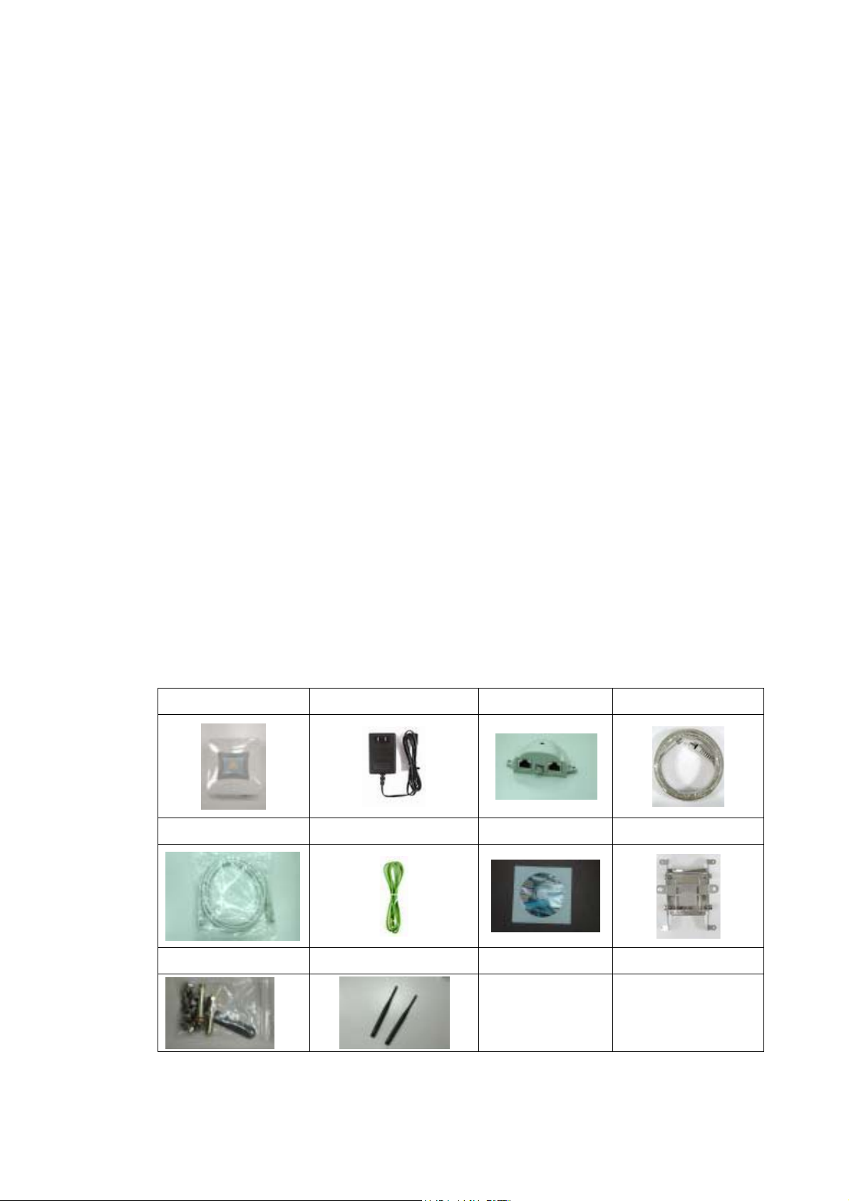
The product package contains the following items.
1. One (1) OW-1000 Outdoor Wireless Access Point / Client Bridge unit
2. One (1) 100~240VAC, 50~60Hz AC to 48V/0.375A DC switching adapter
3. One (1) 48VDC, 0.375A Inline Power Injector (PoE)
4. One (1) 30m RJ-45 CAT-5 Ethernet cable
5. One (1) 1.8m RJ-45 CAT-5 Cross Over Cable
6. One (1) 1.8m grounding wire (Optional)
7. One (1) User manual CD-disc
8. One (1) wall/mast mounting kit
9. One (1) band clamp
3

1.4 System Requirements
Installation of the OW-1000 Outdoor Wireless Access Point/Client Bridge requir es
the following:
1. A Windows-based PC/AT compatible computer(PC system requirement:better
than PIII 800 or other 100% compatible equipment , OS:windows 2000/XP)
or Ethernet
data device with an available RJ-45 Ethernet port to run the
configuration program or with TCP/IP connection to the Ethernet
network.
2. A 10/100Base-T Ethernet RJ-45 Ethernet cable is connected to Ethernet
network.
3. An AC power outlet (100~240V, 50~60Hz) supplies the power.
1.5 Inline Power Injector (PoE)
The OW-1000 is equipped with an Inline Power Injector module. The Inline P ower
Injector (PoE) delivers both data and power to OW-1000 unit via a signal
Ethernet cable, and gives the following benefits to improve the performance vs.
installation cost ratio.
This works great in areas where you may not have power , like house
roof.
This also allows you to place the OW-1000 unit closer to the antenna, to
make installation easier more thus reducing signal loss over antenna
cabling.
Ethernet signal travels well over CA T 5 cable but 2.4GHz signal doesn't
do as well over antenna cabling.
Ethernet cabling is much cheaper than Antenna cabling.
4
Chapter 2. Installation and Basic Configuration
This chapter describes the procedures of installing the OW-1000.
2.1 Before You Start
After unpacking the system, make sure the following items are present and in
good condition. Refer to below pictures for product image.
1. OW-1000 Outdoor Wireless Access Point/Client Bridge unit
2. 100~240VAC, 50~60Hz AC to 48V/0.375A DC switching adapter
3. Inline Power Injector (PoE) 48VDC, 0.375A
4. RJ-45 CAT-5 Ethernet cable 30 m
5. RJ-45 CAT-5 Cross-over Ethernet cable 1.8m
6. Grounding wire 1.8m
7. User manual CD-disc
8. Wall/mast mounting kit, including one (1) band clamp
9. Screws
10. 5dBi Oimi-type Antenna (for AP) ,if panel antenna(for CB), it must be
installed into Unit.
1. Unit 2. Adapter 3. PoE 4. 30m cable
5. 1.8m cable 6. Grounding wire 7. CD 8. Wall mount
9. Screws 10. Antenna(for AP)
5
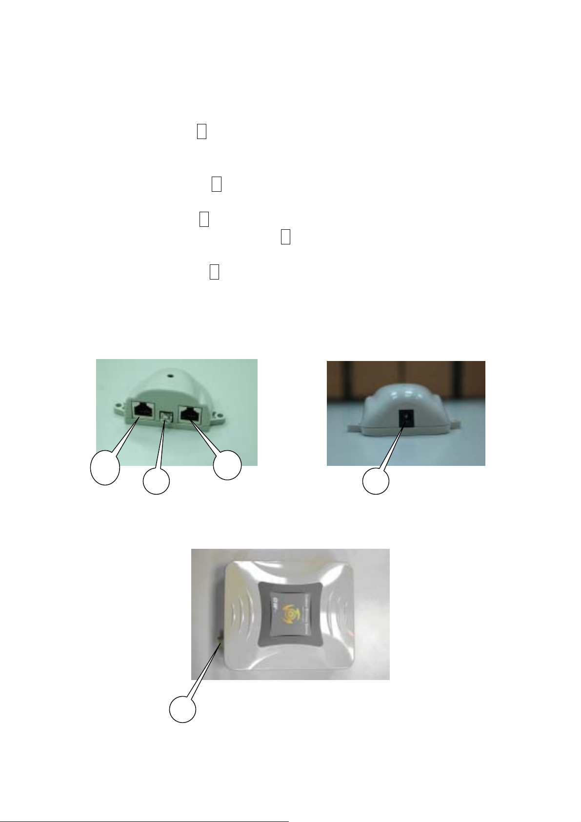
2.2 Locate the OW-1000 and Inline Power Injector Ports
3
5
► Interface on the OW-1000 Unit
Ethernet Port 1 : for connecting the 30m RJ-45 CAT-5 Ethernet cable.
► Interface on the Inline Power Injector
Data Input Port 2 : for connecting cross-over Ethernet Cable to PC or
straight Ethernet cable to Hub Switch Router .
DC Input Port 3 : power adapter 48V, 0.375A DC input.
Power & Data Output Port 4 : for connecting the 30m RJ-45 CAT-5
Ethernet Cable.
Grounding Port 5 : for connecting grounding wire.
Device
4
2
POE picture1 POE picture2
1
Figure 2-1
Power and Data Interface location on the PoE denoted by numbers 1-6.
6

► Mount OW-1000 on A Wall/Mast
The OW-1000 can be mounted on the wall, you can use the Wall Mount kit to
mount the OW-1000 as shown in Figure 2-2.
Figure 2-2
You can also mount the OW-1000 to the mast as shown in Figure 2-3.
Figure 2-3
7

2.3 Preparing Installation
Before installing OW-1000 for outdoor application or hard-to-reach location, we
recommend configuring and test all the devices first.
For configuring the OW-1000, please follow the quick steps below to power up the
OW-1000. Refer to Figure 2-4 for steps 1 through 5.
Figure 2-4
Step1 : Connect the DC plug of the AC/DC power adapter into the DC Input Port
of Inline Power Injector and the wall-mount plug into a power outlet or power
strip (refer to page 6). The Power LED on the Inline P ower Injector will light up.
Step2 : Run the cross-over type uplink Ethernet cable from Data Input Port
(refer topage 6
) to the Ethernet port on a PC.
Step3 : Connect the 30m CAT 5 Ethernet cable into the OW-1000 unit. Hand
tighten the connector.
Step4 : Connect the remaining end of the 30m CAT 5 cable into the P oE labeled
AP/Bridge. This is the power side of the PoE that will power up the OW-1000.
When the OW-1000 receives power over the Ethernet cable, the OW-1000 will
start its boot up sequence and the Active LED on the Inline Power Injector will
light up.
You can configure the OW-1000 via HTML browser, such as Microsoft Internet
Explorer or Netscape Navigator from a remote host or PC.
8

2.4 Basic Configuration
2.4.1 Basic Configuration Steps
This section describes a two-step BASIC configuration procedure to setup
OW-1000.
Step1 : Modify the factory-default parameters on the web page “/ BASIC/LAN/”,
and click Save Settings to save the changes, than click Continue .
Step2 : Modify the factory-default para meters on the web page
“/BASIC/Wireless/”, and click Save Settings to save the changes, than click
Reboot the Device to take effect on the previous configuration changes.
2.4.2 Logging into the Web Interface
The OW-1000 supports access to the configuration system through the use of an
HTTP Interface.
► Web Configuration
Before configuring OW-1000, the user needs to know the IP Address assigned to
the unit. When shipped from the factory, the IP Address 192.168.1.1 was
assigned to the OW-1000 by default. To start a web connection, use
http://192.168.1.1
► Web Access Procedures
Once you identify the IP Address assigned to OW-1000, use web browser to
configure OW-1000 through the HTTP Interface. The following procedure
explains how to configure each item.
Step1 : Open your browser and enter the IP Address
Step2 : Press <ENTER> key and the OW-1000 Login screen appears as shown
in Figure 2-5.
9

Figure 2-5
Step3 : Enter “admin” in the Username and Password fields, and click Log In
to enter the web configuration user interface screen as shown below.
Figure 2-6
► Web Configuration Structure
The web configuration user interface shown above in Figure 2-6 is grouped into
a tree structure, and contains the following settings or information.
10

▽ SYSTEM
● Administrator
● Firmware
● Configuration
● Status
● Log
● System Time
● Reboot
▽ NETWORK
● Network
▽ WIRELESS
● Access Control
● Wi-fi 1
● Wi-fi 2
● Wi-fi 3
● Wi-fi 4
● Wi-fi 5
● Wi-fi 6
● Wi-fi 7
● Wi-fi 8
● Wi-fi 9
● Wi-fi 10
▽ SNMP
● Agent Settings
▽ EXIT
Move through the tree by clicking on an icon to expand or collapse the tree. The
nodes on the tree represent web pages that allow viewing and modifying the
parameters.
11

2.4.3 Set Operating Mode, IP Address, Subnet Mask, Default Ro ute IP,
DNS Server IP of OW-1000
► LAN Settings
These are the settings of the LAN (Local Area Network) interface for the Access
Point. The Access Point's local network (LAN) settings are configured based on
the IP Address and Subnet Mask assigned in this section. The IP address is also
used to access this Web-based management interface. This option is available in
the “/NETWORK/ NETWORK /” page as shown in Figure 2-7.
Figure 2-7
► Get LAN IP From
Choose "DHCP (Dynamic)" if your router supports DHCP and you want the router
to assign an IP address to the AP. In this case, you do not need to fill in the
following fields. Choose "Static IP (Manual)" if your router does not support DHCP
or if for any other reason you need to assign a fixed address to the AP. In this
case, you must also configure the following fields.
Note that you cannot choose "DHCP (Dynamic)" if you have enabled the "DHCP
Server" option on the DHCP page; the AP cannot be both a DHCP client and a
DHCP server.
12

► IP Address
The IP address of the AP on the local area network. Assign any unused IP address
in the range of IP addresses available for the LAN. For example, 192.168.1.1.
► Subnet Mask
The subnet mask of the local area network.
► Gateway
The IP address of the router on the local area network.
► DNS Server
This entry is optional. Enter a DNS Server for the local network.
13

2.4.4 Set Wireless SSID for Wireless Interface
► Wireless Network Name (Also called the SSID)
When you are browsing for available wireless networks, this is the name that will
appear in the list (unless Visibility Status is set to Invisible, see below). This
name is also referred to as the SSID. For security purposes, it is highly
recommended to change from the pre-configured network name. This option is
available in the “/WIRELESS/Wi-Fi 1/” page as shown in Figure 2-8.(Note :
“Radio Channel” only supports channel 1 to channel 11. Even “Auto Select”, it
only auto-select the channel between channel 1 to channel 11 )
Figure 2-8
14

2.4.5 Set Wireless Encryption for Wireless Interface
The OW-1000 supports 64-bit and 128-bit WEP encryption.
For 64-bit WEP encryption, an encryption key is 10 hexadecimal characters (0-9
and A-F) or 5 ASCII characters.
For 128-bit WEP encryption, an encryption key is 26 hexadecimal char acters or
13 ASCII characters.
Modify the WEP encryption parameters on the web page “/WIRELESS/Wi-Fi 1/
Security ”. Choice “WEP” Enter 1~15 characters into the WEP Key field, than
click Apply ,“/SYSTEM/Reboot ”Reboot. page as shown in Figure 2-9
Figure 2-9
15

2.4.6 Change Supervisor Account & Password
Enter the SYSTEM > Administrator page. Figure 2-10 below shows the
SYSTEM / Administrator page.
Figure 2-10
ADMIN PASSWORD
►
Key in current password in the SYSTEM / Administrator / Password Setting
Current Password field. Change the ADMIN PASSWORD’s password in the
SYSTEM / Administrator Password Setting Password and Re-type
Password fields, and click APPLY ,than,“/SYSTEM/Reboot ”Reboot.
16

2.4.7 Upgrade the Firmware
► Update the Firmware
Enter the SYSTEM > FIRMWARE page as shown in Figure 2-11 to upgrade
OW-1000. Here, user must select which file you want to upgrade it (Program
image), then click APPLY button to start the upgrade process.
Hint: It takes about 15 min, to complete the restart process.
Figure 2-11
Caution The Part 15 radio device operates on a non-interf e rence basis with
other devices operating at this frequency when using integrated antennas.
Any changes or modification to the product not expressly approved by
Original Manufacture could void the user's authority to operate this device.
Caution To meet regulatory restrictions and the safety of the installation, this product MUST be
professionally installed
. End user can’t install this device by themselves.
17
 Loading...