

Page 1

Outdoor Wireless Access Point
OW-2000
User’s Manual
B
EFORE INSTALLING THE UNIT, PLEASE READ THIS MANUAL THOROUGHLY, AND RETAIN
IT FOR FUTURE REFERENCE
.
1
Page 2

► Contents
Chapter 1. Introduction............................................................................................... 4
1.1 Introducing the OW-2000......................................................................... 4
1.2 Product Features....................................................................................... 4
1.3 Package Contents...................................................................................... 4
1.4 System Requirements...............................................................................5
1.5 Inline Power Injector (PoE)..................................................................... 5
Chapter 2. Installation and Basic Configuration......................................................6
2.1 Before You Start........................................................................................6
2.2 Locate the OW-2000 and Inline Power Injector Ports..........................7
2.3 Preparing Installation............................................................................... 9
2.4 Basic Configuration................................................................................10
2.4.1 Basic Configuration Steps ................................................. 10
2.4.2 Logging into the Web Interface..................................... 10
2.4.3 Set Operating Mode, IP Address, Subnet Mask,
Default Route IP, DNS Server IP of OW-2000...................... 13
2.4.4 Set Wireless SSID for Wireless Interface................ 15
2.4.5 Set Wireless Encryption for Wireless Interface... 16
2.4.6 Change Supervisor Account & Password ................. 17
2.4.7 Upgrade the Firmware......................................................... 18
Chapter 3. Network Topologies.................................................................................19
3.1 Wireless Client Bridge-to-Central Wireless Bridge.............................20
Chapter 4. All function on Device............................................................................. 21
4.1 BASIC ...................................................................................................... 21
4.1.1 Wizard ........................................................................................... 21
4.1.2 LAN.................................................................................................. 23
4.1.3 DHCP............................................................................................... 25
4.1.4 WIRELESS.................................................................................... 30
4.2 ADVANCED............................................................................................ 35
4.2.1 MAC Address Filter................................................................. 35
4.2.2 Advance Wireless ................................................................... 37
4.3 TOOLS..................................................................................................... 39
4.3.1 Admin.............................................................................................39
4.3.2 Time................................................................................................ 42
4.3.3 System........................................................................................... 44
4.3.4 Firmware...................................................................................... 45
4.4 Status........................................................................................................ 47
4.4.1 Device Info ................................................................................. 47
4.4.2 Logs................................................................................................. 49
4.4.3 Statistics...................................................................................... 51
Chapter 5. Specifications........................................................................................... 53
Chapter 6. Default Settings ....................................................................................... 56
6.1 BASIC ...................................................................................................... 56
2
Page 3

6.1.1 WIZARD........................................................................................ 56
6.1.2 LAN.................................................................................................. 57
6.1.3 DHCP............................................................................................... 57
6.1.4 WIRELESS.................................................................................... 58
6.2 ADVANCE............................................................................................... 59
6.2.1 MAC Address Filter............................................................................ 59
6.2.2 Advanced Wireless..............................................................................59
6.3 TOOLS..................................................................................................... 59
6.3.1 ADMIN................................................................................................. 59
6.3.2 TIME.................................................................................................... 60
6.3.3 SYSTEM.............................................................................................. 60
6.3.4 FIRMWARE........................................................................................ 60
3
Page 4

Chapter 1. Introduction
1.1 Introducing the OW-2000
The OW-2000 is fully interoperable with IEEE 802.11a and/or 802.11b/g
compliant Outdoor Wireless Last-mile product. The OW-2000 oper ates in
AP mode or remote bridge mode, and connects to OW-2000 AP/CB to
construct point-to-point as well as point-to-multipoint topologies, for
maximum flexibility in configuring building-to-building networks and
WISP functions.
1.2 Product Features
¾ Outdoor enclosure in compliance with versatile industrial IP
(Ingress Protection) level covering IP67, IP66, IP55 and IP50
¾ RF transmit power 802.11b mode @ 11Mbps data rate
¾ RF transmit power 802.11g mode @ 54Mbps data rate
¾ Embedded 9dBi patch directional antenna
¾ Support 48VDC 0.375A Power-over-Ethernet(PoE)
¾ NAT/NAPT and Virtual Server Mapping support (Optional / RB
only)
¾ MIB-I support
¾ MAC address based access control
Hint: IP(Ingress Protection)
1.3 Package Contents
The product package contains the following items.
1. One (1) OW -2000 Outdoor Wireless Access Point / Client Bridge
unit
2. One (1) 100~240VAC, 50~60Hz AC to 48V/0.375A DC switching
adapter
3. One (1) 48VDC, 0.375A Inline Power Injector (PoE)
4. One (1) 30m RJ-45 CAT-5 Ethernet cable
5. One (1) 1.8m RJ-45 CAT-5 Cross Over Cable
6. One (1) 1.8m grounding wire (Optional)
7. One (1) User manual CD-disc
8. One (1) wall/mast mounting kit
9. One (1) band clamp
4
Page 5

1.4 System Requirements
Installation of the OW-2000 Outdoor Wireless Access Point/Client Bridge
requires the following:
1. A Windows-based PC/AT compatible computer ( PC system
requirement:better than PIII 800 or other 100% compatible equipment , OS:
windows 2000/XP ) or Ethernet data device with an available
RJ-45 Ethernet port to run the configuration program or with
TCP/IP connection to the Ethernet network.
2. A 10/100Base-T Ethernet RJ-45 Ethernet cable is connected to
Ethernet network.
3. An AC power outlet (100~240V, 50~60Hz) supplies the power.
1.5 Inline Power Injector (PoE)
The OW-2000 is equipped with an Inline Power Injector module. The
Inline Power Injector (PoE) delivers both data and power to OW-2000
unit via a signal Ethernet cable, and gives the following benefits to
improve the performance vs. installation cost ratio.
¾ This works great in areas where you may not ha ve power , like
house roof.
¾ This also allows you to place the OW-2000 unit closer to the
antenna, to make installation easier more thus reducing signal
loss over antenna cabling.
¾ Ethernet signal travels well ov er CA T 5 cable but 2.4GHz signal
doesn't do as well over antenna cabling.
¾ Ethernet cabling is much cheaper than Antenna cabling.
5
Page 6
Chapter 2. Installation and Basic Configuration
This chapter describes the procedures of installing the OW-2000.
2.1 Before You Start
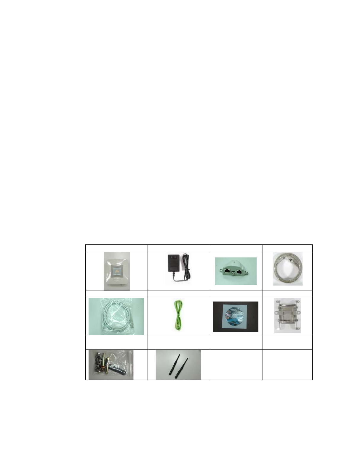
After unpacking the system, make sure the following items are present
and in good condition. Refer to below pictures for product image.
1. OW-2000 Outdoor Wireless Access Point/Client Bridge unit
2. 100~240VAC, 50~60Hz AC to 48V/0.375A DC switching
adapter
3. Inline Power Injector (PoE) 48VDC, 0.375A
4. RJ-45 CAT-5 Ethernet cable 30 m
5. RJ-45 CAT-5 Cross-over Ethernet cable 1.8m
6. Grounding wire 1.8m
7. User manual CD-disc
8. Wall/mast mounting kit, including one (1) band clamp
9. Screws
10. 5dBi Oimi-type Antenna (for AP)
1. Unit 2. Adapter 3. PoE 4. 30m cable
5. 1.8m cable 6. Grounding wire 7. CD 8. Wall mount
9. Screws 10. Antenna(for
AP)
6
Page 7

2.2 Locate the OW-2000 and Inline Power Injector Ports
► Interface on the OW-2000 Unit
¾ Ethernet Port 1 : for connecting the 30m RJ-45 CA T-5
Ethernet cable.
► Interface on the Inline Power Injector
¾ Data Input Port 2 : for connecting cross-over Ethernet Cable
to PC or straight Ethernet cable to Hub Switch Router .
¾ DC Input Port 3 : power adapter 48V, 0.375A DC input.
¾ Power & Data Output Port 4 : for connecting the 30m RJ-45
CAT-5 Ethernet Cable.
¾ Grounding Port 5 : for connecting grounding wire.
Device
4
5
2
3
POE picture1 POE picture2
Power and Data Interface location on the PoE denoted by numbers 1-6.
1
Figure 2-1
7
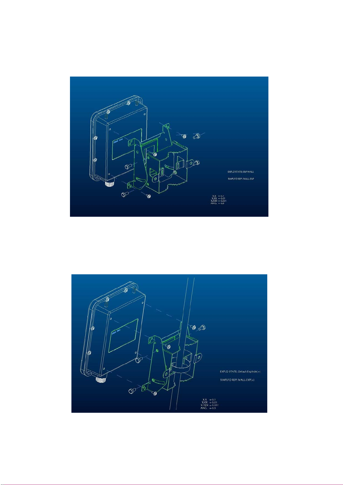
Page 8
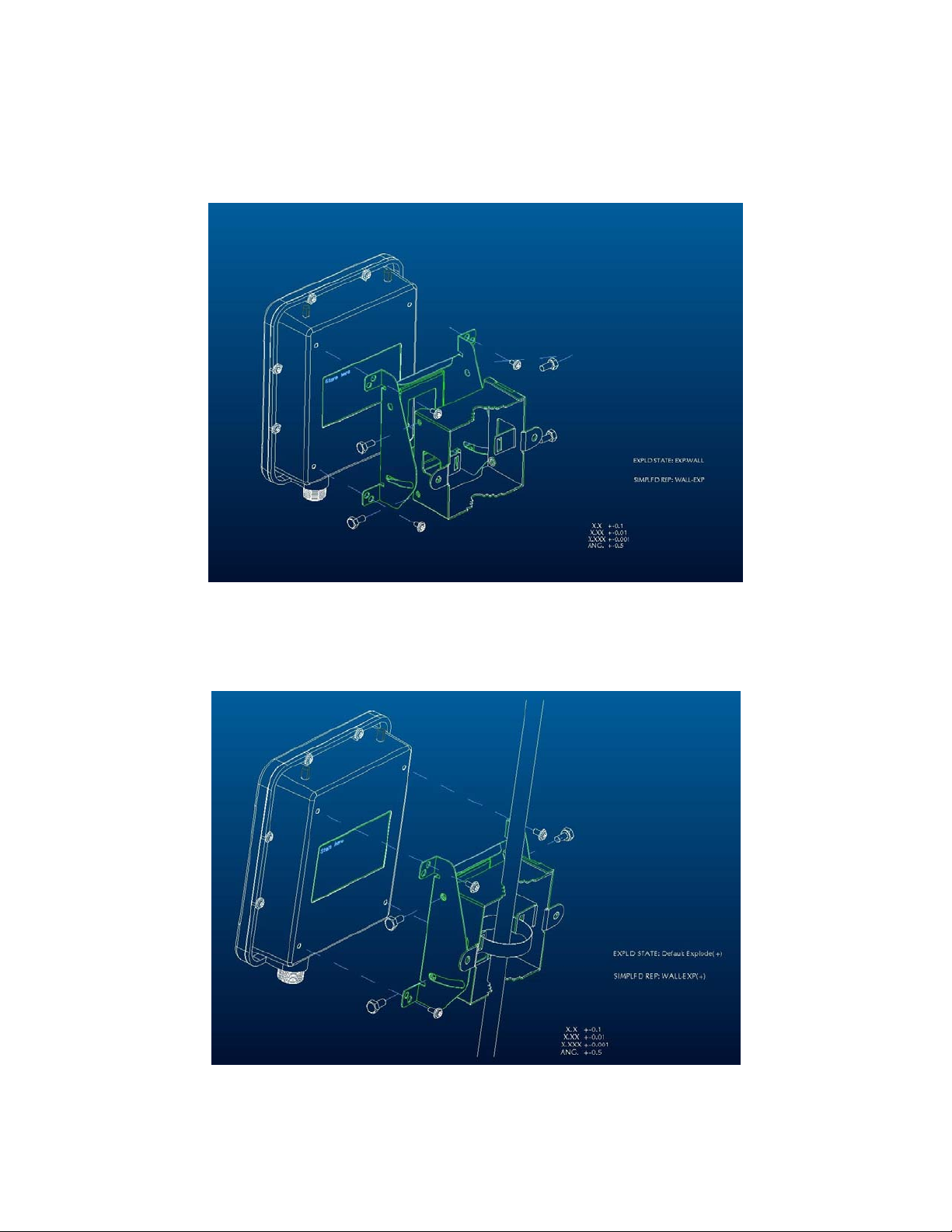
► Mount OW-2000 on A Wall/Mast
The OW-2000 can be mounted on the wall, you can use the Wall Mount
kit to mount the OW-2000 as shown in Figure 2-2.
Figure 2-2
You can also mount the OW-2000 to the mast as shown in Figure 2-3.
Figure 2-3
8
Page 9
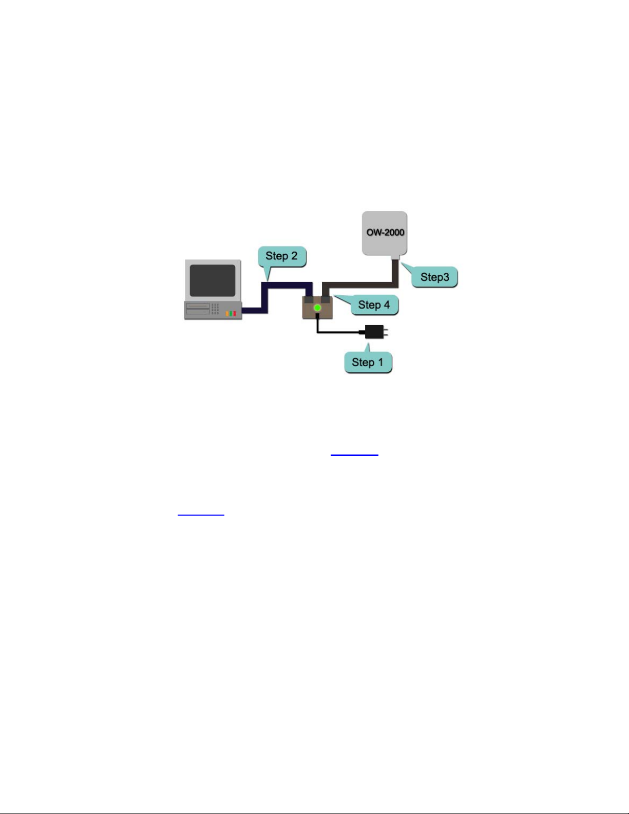
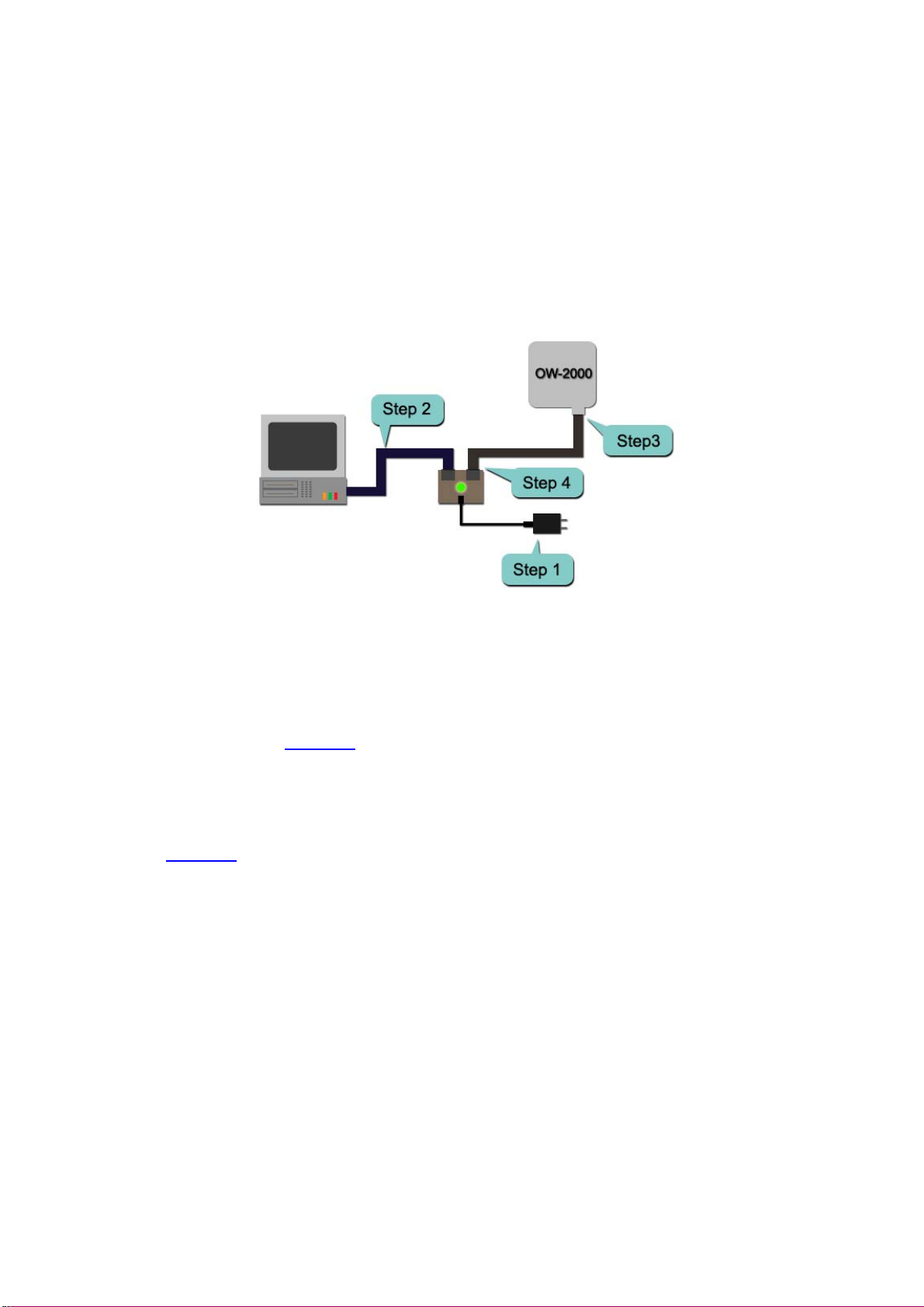
2.3 Preparing Installation
Before installing OW-2000 for outdoor application or hard-to-reach
location, we recommend configuring and test all the devices first.
For configuring the OW-2000, please follow the quick steps below to
power up the OW-2000. Refer to Figure 2-4 for steps 1 through 5.
Figure 2-4
Step1 : Connect the DC plug of the AC/DC power adapter into the DC
Input Port of Inline Power Injector and the wall-mount plug into a
power outlet or power strip (refer to page 6). The Power LED on the
Inline Power Injector will light up.
Step2 : Run the cross-over type uplink Ethernet cable from Data Input
Port (refer topage 6
) to the Ethernet port on a PC.
Step3 : Connect the 30m CAT 5 Ethernet cable into the OW-2000 unit.
Hand tighten the connector.
Step4 : Connect the remaining end of the 30m CA T 5 cable into the PoE
labeled AP/Bridge. This is the power side of the PoE that will power up
the OW-2000.
When the OW-2000 receives power over the Ethernet cable, the
OW-2000 will start its boot up sequence and the Active LED on the Inline
Power Injector will light up.
You can configure the OW-2000 via HTML browser, such as Microsoft
Internet Explorer or Netscape Navigator from a remote host or PC.
9
Page 10

2.4 Basic Configuration
2.4.1 Basic Configuration Steps
This section describes a two-step BASIC configuration procedure to
setup OW-2000.
Step1 : Modify the factory-default parameters on the web page
“/BASIC/LAN/”, and click Save Settings to save the changes, than
click Continue .
Step2 : Modify the factory-default para meters on the web page
“/BASIC/Wireless/”, and click Save Settings to save the changes,
than click Reboot the Device to take effect on the previous
configuration changes.
2.4.2 Logging into the Web Interface
The OW-2000 supports access to the configuration system through the
use of an HTTP Interface.
► Web Configuration
Before configuring OW-2000, the user needs to know the IP Address
assigned to the unit. When shipped from the factory, the IP Address
192.168.1.1 was assigned to the OW-2000 by default. To start a web
connection, use http://192.168.1.1
► Web Access Procedures
Once you identify the IP Address assigned to OW-2000, use web browser
to configure OW-2000 through the HTTP Interface. The following
procedure explains how to configure each item.
Step1 : Open your browser and enter the IP Address
Step2 : Press <ENTER> key and the OW-2000 Login screen appears as
shown in Figure 2-5.
10
Page 11
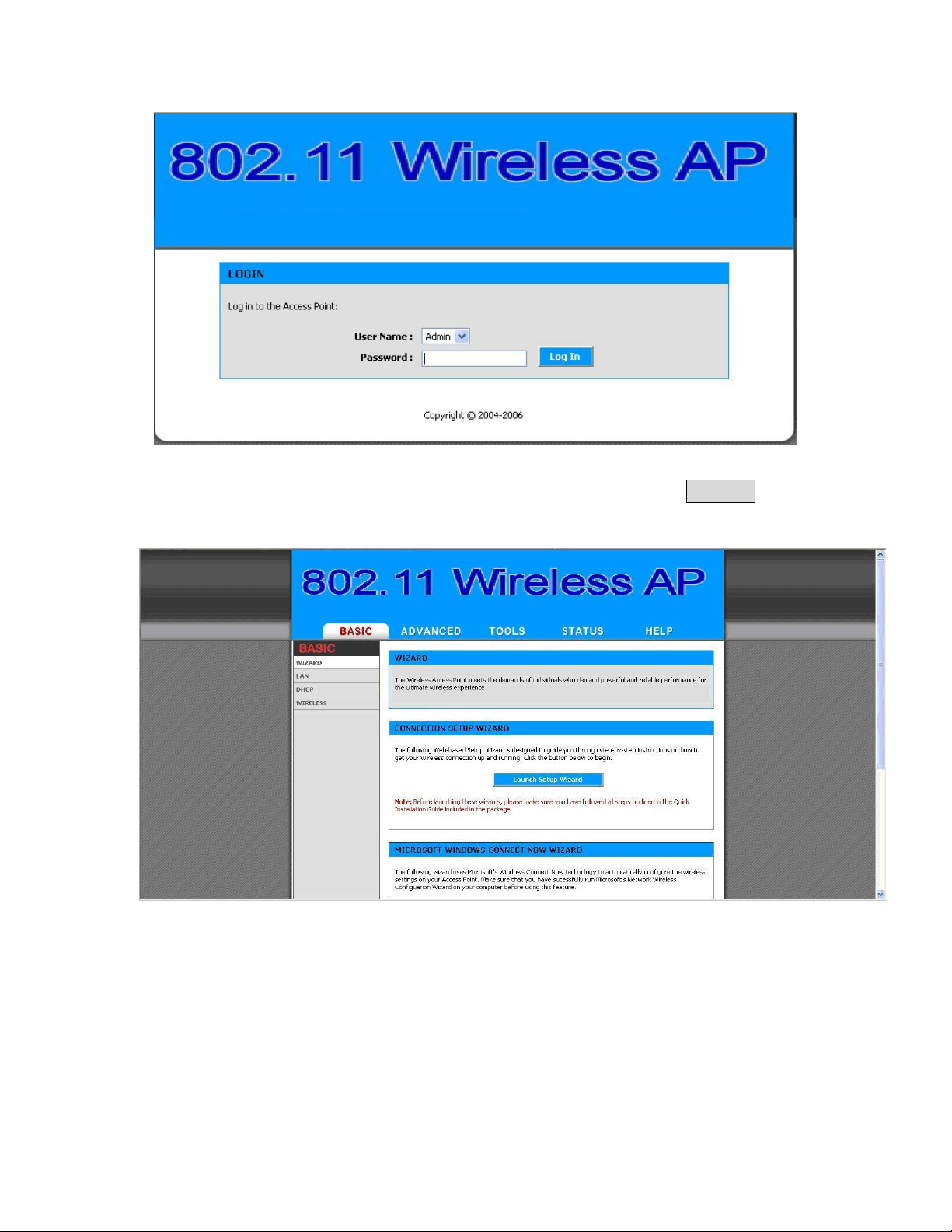
Figure 2-5
Step3 : Enter “admin” in the Password fields, and click Log In to
enter the web configuration user interface screen as shown below.
Figure 2-6
► Web Configuration Structure
The web configuration user interface shown above in Figure 2-6 is
grouped into a tree structure, and contains the following settings or
information.
11
Page 12

▽ BASIC
● WIZARD
● LAN
● DHCP
● WIRELESS
▽ ADVANCED
● MAC ADDRESS FILTER
● ADVANCED WIRELESS
▽ TOOLS
● ADMIN
● TIME
● SYSTEM
● FIRMWARE
▽ STATUS
● DEVICE INFO
● WIRELESS
● LOGS
● STATISTICS
▽ HELP
● MENU
● BASIC
● ADVANCED
● TOOLS
● STATUS
● GLOSSARY
Move through the tree by clicking on an icon to expand or collapse the
tree. The nodes on the tree represent web pages that allow viewing and
modifying the parameters.
12
Page 13
2.4.3 Set Operating Mode, IP Address, Subnet Mask, Default
Route IP, DNS Server IP of OW-2000
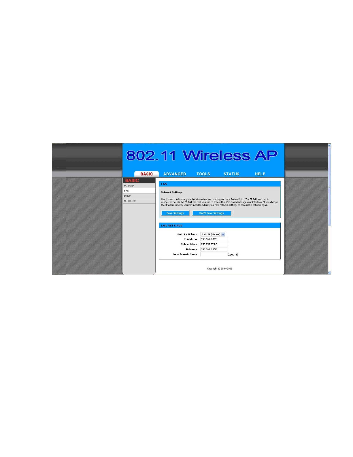
► LAN Settings
These are the settings of the LAN (Local Area Network) interface for the
Access Point. The Access Point's local network (LAN) settings are
configured based on the IP Address and Subnet Mask assigned in this
section. The IP address is also used to access this Web-based
management interface. This option is available in the “/BASIC/LAN/”
page as shown in Figure 2-7.
Figure 2-7
► Get LAN IP From
Choose "DHCP (Dynamic)" if your router supports DHCP and you want
the router to assign an IP address to the AP. In this case, you do not need
to fill in the following fields. Choose "Static IP (Manual)" if your router
does not support DHCP or if for any other reason you need to assign a
fixed address to the AP. In this case, you must also configure the
following fields.
Note that you cannot choose "DHCP (Dynamic)" if you have enabled the
"DHCP Server" option on the DHCP page; the AP cannot be both a DHCP
client and a DHCP server.
► IP Address
13
Page 14

The IP address of the AP on the local area network. Assign any unused IP
address in the range of IP addresses available for the LAN. For example,
192.168.0.1.
► Subnet Mask
The subnet mask of the local area network.
► Gateway
The IP address of the router on the local area network.
► Local Domain Name
This entry is optional. Enter a domain name for the local network. The
AP's DHCP server will give this domain name to the computers on the
wireless LAN. So, for example, if you enter mynetwork.net here, and you
have a wireless laptop with a name of chris, that laptop will be known as
chris.mynetwork.net. Note, however, if the AP's settings specify "DHCP
(Dynamic)" Address, and the router's DHCP server assigns a domain
name to the AP, that domain name will override any name you enter
here.
14
Page 15
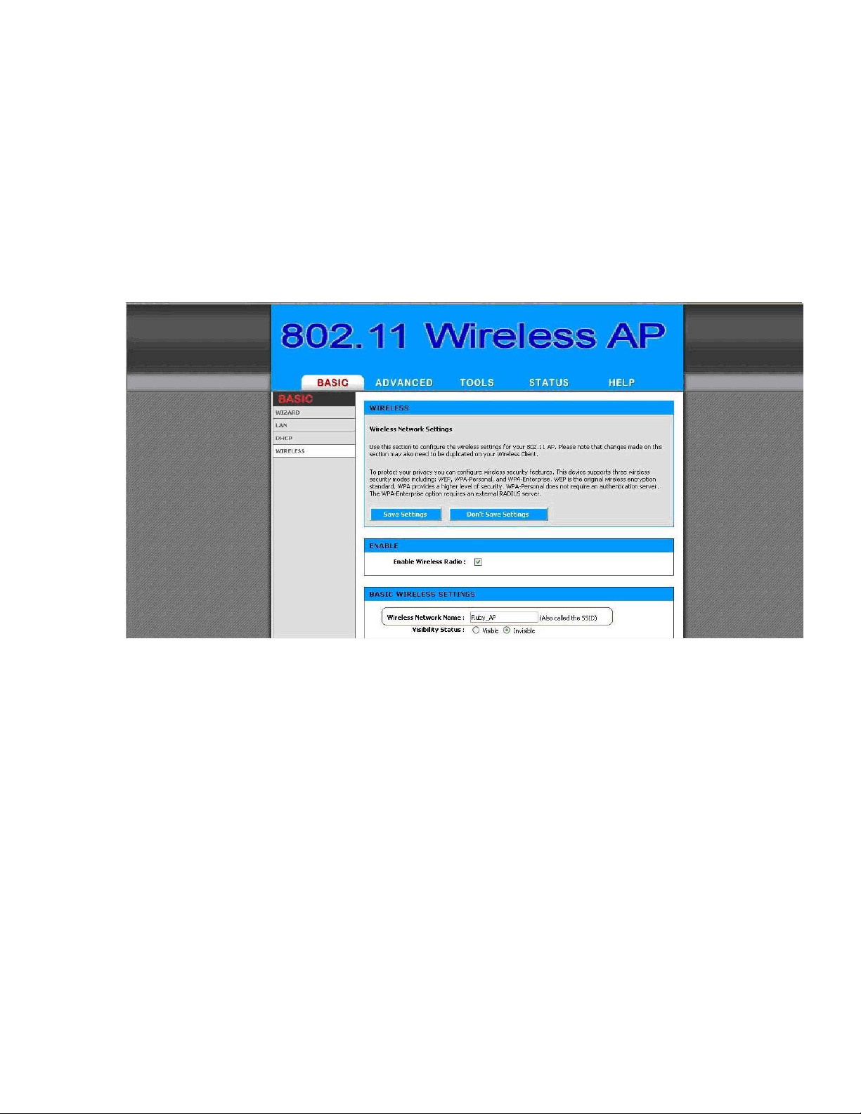
2.4.4 Set Wireless SSID for Wireless Interface
► Wireless Network Name (Also called the SSID)
When you are browsing for available wireless networks, this is the name
that will appear in the list (unless Visibility Status is set to Invisible, see
below). This name is also referred to as the SSID. For security purposes,
it is highly recommended to change from the pre-configured network
name. This option is available in the “/BASIC/WIRELESS/” page as
shown in Figure 2-8
Figure 2-8
15
Page 16

2.4.5 Set Wireless Encryption for Wireless Interface
The OW-2000 supports 64-bit and 128-bit WEP encryption.
For 64-bit WEP encryption, an encryption key is 10 hexadecimal
characters (0-9 and A-F) or 5 ASCII characters.
For 128-bit WEP encryption, an encryption key is 26 hexadecimal
characters or 13 ASCII characters.
Modify the WEP encryption parameters on the web page
“/BASIC/WIRELESS/WIRELESS SECURITY MODE”. Choice “WEP”
Enter 1~15 characters into the WEP Key field, than click Save
Setting ,Reboot the Device.
16
Page 17
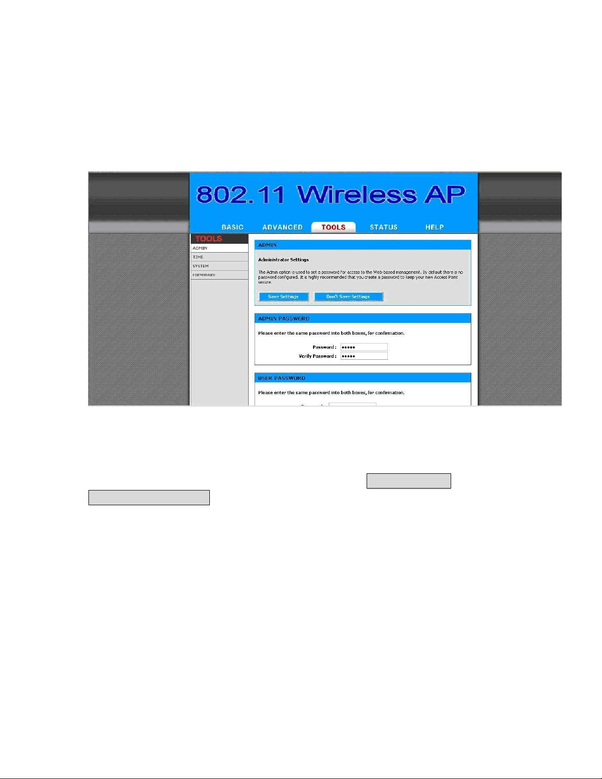
2.4.6 Change Supervisor Account & Password
Enter the TOOLS > ADMIN page. Figure 2-9 below shows the TOOLS/
ADMIN page.
Figure 2-9
ADMIN PASSWORD
►
Change the ADMIN PASSWORD’s user name and password in the
ADMIN PASSWORD Account field, and click Save Setting ,than
Reboot the Device. to take effect on the previous configuration
changes.
17
Page 18
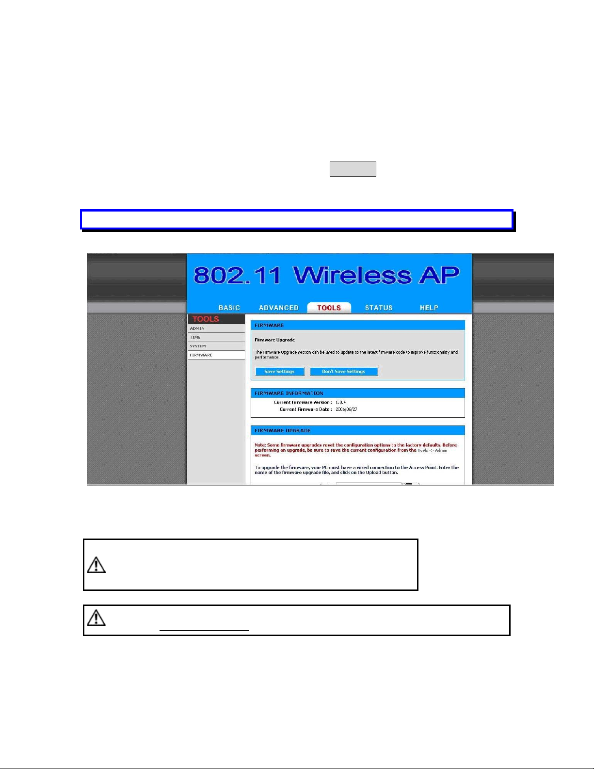
2.4.7 Upgrade the Firmware
► Update the Firmware
Enter the TOOLS > FIRMWARE page as shown in Figure 2-10 to
upgrade OW-2000. Here, user must select which file you want to
upgrade it (Program image), then click Upload button to start the
upgrade process.
Hint: It takes about 1 min, to complete the restart process.
Figure 2-10
Caution The Part 15 radio device operates on a non-interference basis with
other devices operating at this frequency when using integrated antennas. Any
changes or modification to the product not expressly approved by Original
Manufacture could void the user's authority to operate this device.
Caution To meet regulatory restrictions and the safety of the installation, strongly reco mmends this
product to be professionally installed
.
18
Page 19
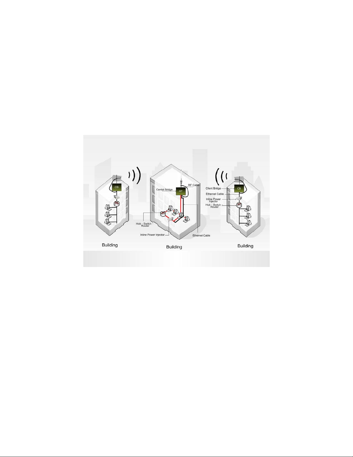
Chapter 3. Network Topologies
This chapter describes several common types of installations
implemented by using the OW-2000’s line of Outdoor Wireless System.
This is by no means intended to be an exhaustive list of all possible
configurations, but rather shows examples of some of the more common
implementations. The OW-2000 CB can be configured to function as a
Wireless Client Router or Bridge to a central access point like the
OW-2000 AP see Figure 3-1 below.
Figure 3-1
The OW-2000 CB performs in either router or bridge mode. In a
Point-to-Multipoint topology, all communication between network systems is done
through a centralized agent. Among the OW-2000 Outdoor Wireless Bridge
products, the centralized agent is Central Bridge (OW-2000 AP) and the individual
network notes may be Bridge (OW-2000 CB ).
To show the available Point-to-Multipoint topologies, the following examples are
provided.
Wireless Client Bridge-to-Central Wireless Bridge
19
Page 20
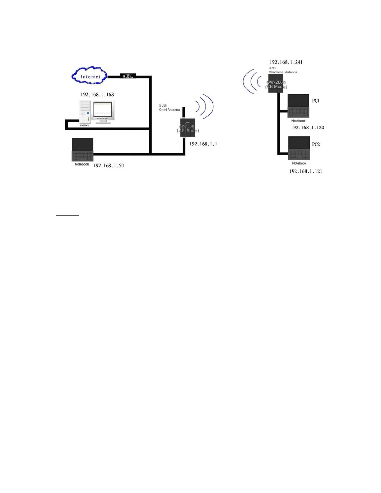
3.1 Wireless Client Bridge-to-Central Wireless Bridge
Figure 3-2
Refer to Figure 3-2 for the following setup.
Note: The OW-2000 AP is the Central Wireless Bridge and OW -2000 CB
is the Wireless Client Bridge
Step 1 Set the OW-2000 AP to perform a bridge (bridge IP address:
192.168.1.1).
Step 2 Set Wireless parameters on the AP11 to: Channel (1) and SSID
(wireless)
Step 3 Set the OW-2000 CB to function in the bridge mode (bridge IP
address: 192.168.1.241).
Step 4 Set Wireless parameters on the OW-2000 CB to: Channel (1)
and SSID (wireless), and these parameters must be the same with
COU.
Step 5 Left side subnet is transparent to the right side.
Step 6 DHCP server assign IP address to PC1 and PC2
20
Page 21

Chapter 4. All function on Device
4.1 BASIC
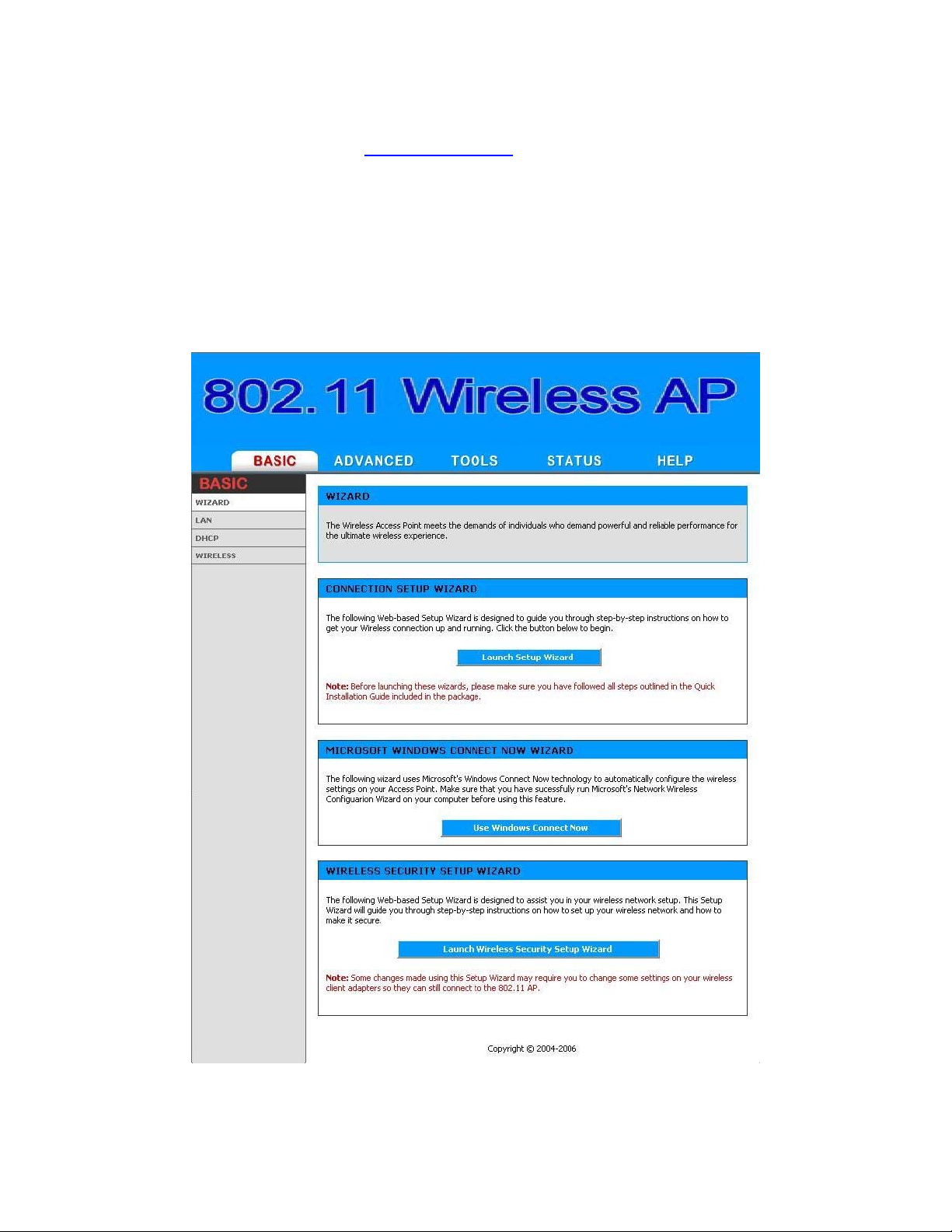
4.1.1 Wizard
This wizard guides you through the following basic Access Point
setup steps:
Set your Password
Select your Time Zone
Configure your Wireless Connection
WCN Wizard
If your PC's operating system is Windows XP Service Pack 2 (SP2)
or later and you are using Windows Internet Explorer (IE) as your
browser, you can use Windows Connect Now (WCN) technology to
help configure the Access Point's wireless security settings.
Wireless Network Setup Wizard
Before you can use the Access Point's WCN Wizard, you must first
execute the Wireless Network Setup Wizard on your PC. If you
have not already done so, go to the Windows Control Panel and
select Wireless Network Setup Wizard. When the Wireless Network
Setup Wizard gives you the choice to "Use a USB flash drive" or
"Set up a network manually", choose the latter. (In fact, you will
not have to do the set-up manually; it will be done with the WCN
ActiveX Control.)
WCN ActiveX Control
The WCN ActiveX Control provides the WCN link between your PC
and the Access Point via the browser that communicates wireless
configuration data without a USB flash drive. The browser will
attempt to download the WCN ActiveX Control, if it is not already
available on your PC. F or this action to succeed, you must already
have a WAN connection, and the browser's internet security
setting must be Medium or lower (select Tools -> Internet Options
-> Security -> Custom Level -> Medium).
When the necessary preparations are complete, the WCN
technology will propagate the wireless network settings from your
PC to the Access Point. Then you will have to reboot the Access
Point for the settings to take effect.
21
Page 22
Note that WCN only sets a few of the wireless options. Y ou will still
need to go to the Home -> Wireless page to set other wireless
options such as Super G Mode and transmission rate.
Wireless Security Setup Wizard
This wizard guides you through the following steps for setting up
security for your wireless network:
Name your Wireless Network
Secure your Wireless Network
Figure 4-1
22
Page 23
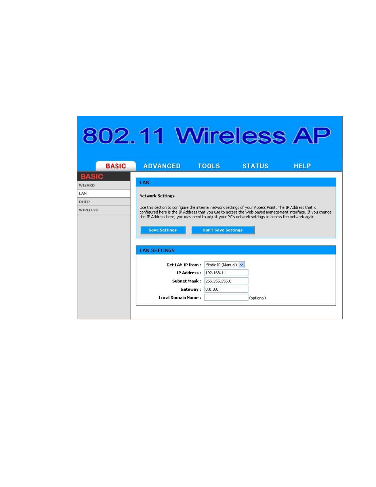
4.1.2 LAN
These are the settings of the LAN (Local Area Network) interface
for the Access Point. The Access Point's local network (LAN)
settings are configured based on the IP Address and Subnet Mask
assigned in this section. The IP address is also used to access this
Web-based management interface.
Figure 4-2
Get LAN IP From
Choose "DHCP (Dynamic)" if your router supports DHCP and you
want the router to assign an IP address to the AP. In this case, you
do not need to fill in the following fields. Choose "Static IP
(Manual)" if your router does not support DHCP or if for any other
reason you need to assign a fixed address to the AP. In this case,
you must also configure the following fields.
Note that you cannot choose "DHCP (Dynamic)" if you have
enabled the "DHCP Server" option on the DHCP page; the AP
cannot be both a DHCP client and a DHCP server.
23
Page 24

IP Address
The IP address of the AP on the local area network. Assign any
unused IP address in the range of IP addresses available for the
LAN. For example, 192.168.1.101.
Subnet Mask
The subnet mask of the local area network.
Gateway
The IP address of the router on the local area network.
Local Domain Name
This entry is optional. Enter a domain name for the local network.
The AP's DHCP server will give this domain name to the computers
on the wireless LAN. So, for example, if you enter
mynetwork.net here, and you have a wireless laptop with a
name of chris, that laptop will be known as
chris.mynetwork.net. Note, however, if the AP's settings specify
"DHCP (Dynamic)" Address, and the router's DHCP server assigns
a domain name to the AP, that domain name will override any
name you enter here.
24
Page 25
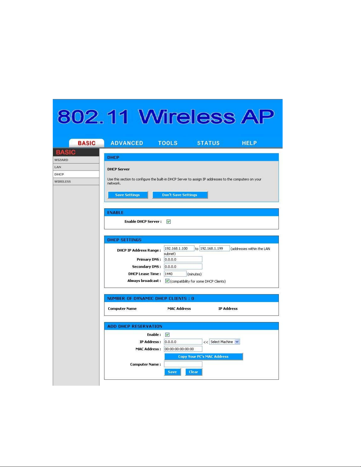
4.1.3 DHCP
DHCP stands for Dynamic Host Configuration Protocol. The DHCP section
is where you configure the built-in DHCP Server to assign IP addresses to
the computers and other devices on your local area network (LAN).
Enable DHCP Server
Figure 4-3
25
Page 26

In most situations, the router provides DHCP services, and you can
leave this option disabled. However, if for any reason the router
does not provide DHCP services, enable this option. The AP's DHCP
Server will then manage the IP addresses and other network
configuration information for wireless clients associated with the
AP.
The computers (and other devices) connected to your LAN also
need to have their TCP/IP configuration set to "DHCP" or "Obtain
an IP address automatically".
When you set Enable DHCP Server, the following options are
displayed.
DHCP IP Address Range
These two IP values (from and to) define a range of IP addresses
that the DHCP Server uses when assigning addresses to
computers and devices on your Local Area Network. Any addresses
that are outside of this range are not managed by the DHCP Server;
these could, therefore, be used for manually configured devices or
devices that cannot use DHCP to obtain network address details
automatically.
It is possible for a computer or device that is manually configured
to have an address that does reside within this range. In this case
the address should be reserved (see Static DHCP Client below), so
that the DHCP Server knows that this specific address can only be
used by a specific computer or device.
Your Access Point, by default, has a static IP address of
192.168.1.1. This means that addresses 192.168.1.2 to
192.168.1.254 can be made available for allocation by the DHCP
Server.
Example:
Your Access Point uses 192.168.1.1 for the IP address. You've
assigned a computer that you want to designate as a Web server
with a static IP address of 192.168.1.3. You've assigned another
computer that you want to designate as an FTP server with a static
IP address of 192.168.1.4. Therefore the starting IP address for
your DHCP IP address range needs to be 192.168.1.5 or greater.
Example:
Suppose you configure the DHCP Server to manage addresses
From 192.168.1.100 To 192.168.1.199. This means that
192.168.1.3 to 192.168.1.99 and 192.168.1.200 to
192.168.1.254 are NOT managed by the DHCP Server. Computers
or devices that use addresses from these ranges are to be
26
Page 27

manually configured. Suppose you have a web server computer
that has a manually configured address of 192.168.1.100.
Because this falls within the "managed range" be sure to create a
reservation for this address and match it to the relev ant computer
(see Static DHCP Client below).
DHCP Lease Time
The amount of time that a computer may have an IP address
before it is required to renew the lease. The lease functions just as
a lease on an apartment would. The initial lease designates the
amount of time before the lease expires. If the tenant wishes to
retain the address when the lease is expired then a new lease is
established. If the lease expires and the address is no longer
needed than another tenant may use the address.
Always Broadcast
If all the computers on the LAN successfully obtain their IP
addresses from the Access Point's DHCP server as expected, this
option can remain disabled. However, if one of the computers on
the LAN fails to obtain an IP address from the Access Point's DHCP
server, it may have an old DHCP client that incorrectly turns off the
broadcast flag of DHCP packets. Enabling this option will cause the
Access Point to always broadcast its responses to all clients,
thereby working around the problem, at the cost of increased
broadcast traffic on the LAN.
Number of Dynamic DHCP Clients
In this section you can see what LAN devices are currently leasing
IP addresses.
Revoke: The Revoke option is available for the situation in which
the lease table becomes full or nearly full, you need to recover
space in the table for new entries, and you know that some of the
currently allocated leases are no longer needed. Clicking Revoke
cancels the lease for a specific LAN device and frees an entry in the
lease table. Do this only if the device no longer needs the leased IP
address, because, for example, it has been removed from the
network.
Add/Edit DHCP Reservation
This option lets you reserve IP addresses, and assign the same IP
address to the network device with the specified MAC address any
time it requests an IP address. This is almost the same as when a
device has a static IP address except that the device must still
request an IP address from the Access Point. The Access Point will
provide the device the same IP address every time. DHCP
27
Page 28

Reservations are helpful for serv er computers on the local network
that are hosting applications such as Web and FTP. Servers on your
network should either use a static IP address or use this option.
MAC Address: To input the MAC address of your system, enter it
in manually or connect to the Access Point's Web-Management
interface from the system and click the Copy Your PC's MAC
Address button.
A MAC address is usually located on a sticker on the bottom of a
network device. The MAC address is comprised of twelve digits.
Each pair of hexadecimal digits are usually separated by dashes or
colons such as 00-0D-88-11-22-33 or 00:0D:88:11:22:33. If your
network device is a computer and the network card is already
located inside the computer, you can connect to the Access Point
from the computer and click the Copy Your PC's MAC Address
button to enter the MAC address.
As an alternative, you can locate a MAC address in a specific
operating system by following the steps below:
Windows 98
Windows Me
Go to the Start menu, select Run, type in winipcfg, and
hit Enter. A popup window will be displayed. Select the
appropriate adapter from the pull-down menu and you
will see the Adapter Address. This is the MAC address of
the device.
Windows
2000
Windows XP
Go to your Start menu, select Programs, select
Accessories, and select Command Prompt. At the
command prompt type ipconfig /all and hit Enter. The
physical address displayed for the adapter connecting to
the Access Point is the MAC address.
Mac OS X Go to the Apple Menu, select System Preferences, select
Network, and select the Ethernet Adapter connecting to
the Access Point. Select the Ethernet button and the
Ethernet ID will be listed. This is the same as the MAC
address.
Computer Name: Y ou can assign a name for each computer that
is given a reserved IP address. This may help you keep track of
which computers are assigned this way.
Example:
Game Server
DHCP Reservations List
This shows clients that you have specified to have reserv ed DHCP
addresses. An entry can be changed by clicking the Edit icon, or
28
Page 29

deleted by clicking the Delete icon. When you click the Edit icon,
the item is highlighted, and the "Edit DHCP Reserv ation" section is
activated for editing.
29
Page 30
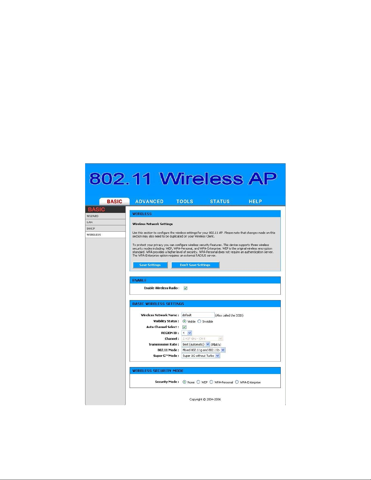
4.1.4 WIRELESS
The wireless section is used to configure the wireless settings for your
Access Point. Please note that changes made on this section may also
need to be duplicated on your Wireless Client.
To protect your privacy, use the wireless security mode to configure the
wireless security features. This device supports three wireless security
modes including: WEP, WPA-Personal, and WPA-Enterprise. WEP is the
original wireless encryption standard. WPA provides a higher level of
security. WPA-Personal does not require an authentication server. The
WPA-Enterprise option does require a RADIUS authentication server.
Enable Wireless Radio
Figure 4-4
30
Page 31

This option turns off and on the wireless connection feature of the
Access Point. When you set this option, the following parameters
are displayed.
Wireless Network Name
When you are browsing for available wireless networks, this is the
name that will appear in the list (unless Visibility Status is set to
Invisible, see below). This name is also referred to as the SSID. For
security purposes, it is highly recommended to change from the
pre-configured network name.
Visibility Status
The Invisible option allows you to hide your wireless network.
When this option is set to Visible, your wireless network name is
broadcast to anyone within the range of your signal. If you're not
using encryption then they could connect to your network. When
Invisible mode is enabled, you must enter the Wireless Network
Name (SSID) on the client manually to connect to the network.
REGION ID
By default the value 4 will be selected. The default value 4
represents FCC1_FCCA (USA). You have the option of selecting the
region id if necessary. 1: For 11b-only countries, 2: Israel, 4: USA,
5: Hong Kong, 6: Canada, 7: Australia, 10: France, 11: Bulgaria,
12: Hungary & others, 13: France & others, 116; Japan, 17: Japan,
18: Singapore, 19:Japan with 4.9G channels, 20: Korea, 22:
Korea with 2.3G channels, 23: Latin America, 25: Venezuela, 26
World0 (WO0 SKU), 27: World1 (WO1 SKU), 28: World2 (WO2
SKU), 29: World3 (WO3 SKU), 30: World4 (WO4 SKU), 31: World5
(W05 SKU).
Auto Channel Select
If you select this option, the Access Point automatically finds the
channel with least interference and uses that channel for wireless
networking. If you disable this option, the Access Point uses the
channel that you specify with the following Channel option.
Channel
A wireless network uses specific channels in the 2.4GHz wireless
spectrum to handle communication between clients. Some
channels in your area may have interference from other electronic
devices. Choose the clearest channel to help optimize the
performance and coverage of your wireless network.
Transmission Rate
31
Page 32

By default the fastest possible transmission rate will be selected.
You have the option of selecting the speed if necessary.
802.11 Mode
If all of the wireless devices you want to connect with this Access
Point can connect in 802.11g mode, you can improve performance
slightly by changing the mode to 802.11g only. If you have some
devices that are 802.11b, leave the setting at Mixed.
Super G™ Mode
Super G without Turbo: Performance enhancing features such
as Packet Bursting, FastFrames, and Compression.
WEP
A method of encrypting data for wireless communication intended
to provide the same level of privacy as a wired network. WEP is not
as secure as WPA encryption. To gain access to a WEP network,
you must know the key. The key is a string of characters that you
create. When using WEP, you must determine the level of
encryption. The type of encryption determines the key length.
128-bit encryption requires a longer key than 64-bit encryption.
Keys are defined by entering in a string in HEX (hexadecimal using characters 0-9, A-F) or ASCII (American Standard Code for
Information Interchange - alphanumeric characters) format.
ASCII format is provided so you can enter a string that is easier to
remember. The ASCII string is converted to HEX for use over the
network. Four keys can be defined so that you can change keys
easily. A default key is selected for use on the network.
Example:
64-bit hexadecimal keys are exactly 10 characters in length.
(12345678FA is a valid string of 10 characters for 64-bit
encryption.)
128-bit hexadecimal keys are exactly 26 characters in length.
(456FBCDF123400122225271730 is a valid string of 26 characters
for 128-bit encryption.)
64-bit ASCII keys are up to 5 characters in length (DMODE is a
valid string of 5 characters for 64-bit encryption.)
128-bit ASCII keys are up to 13 characters in length
(2002HALOSWIN1 is a valid string of 13 characters for 128-bit
encryption.)
WPA-Personal and WPA-Enterprise
32
Page 33

Both of these options select some variant of Wi-Fi Protected Access
(WPA) -- security standards published by the Wi-Fi Alliance. The
WPA Mode further refines the variant that the Access Point should
employ.
WPA Mode: WPA is the older standard; select this option if the
clients that will be used with the Access Point only support the
older standard. WPA2 is the newer implementation of the stronger
IEEE 802.11i security standard. With the "WPA2" option, the
Access Point tries WPA2 first, but falls back to WPA if the client only
supports WPA. With the "WPA2 Only" option, the Access Point
associates only with clients that also support WPA2 security.
Cipher Type: The encryption algorithm used to secure the data
communication. TKIP (Temporal Key Integrity Protocol) provides
per-packet key generation and is based on WEP. AES (Advanced
Encryption Standard) is a very secure block based encryption.
With the "TKIP and AES" option, the Access Point negotiates the
cipher type with the client, and uses AES when available.
Group Key Update Interval: The amount of time before the
group key used for broadcast and multicast data is changed.
WPA-Personal
This option uses Wi-Fi Protected Access with a Pre-Shared Key
(PSK).
Pre-Shared Key: The key is entered as a pass-phrase of up to 63
alphanumeric characters in ASCII (American Standard Code for
Information Interchange) format at both ends of the wireless
connection. It cannot be shorter than eight characters, although
for proper security it needs to be of ample length and should not be
a commonly known phrase. This phrase is used to generate
session keys that are unique for each wireless client.
Example:
Wireless Networking technology enables ubiquitous
communication
WPA-Enterprise
This option works with a RADIUS Server to authenticate wireless
clients. Wireless clients should have established the necessary
credentials before attempting to authenticate to the Server
through this Gateway. Furthermore, it may be necessary to
configure the RADIUS Server to allow this Gateway to authenticate
users.
33
Page 34

Authentication Timeout: Amount of time before a client will be
required to re-authenticate.
RADIUS Server IP Address: The IP address of the
authentication server.
RADIUS Server Port: The port number used to connect to the
authentication server.
RADIUS Server Shared Secret: A pass-phrase that must match
with the authentication server.
MAC Address Authentication: If this is selected, the user must
connect from the same computer whenever logging into the
wireless network.
Advanced:
Optional Backup RADIUS Server
This option enables configuration of an optional second RADIUS
server. A second RADIUS server can be used as backup for the
primary RADIUS server. The second RADIUS server is consulted
only when the primary server is not available or not responding.
The fields Second RADIUS Server IP Address, RADIUS Server
Port, Second RADIUS server Shared Secret, Second MAC
Address Authentication provide the corresponding parameters
for the second RADIUS Server.
34
Page 35

4.2 ADVANCED
4.2.1 MAC Address Filter
The MAC address filter section can be used to filter network access by
machines based on the unique MAC addresses of their network
adapter(s). It is most useful to prevent unauthorized wireless devices
from connecting to your network. A MAC address is a unique ID assigned
by the manufacturer of the network adapter.
Enable MAC Address Filter
When this is enabled, computers are granted or denied network
access depending on the mode of the filter.
Note: Misconfiguration of this feature can prevent any machine
from accessing the network. In such a situation, you can regain
access by activating the factory defaults button on the Access
Point itself.
Figure 4-5
35
Page 36

Filter Settings
Mode
When "only allow listed machines" is selected, only computers with
MAC addresses listed in the MAC Address List are granted network
access. When "only deny listed machines" is selected, any
computer with a MAC address listed in the MAC Address List is
refused access to the network.
Filter Wireless Clients
When this is selected, the MAC address filters will be applied to
wireless network clients.
Filter Wired Clients
When this is selected, the MAC address filters will be applied to
wired network clients.
Add/Edit MAC Address
In this section, you can add entries to the MAC Address List below,
or edit existing entries.
Enable
MAC address entries can be activated or deactivated with this
checkbox.
MAC Address
Enter the MAC address of the desired computer or connect to the
Access Point from the desired computer and click the Copy Your
PC's MAC Address button.
Save
Saves the new or edited MAC Address entry in the following list.
When finished updating the MAC Address List, you must still click
the Save Settings button at the top of the page to make the
changes effective and permanent.
MAC Address List
The section lists the current MAC Address filters. A MAC Address
entry can be changed by clicking the Edit icon, or deleted by
clicking the Delete icon. When you click the Edit icon, the item is
highlighted, and the "Edit MAC Address" section is activated for
editing.
36
Page 37
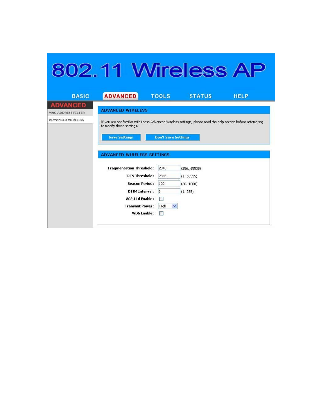
4.2.2 Advance Wireless
Fragmentation Threshold
This setting should remain at its default value of 2346. Setting the
Fragmentation value too low may result in poor performance.
RTS Threshold
This setting should remain at its default value of 2346. If you
encounter inconsistent data flow, only minor modifications to the
value are recommended.
Beacon Period
Beacons are packets sent by a wireless Access Point to synchronize
wireless devices. Specify a Beacon Period value between 20 and
1000. The default value is set to 100 milliseconds.
DTIM Interval
A DTIM is a countdown informing clients of the next window for
listening to broadcast and multicast messages. When the wireless
Figure 4-6
37
Page 38

Access Point has buffered broadcast or multicast messages for
associated clients, it sends the next DTIM with a DTIM Interval
value. Wireless clients detect the beacons and awaken to receive
the broadcast and multicast messages. The default value is 1.
Valid settings are between 1 and 255.
802.11d Enable
Enables 802.11d operation. 802.11d is a wireless specification for
operation in additional regulatory domains. This supplement to the
802.11 specifications defines the physical layer requirements
(channelization, hopping patterns, new values for current MIB
attributes, and other requirements to extend the operation of
802.11 WLANs to new regulatory domains (countries). The current
802.11 standard defines operation in only a few regulatory
domains (countries). This supplement adds the requirements and
definitions necessary to allow 802.11 WLAN equipment to operate
in markets not served by the current standard. Enable this option
if you are operating in one of these "additional regulatory
domains".
Transmit Power
Normally the wireless transmitter operates at 100% power. In
some circumstances, however, there might be a need to isolate
specific frequencies to a smaller area. By reducing the power of the
radio, you can prevent transmissions from reaching beyond your
corporate/home office or designated wireless area.
WDS Enable
When WDS is enabled, this access point functions as a wireless
repeater and is able to wirelessly communicate with other APs via
WDS links. Note that WDS is incompatible with WPA -- both
features cannot be used at the same time. A WDS link is
bidirectional; so this AP must know the MAC Address (creates the
WDS link) of the other AP, and the other AP must have a WDS link
back to this AP. Make sure the APs are configured with same
channel number.
WDS AP MAC Address
Specifies one-half of the WDS link. The other AP must also have
the MAC address of this AP to create the WDS link back to this AP.
38
Page 39

4.3 TOOLS
4.3.1 Admin
The Admin option is used to set a password for access to the Web-based
management. By default there is no password configured. It is highly
recommended that you create a password to keep your new Access Point
secure.
39
Page 40

Admin Password
Enter a password for the user "admin", who will have full access to
the Web-based management interface.
User Password
Enter a password for the user "user", who will have read-only
access to the Web-based management interface.
Access Point Name
The name of the Access Point can be changed here.
Admin Idle Timeout
The amount of time before the administration session (either
remote or local) is closed when there is no activity.
Save Configuration
Figure 4-7
This option allows you to save the Access Point's configuration to a
file on your computer. Be sure to save the configuration before
performing a firmware upgrade.
Restore Configuration from File
Use this option to load previously saved Access Point configuration
settings.
Save Configuration To Wireless Network Setup Wizard
If your PC's operating system is Windows XP Service Pack 2 (SP2)
or later and you are using Windows Internet Explorer (IE) as your
browser, you can use this option to save key parts of the Access
Point's current wireless security settings to your PC with Windows
Connect Now (WCN) technology. The settings will then be
available to propagate to other wireless devices.
WCN ActiveX Control
The WCN ActiveX Control provides the necessary WCN link
between the Access Point and your PC via the browser. The
browser will attempt to download the WCN ActiveX Control, if it is
not already available on your PC. For this action to succeed, the
WAN connection must be established, and the browser's internet
security setting must be Medium or lower (select Tools -> Internet
Options -> Security -> Custom Level -> Medium).
Click the Save to Windows Connect Now button, and the WCN
technology will capture the wireless network settings from your
Access Point and save them on your PC.
40
Page 41

Note that WCN only saves a few of the wireless security settings.
When you use WCN to propagate settings to other wireless devices,
you may have to make additional settings manually on those
devices.
Note that, in Microsoft's current implementation of WCN, you
cannot save the wireless settings if a profile of the same name
already exists. To work around this limitation, either delete the
existing profile or change the SSID when you change the wireless
settings; then, when you save the new settings, a new profile will
be created.
41
Page 42
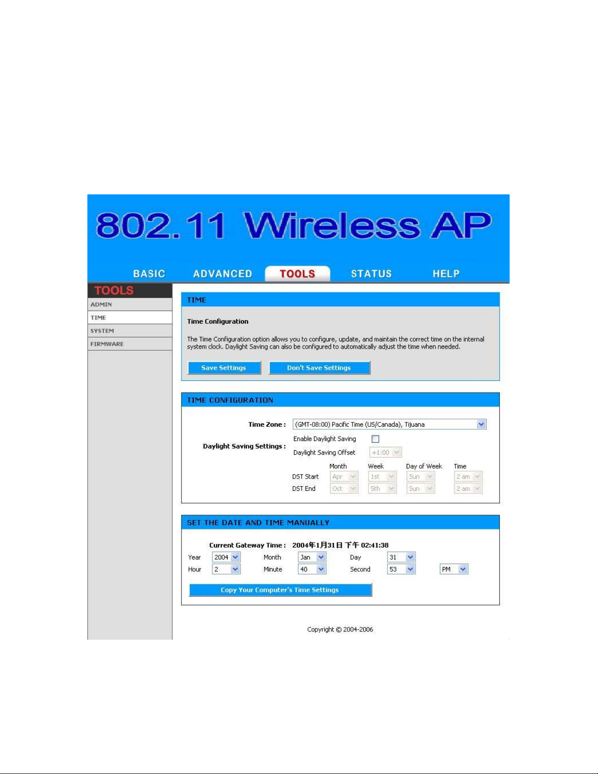
4.3.2 Time
The Time Configuration option allows you to configure, update, and
maintain the correct time on the Access Point's internal system clock.
From this section you can set the time zone that you are in and set the
Time Server. Daylight saving can also be configured to automatically
adjust the time when needed.
Figure 4-8
42
Page 43

Time Configuration
Time Zone
Select your local time zone from pull down menu.
Daylight Saving Enable
Check this option if your location observes daylight saving time.
Daylight Saving Offset
Select the time offset, if your location observes daylight saving
time.
DST Start and DST End
Select the starting and ending times for the change to and from
daylight saving time. For example, suppose for DST Start you
select Month="Oct", Week="3rd", Day="Sun" and Time="2am".
This is the same as saying: "Daylight saving starts on the third
Sunday of October at 2:00 AM."
Set the Date and Time Manually
If you do not have the NTP Server option in effect, you can either
manually set the time for your Access Point here, or you can click
the Copy Your Computer's Time Settings button to copy the
time from the computer you are using. (Make sure that computer's
time is set correctly.)
Note: If the Access Point loses power for any reason, it cannot keep its
clock running, and will not have the correct time when it is started again.
To maintain correct time for schedules and logs, either you must enter
the correct time after you restart the Access Point, or you must enable
the NTP Server option.
43
Page 44

4.3.3 System
This section allows you to reboot the device, and restore the Access Point
to the factory default settings. Restoring the unit to the factory default
settings will erase all settings, including any rules that you've created.
Figure 4-9
Reboot the Device
This restarts the Access Point. Useful for restarting when you are
not near the device.
Restore all Settings to the Factory Defaults
This option restores all configuration settings back to the settings
that were in effect at the time the Access Point was shipped from
the factory. Any settings that have not been saved will be lost. If
you want to save y our Access Point configuration settings, y ou can
do so from the Tools -> Admin page.
44
Page 45
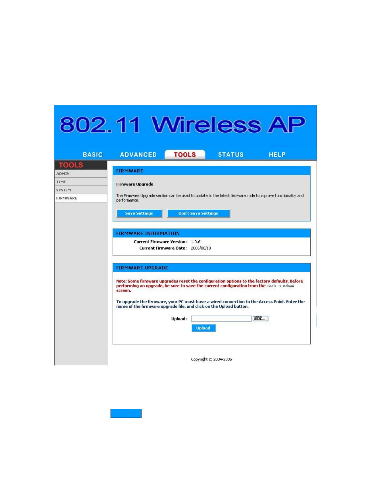
4.3.4 Firmware
The Firmware Upgrade section can be used to update to the latest
firmware code to improve functionality and performance.
Figure 4-10
To upgrade the firmware, follow these steps:
1. Click the Browse button to locate the upgrade file on your
computer.
45
Page 46

2. Once you have found the file to be used, click the Upload button
below to start the firmware upgrade process. This can take a
minute or more.
3. Wait for the Access Point to reboot. This can take another minute
or more.
4. Confirm updated firmware revision on status page.
Firmware Information
Here are displayed the version numbers of the firmw are currently
installed in your Access Point and the most recent upgr ade that is
available.
Firmware Upgrade
Note: Firmware upgrade cannot be performed from a wireless
device. T o perform an upgrade, ensure that y ou are using a PC that
is connected to the Access Point by wire.
Note: Some firmware upgrades reset the configur ation options to
the factory defaults. Before performing an upgrade, be sure to
save the current configuration from the Tools -> Admin screen.
Upload
Once you have a firmware update on yo ur computer, use this
option to browse for the file and then upload the information into
the Access Point.
46
Page 47
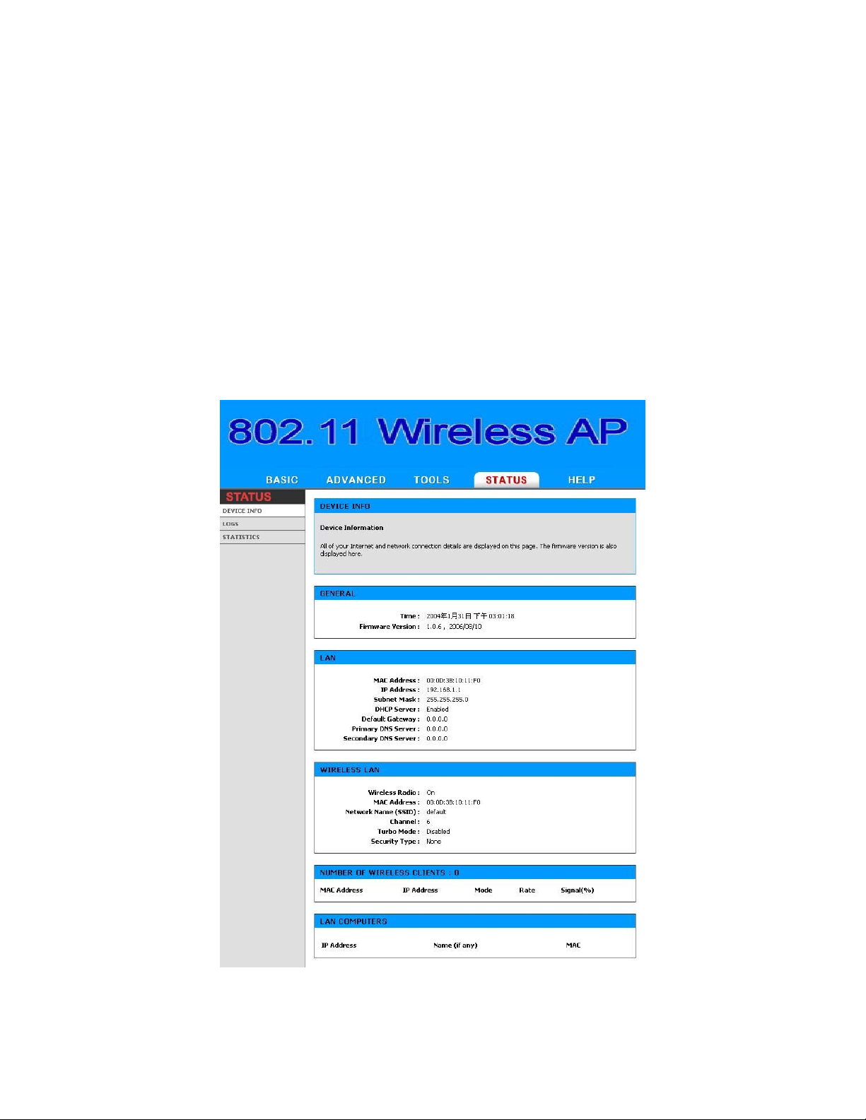
4.4 Status
4.4.1 Device Info
All of your Internet and network connection details are displayed on the
Device Info page. The firmware version is also displayed here.
Note: Some browsers have limitations that make it impossible to
update the WAN status display when the status changes. Some
browsers require that you refresh the display to obtain updated
status. Some browsers report an error condition when trying to
obtain WAN status.
Figure 4-11
47
Page 48

LAN Computers
This area of the screen continually updates to show all DHCP
enabled computers and devices connected to the LAN side of your
Access Point. The detection "range" is limited to the address r ange
as configured in DHCP Server. Computers that have an address
outside of this range will not show . If the DHCP Client (i.e. a
computer configured to "Automatically obtain an address")
supplies a Host Name then that will also be shown. Any computer
or device that has a static IP address that lies within the detection
"range" may show, however its host name will not.
WIRELESS
The wireless section allows you to view the wireless clients that are
connected to your wireless Access Point.
MAC Address
The Ethernet ID (MAC address) of the wireless client.
IP Address
The LAN-side IP address of the client.
Mode
The transmission standard being used by the client. Values are 11a,
11b, or 11g for 802.11a, 802.11b, or 802.11g respectively.
Rate
The actual transmission rate of the client in megabits per second.
Signal
This is a relative measure of signal quality. The value is expressed
as a percentage of theoretical best quality. Signal quality can be
reduced by distance, by interference from other radio-frequency
sources (such as cordless telephones or neighboring wireless
networks), and by obstacles between the Access Point and the
wireless device.
48
Page 49

4.4.2 Logs
The Access Point automatically logs (records) events of possible interest
in its internal memory. If there is not enough internal memory for all
events, logs of older events are deleted, but logs of the latest events are
retained. The Logs option allows you to view the Access Point logs. You
can define what types of events you want to view and the level of events
to view. This Access Point also has external Syslog Server support so you
can send the log files to a computer on your network that is running a
Syslog utility.
Figure 4-12
49
Page 50

What to View
Select the kinds of events that you want to view.
• System
View Levels
Select the level of events that you want to view.
• Critical
• Warnin g
• Informational
Apply Log Settings Now
Click this button after changing Log Options to make them
effective and permanent.
Refresh
Clicking this button refreshes the display of log entries. There may
be new events since the last time you accessed the log.
Clear
Clicking this button erases all log entries.
Save Log
Select this option to save the Access Point log to a file on you
computer.
50
Page 51

4.4.3 Statistics
The Statistics page displays all of the LAN, WAN, and Wireless packet
transmit and receive statistics.
Sent
The number of packets sent from the Access Point.
Received
The number of packets received by the Access Point.
TX Packets Dropped
The number of packets that were dropped while being sent, due to
errors, collisions, or Access Point resource limitations.
RX Packets Dropped
Figure 4-13
51
Page 52

The number of packets that were dropped while being received,
due to errors, collisions, or Access Point resource limitations.
Collisions
The number of packets that were dropped due to Ethernet
collisions (two or more devices attempting to use an Ethernet
circuit at the same time).
Errors
The number of transmission failures that cause loss of a packet. A
noisy radio-frequency environment can cause a high error rate on
the wireless LAN.
52
Page 53

Chapter 5. Specifications
The OW2000APP Outdoor Wireless Multi-Client Bridge/Access
Point/WDS (wireless distribution system) operates seamlessly in the 2.4
GHz frequency supporting the IEEE 802.11b/802.11g wireless standards.
It's the best way to add wireless capability to your existing wired network,
or to add bandwidth to your existing wireless installation.
To secure your wireless connectivity, it can encrypt all wireless
transmissions through 64/128-bit WEP data encryption and also
supports WPA/WPA2. A MAC address filter lets you select exactly which
stations should have access to your network. With the Wireless
Multi-Client Bridge/Access Point/WDS, you'll experience the best
wireless connectivity available today.
53
Page 54

Features
z High Speed Data Rate Up to 54Mbps
z Output Power up to 17 dBm (23dBm, 26dBm optional requirement)
z IEEE 802.11b/g Compliant
z Point-to-point, Point-to-multipoint Wireless Connectivity
z WEP/WPA/WPA2/ IEEE 802.1x Authenticator support
z WDS (Wireless Distribution System)
z Dust tight and Watertight and Weatherproof (IP67/IP68)
z Wide temperature range and robust mechanical design
z Power-over-Ethernet (IEEE802.3af Compliant)
Technical Specifications
Data Rates 1, 2, 5.5, 6, 9, 11, 12, 18, 24, 36, 48, 54 Mbps
Standards IEEE802.11b/g, IEEE802.1x, IEEE802.3,
IEEE802.3u
Compatibility IEEE 802.11g/ IEEE 802.11b
Power
Active Ethernet (802.3af) – 48 VDC/0.35A
Requirements
Regulation
FCC Part 15/UL, ETSI 300/328/CE
Certifications
RF Information Atheros BB/MAC/RF
Frequency Band
Media Access
Protocol
Modulation
Technology
2.400~2.484 GHz
Carrier Sense Multiple Access with Collision
Avoidance (CSMA/CA)
Orthogonal Frequency Division Multiplexing (OFDM),
DBPSK @ 1Mbps,
DQPSK @2Mbps,
CCK @ 5.5 & 11Mbps,
BPSK @ 6 and 9 Mbps,
QPSK @ 12 and 18 Mbps,
16-QAM @ 24 and 36 Mbps,
64-QAM @ 48 and 54 Mbps
Operating Channels 11 for North America, 14 for Japan, 13 for Europe,2
for Spain, 4 for France
Receive Sensitivity
-72dBm @ 54Mbps
(Typical)
Available transmit
power(Typical)
17dBm @1, 2, 5.5 and 11Mbps,
17dBm@6Mbps,
14dBm@54Mbps
54
Page 55

Antenna 5dBi External
RF Connector SMA Type (AP only)
Networking
Ad-Hoc, Infrastructure
Topology
Operation Mode Point-to-Point/ Point-to-Multipoint Bridge/ AP/ Client
Bridge/ WDS
Interface One 10/100Mbps RJ-45 LAN Port
Security IEEE802.1x authenticator /RADIUS client
(EAPMD5/TLS/TTLS) support in AP mode WPA / Pre
Share KEY (PSK)/TKIP MAC address filtering Hide
SSID in beacons Layer 2 Isolation
IP
DHCP client/server
Auto-configuration
Management
Web-based configuration (HTTP)
Configuration
Firmware Upgrade Upgrade firmware via web browser
Physical Dimensions 209.1(L)mm * 165.4(W)mm * 61.5(H)mm
Weight AP: 500g (1.1 lbs); CB: 600g (1.3 lbs)
Environmental
Temperature Range
Humidity
(non-condensing)
Package Contents
-Operating: -20°C to 70°C (-4°F to 158°F)
-Storage: -40°Cto 80°C (-40°F to 176°F)
5%~95% Typical
Water tight Outdoor Wireless Client Bridge unit
48V, 0.38A AC/DC adapter with wall-plug power
code
Inline Power Injector (PoE)
1.8m Grounding Cable
30m Ethernet Cable
User’s manual CD-ROM
Wall mounting kit
Mast mounting kit
55
Page 56

Chapter 6. Default Settings
6.1 BASIC
6.1.1 WIZARD
6.1.1.1 CONNECTION SETUP WIZARD
Parameter Description Default Value
Password Web Login password Admin
Verify Password Admin
Time Time Zone
6.1.1.2 MICRPSOFT WINDOWS CONNECT WIZARD
6.1.1.3 WIRELESS SECURITY SETUP WIZARD
Parameter Description Default Value
Wireless Network
Name(SSID)
SECURE YOUR
WIRELESS
NETWORK
A name it can be easily
recognized by wireless clients
In order to protect your
network from hackers and
unauthorized users
GTM-08:00,Tijuana
Default
NONE
56
Page 57

6.1.2 LAN
Parameter Description Default Value
A name it can be easily
Get LAN IP from
recognized by wireless clients
Static IP(Manual)
In order to protect your
IP Address
network from hackers and
192.168.1.1
unauthorized users
Subnet Mask 255.255.255.0
Gateway 0.0.0.0
Local Domain Name NULL
6.1.3 DHCP
6.1.3.1 ENABLE
Parameter Description Default Value
Enable DHCP Server Select
6.1.3.2 DHCP SETTING
Parameter Description Default Value
192.168.1.100
DHCP IP Address
Range
192.168.1.199
Primary DNS 0.0.0.0
Secondary DNS 0.0.0.0
DHCP Lease Time 1440
Always broadcast Select
~
57
Page 58

6.1.3.3 ADD DHCP RESERVATION
Parameter Description Default Value
Enable Enable DHCP RESERVATION Select
IP Address 0.0.0.0
MAC Address 00:00:00:00:00:00
Copy Your PC’s MAC
If you press this icon your
Address
PC’s MAC will show on table
Computer Name NULL
6.1.4 WIRELESS
6.1.4.1 ENABLE
Parameter Description Default Value
Enable DHCP Server Select
6.1.4.2 BASIC WIRELESS SETTING
Parameter Description Default Value
Wireless Network
Default
Name(SSID)
Visibility Status Visible
Auto Channel
Select
Select
REGION ID 4
Channel
Transmission
BEST(Automatic)
Rate
MIX 802.11g and
802.11 Mode
802.11b
Super AG without
Super G™ Mode
Turbo
6.1.4.3 WIRELESS SECURITY MODE
Parameter Description Default Value
Security Mode None
58
Page 59

6.2 ADVANCE
6.2.1 MAC Address Filter
Parameter Description Default Value
Enable MAC Address
No Select
Filter
6.2.2 Advanced Wireless
Parameter Description Default Value
Fragmentation Threshold 2346
RTS 2346
Beacon Period 100
DTIM Interval 1
802.11d No Select
Transmit Power High
WDS Enable No Select
6.3 TOOLS
6.3.1 ADMIN
6.3.1.1 ADMIN PASSWORD
Parameter Description Default Value
Password Web Login password Admin
Verify Password Admin
6.3.1.2 USER PASSWORD
Parameter Description Default Value
Password Web Login password Admin
Verify Password Admin
6.3.1.3 SAVE AND RESTORE CONFIGURATION
59
Page 60

6.3.1.4 SAVE CONFIGURATION TO WIRELESS NETWORK SETUP WIZARD
6.3.2 TIME
6.3.2.1 TIME CONFIGURATION
Parameter Description Default Value
Time Zone
6.3.2.2 SET THE DATE AND TIME MANUALLY
Parameter Description Default Value
Year
Month
Day
Hour
Minute
Second
A.M. / P.M.
6.3.3 SYSTEM
GTM-08:00,Tijuana
2004
Jan
31
1
7
45
PM
Parameter Description Default Value
Reboot the Device
Restore all Setting to the
Factory Defaults
6.3.4 FIRMWARE
Parameter Description Default Value
Upload File Program Image Upgrade bin
60
Page 61

Chapter 7. Regulatory Compliance Information
15.21
CAUTION: Any changes or modifications not expressly approved by the
party responsible for compliance could void the user’s authority to
operate the equipment.
Prohibition of co-location
This device and its antenna(s) must not be co-located or operating in
conjunction with any other antenna or transmitter.
15.105 Federal Communications Commission (FCC)
Requirements, Part 15
This equipment has been tested and found to comply with the limits for
a class B digital device, pursuant to part 15 of the FCC Rules. These
limits are designed to provide reasonable protection against harmful
interference in a residential installation.
This equipment generates, uses and can radiate radio frequency energy
and, if not installed and used in accordance with the instructions, may
cause harmful interference to radio communications. However, there is
no guarantee that interference will not occur in a particular installation.
If this equipment does cause harmful interference to radio or television
reception, which can be determined by turning the equipment off and
on, the user is encouraged to try to correct the interference by one or
more of the following measures:
---Reorient or relocate the receiving antenna.
---Increase the separation between the equipment and receiver.
---Connect the equipment into an outlet on a circuit different from that
to which the receiver is connected.
---Consult the dealer or an experienced radio/TV technician for help.
Caution Statement of the FCC Radio Frequency Exposure
This Wireless LAN radio device has been evaluated under FCC Bulletin
OET 65C and found
compliant to the requirements as set forth in CFR 47 Sections 2.1091,
2.1093, and
15.247(b)(4) addressing RF Exposure from radio frequency devices.
The radiation output
61
Page 62

power of this Wireless LAN device is far below the FCC radio frequency
exposure limits.
Nevertheless, this device shall be used in such a manner that the
potential for human contact
during normal operation—as a mobile or portable device but use in a
body-worn way is strictly
prohibit. When using this device, a certain separation distance between
antenna and nearby
persons has to be kept to ensure RF exposure compliance.
Regulatory information / Disclaimers
Installation and use of this Wireless LAN device must be in strict
accordance with the instructions included in the user documentation
provided with the product. Any changes or modifications (including the
antennas) made to this device that are not expressly approved by the
manufacturer may void the user’s authority to operate the equipment.
The manufacturer is not responsible for any radio or television
interference caused by unauthorized modification of this device, or the
substitution of the connecting cables and equipment other than
manufacturer specified. It is the responsibility of the user to correct any
interference caused by such unauthorized modification, substitution or
attachment. Manufacturer and its authorized resellers or distributors
will assume no liability for any damage or violation of government
regulations arising from failing to comply with these guidelines.
62
Page 63

MPE Statement (Safety Information)
Your device contains a low power transmitter. When device is
transmitted it sends out Radio
Frequency (RF) signal.
Safety Information
CAUTION: To maintain compliance with FCC’s RF exposure
guidelines, this equipment should be installed and operated with
minimum distance 20cm between the radiator and your body. Use
on the supplied antenna. Unauthorized antenna, modification, or
attachments could damage the transmitter and may violate FCC
regulations.
63
Page 64

OW-2000
Outdoor Wireless Client Bridge
User’s Manual
B
EFORE INSTALLING THE UNIT, PLEASE READ THIS MANUAL THOROUGHLY, AND RETAIN IT FOR
FUTURE REFERENCE
.
1
Page 65

► Contents
Chapter 1. Introduction................................................................................................................3
1.1 Introducing the OW-2000..............................................................................................3
1.2 Product Features............................................................................................................3
1.3 Package Contents...........................................................................................................3
1.4 System Requirements ....................................................................................................4
1.5 Inline Power Injector (PoE)..........................................................................................4
Chapter 2. Installation and Basic Configuration.......................................................................5
2.1 Before You Start.............................................................................................................5
2.2 Locate the OW-2000 and Inline Power Injector Ports...............................................6
2.3 Preparing Installation....................................................................................................8
2.4 Basic Configuration.....................................................................................................10
2.4.1 Basic Configuration Steps..................................................................10
2.4.2 Logging into the Web Interface .....................................................10
2.4.3 Set Operating Mode, IP Address, Subnet Mask, Default
Route IP, DNS Server IP of OW-2000.........................................................13
2.4.4 Set Wireless Encryption for Wireless Interface ...................14
2.4.5 Change Supervisor Account & Password..................................15
2.4.6 Upgrade the Firmware.........................................................................16
2
Page 66

Chapter 1. Introduction
1.1 Introducing the OW-2000
The OW-2000 is fully interoperable with IEEE 802.11a and/or 802.11b/g
compliant Outdoor Wireless Last-mile product. The OW-2000 operates in AP
mode or remote bridge mode, and connects to OW-2000 AP/CB to construct
point-to-point as well as point-to-multipoint topologies, for maximum flexibility
in configuring building-to-building networks and WISP functions.
1.2 Product Features
¾ Outdoor enclosure in compliance with versatile industrial IP(Ingress
Protection) level covering IP67, IP66, IP55 and IP50
¾ RF transmit power 802.11b mode @ 11Mbps data rate
¾ RF transmit power 802.11g mode @ 54Mbps data rate
¾ Embedded 9dBi patch directional antenna
¾ Support 48VDC 0.375A Power-over-Ethernet(PoE)
¾ NAT/NAPT and Virtual Server Mapping support (Optional)
¾ MIB-II and Private MIB support (Optional)
¾ MAC address based access control (Optional)
Hint: IP(Ingress Protection)
1.3 Package Contents
The product package contains the following items.
1. One (1) OW-2000 Outdoor Wireless Access Point / Client Bridge unit
2. One (1) 100~240VAC, 50~60Hz AC to 48V/0.375A DC switching
adapter (Optional)
3. One (1) 48VDC, 0.375A Inline Power Injector (PoE) (Optional)
4. One (1) 30m RJ-45 CAT-5 Ethernet cable (Optional)
5. One (1) 1.8m RJ-45 CAT-5 Cross Over Cable (Optional)
6. One (1) 1.8m grounding wire (Optional)
7. One (1) User manual CD-disc (Optional)
8. One (1) wall/mast mounting kit (Optional)
9. One (1) band clamp (Optional)
3
Page 67

1.4 System Requirements
Installation of the OW-2000 Outdoor Wireless Access Point/Client Bridge
requires the following:
1. A Windows-based PC/AT compatible computer ( PC system
requirement:better than PIII 800 or other 100% compatible equipment , OS:windows
2000/XP ) or Ethernet data device with an available RJ-45 Ethernet port
to run the configuration program or with TCP/IP connection to the
Ethernet network.
2. A 10/100Base- T Ethernet RJ-45 Ethernet cable is connected to Ethernet
network.
3. An AC power outlet (100~240V, 50~60Hz) supplies the power.
1.5 Inline Power Injector (PoE)
The OW-2000 is equipped with an Inline Power Injector module. The Inline
Power Injector (PoE) deliv ers both data and power to OW-2000 unit via a signal
Ethernet cable, and gives the following benefits to improve the performance vs.
installation cost ratio.
¾ This works great in areas where you may not have power , like house
roof.
¾ This also allows you to place the OW-2000 unit closer to the antenna,
to make installation easier more thus reducing signal loss over antenna
cabling.
¾ Ethernet signal travels well over CA T 5 cable but 2.4GHz signal doesn't
do as well over antenna cabling.
¾ Ethernet cabling is much cheaper than Antenna cabling.
4
Page 68

Chapter 2. Installation and Basic Configuration
This chapter describes the procedures of installing the OW-2000.
2.1 Before You Start
After unpacking the system, make sure the following items are present and in
good condition. Refer to below pictures for product image.
1. OW-2000 Outdoor Wireless Access Point/Client Bridge unit
2. 100~240VAC, 50~60Hz AC to 48V/0.375A DC switching adapter
(Optional)
3. Inline Power Injector (PoE) 48VDC, 0.375A (Optional)
4. RJ-45 CAT-5 Ethernet cable 30 m (Optional)
5. RJ-45 CAT-5 Cross-over Ethernet cable 1.8m (Optional)
6. Grounding wire 1.8m (Optional)
7. User manual CD-disc
8. Wall/mast mounting kit, including one (1) band clamp (Optional)
9. Screws
1. Unit 2. Adapter 3. PoE 4. 30m cable
5. 1.8m cable 6. Grounding wire 7. CD 8. Wall mount
9. Screws
5
Page 69

2.2 Locate the OW-2000 and Inline Power Injector Ports
3
5
► Interface on the OW-2000 Unit
¾ Ethernet Port 1 : for connecting the 30m RJ-45 CAT -5 Ethernet cable.
► Interface on the Inline Power Injector
¾ Data Input Port 2 : for connecting cross-over Ethernet Cable to PC or
straight Ethernet cable to Hub Switch Router .
¾ DC Input Port 3 : power adapter 48V, 0.375A DC input.
¾ Power & Data Output Port 4 : for connecting the 30m RJ-45 CAT-5
Ethernet Cable.
¾ Grounding Port 5 : for connecting grounding wire.
Device
4
2
POE picture1 POE picture2
1
Figure 2-1
Power and Data Interface location on the PoE denoted by numbers 1-6.
6
Page 70
► Mount OW-2000 on A Wall/Mast
The OW-2000 can be mounted on the wall, you can use the Wall Mount kit to
mount the OW-2000 as shown in Figure 2-2.
Figure 2-2
You can also mount the OW-2000 to the mast as shown in Figure 2-3.
Figure 2-3
7
Page 71
2.3 Preparing Installation
Before installing OW-2000 for outdoor application or hard-to-reach location, we
recommend configuring and test all the devices first.
For configuring the OW-2000, please follow the quick steps below to power up
the OW-2000. Refer to Figure 2-4 for steps 1 through 5.
Figure 2-4
Step1 : Connect the DC plug of the AC/DC power adapter into the DC Input
Port of Inline Power Injector and the wall-mount plug into a power outlet or
power strip (refer to page 6). The Power LED on the Inline Power Injector will
light up.
Step2 : Run the cross-over type uplink Ethernet cable from Data Input Port
(refer topage 6
) to the Ethernet port on a PC.
Step3 : Connect the 30m CAT 5 Ethernet cable into the OW-2000 unit. Hand
tighten the connector.
Step4 : Connect the remaining end of the 30m CA T 5 cable into the PoE labeled
AP/Bridge. This is the power side of the PoE that will power up the OW-2000.
When the OW-2000 receives power over the Ethernet cable, the OW-2000 will
start its boot up sequence and the Active LED on the Inline Power Injector will
light up.
You can configure the OW-2000 via HTML browser, such as Microsoft Internet
8
Page 72

Explorer or Netscape Navigator from a remote host or PC.
9
Page 73

2.4 Basic Configuration
2.4.1 Basic Configuration Steps
This section describes a two-step BASIC configuration procedure to setup
OW-2000.
Step1 : Modify the factory-default parameters on the web page
“/BASIC/LAN/”, and click Save Settings to save the changes, than click
Continue .
Step2 : Modify the factory-default para meters on the web page
“/BASIC/Wireless/” , and click Save Settings to save the changes, than click
Reboot the Device to take effect on the previous configuration changes.
2.4.2 Logging into the Web Interface
The OW-2000 supports access to the configuration system through the use of an
HTTP Interface.
► Web Configuration
Before configuring OW-2000, the user needs to know the IP Address assigned to
the unit. When shipped from the factory, the IP Address 192.168.0.241 was
assigned to the OW-2000 by default. To start a web connection, use
http://192.168.0.241
► Web Access Procedures
Once you identify the IP Address assigned to OW-2000, use web browser to
configure OW-2000 through the HTTP Interface. The following procedure
explains how to configure each item.
Step1 : Open your browser and enter the IP Address
Step2 : Press <ENTER> key and the OW-2000 Login screen appears as shown
in Figure 2-5.
10
Page 74

Figure 2-5
Step3 : Enter “admin” in the Password fields, and click Log In to enter the
web configuration user interface screen as shown below.
Figure 2-6
► Web Configuration Structure
The web configuration user interface shown above in Figure 2-6 is grouped into
a tree structure, and contains the following settings or information.
11
Page 75

▽ BASIC
● WIZARD
● LAN
● DHCP
● WIRELESS
▽ ADVANCED
● MAC ADDRESS FILTER
● ADVANCED WIRELESS
▽ TOOLS
● ADMIN
● TIME
● SYSTEM
● FIRMWARE
▽ STATUS
● DEVICE INFO
● WIRELESS
● LOGS
● STATISTICS
▽ HELP
● MENU
● BASIC
● ADVANCED
● TOOLS
● STATUS
● GLOSSARY
Move through the tree by clicking on an icon to expand or collapse the tree. The
nodes on the tree represent web pages that allow viewing and modifying the
parameters.
12
Page 76
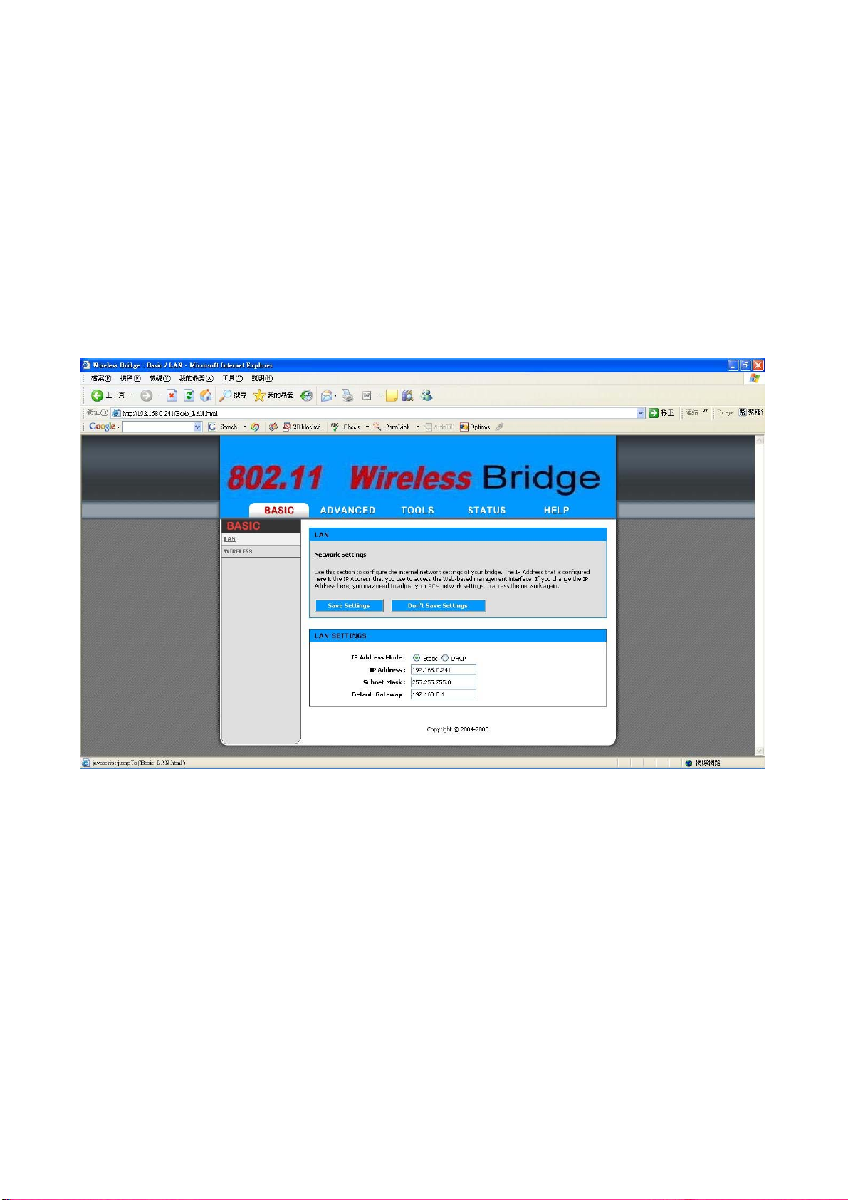
2.4.3 Set Operating Mode, IP Address, Subnet Mask, Default Route IP,
DNS Server IP of OW-2000
► LAN Settings
These are the settings of the LAN (Local Area Network) interface for the Access
Point. The Access Point's local network (LAN) settings are configured based on
the IP Address and Subnet Mask assigned in this section. The IP address is also
used to access this Web-based management interface. This option is available in
the “/BASIC/LAN/” page as shown in Figure 2-7.
Figure 2-7
► Get LAN IP From
Choose "DHCP (Dynamic)" if your router supports DHCP and you want the
router to assign an IP address to the CB. In this case, you do not need to fill in
the following fields. Choose "Static IP (Manual)" if your router does not support
DHCP or if for any other reason you need to assign a fixed address to the CB. In
this case, you must also configure the following fields.
13
Page 77

► IP Address
The IP address of the CB on the local area network. Assign any unused IP
address in the range of IP addresses available for the LAN. For example,
192.168.0.1.
► Subnet Mask
The subnet mask of the local area network.
► Gateway
The IP address of the router on the local area network.
► Local Domain Name
This entry is optional. Enter a domain name for the local network. The CB's
DHCP server will give this domain name to the computers on the wireless LAN.
So, for example, if you enter mynetwork.net here, and you have a wireless
laptop with a name of chris, that laptop will be known as chris.mynetwork.net.
Note, however, if the CB's settings specify "DHCP (Dynamic)" Address, and the
router's DHCP server assigns a domain name to the CB, that domain name will
override any name you enter here.
2.4.4 Set Wireless Encryption for Wireless Interface
The OW-2000 supports 64-bit and 128-bit WEP encryption.
For 64-bit WEP encryption, an encryption key is 10 hexadecimal characters
(0-9 and A-F) or 5 ASCII characters.
For 128-bit WEP encryption, an encryption key is 26 hexadecimal characters or
13 ASCII characters.
Modify the WEP encryption parameters on the web page
“/BASIC/WIRELESS/WIRELESS SECURITY MODE”. Choice “WEP” Enter
1~15 characters into the WEP Key field, than click Save Setting ,Reboot the
Device.
14
Page 78

2.4.5 Change Supervisor Account & Password
Enter the TOOLS > ADMIN page. Figure 2-8 below shows the TOOLS/
ADMIN page.
Figure 2-8
ADMIN PASSWORD
►
Change the ADMIN PASSWORD’s user name and password in the ADMIN
PASSWORD Account field, and click Save Setting ,than Reboot the Device.
to take effect on the previous configuration changes.
15
Page 79

2.4.6 Upgrade the Firmware
► Update the Firmware
Enter the TOOLS > FIRMWARE page as shown in Figure 2-9 to upgrade
OW-2000. Here, user must select which file you want to upgrade it (Program
image), then click Upload button to start the upgrade process.
Hint: It takes about 1 min, to complete the restart process.
Figure 2-9
Caution The Part 15 radio device operates on a non-interference basis with
other devices operating at this frequency when using integrated antennas. Any
changes or modification to the product not expressly approved by RUBY TECH
Corporation could void the user's authority to operate this device.
Caution To meet regulatory restrictions and the safety of the installation, RUBY TECH Corporation strongly
16
Page 80

recommends this product to be professionally installed.
17
 Loading...