

Page 1

RTX9440 TYPE APPROVAL USER GUIDE 1.3
Proprietary and Confidential
Type Approval User Guide for
RTX9440
Quick start guide
Installation & Configura t i on
Technical Reference Document
Version 1.3
© Nov-2019 RTX A/S, Denmark
Page 2

RTX9440 TYPE APPROVAL USER GUIDE 1.3
Proprietary and Confidential
Trademarks
RTX and the combinations of its logo thereof are trademarks of RTX A/S, Denmark.
Other product names used in this publication are for identification purposes and maybe the trademarks of their
respective companies.
Disclaimer
The contents of this document are provided about RTX products. RTX makes no representations with respect to
completeness or accuracy of the contents of this publication and reserves the right to make changes to product
descriptions, usage, etc., at any time without notice. No license, whether express, implied, to any intellectual property
rights are granted by this publication
Confidentiality
This document should be regarded as confidential, unauthorized copying is not allowed
© Nov-2019 RTX A/S, Denmark, All rights reserved
http://www.rtx.dk
Page 3

RTX9440 TYPE APPROVAL USER GUIDE 1.3
Proprietary and Confidential
Table of Contents
Type Approval User Guide for RTX9440 ............................................................................................................................. 1
1 About This Document ................................................................................................................................................. 4
1.1 Important Assumptions ..................................................................................................................................... 4
1.2 Abbreviations .................................................................................................................................................... 4
1.3 Document History ............................................................................................................................................. 4
1.4 Documentation Feedback ................................................................................................................................. 4
2 Introduction – System Overview ................................................................................................................................ 5
2.1 Hardware Setup ................................................................................................................................................ 5
2.2 Components of SME VoIP System ..................................................................................................................... 5
2.2.1 RTX Base Stations .......................................................................................................................................... 6
2.2.2 SME VoIP Administration Server/Software ................................................................................................... 6
2.2.3 RTX Wireless Handset ................................................................................................................................... 6
2.3 Wireless Bands .................................................................................................................................................. 6
2.4 System Capacity (in Summary) .......................................................................................................................... 6
2.5 Advantages of SME VoIP System ....................................................................................................................... 7
3 Installation of Base Stations/Repeater ....................................................................................................................... 8
3.1 Package – Contents/Damage Inspection ........................................................................................................... 8
3.2 RTX Base Station Mechanics ............................................................................................................................. 9
3.3 RTX Base Unit – Reset feature ......................................................................................................................... 10
3.4 Find IP of Base Station ..................................................................................................................................... 11
3.4.1 Using handset Find IP feature ..................................................................................................................... 11
3.4.2 Using browser IPDECT ................................................................................................................................. 11
3.5 Login to Base SME Configuration Interface ..................................................................................................... 11
4 Making Handset Ready ............................................................................................................................................. 12
4.1 Package – Contents/Damage Inspection ......................................................................................................... 12
4.2 Before Using the Phone .................................................................................................................................. 13
Page 4
RTX9440 TYPE APPROVAL USER GUIDE 1.3 4 |
Proprietary and Confidential
1 About This Document
This document describes the installation and configuration of the Cisco VoIP System (RTX9440 base, RTX864x or
RTX8440 handset).
1.1 Important Assumptions
This document was written with the following assumptions in mind:
1) You understand network deployment in general
2) You have working knowledge of basic TCP/IP/SIP protocols, Network Address Translation, etc...
3) A proper site survey has been performed, and the administrator have access to these plans
1.2 Abbreviations
For this document, the following abbreviations hold:
DHCP: Dynamic Host Configuration Protocol
DNS: Domain Name Server
HTTP(S): Hyper Text Transfer Protocol (Secure)
(T)FTP: (Trivial) File Transfer Protocol
IOS: Internetworking Operating System
PCMA: A-law Pulse Code Modulation
PCMU: mu-law Pulse Code Modulation
PoE: Power over Ethernet
RTP: Real-time Transport Protocol
RPORT: Response Port (Refer to RFC3581 for details)
SIP: Session Initiation Protocol
SME: Small and Medium scale Enterprise
VLAN: Virtual Local Access Network
TOS: Type of Service (policy based routing)
URL: Uniform Resource Locator
UA: User Agent
1.3 Document History
REVISION
AUTHOR
ISSUE DATE
COMMENTS
0.1
OHO
08-Jan-2019
First Draft
1.0
OHO
14-05-2019
Updated after review w CAP
1.1
OHO
03-06-2019
Update regarding mounting height
1.2
TWL
6-Nov-2019
Update the FCC warning message
1.3
TWL
7-Nov-2019
Update the ISEDC warning message
1.4 Documentation Feedback
We always strive to produce the best and we also value your comments and suggestions about our documentation. If
you have any comments about this guide, please enter them through the Feedback link on the RTX website. We will
use your feedback to improve the documentation.
Page 5
RTX9440 TYPE APPROVAL USER GUIDE 1.3 5 |
Proprietary and Confidential
2 Introduction – System Overview
In a typical telephony system, the network setup is the interconnection between Base-stations, “NAT” routers,
repeaters, portable parts, etc. The back-bone of the network depends on the deployment scenario, but a ring or hub
topology is used. The network has centralized monitoring, and maintenance system.
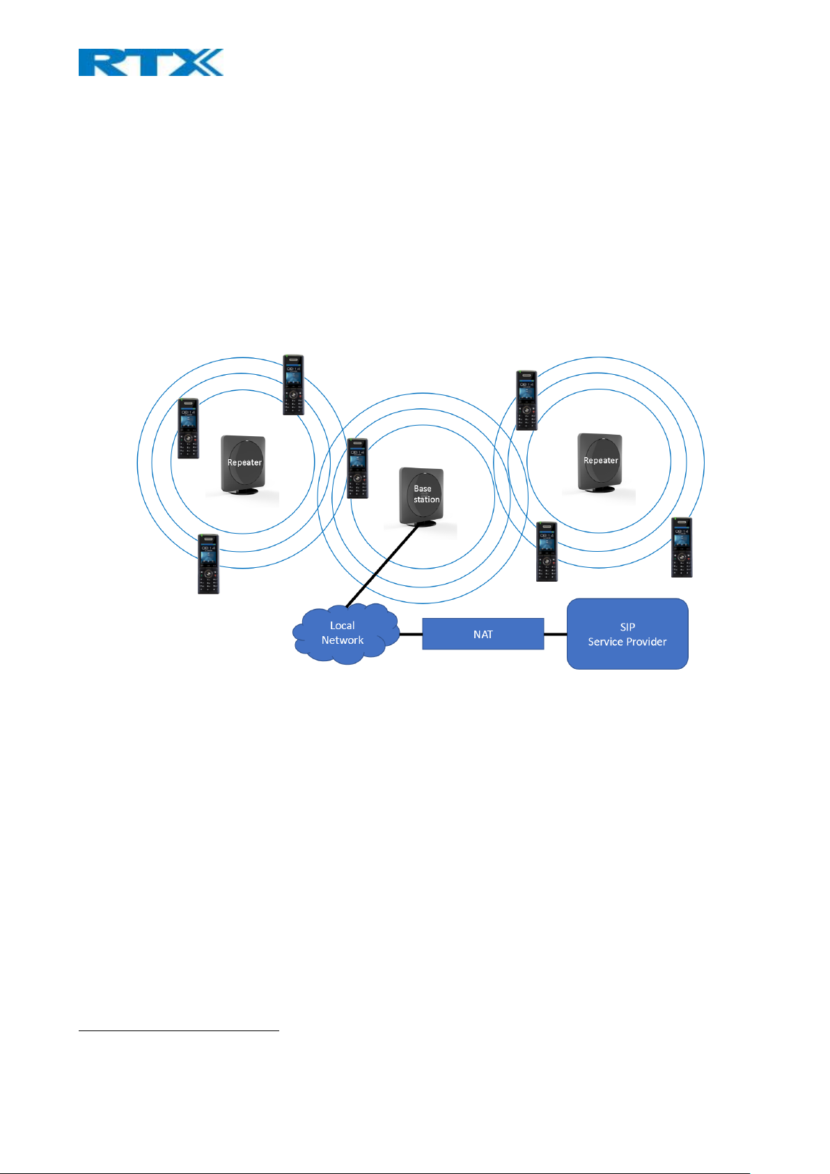
In the RTX9440 based system there is only one base station in the network. Up to 30 handsets (RTX864x or RTX8440
handset) can be registered on the base station. The system can be extended with up to 6 of the supported IP DECT
CAT-IQ repeaters RTX4026. System setup is illustrated below.
Based on PoE interface the base station is easy to install without additional wires other than the LAN cable for power.
The following figure gives a graphical overview of the architecture of the SME VoIP single cell System:
2.1 Hardware Setup
SME network hardware setup can be deployed as follows:
The RTX9440 base-station is connected via Layer 3 and/or VLAN Aware Router depending on the deployment
requirements. The Layer 3 router implements the switching function.
The base-station should be mounted on a wall in a height less than 2 meters. Radio coverage can be extended using
repeaters that are separated from each other by up to 50m indoor1 (300m outdoor). Repeaters are range extenders
and cannot be used to solve local call capacity issues.
The base-station antenna mechanism is based on space diversity feature which improves coverage. The base-station
uses complete DECT MAC protocol layer and IP media stream audio encoding feature to provide up to 10
simultaneous calls.
2.2 Components of SME VoIP System
RTX SME VoIP system consists of (but not limited to) the following components:
1
Measured with European DECT radio and depends on local building layout and material
Page 6

RTX9440 TYPE APPROVAL USER GUIDE 1.3 6 |
Proprietary and Confidential
• At least one RTX Base Station is connected over an IP network and using DECT as air-core interface.
(The RTX9440 is a single cell base station, so in a setup with the RTX9440 base station only one base station is
connected to the IP network).
• RTX IP DECT wireless Handset.
• RTX SME VoIP Configuration Interface; is a management interface for SME VoIP Wireless Solution. It runs on all IP
DECT Base stations. Each Base station has its own unique settings.
2.2.1 RTX Base Stations
The Base Station converts IP protocol to DECT protocol and transmits the traffic to and from the end-nodes (i.e.
wireless handsets) over a channel. It has 12 available channels.
2.2.2 SME VoIP Administration Server/Software
This server is referred to as SME VoIP Configuration Interface.
The SME VoIP Configuration Interface is a web based administration page used for configuration and programming of
the base station and relevant network end-nodes. E.g. handsets can be registered or de-registered from the system
using this interface.
The configuration interface can be used as a setup tool for software or firmware download to base stations, repeaters
and handsets. Further, it is used to check relevant system logs that can be useful to administrator. These logs can be
used to troubleshoot the system when the system faces unforeseen operational issues.
2.2.3 RTX Wireless Handset
The handset is a lightweight, ergonomically, and portable unit compatible with Wideband Audio (G.722), DECT, GAP
standard, CAT-iq audio compliant.
The handset includes color display with graphical user interface. It can also provide the subscriber with most of the
features available for a wired phone, in addition to its roaming and handover capabilities. Refer to the relevant
handset manuals for full details handset features.
2.3 Wireless Bands
The bands supported in the SME VoIP are summarized as follows:
Frequency bands:
1880 – 1930 MHz (DECT)
1880 – 1900 MHz (10 carriers) Europe/ETSI
1910 – 1930 MHz (10 carriers) LATAM
1920 – 1930 MHz (5 carriers) US
Transmit Power: 23.7 dBm in Europe mode.
2.4 System Capacity (in Summary)
SME network capacity of relevant components can be summarized as follows:
DESCRIPTION
CAPACITY
Min ## of Bases Single Cell Setup
1
Max ## of Bases in Multi-cell Setup (configurable)
NA – RTX9440 is a single cell system
Single/Multi Cell Setup: Max ## of Repeaters
1 base and up to 6 repeaters
RTX9440 is a single cell system, so no
multicell setup available.
Page 7

RTX9440 TYPE APPROVAL USER GUIDE 1.3 7 |
Proprietary and Confidential
Multi-cell Setup: Total Max ## of Repeaters
NA – RTX9440 is a single cell system
Max ## of Users (SIP registrations) per Base
30
Max ## of Users per SME VoIP System
limited to 30
Multi-cell Setup: Max ## of Synchronization levels
NA – RTX9440 is a single cell system
Single Cell Setup: Max ## Simultaneous Calls
10 per Base station
Multi-cell Setup: Max ## of Calls
NA – RTX9440 is a single cell system
Total Max ## Simultaneous Calls (Multi-cell Setup)
NA – RTX9440 is a single cell system
Repeater: Max ## of Calls (Narrow band)
5
Repeater: Max ## of Calls (G722)
2
Quick Definitions
Single Cell Setup: SME telephony network composed of one base station
Multi-cell Setup: Telephony network that consists of more than one base station
Synchronization Level: Is the air core interface between two base stations.
2.5 Advantages of SME VoIP System
They include (but not limited to):
1. Simplicity. Integrating functionalities leads to reduced maintenance and troubleshooting, and significant cost
reductions.
2. Flexibility. Single network architecture can be employed and managed. Furthermore, the architecture is amenable
to different deployment scenarios, including Isolated buildings for in-building coverage, location with co-located
partners, and large to medium scale enterprises deployment for wide coverage.
3. Scalability. SME network architecture can easily be scaled to the required size depending on customer requirement.
4. Performance. The integration of different network functionalities leads to the collapse of the protocol stack in a
single network element and thereby eliminates transmission delays between network elements and reduces the call
setup time and packet fragmentation and aggregation delays.
Page 8

RTX9440 TYPE APPROVAL USER GUIDE 1.3 8 |
Proprietary and Confidential
3 Installation of Base Stations/Repeater
After planning the network, next is to determine the proper places or location the relevant base station and potential
repeaters will be installed. Therefore, we briefly describe the how to install the base station in this chapter.
3.1 Package – Contents/Damage Inspection
Before Package Is Opened:
Examine the shipping package for evidence of physical damage or mishandling prior to opening. If there is a proof of
mishandling prior to opening, you must report it to the relevant support center of the regional representative or
operator.
Contents of Package:
Make sure all relevant components are available in the package before proceeding to the next step.
Every shipped base unit package/box contains the following items:
• 3 x mounting screws and 1 x Anchor
• 1 x Plastic Wall mount
• Base unit
Page 9

RTX9440 TYPE APPROVAL USER GUIDE 1.3 9 |
Proprietary and Confidential
Damage Inspection:
The following are the recommended procedure for you to use for inspection:
1. Examine all relevant components for damage.
2. Make a “defective on arrival – DOA” report or RMA to the operator. Do not move the shipping carton until
the operator has examined it. If possible, send pictures of the damage. The operator/regional representative
will initiate the necessary procedure to process this RMA. They will guide the network administrator on how
to return the damaged package if necessary.
3. If no damage is found, then unwrap all the components and dispose of empty package/carton(s) in
accordance with country specific environmental regulations.
3.2 RTX Base Station Mechanics
The base station front end shows an LED indicator that signals different functional states of the base unit and
occasionally of the overall network. The indicator is off when the base unit is not powered.
Page 10

RTX9440 TYPE APPROVAL USER GUIDE 1.3 10 |
Proprietary and Confidential
The table below summarizes the various LED states:
LED STATE
STATE
UNLIT
No power in unit
UNLIT/SOLID RED
Error condition
BLINKING GREEN
Initialization
SOLID RED
Factory reset warning or long press in BS reset button
BLINKING RED
Factory setting in progress
SOLID GREEN
Ethernet connection available (Normal operation)
BLINKING RED
Ethernet connect not available OR handset de/registration failed
SOLID RED
Critical error (can only be identified by RTX Engineers). Symptoms include no
system/SIP debug logs are logged, etc.
ORANGE
Press reset button of base station.
BLINKING ORANGE
No IP address received
3.3 RTX Base Unit – Reset feature
It is possible to restart or reset the base station unit by pressing a knob at the bottom edge of the unit. Alternatively, it
can be reset from the SME Configuration Interface. We do not recommend this; but unplugging and plugging the
Ethernet cable back to the PoE port of the base station also resets the base unit.
Page 11

RTX9440 TYPE APPROVAL USER GUIDE 1.3 11 |
Proprietary and Confidential
3.4 Find IP of Base Station
To find IP of the installed base station two methods can be used; Using handset Find IP feature or browser IPDECT
feature.
3.4.1 Using handset Find IP feature
On the handset press “Menu” key followed by the keys: *47* to get the handset into find bases menu. The handset
will now scan for the RTX9440 base. Depending on the amount of powered on bases with active radios and the
distance to the base it can take up to minutes to find a base.
- Use the cursor down/up to select the base MAC address for the base
- The base IP address will be shown in the display
The feature is also used for deployment.
3.4.2 Using browser IPDECT
Open any standard browser and enter the address:
http://ipdect<MAC-Address-Base-Station>
for e.g. http://ipdect00087B00AA10. This will retrieve the HTTP Web Server page from the base station with hardware
address 00087B00AA10.
This feature requires an available DNS server.
3.5 Login to Base SME Configuration Interface
1. Connect the Base station to a private network via standard Ethernet cable (CAT-5).
2. Use the IP find menu in the handset (Menu * 4 7 *) to determine the IP-address of the base station by matching
the MAC address on the back of the base station with the MAC address list in the handset.
3. On the Login page, enter your authenticating credentials (i.e. username and password). By default, the username
and password are admin. Click OK button.
4. Once you have authenticated, the browser will display front end of the SME Configuration Interface. The front end
will show relevant information of the base station.
Screenshot:
Page 12

RTX9440 TYPE APPROVAL USER GUIDE 1.3 12 |
Proprietary and Confidential
4 Making Handset Ready
In this chapter, we briefly describe how to prepare the handset for use, install, insert and charge new batteries. Please
refer to an accompanying Handset User Guide for more information of the features available in the Handset.
4.1 Package – Contents/Damage Inspection
Before Package Is Opened:
Examine the shipping package for evidence of physical damage or mishandling prior to opening. If there is a proof of
mishandling prior to opening, you must report it to the relevant support center of the regional representative or
operator.
Contents of Package:
Make sure all relevant components are available in the package before proceeding to the next step.
Every shipped base unit package/box contains the following items:
• 1 x Handset hook
• 1 x A/C Adaptor
• 1 x Battery
• 1 x charger
• 1 x Handset Unit
• 1 x Battery cover,
• 1 x Belt hook
Page 13

RTX9440 TYPE APPROVAL USER GUIDE 1.3 13 |
Proprietary and Confidential
Damage Inspection:
The following are the recommended procedure for you to use for inspection:
1. Examine all relevant components for damage.
2. Make a “defective on arrival – DOA” report or RMA to the operator. Do not move the shipping carton until
the operator has examined it. The operator/regional representative will initiate the necessary procedure to
process this RMA. They will guide the network administrator on how to return the damaged package if
necessary.
3. If no damage is found, then unwrap all the components and dispose of empty package/carton(s) in
accordance with country specific environmental regulations.
4.2 Before Using the Phone
Here are the pre-cautions users should read before using the Handset:
Installing the Battery
1. Never dispose battery in fires, otherwise it will explode.
2. Never replace the batteries in potentially explosive environments, e.g. close to inflammable liquids/ gases.
3. ONLY use approved batteries and chargers from the vendor or operator.
4. Do not disassemble, customize, or short circuit the battery
Closing Back Cover
1. Slide the top of the battery cover into the designated slot of the handset (see step 1 in below drawing)
2. Press the bottom of the battery cover onto the handset (see step 2 in below drawing)
3. Move the lock pin to “locked position” (see step 3 in below drawing)
Replace Battery
Remove Back Cover from Handset. Remove the old battery and replace with a new one.
Page 14

RTX9440 TYPE APPROVAL USER GUIDE 1.3 14 |
Proprietary and Confidential
Using the Charger
Each handset is charged using a handset charger. The charger is a compact desktop unit designed to charge and
automatically maintain the correct battery charge levels and voltage.
The charger Handset is powered by AC supply from 110-240VAC that supplies 5.0VDC at 2A.
When charging the battery for the first time, it is necessary to leave the handset in the charger for at least 10 hours
before the battery is fully charged and the handset ready for use.
Handset in the Charger
For correct charging, ensure that the room temperature is between 5°C and 25°C/41°F and 77°F. Do not place the
handset in direct sunlight. The battery has a built-in heat sensor which will stop charging if the battery temperature is
too high.
If the handset is turned off when placed in charger, only the LED indicates the charging. When handset is turned off,
the LED flashes at a low frequency while charging and lights constantly when the charging is finished. There will be
response for incoming calls.
If the handset is turned on when charging, the display shows the charging status.
Handset Serial Number
The serial number (IPEI/IPUI number) of each handset is found either on a label, which is placed behind the battery, or
on the packaging label. First, lift off handset back cover and lift the battery and read the serial number.
The serial number is needed to enable service to the handset. It must be programmed into the system database via
the SME VoIP Configuration interface.
Page 15

RTX9440 TYPE APPROVAL USER GUIDE 1.3 15 |
Proprietary and Confidential
Handset Battery
There is a danger of explosion if the battery is replaced incorrectly. Use only recommended battery from Dong Guan
DRN New Energy Co. LTD. (Cell model no.: RTR001F05 - Li-ion 3.7V 1100mAh 4.2Wh).
CAUTION
RISK OF EXPLOSION IF BATTERY IS REPLACED BY AN INCORRECT TYPE.
DISPOSE OF USED BATTERIES ACCORDING TO THE INSTRUCTIONS
For countries in the European Union
Be sure to dispose of these products as well as its packing material in an environmentally compatible
way.
Electrical equipment, including the battery, should not be disposed of as municipal waste.
These products should be taken to a designated facility where the best available treatment, recovery and
recycling techniques are available.
For countries outside the European Union
Disposal of electrical and electronic products in countries outside the European Union should be done in line with the
local regulations. If no arrangement has been made with NEC or your supplier, please contact the local authorities for
further information.
CE
Handset CP-6825-K9, CP-6825-RGD-K9; charger CP-6825-HC; base DBS-110-3PC-CE-K9 are in compliance with the
essential requirements and other relevant provisions of below.
2011/65/EU
Restriction of the use of certain hazardous substances in electrical and electronic equipment (RoHS)
1907/2006
Registration, Evaluation, Authorization and Restriction of Chemicals (REACH)
2012/19/EU
Amending Directive 2002/96/EC on Waste Electrical and Electronic Equipment (WEEE)
Page 16

RTX9440 TYPE APPROVAL USER GUIDE 1.3 16 |
Proprietary and Confidential
2014/35/EU
Low Voltage Directive (LVD)
2014/30/EU
Electromagnetic Compatibility Directive (EMC)
2009/125/EC
Eco-design requirements for Energy-related Products (ErP)
2014/53/EU
Radio Equipment Directive (RED)
Adaptor
Base DBS-110-3PC-CE-K9 and
Charger CP-6825-HC, is dedicated for Handset CP-6825-K9, CP-6825-RGD-K9 and needs the following Power Supply
Units:
PSU Europe
- TenPao (Model S010WV0500200) – efficiency level VI (rating I/P:AC 100-240V, 0.4A; O/P: DC 5V, 2A).
PSU United State
- TenPao (Model S010WU0500200) – efficiency level VI (rating I/P:AC 100-240V, 0.4A; O/P: DC 5V, 2A).
PSU United Kingdom
- TenPao (Model S010WB0500200) – efficiency level VI (rating I/P:AC 100-240V, 0.4A; O/P: DC 5V, 2A).
PSU Australia
- TenPao (Model S010WS0500200) – efficiency level VI (rating I/P:AC 100-240V, 0.4A; O/P: DC 5V, 2A).
PSU WW
- TenPao (Model S008ACM0500100 with EU, UK,US, AUS plugs) – efficiency level VI (rating I/P:AC 100-240V, 0.3A; O/P:
DC 5V, 1A).
- TenPao (Model S008ACM0500200 with EU, UK,US, AUS plugs) – efficiency level VI (rating I/P:AC 100-240V, 0.3A; O/P:
DC 5V, 2A).
FCC Warning
This equipment has been tested and found to comply with the limits for a Class B digital device, pursuant to part 15
of the FCC Rules. These limits are designed to provide reasonable protection against harmful interference in a
residential installation. This equipment generates, uses and can radiate radio frequency energy and, if not installed and
used in accordance with the instructions, may cause harmful interference to radio communications. However, there is no
guarantee that interference will not occur in a particular installation. If this equipment does cause harmful interference
to radio or television reception, which can be determined by turning the equipment off and on, the user is encouraged to
try to correct the interference by one or more of the following measures:
—Reorient or relocate the receiving antenna.
—Increase the separation between the equipment and receiver.
—Connect the equipment into an outlet on a circuit different from that to which the receiver is connected.
—Consult the dealer or an experienced radio/TV technician for help.
Changes or modifications to this equipment not expressly approved by the party responsible for compliance could
void the user’s authority to operate the equipment.
This device complies with part 15 of the FCC Rules. Operation is subject to the following two conditions: (1) This device
may not cause harmful interference, and (2) this device must accept any interference received, including interference
that may cause undesired operation.
For Handset
SAR tests are conducted using standard operating positions accepted by the FCC with device transmitting at its highest
certifed power level in all tested frequency bands, although the SAR is determined at the highest certified power level,
the actual SAR level of the device while operating can be well below the maximum value. Before a new model device
is an available for sale to the public, it must be tested and certifed to the FCC that it does not exceed the exposure
Page 17

RTX9440 TYPE APPROVAL USER GUIDE 1.3 17 |
Proprietary and Confidential
limit established by the FCC, tests for each device are performed in positions and locations as required by the FCC. For
body
worn operation, this model device has been tested and meets the FCC RF exposure guidelines when used with an
accessory designated for this product or when used with an accessory that contains no metal.
For Base
This equipment complies with FCC radiation exposure limits set forth for an uncontrolled environment. This
equipment should be installed and operated with minimum distance 20cm between the radiator& your body. This
transmitter must not be co-located or operating in conjunction with any other antenna or transmitter located or
operating in conjunction with any other antenna or transmitter.
ISEDC Warning
This device contains licence-exempt transmitter(s)/receiver(s) that comply with Innovation, Science and Economic
Development Canada’s licence-exempt RSS(s). Operation is subject to the following two conditions:
1. This device may not cause interference.
2. This device must accept any interference, including interference that may cause undesired operation of the device.
Cet appareil est compatible avec la licence de l’Innovation, la Science et le développement conomique du Canada à
l’exemption des normes RSS. Le fonctionnement est sujet aux deux (2) conditions suivantes :
(1) Cet appareil peut ne pas causer de l’interférence, et
(2) Cet appareil doit accepter l’interférence, incluant de l’interférence qui peut causer un mauvais fonctionnement de cet
appareil.
For Handset
SAR tests are conducted using standard operating positions accepted by the ISEDC with device transmitting at its
highest certifed power level in all tested frequency bands, although the SAR is determined at the highest certified power
level, the actual SAR level of the device while operating can be well below the maximum value. Before a new model
device is an available for sale to the public, it must be tested and certifed to the ISEDC that it does not exceed the
exposure limit established by the ISEDC, tests for each device are performed in positions and locations as required by
the ISEDC. For body worn operation, this model device has been tested and meets the ISEDC RF exposure guidelines
when used with an accessory designated for this product or when used with an accessory that contains no metal.
For Base
This equipment complies with ISEDC radiation exposure limits set forth for an uncontrolled environment. This
equipment should be installed and operated with minimum distance 20cm between the radiator& your body. This
transmitter must not be co-located or operating in conjunction with any other antenna or transmitter located or operating
in conjunction with any other antenna or transmitter.
Pour le combiné
Les tests SAR sont faits en utilisant les normes de positions d’opération acceptées par l’ISEDC avec les appareils
émettant les plus hauts niveaux de puissance certifiés sur toutes les bandes de fréquences, même si le SAR est
déterminé d’être du plus haut niveau de puissance certifié, le niveau SAR actuel de l’appareil peut être sous la valeur
maximale de fonctionnement. Avant qu’un nouveau modèle d’appareil ne soit disponible pour la vente au public, celuici doit être soumis à des tests de certification par l’ISEDC lesquels n’excèdent aucunement la limite d’exposition issue
par l’ISEDC, lesquels sont des tests effectués sur chaque appareil dans des positions et endroits requis par l’ISEDC.
Pour l’usure de construction de ce modèle d’appareil, celui-ci a été testé et rencontre les lignes directrices émises par
l’ISEDC RF pour l’exposition, lorsqu’il est utilisé avec un accessoire conçu pour ce produit ou utilisé avec un
accessoire qui ne contient aucun métal.
Pour la base
Cet équipement est conforme avec les limites d’exposition à la radiation de l’ISEDC émises dans un environnement
contrôlé. Cet équipement devrait être installé et fonctionnel avec un minimum de distance entre le radiateur et votre
corps d’au moins 20 cm. Ce transmetteur ne doit pas être co-situé près d’une autre antenne ou en conjonction avec un
autre transmetteur.
Page 18

RTX9440 TYPE APPROVAL USER GUIDE 1.3 18 |
Proprietary and Confidential
This Class B digital apparatus complies with Canadian ICES-003.
Cet appareille numérique de classe B est conforme aux normes canadiennes ICES-003.
 Loading...