

Page 1
User’s Manual V1.00 RTX2300 – Smart ATE 1
RTX2300
Smart ATE
User Manual
Version: 1.00
Page 2

User’s Manual V1.00 RTX2300 – Smart ATE 2
General
Information contained in t his document is subject to change without notice. RTX A/S makes
no warranty of any kind regarding this material, in cluding, but n ot limited to, th e implied
warranties of merchantability and fitness for a particular purpose. RTX A/S shall not be
liable for errors contained herein or for incidental or consequential damages about the
furnishings, performance, or use of this material.
Warranty
This instrument is warranted against defects in material and Workman ship for a period of
one year from date of shipment. During the warranty period, RTX A/S will at its option,
either repair or replace products, which prove to be defective. For warranty service or
repair, this product must be returned to a service facility designated by RTX A/S. Buyer
shall prepay shipping charges to RTX A/S and RTX A/S shall pay shipping charges, duties,
and taxes for products returned to RTX A/S from another country. RTX A/S warrants that
its software and firmware designated by RTX A/S for use with an instrument will execute
its programming instructions when properly installed on that instrument. RTX A/S does not
warrant that the operation of the instrument or firmware will be uninterrupted or error
free.
Limitation of Warranty
The foregoing warranty shall not apply to defects resulting from improper or inadequate
maintenance by Buyer, Buyer-supplied software or interfacing, unauthorized modification
or misuse, operation outside of the environmental specifications for the product, or improper site preparation or maintenance.
NO OTHER WARRANTY IS EXPRESSED OR IMPLIED.RTX A/S SPECIFICALLY DISCLAIMS
THE IMPLIED WARRANTIES OF MERCHANTABILITY AND FITNESS FOR A PARTICULAR
PURPOSE.
Page 3

User’s Manual V1.00 RTX2300 – Smart ATE 3
General information
This document and the information contained, is property of RTX A/S, Denmark.
Unauthorized copying is not allowed. The information in this document is believed to be
correct at the time of writing. RTX A/S reserves the right at any time to change said
content, circuitry and specifications.
The general safety precautions, according to the information provided in the RTX2300
User’s Manual, must be observed during all phases of operation. RTX A/S assumes no
liability for the customer’s failure to comply with th ese requirements.
The purpose of the document is to provide guidance to users of the RTX2300 Smart ATE.
The User’s manual describes general functions of the test equipment and describes the use
of the related Windows® based interface, as well as interfacing with a production
application program.
Page 4
User’s Manual V1.00 RTX2300 – Smart ATE 4
Safety information
The following general safety precautions must be observed during all phases of operation
and service of this instrument. Failure to comply with these precautions or with specific
warnings elsewhere in this manual violates safety standards of design, manufacture, and
intended use of the instrument. RTX A/S assumes no liability for the customer’s failure to
comply with these requirements.
DO NOT operate the product in an explosive atmosphere or in the presence of flammable gasses or fumes.
DO NOT use repaired fuses or sh ort-circuited fuse holders: For continued
protection against fire, replace the line fuse(s) only with fuse(s) of the
same voltage and current rating and type.
DO NOT perform procedures involving cover or shield removal unless
you are qualified to do so – it is therefore strongly emphasized here th at
operating personnel must not remove equipment covers or shields.
Procedures involving the removal of covers and shields are for use by
service-trained personnel at RTX A/S only.
Page 5

User’s Manual V1.00 RTX2300 – Smart ATE 5
Electrostatic Discharge
Electrostatic discharge (ESD) can damage electronic test equipment. Working with
electronic components or test equipment sho uld always be performed at a static-safe place.
High Voltage
Some power supplies can generate high voltage, which can damage the all the port of the
unit. To prevent damage to the RTX2300 Smart ATE please make sure that the device is
properly earthed.
Page 6

User’s Manual V1.00 RTX2300 – Smart ATE 6
Documentation information
This User’s Manual contains essential items of information needed for general-purpose use
of the test equipment along with a detailed description for high throughput production
purposes. In t his document yo u will find valua ble informatio n on how to unpack, install and
operate your RTX2300 Smart ATE unit.
The User’s Manual provides programming guidance to users of the RTX2300 Smart ATE
who would like to write their own test programs. A few examples on how to use the DLL
function calls in your source code are also outlined. However, please note that the
examples and code fragments are included for informational reasons only and sho ul d only
be used as a guidance to ease test program development. It is therefore strongly
emphasized here that RTX takes no responsibility for debugging and verification of the
actual test program developed by the customer.
Conventions Used in this Manual
The following text conventions are used in this guide:
Parameter used to represent a parameter, value or data in an entry field
RUN used to represent the text in the Windows® based user interface
Abbreviations Used in this Manual
The following abbreviations are used in this guide:
API Application Programming Interface
ATE Automatic Test Equipment
CCB Customized Connector Block (physically the same as SCB but with
customized connectors)
DECT Digital Enhanced Cordless Telecommunications
DUT Device Under Test
GUI Graphical User Interface
LED Light Emitting Diode
PSU Power Supply Unit
QSK Quick-Swap Kit
REPS RTX EAI Port Server
RF Radio Frequency
SCB Standard Connector Block (PCB with 2 connectors – one 2x25 pin header
and 3x14 pin + 6RF option + 2 pneumatic)
SCPI Standard Commands for Programmable Instruments
SMPS Switch Mode Power Supply
THD Total Harmonic Distortion
DUT Devicenit Under Test
Page 7

User’s Manual V1.00 RTX2300 – Smart ATE 7
CONTENT
1.
GETTING STARTED .............................................................................................................................. 11
A. INTRODUCTION ........................................................................................................................................... 11
B. UNPACKING THE RTX2300 SMART ATE .......................................................................................................... 12
i. Initial Inspection ............................................................................................................................................ 12
ii. Box content .................................................................................................................................................... 12
C. GENERAL OVERVIEW OF THE RTX2300 SMART ATE UNIT ................................................................................... 12
i. Rear Panel Connectors ................................................................................................................................... 12
ii. Internal Connectors ....................................................................................................................................... 14
Shielded Fixture Bay Connectors ......................................................................................................................... 14
Controller Chamber Connectors ......................................................................................................................... 16
iii. Front Panel Functions .................................................................................................................................... 17
D. OVERVIEW OF INSTRUMENTATION AND FUNCTIONAL BLOCKS ................................................................................ 19
i. Digital AC & DC Voltmeter (DVM) .................................................................................................................. 20
ii. Tone Generator .............................................................................................................................................. 20
iii. Signal multiplexer .......................................................................................................................................... 20
iv. GPIO ............................................................................................................................................................... 20
v. Main functional blocks in the RTX2300 .......................................................................................................... 21
Fixture and box control ....................................................................................................................................... 21
Power supply ....................................................................................................................................................... 21
Communication interfaces .................................................................................................................................. 22
Expansion slot USB interfaces ........................................................................................................................ 22
RTX2300 control interface ............................................................................................................................. 22
CCB USB interface .......................................................................................................................................... 22
SCB USB interface .......................................................................................................................................... 22
DUT serial communication configuration ...................................................................................................... 22
E. INSTALLING RTX2300 OPTIONS ..................................................................................................................... 24
i. Installing modules .......................................................................................................................................... 24
ii. Installing Quick-Swap Kit ................................................................................................................................ 25
Installing the fixture bay part of the Quick-Swap Kit ........................................................................................... 25
Installing the fixture part of the Quick-Swap Kit ................................................................................................. 26
iii. Installing a fixture kit ..................................................................................................................................... 28
With QSK installed: ................................................................................................................................................... 28
Without QSK installed: ............................................................................................................................................. 29
F. SYSTEM SETUP AND INSTALLATION OF THE RTX2300 .......................................................................................... 30
i. Connecting the RTX2300 Smart ATE .............................................................................................................. 30
G. INSTALLING THE PC SOFTWARE ...................................................................................................................... 31
i. Installing the RTX2300 Basic Unit SW ............................................................................................................ 33
ii. Installing the RTX2300 USB Bridge Driver ...................................................................................................... 36
iii. Installing the RTX EAI Port Server .................................................................................................................. 37
iv. Installing the RTX2300 DUT UART driver ....................................................................................................... 39
v. Installing the RTX2300 Basic Unit Communication driver .............................................................................. 41
2. RTX2300 BASIC UNIT SW PACKAGE ..................................................................................................... 43
A. INTRODUCTION ........................................................................................................................................... 43
B. CONTENTS OF THE RTX2300 BASIC UNIT SW PACKAGE ..................................................................................... 43
i. Windows applications .................................................................................................................................... 43
ii. Documentation .............................................................................................................................................. 44
iii. Source Code and Binaries .............................................................................................................................. 44
C. RTX EAI PORT SERVER ................................................................................................................................. 44
i. Setup - General Page Overview ..................................................................................................................... 45
ii. Setup - UART Page Overview ......................................................................................................................... 46
iii. Setup – Socket Page Overview ....................................................................................................................... 47
iv. Status Window Overview ............................................................................................................................... 48
D. RTX2300 DETECTIVE DEBUG APPLICATION ....................................................................................................... 48
i. I/O Page Overview ......................................................................................................................................... 48
Output pane ........................................................................................................................................................ 51
Input pane ........................................................................................................................................................... 52
Page 8

User’s Manual V1.00 RTX2300 – Smart ATE 8
ii. Ad/Da Page Overview .................................................................................................................................... 52
DAC ...................................................................................................................................................................... 53
ADC ...................................................................................................................................................................... 54
iii. Audio Page Overview ..................................................................................................................................... 54
Level .................................................................................................................................................................... 55
Distortion ............................................................................................................................................................ 55
Generator ............................................................................................................................................................ 56
iv. PWM Page Overview ..................................................................................................................................... 56
v. DUT Page Overview ....................................................................................................................................... 57
SCB bus ................................................................................................................................................................ 58
USB enable .......................................................................................................................................................... 58
DUT SerCom ........................................................................................................................................................ 58
vi. Power Supply Page Overview ........................................................................................................................ 58
Voltage ................................................................................................................................................................ 58
Current ................................................................................................................................................................ 58
Current range ...................................................................................................................................................... 59
PSU Selection ...................................................................................................................................................... 59
Measurements .................................................................................................................................................... 59
vii. General Page Overview .................................................................................................................................. 60
Status .................................................................................................................................................................. 61
Access Mode ....................................................................................................................................................... 61
viii. Info Page Overview ........................................................................................................................................ 61
Serial number ...................................................................................................................................................... 63
Insert/CCB Info .................................................................................................................................................... 64
ix. Firmware Page Overview ............................................................................................................................... 65
Firmware information ......................................................................................................................................... 66
Firmware update ................................................................................................................................................. 66
x. User Data Page Overview............................................................................................................................... 67
xi. Logs Page Overview ....................................................................................................................................... 68
Logs ..................................................................................................................................................................... 68
Errors ................................................................................................................................................................... 68
xii. Settings Page Overview .................................................................................................................................. 69
3. USING THE RTX2300 WINDOWS SW .................................................................................................... 70
A. INTRODUCTION ........................................................................................................................................... 70
B. USING THE RTX2300 DETECTIVE DEBUG APPLICATION ....................................................................................... 70
i. Configuring the RTX EAI Port Server (REPS) ................................................................................................... 70
ii. Launching and use of the RTX2300 Detective application ............................................................................. 74
Launching RTX2300 Detective ............................................................................................................................. 74
Using the RTX2300 Detective application for debugging purposes .................................................................... 76
C. PERFORMING UNIT TESTS WITH THE RTX2300 .................................................................................................. 77
4. RTX2300 SMART ATE OPTIONS ........................................................................................................... 81
A. MODULES .................................................................................................................................................. 81
i. Programmable PSU Module ........................................................................................................................... 82
ii. Frequency Counter Module ........................................................................................................................... 82
Standard Frequency Counter .............................................................................................................................. 83
High-Stabilty Frequency Counter ........................................................................................................................ 83
B. QUICK-SWAP KIT (QSK) ............................................................................................................................... 83
i. Fixture bay part .............................................................................................................................................. 83
ii. Fixture part .................................................................................................................................................... 84
C. FIXTURE KITS .............................................................................................................................................. 84
i. Standard Fixture Kit with pneumatic slide ..................................................................................................... 84
ii. Standard Fixture Kit without pneumatic slide ................................................................................................ 85
D. CONNECTIVITY OPTIONS ................................................................................................................................ 85
i. DUT Interface ................................................................................................................................................. 85
SPI interface to DUT ............................................................................................................................................ 85
I2C interface to DUT ............................................................................................................................................ 86
ii. Rear panel ...................................................................................................................................................... 86
RJ45 connection .................................................................................................................................................. 86
Page 9

User’s Manual V1.00 RTX2300 – Smart ATE 9
5. FIXTURE BAY CONNECTOR INTERFACES ............................................................................................... 87
A. STANDARD FIXTURE BAY CONNECTORS ............................................................................................................ 88
i. SCB ................................................................................................................................................................. 89
ii. CCB ................................................................................................................................................................. 89
B. QUICK-SWAP KIT CONNECTORS – FIXTURE BAY PART (OPTION) ............................................................................ 89
i. SCB ................................................................................................................................................................. 90
ii. CCB ................................................................................................................................................................. 91
C. QUICK-SWAP KIT CONNECTORS – FIXTURE PART (OPTION) .................................................................................. 91
i. SCB ................................................................................................................................................................. 93
ii. CCB ................................................................................................................................................................. 93
D. SCB INTERFACE PIN OVERVIEW ...................................................................................................................... 94
E. CCB INTERFACE PIN OVERVIEW ...................................................................................................................... 97
F. ELECTRICAL CHARACTERISTICS FOR FIXTURE INTERFACES .................................................................................... 100
6. RTX2300 CUSTOMIZATION ................................................................................................................ 102
A. CONTROLLER CHAMBER CUSTOMIZATION INTERFACE ........................................................................................ 102
B. CUSTOMIZATION INTERFACE PIN OVERVIEW ................................................................................................... 103
i. Customization Output Connector Pin Overview (J402) ............................................................................... 104
ii. Customization Input Connector Pin Overview (J400) .................................................................................. 106
iii. Customization Input Connector Pin Overview (J401) .................................................................................. 108
iv. Customization Input Connector Pin Overview (J403) .................................................................................. 110
v. External AUX Interface Connector (J1205) ................................................................................................... 112
C. CREATING A CUSTOMIZATION BOARD FOR THE RTX2300 .................................................................................. 113
i. Customization board - dimensions and connector types ............................................................................. 114
Board dimensions and connector location ........................................................................................................ 114
Connector types ................................................................................................................................................ 114
ii. Reference PADS file ..................................................................................................................................... 115
D. CUSTOMIZATION OF FIXTURES FOR THE RTX2300 ............................................................................................ 115
7. IMPLEMENTING RTX2300 TEST PROGRAMS ...................................................................................... 118
A. RTX2300 API OVERVIEW ........................................................................................................................... 118
B. HOW TO IMPLEMENT A RTX2300 TEST PROGRAM ........................................................................................... 120
i. Example 1 – simple test program ................................................................................................................. 120
ii. Example 2 – test program controlling multiple RTX2300 units .................................................................... 122
iii. Example 3 – firmware update program ....................................................................................................... 124
C. DYNAMIC LINK LIBRARY INTERFACING ............................................................................................................ 126
i. Dynamic Link Library Interface Description ................................................................................................. 126
Calling Convention ............................................................................................................................................ 126
Explicit DLL Linking ............................................................................................................................................ 127
Implicit DLL Linking ............................................................................................................................................ 127
8. SPECIFICATIONS AND CHARACTERISTICS ........................................................................................... 128
A. INTRODUCTION ......................................................................................................................................... 128
B. RTX2300 SMART ATE BASIC UNIT ............................................................................................................... 128
i. D/A channels ................................................................................................................................................ 128
ii. Tone generator ............................................................................................................................................ 128
iii. Audio buffer ................................................................................................................................................. 129
iv. A/D channels ................................................................................................................................................ 130
v. Audio measurement .................................................................................................................................... 131
vi. GPIO ............................................................................................................................................................. 132
vii. General Specifications.................................................................................................................................. 133
Power supply ..................................................................................................................................................... 133
Mechanical specification ................................................................................................................................... 133
Reliability requirements .................................................................................................................................... 133
Input/output connectors ................................................................................................................................... 134
C. OPTIONAL MODULES .................................................................................................................................. 135
i. Programmable PSU ...................................................................................................................................... 135
ii. Frequency counter ....................................................................................................................................... 136
Page 10

User’s Manual V1.00 RTX2300 – Smart ATE 10
9. MAINTENANCE ................................................................................................................................. 137
A. INTRODUCTION ......................................................................................................................................... 137
B. GENERAL CUSTOMER RESPONSIBILITIES .......................................................................................................... 137
C. OPERATOR MAINTENANCE .......................................................................................................................... 137
i. General maintenance ................................................................................................................................... 137
Replacing lid gasket ........................................................................................................................................... 137
Replacing fuses .................................................................................................................................................. 138
Calibration of pneumatic pressure .................................................................................................................... 139
ii. Cleaning the RTX2300 unit ........................................................................................................................... 139
D. CONTACTING RTX A/S OR RTX2300 DISTRIBUTORS ........................................................................................ 140
i. Before calling RTX A/S or the distributor ..................................................................................................... 140
ii. Check the Basics ........................................................................................................................................... 140
iii. Sales and Service Office ............................................................................................................................... 141
E. RETURNING YOUR RTX2300 UNIT FOR SERVICE ............................................................................................. 142
i. Obtaining an RMA for service return ........................................................................................................... 142
ii. Packing the Unit for Shipment ..................................................................................................................... 143
APPENDIX A – EXAMPLE CODE – SIMPLE TEST PROGRAM (C++) .................................................................. 144
APPENDIX B – EXAMPLE CODE – MULTIPLE RTX2300 UNITS (C++) ............................................................... 146
APPENDIX C – EXAMPLE CODE – FIRMWARE UPDATE (C++) ........................................................................ 149
Page 11

User’s Manual V1.00 RTX2300 – Smart ATE 11
1. Getting Started
A. Introduction
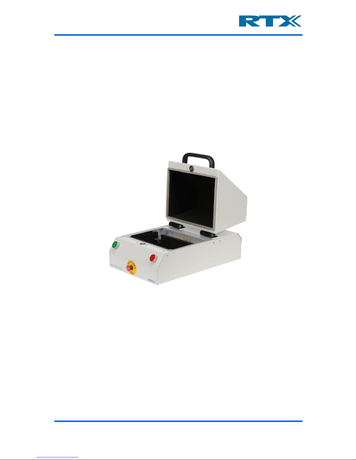
The RTX2300 Smart ATE is a highly optimized automated test solution for calibration and
functional test in the production of wireless devices (including DECT, GSM, Wi-Fi, Bluetooth™, etc.). The design of the RTX2300 is based on extensive experience within development and installation of Automated Test Equipment (ATE) systems, and hence, key
parameters as handling-time, flexibility and size have been considered as part of the design
process.
The RTX2300 Smart ATE is a multipur pose solution to simplify and cost-reduce the production test environment dramatically compared to traditional “rack and stack” wireless
test implementations. The RTX2300 reduces the complexity and size of the ATE system
through the inclusion of mo dular instrumentation internal to the test unit, including a digital
volt meter, tone generator, and signal multiplexer. Optional internal instrumentation
includes a programmable power supply, and a frequency counter. These components allow
for the calibration and test of the baseband and audio portions of a Device Under Test
(DUT) without the need for additional external equipment.
The flexible nature of the RTX2300 Smart ATE enables a swift physical reconfiguration and
it can streamline th e manufacturing process, since in literally a matter of seconds, it can
be physically reconfigured to accommodate different products and test types. The RF
shielded compartment of the RTX2300 can be customized with a device-specific probe
fixture, including a pneumatic capture unit to automatically hold the DUT in place during
test. Furthermore, the RTX2300 can decrease overall product test time since it has been
designed to allow several units to be set up in parallel, enabling optimal use of RF, baseband, acoustic test resource, and effectively reducing the handling time of the DUTs.
The RTX2300 Smart ATE can be used for Printed Circuit Board (PCB) as well as final product
testing. It features a customization area that enables the interco nnection betwee n internal
and external measurement functionality and the DUT, hence reducing both space
requirements and complexity for the total test system. The flexibility of the RTX2300
simplifies the customization of the test platform, and enables economical replication. A
production test system can be implemented by using one or more RTX2300 Smart ATE
units in combination with an RF communication test e r (s uch a s the RTX2011/RTX2012 HS
DECT/DECT 6.0/CAT-iq RF Tester or Agilent 8960) and a PC for executing the test application.
Page 12

User’s Manual V1.00 RTX2300 – Smart ATE 12
B. Unpacking the RTX2300 Smart ATE
i. Initial Inspection
Please inspect the shipping container for damage. If the shipping container or packaging
material is damaged, it should be kept until the contents have been checked mechanically
and electrically. If any mechanical or electrical damage is observed, please no tify RTX A/S.
Please refer to the description on how to contact RTX A/S provided in this document. Please
also keep the damaged shipping materials (if any) for inspection by t he carrier a nd an RTX
A/S representative.
NOTE: The handle on the shield must not be used for lifting the RTX2300 out of the box.
ii. Box content
When unpacking the RTX2300 Smart ATE please verify that the items listed below are
included in the box:
• RTX2300 Smart ATE unit
• Power Supply
• USB cable (for communication b etween the RTX2300 unit and a PC)
• Optional items (modules, fixtures, QSK kit etc.) – if ordered
C. General overview of the RTX2300 Smart ATE Unit
The RTX2300 Smart ATE unit provides a wide range of external as well as internal connectors. The connectors and functions can be divided into the following categories:
• Rear panel Connectors
• Internal Connectors
o Shielded Fixture Bay Connectors
o Controller Chamber Connectors
• Front Panel Functions
Each of these categories will be descibed in more detail in the following.
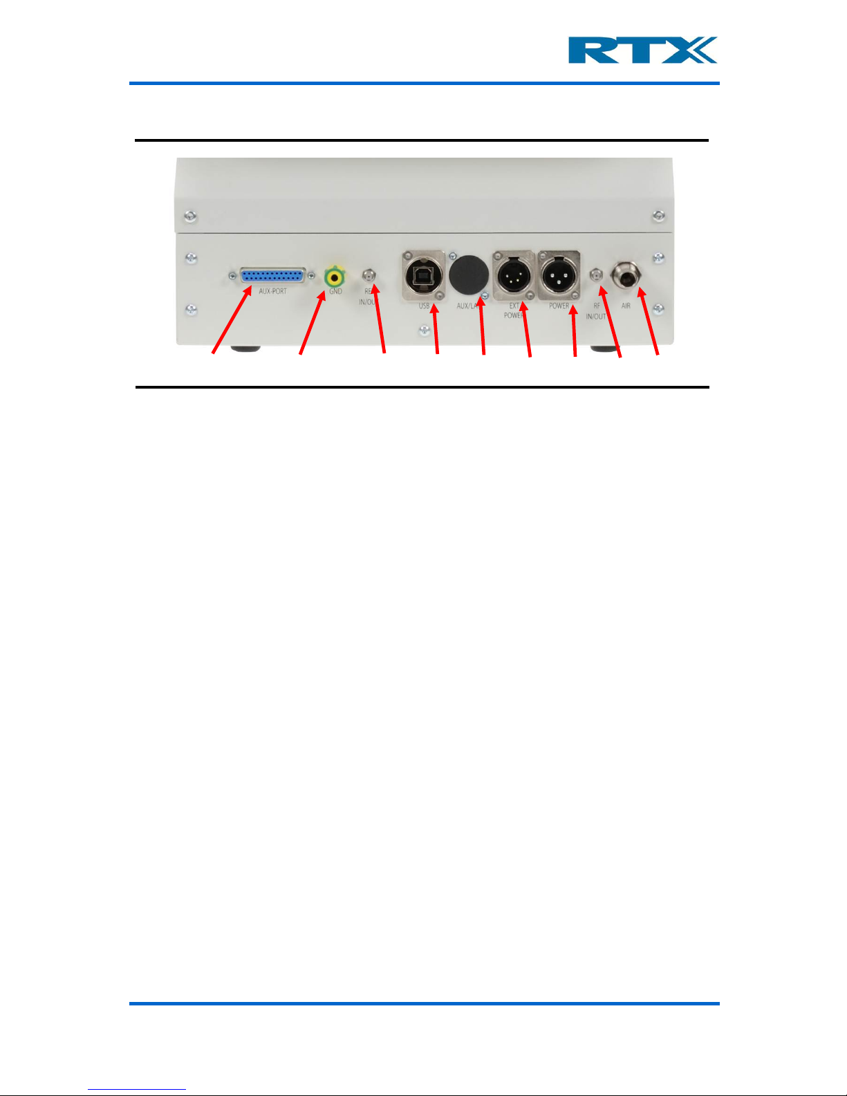
i. Rear Panel Connectors
The RTX2300 Smart ATE provides rear panel inputs/outputs for many functions. Below a
brief overview of the available connectors is provided alon g with a description of each of
the connectors.
Page 13
User’s Manual V1.00 RTX2300 – Smart ATE 13
Available rear panel
• AUX Port (): Connector (type 25-pin DSUB female) for external acquisition unit
measurement channels (e.g. Agilent 34970A or similar). For a detailed pin
description please refer to section
v on page 112. Th e AUX Port can be used for
connecting external measurement equipment to the DUT, and it provides the following internal routing:
o 10 voltage measurement channels (20 wires) are routed to the Customized
Connector Block (CCB) selection matrix (for more information regarding the
CCB block please see chapter 5)
o One channel (2-wire) for current measurement is routed directly to the
Standard Connector Block (SCB) matrix (for more information regarding the
SCB block please see chapter 5)
o One channel from the internal AD converter can be routed to the acquisition
unit
• Ground connector (): This ground connector is used for connecting all instrumentation together to avoid ESD problems.
• CLK Port (): Connector (type SMA female) for connecting to external equipment.
The port has the following functions:
o DUT CLK output to external frequency counter (e.g. Agilent 53181A)
o 10MHz reference in (a reference signal from an extern al source is used as
reference for the optional internal frequency counter to measure the DUT
Clock)
o 10MHz reference out (a source signal from the optional internal frequency
counter and to external equipment)
• USB Interface (): This interface should be used together with a Windows®
based PC to control the test set and to query data from the test set. The USB
interface on the RTX2300 unit is a Type B receptacle, and hence, a standard USB
cable with Type A-B plugs can be used to connect the RTX2300 unit to a PC. Please
note that the external USB connector is internally connected to a 7-port USB HUB
to provide both USB connection and a serial connection. Furthermore, 4 of these
ports are available as USB ports for the 4 expansion slots. The USB ports support
USB 1.1.
• LAN/PSTN () (optional): This connector (RJ45 type) is optional and is a connector for Ethernet testing options. Furthermore, this connector can also be used
for PSTN/FXO/FXS testing options.
Page 14

User’s Manual V1.00 RTX2300 – Smart ATE 14
• DUT Ext. Power supply (): Connector (type is XLR-4 male) for the external
power supply of the DUT and should provide V+, V-, V+ s ense and V- sense. Please
note that double pins for V+ and GND must be used.
• Fixture power supply connections (): Connector (type XLR-3 male) for the
fixture power supply (+12V, 5A) – i.e. the main positive supply for the RTX2300
unit.
• RF IN/OUT (): Connector (type SMA female) for the RF interface to the DUT. In
the standard configuration the RF is routed directly to the SCB block to enable
measurements of one antenna. If measurements of more antennas are need ed an
RF Switch Module (opti on) ca n be install ed in the RTX2300, hence pro viding acce ss
to more than one antenna at the SCB/CCB block through the RF IN/OUT connector
on the rear panel. When connecting the SMA male connector at the RF IN/OUT
connector it must be mounted with a maximum torque of 1.4 Nm.
• Air connector (): Connection for air supply for the pneumatic activators in the
RTX2300 Smart ATE.
ii. Internal Connectors
The RTX2300 is divided into two chambers:
• Shielded Fixture Bay Chamber – connector s in the internal shiel ded chamber are
used for connecting the fixture to the RTX2300.
• Controller Chamber – connectors in the main controller chamber are used for
connecting optional modules and customizing the internal routing of signals.
The connectors in each of the chambers are briefly described in the following.
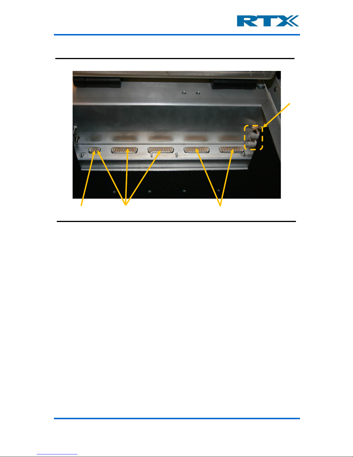
Shielded Fixture Bay Connectors
The fixture bay is prepared with interfaces to the Smart ATE functionalities and external
RF equipment. The signal lines are filtered and ca n be accessed ei ther at the co nnectors in
the bottom part of the fixture bay (standard interface in the basic unit) or the optional
Quick-Swap Kit (QSK) connectors. Consequently, the se connectors are used for connecting
the fixture to the sig nal l ines . In th e fi gures bel ow the fixt ure b ay connectors are shown in
both the basic configuration and with a QSK (fixture bay part) installed.
Page 15
User’s Manual V1.00 RTX2300 – Smart ATE 15
Available Fixture Bay Connectors (basic configuration)
• Power supply for DUT (): In the basic RTX2300 configuration the power supply
connectors for the DUT are in the 9-pin male DSUB connector. With a Quick-Swap
Kit installed the power supply for the DUT is accessible through two connectors Type
M-Flat female connectors (GND and Power).
Page 16
User’s Manual V1.00 RTX2300 – Smart ATE 16
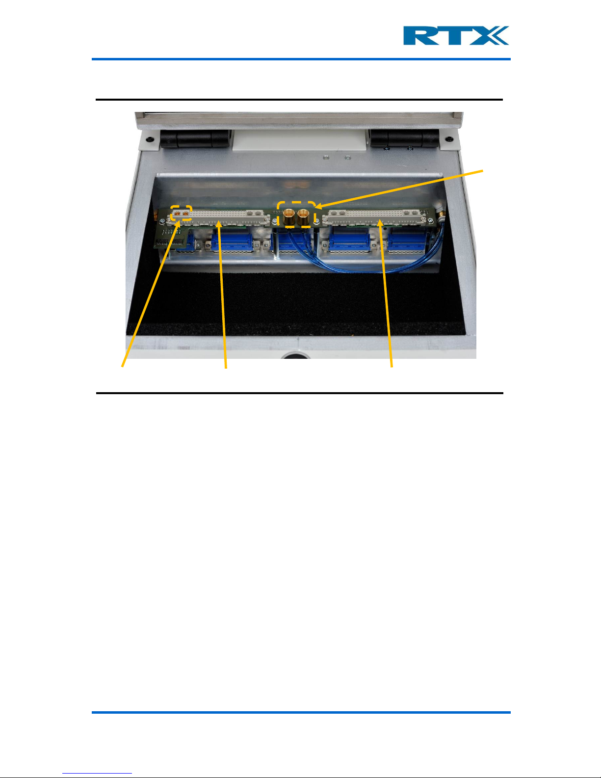
Available Fixture Bay Connectors (with fixture bay Quick-Swap Kit installed)
• Standard Connection Block (SCB) (): The SCB is used for general purpose
connections to the test-interface. In the basic configuration the SCB signals are
distributed over the 9-pin male DSUB and two 25-pin male DSUB’s. With a QSK
installed the SCB connector is a 60 + 4 Type M female. Please note that the power
supply for the DUT is available from this connector (as mentioned above).
• Pneumatic connectors (): Connectors f or pneumatic control of fixture. In the
basic RTX2300 configuration the pneumatic connectors are placed to the right on
the bay wall. With a QSK installed the pneumatic connectors are placed on the QSK
PCB for easy access.
• Customization Connection Block (CCB) (): The CCB is used for user configu-
rable connections to the test-interface. In the basic configuration the CCB signals
are distributed over two 25-pin male DSUB’s. With a QSK in stalled the CCB connector is a 60 + 4 Type M female.
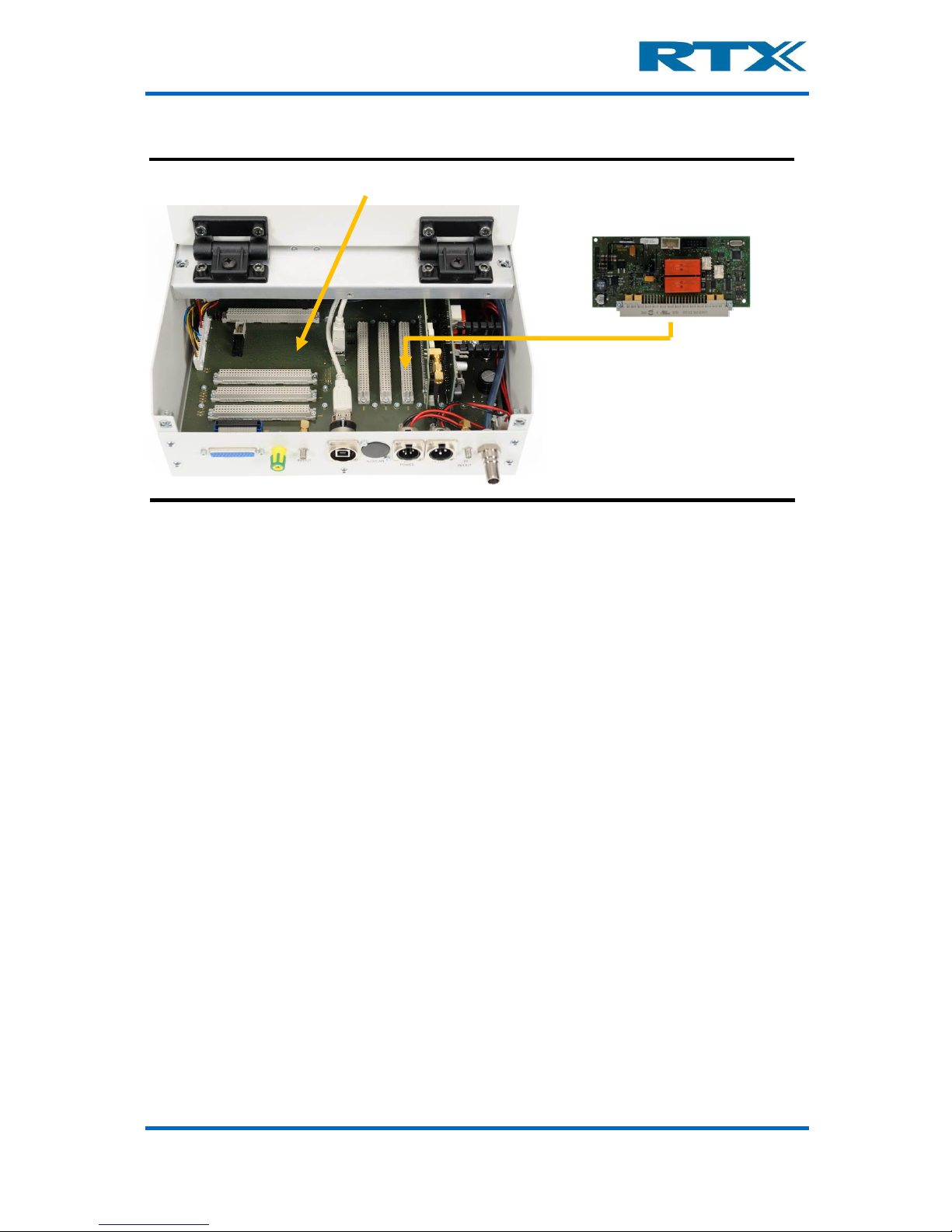
Controller Chamber Connectors
The controller chamber can be accessed by removing the back cover (please see section 0
on page 24 for details on how to remove the back cover). In the controller chamber of the
RTX2300 main board provides two main categories of connectors – connectors for modules
and connectors for customization boards (input and output) . Please note that two optional
module cards have been inst alled in the figure below – i.e. they are not part of a basic
RTX2300 configuration.
Page 17
User’s Manual V1.00 RTX2300 – Smart ATE 17
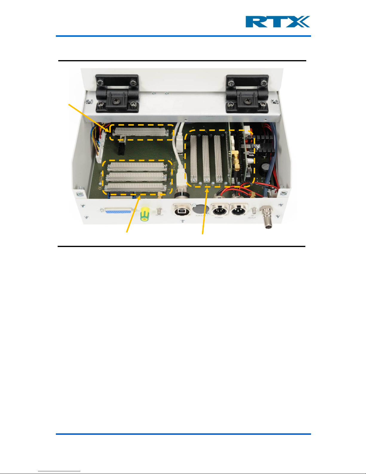
Controller Chamber Connectors (with two optional modules installed)
• Customization connector (output) (): This connector (2 x 32 pins female) is
used for the customization board for output signals (i.e. customization of the CCB
functionality).
• Customization connectors (input) (): In all three customization input con-
nectors (2 x 32 pins female) are available. The connector closest t o the rear panel
is also connected to the external AUX-port.
• Extension Module connectors (): In total there are five connectors (4 pcs. 2 x
32 pins female and 1 pcs. 60 + 4 pins female) avai lable for (optional) extension
modules. Please no te that the basic RTX2300 Smart ATE is not equ ipped with any
extension modules.
Please note that the customization connectors also are referred to as the option matrix
while the extension connectors are referred to as the instrumentation area.
iii. Front Panel Functions
The front panel on the RTX2300 Smart ATE provides many buttons for controlling the unit
(e.g. start/stop of the test sequence) – each of these are briefly described below. Please
note that the RTX2300 can be delivered both with (standard) or without (optional) the
shielded lid.
Page 18
User’s Manual V1.00 RTX2300 – Smart ATE 18
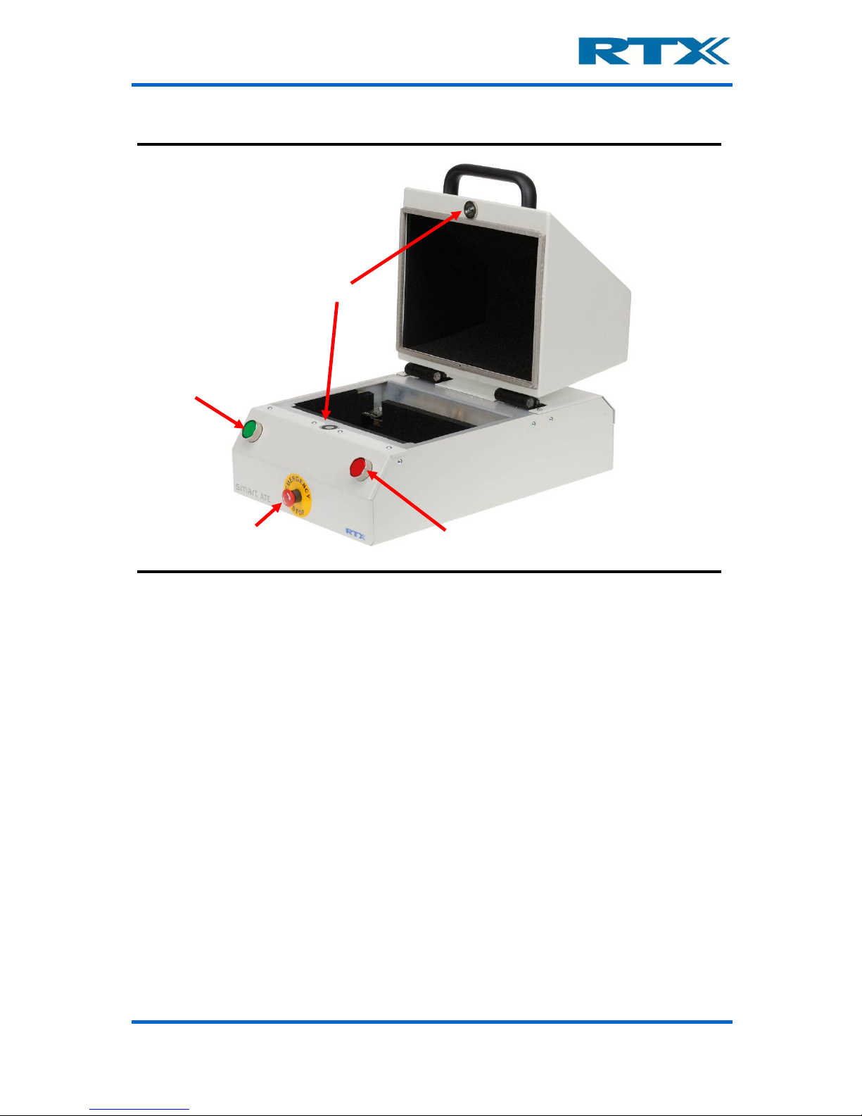
Front panel functions
• Emergency stop (): The emergency button is a safety precaution. When pressed
all power to the RTX2300 is cut and all pneumatic valves controlled by the RTX2300
are released to disconnect the DUT.
• Push buttons / indicators ( & ): The two push buttons are intended to be
used as Start/Stop buttons. However, the button functionality can be customized
through the SW API. F urthermo re, ea ch of the buttons c an be c onfigure d as nor mal
input or as interrupt inputs with a programmable de-bounce time. The indicators in
the buttons can be used for showing the status of a test sequence (i.e. PASS /
FAIL). They are controlled from the SW API, and hence, the functionality of the
indicators can be customized as well.
• Top-lid closing mechanism (): The top-lid closin g mechanism is a magnetic
“lock” connected to an electrical motor which will pull down the lid. In the standard
configuration the test sequence is started when clo sing the lid and upon com pletion
of the test sequence the electrical motor will lift the lid. One signal for controlling
this mechanism is available from the SW API.
Page 19
User’s Manual V1.00 RTX2300 – Smart ATE 19
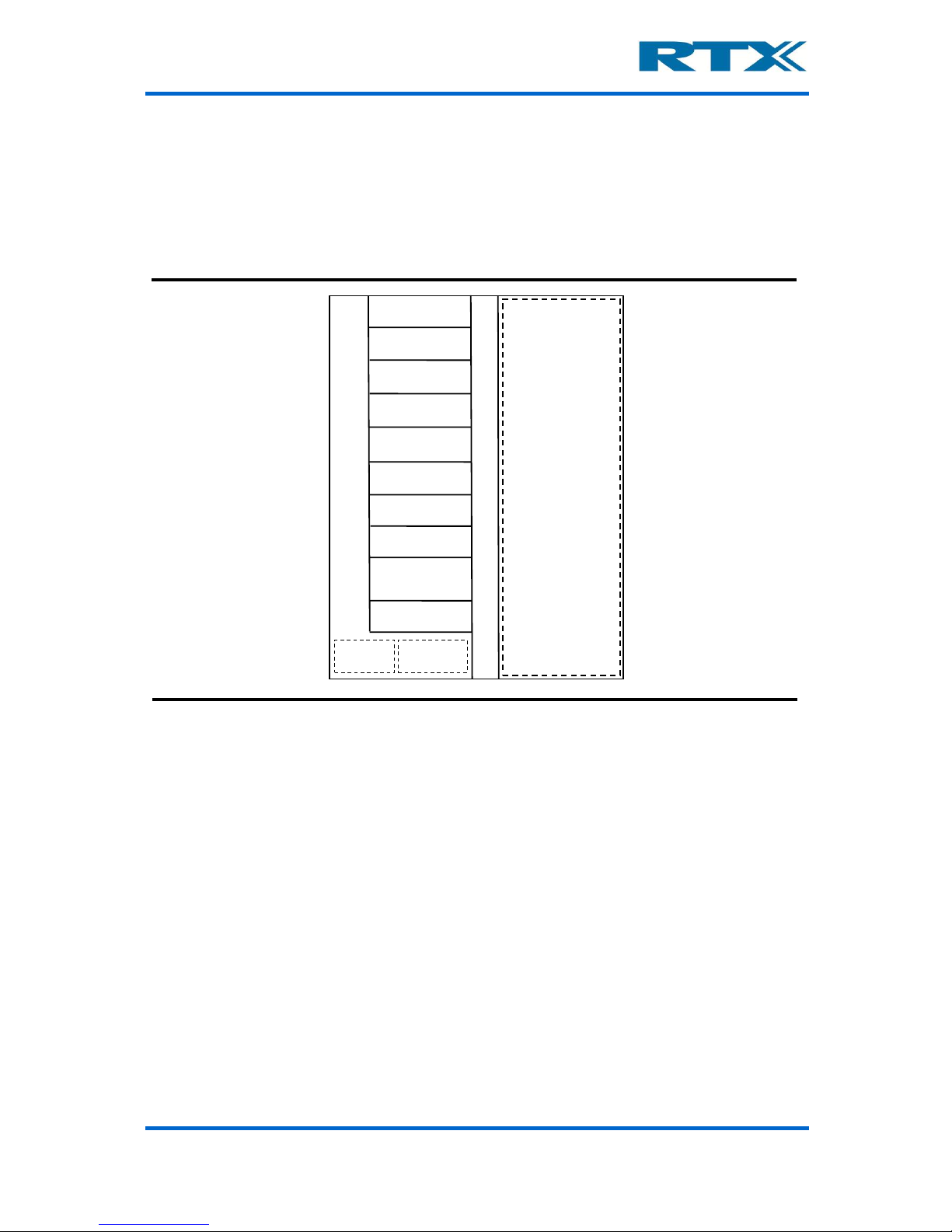
D. Overview of instrumentation and functional blocks
The figure below provides an overview of the instrumenta tion in the standard confi guration,
main functional blocks of the RTX2300 and the available o ptional modules.
Overview of RTX2300 main functional blocks and instrumentation
Shielded Fixture Area
Customization Area
Controller
DVM
Tone generator
Signal multiplexer
GPIO
Option:
Progammable PSU
Option:
Frequency Counter
Option:
RF Switch
Option:
Battery simulator
New options /
customer modules
Fixture and
box control
RTX2300
Power supply
Connectivity Option:
UUT communication
interface (I2C/SPI)
The RTX2300 is a very flexible and well-equipped platform which includes the following
instrumentation in the standard configuration:
• Digital AC & DC Voltmeter (DVM)
• Tone generator
• Sign a l m ultiplexer
• GPIO
In addition to the standard instrumentation the RTX2300 Smart ATE also supports installation of optional modules and features like:
• Programmable Power Supply Unit (PSU)
• Frequency counter
• RF switch
• DUT communication interface (I2C / SPI)
• New opt ions / cu sto mer modules
The instrumentation will be outlined in more detail in the following sections including an
overview of the main functional b lock s. For more information on the optional modules and
features listed above please refer to chapter 4 (especially section A on page 81).
Page 20
User’s Manual V1.00 RTX2300 – Smart ATE 20
i. Digital AC & DC Voltmeter (DVM)
The DVM is divided into two parts – an AC part and a DC part. The DC part is an 8-channel
digital voltmeter with an operational range from -10V to 10V in 10mV steps. It can operate
in two modes (static / differential) and it supports a wide range of scale configurations.
The AC par t is a 2-channel digital voltmeter. It can operate in static or differential mode
and it can be configured to measure RMS or peak value. A built-in attenuator enables
attenuation of the input signals and distortion measurements are also supported. Please
refer to the formula for THD outlined in section v on page 131.
ii. Tone Generator
The RTX 2300 has tree signal generators – one with high-level output and two with lowlevel outputs. The two low-level outputs can be confi gured to operate in differential mode.
The level, frequency an d confi guratio n of the g enerators can be changed from the SW API.
iii. Signal multiplexer
The RTX2300 Basic unit has 8 relays for signal switching. They are all available through
the option matrix (i.e. the customization connectors) and can be routed to the CCB connectors. Each relay has two sets of contacts.
In addition to the relays there are 16 connections to the expansion slots. These connections
can be used to route signals from the option-board in the expansion slot to the test bed
via the option matrix.
iv. GPIO
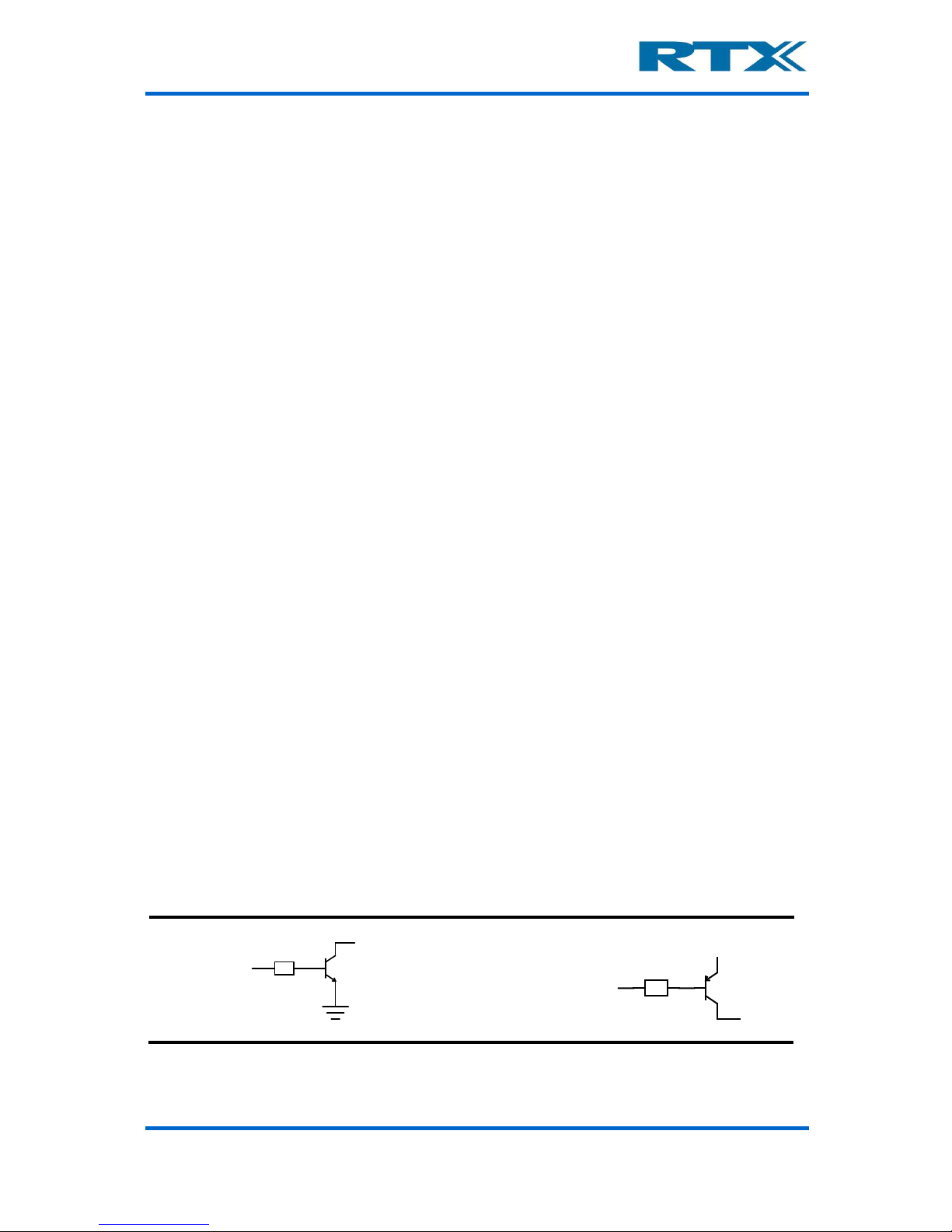
The RTX2300 Smart ATE has 16 digital output ports (8 sink outputs an 8 source outputs)
and 8 digital input ports. The port state of all ports can be controlled and read from the
SW API. The 8 digital inputs are 5V TTL logic and the sink and source outputs are as
outlined below.
Simplified sink (left) and source (right) output schematic
Vref
Page 21
User’s Manual V1.00 RTX2300 – Smart ATE 21
In addition to the digital input and output ports the RTX2300 also includes two DACs.
Please note that these DACs are only intended for DC values (i.e. they do not support audio
signalling).
v. Main functional blocks in the RTX2300
From a functional perspective the functionality of the RTX2300 Smart ATE can be divided
into the following categories:
• Fixture and box control
• Power supply
• Communication interfaces
Each of these categories will be outlined in more detail in the followin g.
Fixture and box control
To control the fixture fu nctionality the following signals are av a ilable:
• 4 sense signals (e.g. for detecting fixture position)
• 4 control signals (e.g. for motor or relay control)
• 1 signal for controlling the lid closing mechanism
• Signals for controlling the pneumatic slide is available through a pin header
connector
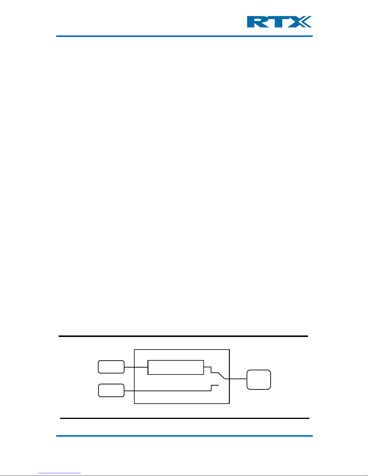
Power supply
The main power supply for the RTX2300 Smart ATE unit is a 12V external switch-mode
adaptor connected to the power-plug. This adaptor supplies all the internal circuitry
including the installe d modules. By adding an optional Programmable PSU module to the
RTX2300 unit the DUT can also be powered through the RTX2300. A more detailed
description of this optional module is given on page 82. An alternative way to supply the
DUT with power is to connect an external power supply to the DUT Ext. Power connector
on the rear panel of the RTX2300 (see figure below). The power supply to use for the DUT
can be controlled from the SW API.
Power supply switching for DUT
RTX2300 Smart ATE unit
Power
Adaptor
UUT Ext.
Power
Programmable PSU
Module (option)
UUT
Page 22

User’s Manual V1.00 RTX2300 – Smart ATE 22
Communication interfaces
The RTX2300 Smart ATE is equipped with one USB connector which serves as the only
communication interface between the PC with th e test applicat ion and the RTX2300 unit.
Inside the RTX2300 the USB connection is split into 7 USB ports through in an internal full
speed USB Hub. Furthermore, a serial communication port is available for DUT communication – i.e. the following communication interfaces are supported at the DUT:
• Four USB ports are available for the expans ion-slots (i.e. one for each slot)
• One USB port is converted to a UART for communication channel to the RTX2300
main board CPU
• One USB port is used as communication channel to the CCB
• One USB port is used as communication channel to the DUT (i.e. from the PC with
the test program directly to the DUT) through the SCB
Expansion slot USB interfaces
Each expansion slot (except the PSU module slot) is configured with a separate USB
connection, and hence, these are used for communicating with the installed modules.
RTX2300 control interface
This interface is used for communication to control the functions in the RTX2300 unit.
CCB USB interface
This interface is a general-purpose USB connection and it is connected directly to the CCB
interface.
SCB USB interface
This interface is a general-purpose USB connection and it is connected directly to the SCB
interface.
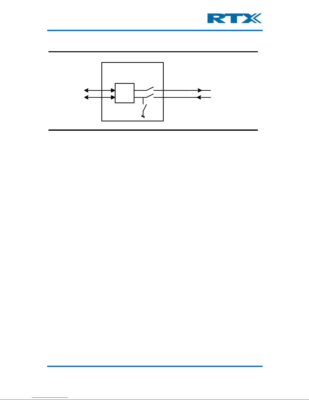
DUT serial communication configuration
To communicate with the DUT the RTX2300 has an UART for serial communication. Seen
from the PC the UART is a USB com-port. The UART is implemented as outlined below and
it has automatic level detection.
Page 23
User’s Manual V1.00 RTX2300 – Smart ATE 23
Simplified DUT UART Port
As indicated in the figure above the UART has tree modes (can be controlled from SW):
• Disabled - In Disabled mode the UART is disconnected from the DUT. This is the
default mode after power up of the RTX2300.
• Normal - In Normal mode th e UART is connected to the DUT and ready for communication.
• Boot-mode - In boot-mode the RX-line is connected to ground-level to bring th e
DUT in boot-mode (RTX equipment). When the DUT is in boot-mode the UART must
be set to “Normal” before communication can be established.
RTX2300 Smart ATE unit
PC
USB
to
UART
Boot-mode
Enable
UART interface
DUT
USB interface
Page 24
User’s Manual V1.00 RTX2300 – Smart ATE 24
E. Installing RTX2300 Options
As mentioned before, optional components for the RTX2300 are available – these can be
categorized into four different categories:
• Modules
• Quick-Swap Kit
• Fixture Kits
• Connectivity options
Installation of the firs t three categories will be outlined in more detail in the following.
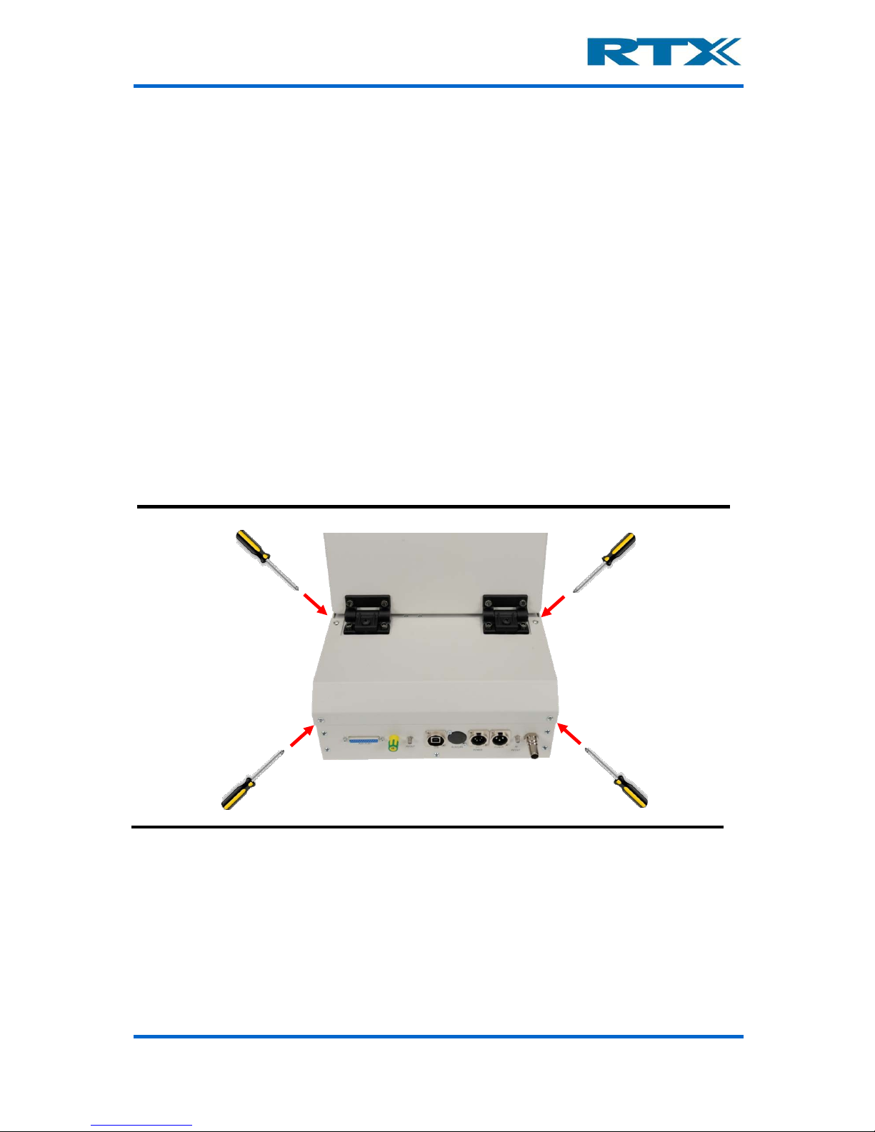
i. Installing modules
The modules are installed in the controller chamber, and hence, the lid to the controller
chamber must be removed (see figure below). Please use a screwdriver to remove the four
screws holding the lid.
Removing the four screws holding the controller chamber lid
After removing the lid, the controller chamber is now accessible and the extra module(s)
can be installed in the empty extension slots (see figure below). Please be aware that the
right most connector is different from the other four connectors. This connector is reserved
for the programmable PSU module. Please make sure to install the module correctly in the
connector – i .e. with t he front s ide of t he modul e (i.e. the top-side of the PCB with all main
components mounted) pointing to the right. To ensure correct operation of the module
please also make sure to press the module tightly into the connector on the controller
board.
Page 25
User’s Manual V1.00 RTX2300 – Smart ATE 25
Controller chamber - installing a module in an empty extension module slot
After installing the module(s) please put the controller chamber lid back on again and
tighten the four screws holding the lid. To use the modules from the test program a SW
package installation might be necessary. For more details on this issue please refer to the
specific module descriptions in chapter 4.
ii. Installing Quick-Swap Kit
The Quick-Swap Kit (QSK) is divided into two parts – a fixture bay part and a fixture part.
Installation of each of these parts will be outlined in the following.
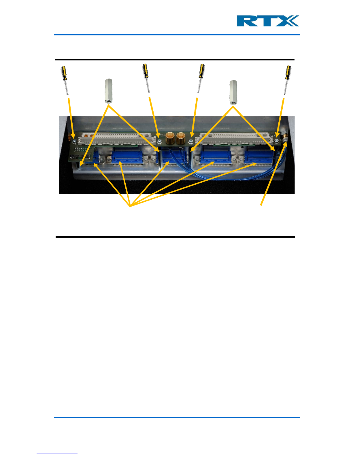
Installing the fixture bay part of the Quick-Swap Kit
The first step is to remove the fixture part (if installed) to gain access to the fixture bay.
Place the QSK in the fixture bay close to the standard DSUB (male) connectors in the
fixture bay and connect the DSUB connectors on the QSK to the standard connectors in
the fixture bay. Please ensure tha t the connectors are connected correctly.
Next step is to connect the two p neuma tic conn ec tors o n t he QSK to th e con necto r s in the
fixture bay. When all connectors have been connected please mount the four spacers
(included in the QSK fixture bay part package) in the fixtur e bay a nd p lace the QSK o n top
of the spacers. Please ensure that the spacers are tightened. Mount and tighten the four
screws (also included in the QSK fixture bay part package) to fasten the QSK on top of the
spacers.
Extension module
(front side)
Put module into empty slot with
front side pointing to the right
Controller board
Page 26
User’s Manual V1.00 RTX2300 – Smart ATE 26
Installing the Quick-Swap Kit (fixture bay part)
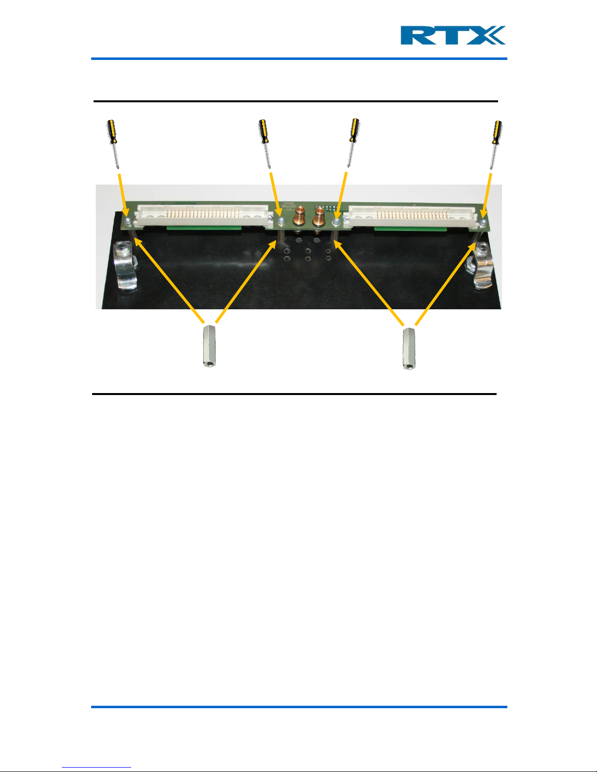
Installing the fixture part of the Quick-Swap Kit
To enable easy installation of the fixture part QSK a new fixture plate should be used (i.e.
without any connectors or other equipment installed). However, the installation steps
outlined below should apply to all fixtures, but it could be necessary to remove some of
the items installed on th e fixture.
The first step is to mount the QSK spacers (included in the QSK fixture part package) on
the fixture. Place the QSK on top of the spacers. Mount and tighten the four screws as
shown in the figure below.
Please note that only the SCB connector, CCB connector and one of the connectors on the
top side of the QSK are mounted, and hence, connecting the QSK interface to the fixture
pins must also be done. This is, however, outside the scope of this section but for more
information on customizing the fixture please refer to chapter 6 (especially section D on
page 115).
Connect the female DSUB connectors
on the QSK to the DSUB connectors
on the controller board
Connect the pneumatic connectors
on the QSK to the pneumatic
connectors in the fixture bay
QSK spacers
QSK spacers
Page 27
User’s Manual V1.00 RTX2300 – Smart ATE 27
Installing the Quick-Swap Kit (fixture part)
QSK spacers
QSK spacers
Page 28
User’s Manual V1.00 RTX2300 – Smart ATE 28
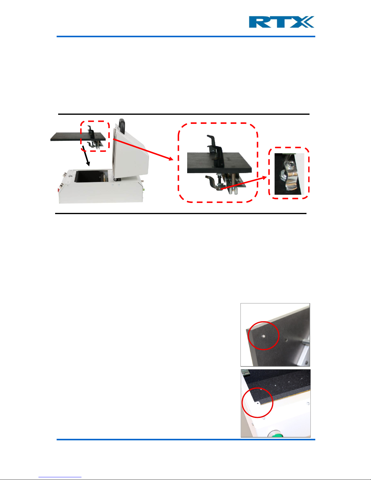
iii. Installing a fixture kit
The first step is to remove the fixture part (if installed), hence unlocking the two locks on
each side of the fixture and removing it fro m the RTX2300 unit. The next step is to prepare
the new fixture and mount it in the fixture bay.
Installing a fixture kit in the RTX2300 Smart ATE unit
The installation process defers slightly depending on whether or not a QSK has been
installed:
With QSK installed:
If a QSK has been installed the installation process i s quite straightforward. Just make sur e
the (pneumatic, CCB and SCB) connectors on the fi x tur e QSK part are connected p r o perly
to the fixture bay part QSK connectors and secure the fixture by locking the two fixture
locks.
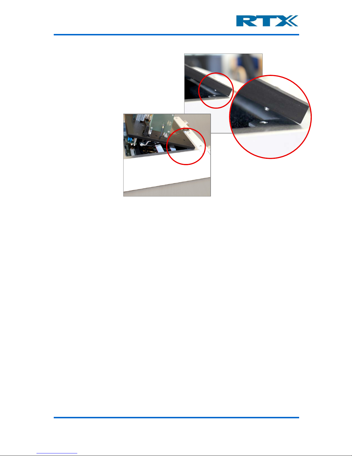
It is recommended that following steps are followed to mount the fixture insert into the
fixture bay of the RTX2300 unit.
1) The fixture must have a guide-pin (see picture 1)
mounted at each corner opposite to the quick-swapconnectors of the fixture insert.
2) In the fixture bay are there two guide-holes (see picture 2) in which the guide-
pins in which the guide-pins must fit.
Picture 1
Picture 2
Page 29
User’s Manual V1.00 RTX2300 – Smart ATE 29
3) The mounting of the fixture insert in
the fixture bay must begin with an
alignment of the guide-pins with the
guide-holes (see picture 3).
When the guide-pins and holes are
aligned the connectors can be pressed
in place (see picture 4)
Without QSK installed:
To connect a fixture without a QSK installed the connectors on the fixture must be
connected directly to the standard interface in the fixture bay. If the fixture includes a
pneumatic slide the pneumatic tubes must be connected to the pneumatic connectors on
the back panel of the fi xture bay (see the figure on page 14 for an overview of the standard
fixture bay connectors). The next step is to connect the fixture SCB and CCB connectors
to the connectors in the bottom of the fixture bay. Please make sure to connect the fixture
correctly and secure the fixture by locking the two fixture locks.
Picture 4
Picture 3
Page 30
User’s Manual V1.00 RTX2300 – Smart ATE 30
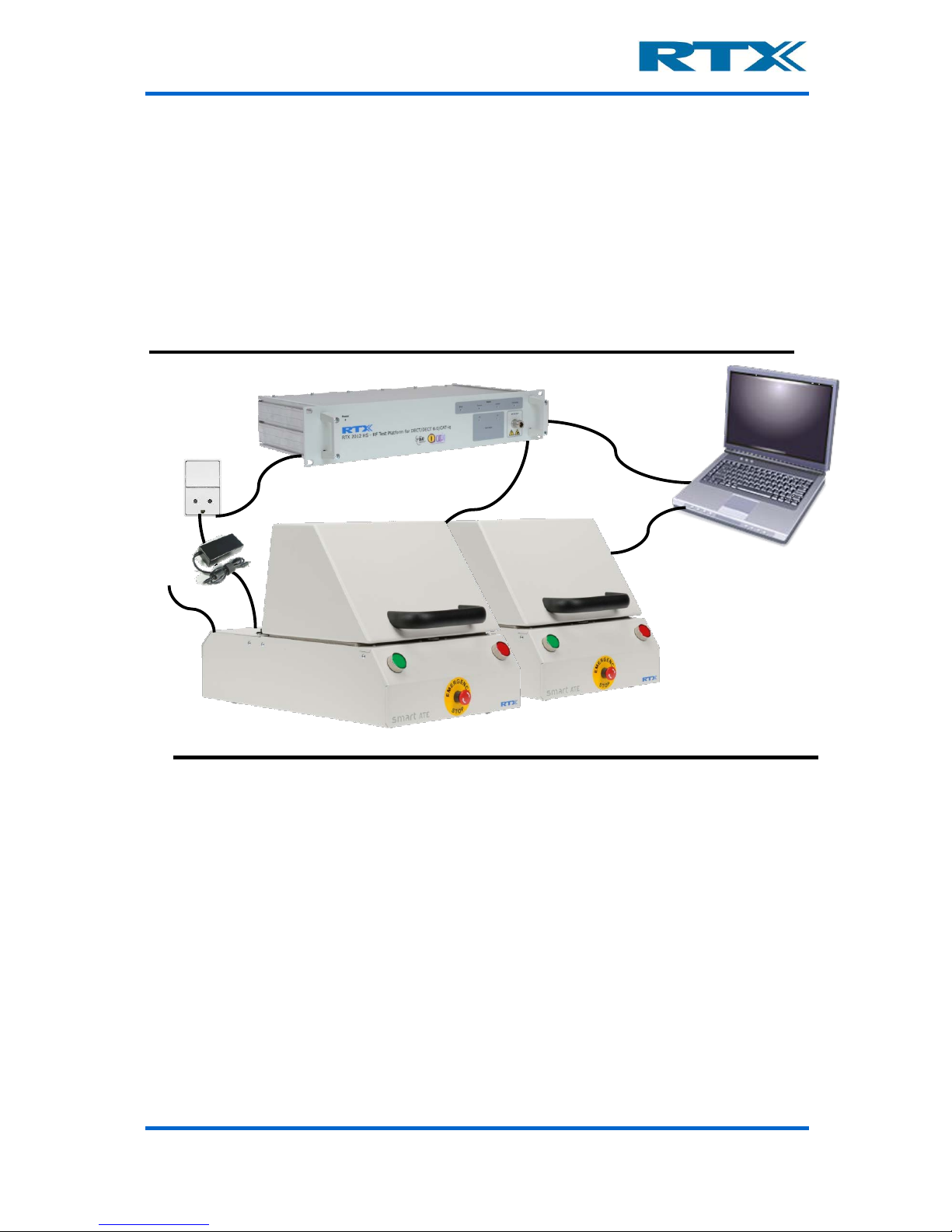
F. System setup and installation of the RTX2300
The RTX2300 is the key component in an automatic test system setup an d it deliverers
most of the instrumentation (PSU, DVM, relays etc) needed to configure a production test
setup for a large variety of applications. Th e only external parts required are a Windows
based PC and an RF communication tester (if RF testing is required). Hence, a typical setup
could look like the one outlined in the figure below. It consists of a Windows based PC, an
RTX2012 RF tester (in case of a DECT product) and two RTX2300 Smart ATE uni ts. Please
note that one PC can control more than one RTX2300 unit (as indicated in the figure).
Simple automatic production test setup with RTX2300 and RTX2012
i. Connecting the RTX2300 Smart ATE
To configure a simple production test system (as the one outlined above) please follow the
four steps below to setup the above RTX2300 Smart ATE system.
1. Connect the RTX2300 units to the PC – the first step is to connect the RTX2300
units to a PC using the provided USB cables. In the example above both units are
connected to the same PC.
2. Connect external equipment to the RTX2300 units – if external equipment
is required (for example an RF tester) this must be connected to the relevant connectors on the rear panel. In the setup above an RTX2012 RF tester has been
connected to the two RTX2300 units (through the RF port on the rear panel).
3. Connect air for the pneumatic controls in the RTX2300 units – to enable
the pneumatic functionality inside the RTX2300 air must be connected to the air
connector on the rear panel of the RTX2300 units.
<RF signal>
Windows© based PC
RTX2012 RF tester
<USB Control>
<USB Control>
Mains power
Air RTX2300 Smart ATE units
Page 31

User’s Manual V1.00 RTX2300 – Smart ATE 31
4. Connect power to the RTX2300 units – the last step i s to connect the RTX2300
to the mains power using the supplied adaptors. Before switching on power to the
RTX2300 units please ensure that the emergency button is released on both units.
If this is the first time the RTX2300 units have been connected to the PC installation
of the RTX2300 driver package will be initiated (i.e. the PC will as k for driver se tup
when switching on power to the equipment). Please follow the instructions in
section G on page 31 (below) for installing the necessary drivers.
In addition to the above steps please also make sure to connect the RTX2300 to a proper
ground level to avoid problems with ESD.
G. Installing the PC Software
In this section the installation process of the supplied SW is outlined. However, before
installing the SW (which can be downloaded from the RTX Tester Download Center at
www.rtx.dk/testers/downloadcenter
) please c onfirm that the PC o n which t o install the SW
adheres to the minimum requirements outlined below. If it does not, then successful
operation of the RTX2300 Windows applications cannot be guaranteed.
System Part
Minimum requirement
CPU
1 GHz processor (Intel© or AMD) or faster
RAM
1 GB (2 GB for 64-bit operation)
Available disc space
75 MB
Monitor resolution
1280 x 1024 pixels or higher
CD-ROM drive
YES
Ports
Available USB port
Operating System
Windows XP/Windows 7 (32- or 64-bit)
The RTX2300 SW package includes the necessary drivers, supporting Windows
applications, RTX2300 DLL, source code for demo applications, and interface
documentation. The source code for demo applications and the interface documentation
will be described in more detail in chapter 7. The following drivers and supporting Windows
applications are included:
• RTX2300 DUT UART Driver
• RTX2300 Basic Unit Communication Interfac e Driver
• RTX EAI Port Server
• RTX2300 Detective debug application
• RTX2300 DLL
• RTX2300 USB Bridge Driver
• RTX2300 .net
In the following instructions for installing the above items are out lined. Please note that
the instructions provided here outlines installation of SW for the basic RTX2300 unit.
Consequently, if extension modules have been installed in the RTX2300 please refer to
section A in chapter 4 for information on how to install specific module rela ted SW packages
(if relevant). However, one exception is the driver for the Programmable PSU; this driver
is included in the RTX230 0 Basic Un it Commun ication Interface, since it is tight ly couple d
to the operation and interfaces of the RTX2300 main board. Furthermore, the RTX2300
Detective application also provides specific PSU functions.
Page 32

User’s Manual V1.00 RTX2300 – Smart ATE 32
The typical installation proced ure is ou tlined below and will be describ ed in more det ail in
the next sections:
1. Install the RTX2300 Basic Unit SW package: The first step in a typical RTX2300
installation process is to install the RTX2300 Basic Unit SW package. This package
will also install the RTX2300 DLL and the RTX2300 Detective debug application
along with extract driver files and documentation. Hence, this should be done before
switching on the RTX2300 uni t for the first time. Please note that both the RTX2300
USB Bridge Driver and the RTX EAI Port Server can be installed as part of the
installation process.
2. Install the RTX2300 USB Bridge Driver: Install the RTX 2300 USB Bridge Driver
to be able to communicate with the RTX2300 unit over the USB interface. The driver
installation can be initiated as part of the RTX2300 Basic Unit SW package or started
manually.
3. Install the RTX EAI Port Server: Install the RTX EAI Port Server to be able to
map the COM-ports made available by the RTX2300 DUT UART Driver and the
RTX2300 Basic Unit Communication Interface Driver. The driver installation can be
initiated as part of the RTX2300 Basic Unit SW package or started manually.
4. Install the RTX2300 DUT UA RT Driver: Install the RTX2300 DUT UART Driver to
enable communication direc tly wit h the DUT. Normally this driver is installed upon
switching on the RTX2300 unit for the first time.
5. Install the RTX2300 Basic Unit Communication Interface Driver: Install the
RTX2300 Basic Unit Communication Driver to enable communication with the
RTX2300 unit (i.e. this is the driver for controlling the RTX23 00 unit). N ormally thi s
driver is installed upon switching on the RTX2300 unit for the first time.
Page 33

User’s Manual V1.00 RTX2300 – Smart ATE 33
i. Installing the RTX2300 Basic Unit SW
Turn on the PC and download the RTX2300 SW package from the RTX Download Center
(http://www.rtx.dk/testers/downloadcenter
) and save the file on the PC. Please note that
the outlined screenshots and the procedure described in this paragraph are based on a
PC using Windows XP. Hence, if you use another Windows OS on your PC the setup
procedure can deviate a bit from the one shown here. As noted above the RTX2300 DLL
and RTX2300 Detective debug application will be installed as part of the RTX2300 Basic
Unit SW package installation process.
Select and unzip the downloaded RTX2300 SW package.
Click on the Setup_Rtx2300System.exe file.
Page 34

User’s Manual V1.00 RTX2300 – Smart ATE 34
Click Next to continue the installation process
Enter the destination location in which to install the RTX2300 Basic Unit SW package
As indicated above the RTX2300 Basic Unit SW package will be installed into the
C:\Program files\RTX\Rtx2300\Version\ directory as default. If the SW should be installed in another location, please enter a new location or browse for a suitable location.
Click Next to continue the installation process. The next step is to select the location of
the programs in the start menu folder (through a similar dialogue box as the one above).
The default location is “All Programs/RTX/Rtx2300/Basic”. Click Next to continue the
installation process.
Page 35

User’s Manual V1.00 RTX2300 – Smart ATE 35
Validate the installation information selected in the prior steps and click Install
After clicking Install the installation process will continue and the RTX230 0 Basic Unit
SW package will be installed into the locations chosen as part of the steps performed
above. Upon completion of the installation of the RTX2300 Basic Unit SW package the
Setup Complete dialogue box offers the possibility to install the RTX EAI Port Server
and/or the RTX USB Bridge Driver.
Install RTX USB Bridge Driver and/or the RTX EAI Port Server if necessary
Click the check box to select the relevant items to install and click Finish. Please refer to
paragraph ii and 0 in this chapter in relation to the installation process for the RTX2300
USB Bridge driver and the RTX EAI Port Server, respectively. If these have already been
installed just click Finish to complete the installation process.
Page 36

User’s Manual V1.00 RTX2300 – Smart ATE 36
ii. Installing the RTX2300 USB Bridge Driver
As noted above the installation process of the RTX2300 USB Interface Driver can be initiated as part of the installation process of the RTX2300 Basic Unit SW package or manually.
To start the process manually please open a windows explorer and go to the location in
which the RTX2300 Basic Unit SW has been installed (e.g. the default location C:\Program
Files\RTX\Rtx2300\Basic). Open the Driver directory and double click on
RTX2300VCPInstaller.exe to start the installation process. In both cases the installer
window (see below) will appear.
Select installation location an d click Install to start installation of the driver
A message box (see below) will appear.
The installation process is quite straightforward and after a moment a status message
will appear (see below). If the installation fails, please try to install the driver again.
Click OK to complete the installation of the RTX2300 USB Interface Driver.
Page 37

User’s Manual V1.00 RTX2300 – Smart ATE 37
iii. Installing the RTX EAI Port Server
The RTX EAI Port Server is needed to connect the RTX2300 Detective debug application to
the COM port on which the RTX2300 Basic Communication Interface has been installed.
The installation process of the RTX EAI Port Server can be started either as a step in the
RTX2300 Basic Unit SW installation process or directly by double clicking on
RtxEaiPortServer-setup.exe (located in the \basic\driver directory) in a Windows
Explorer (or alternatively running it directly from the command line).
Click Next to continue
Enter the destination location and click Next
Page 38

User’s Manual V1.00 RTX2300 – Smart ATE 38
Validate the installation information selected in the prior steps and click Install
The installation of RTX EAI Port Server will now start. Upon completion of the installation
process the ‘Setup Complete’ dialogue box will appear. Click Finish to close the setup
wizard. Please note the check-box ‘Launch RTX EAI Port Server’ – if selected the RTX EAI
Port Server is started and it will appear as an icon in the notification area of the Windows
toolbar.
Click Finish to close the setup wizard – please note the check-box
Page 39

User’s Manual V1.00 RTX2300 – Smart ATE 39
iv. Installing the RTX2300 DUT UART driver
To communicate with the DUT from a PC through the RTX2300 unit the DUT UART Driver
must be installed. Please note that the drive r has not yet been digitally signed by Microsoft.
To install this driver please turn on your PC and do the following:
1) Connect one end of the supplied USB cable into the USB port of the RTX2300 unit
(on rear panel) and connect the other end to a USB port on your Windows PC (if
not already done).
2) Connect the R TX2300 unit to a power source and turn on the RTX2300 unit. The
Found New Hardware Wizard window should now appear (see below). Please
note that the Found New Hardware Wizard window for the RTX2300 Basic
Communication Interface Driver could appear as well. Select No, not this time and
click Next.
3) Select Install the software automatically (Recommended).
Page 40

User’s Manual V1.00 RTX2300 – Smart ATE 40
4) Upon completion of the RTX2300 DUT UART driver installation the Completing the
Found Hardware Wizard is displayed (see below).
5) Click Finish to close the wizard.
The RTX2300 DUT UART driver should now be successfully installed and a new COM port
for DUT access should now be available.
Page 41

User’s Manual V1.00 RTX2300 – Smart ATE 41
v. Installing the RTX2300 Basic Unit Communication driver
To communicate with the RTX2300 unit from a PC the RTX2300 Basi c Unit Communication
Interface driver must be installed. Please note that the driver has not yet been digitally
signed by Microsoft. The install process is the same as for the RTX2300 DUT UART driver
and it will in fact be initiated at the same time (i.e. when the RTX2300 is turned on the
first time). Hence, to install the RTX2300 Basic Unit Communication Interface Driver please
perform the following steps:
1) Connect one end of the supplied USB cable in to the USB port of the R TX2300 unit
(on rear panel) and connect the other end to a USB port on your Windows PC (if
not already done).
2) Connect the RTX2300 unit to a power source and turn on the RTX2300 unit. The
Found New Hardware Wizard window will now appear (see below). Select No,
not this time and click Next.
3) Select Install the software automatically (Recommended).
Page 42

User’s Manual V1.00 RTX2300 – Smart ATE 42
4) Upon completion of the RTX2300 Basic Unit Communication Interface driver installation the Completing the Found Hardware Wizard is displayed (see below).
5) Click Finish to close the wizard.
The RTX2300 Basic Unit Communication Interface driver should now be successfully installed and a new COM port for RTX2300 unit access should now be available.
Page 43

User’s Manual V1.00 RTX2300 – Smart ATE 43
2. RTX2300 Basic Unit SW Package
A. Introduction
In this chapter an overview of the contents of the Windows package is provided along with
a more detailed description of the two central RTX2300 applications (i.e. RTX2300 Detective and RTX EAI Port Server).
B. Contents of the RTX2300 Basic Unit SW Package
The RTX2300 Basic Unit SW package includes all necessary drivers and applications for
installing the RTX2300 unit on a Windows PC. In addition to the drivers and applications
some documents, source code (i.e. program examples, interface header files) and
binaries (Rtx2300PcIntf.dll, Rtx2300PcIntf.lib) are also included. After installing the
RTX2300 Basic Unit SW package the RTX2300 files are placed in the following directory
structure (relative to the install directory)
Basic
Includes the RTX2300 Detective application, interface documentation, source code
(program examples and interface header files), and binaries (i.e. the
Rtx2300PcIntf.dll and Rtx2300PcIntf.lib files).
• Drivers
Includes installers for RTX EAI Port Server and the RTX2300
USB Bridge driver.
• USB
Includes USB driver for the RTX2300 DUT UART and the RTX2300 Basic
Unit Communication Interface (both drivers for x86 and x64 are included)
In the following paragraphs the central windows applications, documentation, included
source code and binaries will be briefly outlined.
i. Windows applications
The central applications in relation to th e basic RTX2300 unit are the RTX EAI Port Server
and the RTX2300 Detective debug application. These applications will be outlined in more
detail in section C and D in this chapter, respectively. After successful installation the two
applications can be started by selecting (also outlined in the figure be lo w):
All Programs->RTX->RTX EAI Port Server (default location)
AND
All Programs->RTX->Rtx2300->Basic->Vxxx->Detective (default location)
Page 44

User’s Manual V1.00 RTX2300 – Smart ATE 44
ii. Documentation
The included documentation includes the following documents:
• Firmware Update Procedure
• Release Notes
• RTX2300 Common Interface (t y p es)
• RTX2300 Interface (API)
Please also refer to section A on page 118 for more information regarding the interface
documentation.
iii. Source Code and Binaries
The included source code is:
• Interface header files
o DllInterface.h
o IRtx2300.h
o IRtx2300IntfCommon.h
o Rtx2300BasicTypes.h
o Rtx2300PcIntf.h
o Rtx2300Primitives.h
o Rtx2300SysTypes.h
• Binaries
o Rtx2300PcIntf.dll
o Rtx2300PcIntf.lib
• Example Source code
o Firmware Update (FirmwareUpdate.zip)
o Simple test application (Simple.zip)
o Test application with multiple RTX2300 units (MultiInst.zip)
Please also refer to chapter 7 for more information regarding usage of the binaries and
source code.
C. RTX EAI Port Server
Page 45

User’s Manual V1.00 RTX2300 – Smart ATE 45
The RTX EAI Port Server is a central element in the communication channel between the
RTX2300 unit and the RTX2300 Detective debug SW. Since only parts of the functionality
provided by the RTX EAI Port Server is required in the RTX2300 system, the applicat ion
will only be described briefly in the following. The most important parts are the Transport
Layer selection on the General tab and the settings (specifically Port, Stop bits, Parity
and RTS Input Flow Control) on the UART tab.
i. Setup - General Page Overview
The user interface always opens with the General page displayed (see below ) and the
main functionality that can be set through this page is related to the transport interface
and logging. it is only necessary to check that the transport layer is set to UART (default
value), and hence, the rest of the functionality is not needed for normal operation of the
RTX2300.
The General page contains the following panels:
Page 46

User’s Manual V1.00 RTX2300 – Smart ATE 46
ii. Setup - UART Page Overview
The UART page is mainly for configuring the UART parameters. In relation to normal
RTX2300 operation the port settings are the most important parameters along with the
other serial settings like stop bits, parity and flow control.
The UART page contains the following panels:
Panel
Parameters
Short description
Transport Layer
UART / USB
(IniUsb) / USB
(FlexUsb) / USB HID
/ REPS Client /
Loopback / Socket /
Disabled
Set the transport layer type
Shared Memory
Name
-
Name of the shared memory area used by the
server
Log Options
Log Binary Data to
File, Show Data in
Log Window, Log
data from Log
Window to file
Settings for logging of data
Page 47

User’s Manual V1.00 RTX2300 – Smart ATE 47
iii. Setup – Socket Page Overvi ew
The Socket page is m ainly for con figuring t he socket i nterface. Ho wever, thi s functiona lity
is not used in normal operation of the RTX2300 and will not be described in more detail
here.
The Socket page contains the following panels:
Panel
Parameters
Short description
Port
<port number>
Port number of the COM port to connect to
Stop Bits
1 or 2 stop bits
Indicates how many stop bits should be used
RTS input flow
control
Automatic, RTS
High, RTS Low
Setup of RTS input flow-control
Parity
None, Even or Odd
Indicates whether or not the parity bit is used
– if used the parity is set to either odd or even
Output flow control
UART CTS, Packet
based
Enabling and configuring output flow-control
Use Windows Based
Flow Control
Enable/disable
-
Use Single Wire
Connection
Enable/disable
-
Page 48

User’s Manual V1.00 RTX2300 – Smart ATE 48
iv. Status Window Overview
A status window for the RTX EAI Port Server also exists (see figure below). To open the
status window please right cli ck on the R EPS i con in the sy stem tray a nd se lec t Status. In
the status window central items of information regarding clients and communication can
be seen. It is an essential source for information if communication problems are encountered.
D. RTX2300 Detective debug application
The RTX2300 Detective debug application is a valuable tool when debugging custo mization
boards. it is a tool for monitoring and controlling the inputs and outputs of the RTX2300
directly. In the followin g each of the pages in the RTX2300 Detect ive application will be
outlined in more detail.
i. I/O Page Overview
The I/O page is the start page of the RTX2300 Detective application and it is related to
the I/O functionality of the RTX2300 . From this page the comple te I/O func tionali ty can be
controlled and monitored. The I/O page contains the following panels:
Panel
Parameters
Short description
Socket Type
Client / Server
Configuring the type of socket connection
IP Config
<Host IP address>,
<Port number>
Configuring host IP address and port nu mber
Socket Protocol
Raw, GI GSM Trace
multiplexer
Selecting the protocol type for the connection
EAP Options
-
Enable / disable ignore of the check sum
Auto re-connect
-
Enable / disable automatic re-connect upon
loss of connection
Page 49

User’s Manual V1.00 RTX2300 – Smart ATE 49
Panel
Parameters
Short description
Relays
-
Select / de-select or monitor relays
RF Switch
-
Select / de-select or monitor RF Switch
outputs
Fixture control
-
Select / de-select or monitor fixture control
outputs
Front LED’s
-
Select / de-select or monitor front LED’s
Various
-
Select / de-select or monitor the air valve or
magnet outputs
Pulse generation
<Pulse mode>,
<Output>
Set pulse mode and output
Interrupt inputs
-
Select / de-select or monitor interrupt
inputs
InputMonitor
<Source>,
<StateChangeMode>,
<Debouncetime>,
<ActiveLow>
Configure input monitor – set input source,
set state change mode, set de-bounce time
(in ms) and enable / disable active low
Page 50

User’s Manual V1.00 RTX2300 – Smart ATE 50
Page 51

User’s Manual V1.00 RTX2300 – Smart ATE 51
There are two main groups of functionalities on these two pages – outputs and inputs.
Although the usage of the I/O pages is quite straig htfo r ward, each of the main groups will
be described in more detail below. Please also note the Monitor check box in all the output
and input panes. Checking this box will enable monitoring of the outputs / inputs in the
specific pane (i.e. if the Monitor check-box is checked in the Interrupt Inputs pane the
Front Ctrl 0 check-box will change when pressing and releasing the red button on the
front panel). Furthermore, the outputs and inputs can be set/reset by checking/ unchecking the check boxes for each of the inputs and outputs.
Output pane
• Digital outputs: This category enables direct control of the 16 digital outputs (8
sink and 8 source outputs).
• Relays: This category enables direct control of t he 8 relays in the RTX2300 unit.
• RF Switch: This category enables direct control of the 10 RF Switch outputs.
Page 52

User’s Manual V1.00 RTX2300 – Smart ATE 52
• Fixture control: This category enables direct control of the four fixture control
outputs.
• Front LED’s: This category enables direct control of the three front LED’s – please
note only two of these are used in the basic RTX2300 configuration.
• Various: This category enables direct control of the air valve and the magnet
control (i.e. the air valve can be opened or closed, and the magnet ca n be enable d/
disabled).
• Pulse generation: Through this category it is possible to set/get the pulse mode
for each of the outputs (including the four expansion control outputs). The Pulse
mode can be one of the following:
o RTX2300_PULSEMODE_OFF
o RTX2300_PULSEMODE_ON
o RTX2300_PULSEMODE_PULSE_SHORT
o RTX2300_PULSEMODE_PULSE_PULSE_MEDIUM
o RTX2300_PULSEMODE_PULSE_PULSE_LONG
o RTX2300_PULSEMODE_FLASH_SLOW
o RTX2300_PULSEMODE_FLASH_MEDIUM
o RTX2300_PULSEMODE_FLASH_QUICK
o RTX2300_PULSEMODE_FLASH_LONG_SLOW
o RTX2300_PULSEMODE_FLASH_LONG_MEDIUM
o RTX2300_PULSEMODE_FLASH_LONG_QUICK
o RTX2300_PULSEMODE_FLASH_SHORT_SLOW
o RTX2300_PULSEMODE_FLASH_SHORT_MEDIUM
o RTX2300_PULSEMODE_FLASH_SHORT_QUICK
o RTX2300_PULSEMODE_USER_DEFINED_0
o RTX2300_PULSEMODE_USER_DEFINED_1
o RTX2300_PULSEMODE_USER_DEFINED_2
o RTX2300_PULSEMODE_USER_DEFINED_3
Input pane
• Digital inputs: This category enables direct control of the 8 digital inputs.
• Interrupt inputs: This category enables direct control of the 4 se nse si gnal inputs
and the SW interrupt inputs (including front control interrupts).
• InputMonitor: Through this category it is possible to get/set monitoring criteria
on all the inputs. The StateChangeMode can be one of the following:
o RTX2300_STATE_CHANGE_NONE
o RTX2300_STATE_CHANGE_ACTIVATED
o RTX2300_STATE_CHANGE_DEACTIVATED
o RTX2300_STATE_CHANGE_BOTH
ii. Ad/Da Page Overview
The Ad/Da page is related t o control of the 2 DAC’s and one ADC in the RTX2300. The
page contains the following panels:
Page 53

User’s Manual V1.00 RTX2300 – Smart ATE 53
DAC
• Dac0 & Dac1: The value can be set on both the DAC’s by either using the slider,
the arrows or using the input field (value range: -10000 to 10000).
Panel
Parameters
Short description
DAC
<DAC0 value>,
<DAC1 value>
Set values for the DAC’s
ADC
<ADC value>
Read out the value of the ADC – please note
that the range can be configured through the
Cfg pull-down list
Page 54

User’s Manual V1.00 RTX2300 – Smart ATE 54
ADC
• Adc: The ADC value is displayed in the output field and can be monitored by
checking the Monitor check-box. The value can also be read by clickin g the Read
button. The configuration of the ADC can be changed through selecting one of the
pre-configured configurations in the Cfg pull-down list. In total there are 69 different configurations (7 x 7 static voltage configurations, 3 x 4 differential vo ltage
configurations).
iii. Audio Page Overview
The Audio page is related to controls for the audio functionality of the RTX2300.
Page 55

User’s Manual V1.00 RTX2300 – Smart ATE 55
The Audio page contains the panels listed in the table below. These will be outlined in more
detail in the following. Please note that both the level and distortion can be monitored by
checking the Monitor check-box. Furthermore, the Tone generator can be started and
stopped by clicking the Start and Stop buttons.
Level
• Input: Select the input – Input A, Input B or Differential.
• Mode: The level mode c an be set through the Mode pull-down list. Two values
have been defined:
o RTX2300_AUDIOLVLMESS_MODE_RMS
o RTX2300_AUDIOLVLMESS_MODE_PP
• Attenuation: Set the attenuation for the level input by using either the arrows or
the input field. The audio can be muted by checking the Mute check-box.
• Level: Set the level on the inp ut .
• Peak Level: Set the maximum peak level on the input. The Overload indicator will
indicate whether or not the peak level has been exceeded (red = overload detected,
green = peak level not exceeded).
Distortion
• Input: Select the input – Input A, Input B or Differential.
• Mode: The distortion mode can b e set through the Mode pull-down list. However,
only one value is defined (RTX2300_DISTORTIONMESS_MODE_THD).
• Attenuation: Set the attenuation for the level input by using either the arrows or
the input field. The audio can be muted by checking the Mute check-box.
• Distortion: Set the distortion level.
• Peak Level: Set the maximum peak level on the input. The Overload indicator will
indicate whether or not the peak level has been exceeded (red = overload detected,
green = peak level not exceeded).
Panel
Parameters
Short description
Level
-
Monitor or refresh level settings
Input (Level)
Input A, Input B,
Differential
Set the input
Mode (Level)
<AudioMessMode>
Set the level mode
Attenuation (Level)
<Attenuation in dB>
Set the attenuation
Level (Level)
<Level in mV>
Set the level
Peak Level (Level)
<Peak level in mVp>
Set the peak level
Distortion
-
Monitor or refresh distortion settings
Input (Distortion)
Input A, Input B,
Differential
Set the input
Mode (Distortion)
<DistMessMode>
Set the mode
Attenuation (Dist.)
<Attenuation in dB>
Set the attenuation
Distortion (Dist.)
<Distortion in o/oo>
Set the distortion
Peak Level (Dist.)
<Peak level in mVp>
Set the peak level
Generator
-
Start and stop of the tone generator
Output (Generator)
Tone Out, Audio A,
Audio B, Audio AB
Set the output for the tone generator
Level (Generator)
Level in mV
Set the level for the output of the tone
generator
Frequency (Gen.)
Frequency in Hz
Set the frequency of the tone generator
Page 56

User’s Manual V1.00 RTX2300 – Smart ATE 56
Generator
• Output: Set the output for the tone generator – Tone out, Audio A, Audio B or
Audio AB.
• Level: Set the level of the tone generator by using the slider, input field or the
arrows.
• Frequency: Set the frequency of the Tone generator.
iv. PWM Page Overview
The PWM page contains the following panels:
• Ratio: Set the PWM ratio by using the slider, arrows or input field.
• Frequency: Set the PWM frequency by using the slider, arrows or input field.
Panel
Parameters
Short description
Ratio
<Ratio>
Set the ratio
Frequency
<Frequency>
Set the frequency
Page 57

User’s Manual V1.00 RTX2300 – Smart ATE 57
v. DUT Page Overview
The DUT page contains central controls for the DUT interface and it contains the following panels:
Panel
Parameters
Short description
SCB bus –
Configuration
-
Configuration of the SCB bus
SCB bus – Data
-
Write specific value to the SCB bus
USB enable
DUT SerCom/CCB,
SCB
Enable/disable USB at SCB interface and select
either CCB or DUT SerCom
DUT SerCom
Off, Normal, Bootmode
Select operation mode for the DUT SerCom
interface
Page 58

User’s Manual V1.00 RTX2300 – Smart ATE 58
SCB bus
• Configuration: The SCB bus can be configured through the controls in this pane.
Check the check-box to enable the different configuration items.
• Data: A specific value can be written directly to the SCB bus by using the Data
input and clicking the Write button.
USB enable
The USB interface at the DUT can be configured through this panel. The SCB bus USB
interface can be enabled or disabled. Furthermore, the sec ond USB i nter face can be se t to
either CCB (i.e. USB interface enabled at the CCB interf ace) or DUT SerC om. If the latter
is enabled, it must be configured through the DUT SerCom panel (see below).
DUT SerCom
The radio buttons in this pa nel is used for configuring the DUT SerCom mode. As mentioned
in chapter 1 on page 22 the DUT Serial Communication interface has three modes; 1) Off,
2) Normal, and 3) Boot-mode.
vi. Power Supply Page Overview
The Power Supply page includes controls for the internal PSU a nd it contains the fo llowing
panels:
Please note that the PSU can be turned off/on by clicking the Power Off/Power On but-
ton.
Voltage
The voltage output of the PSU ca n be s et thr ou gh t he c ont rol o r by us ing t he i nput fi el d o r
the arrows. The voltage can be set in mV steps in the range 0 – 15000 mV.
Current
The current output of t he PSU can be set through the control or by u sing the input field or
the arrows. The current can be set in mA steps in the range 0 – 2000 mA.
Panel
Parameters
Short description
Voltage
<Voltage>
Set the output voltage
Current
<Current>
Set the output current
Current range
<Current range>
Set configuration of the current limiter
Power On / Off
-
Turn PSU off/on
PSU Selection
Internal / External
Select PSU – internal or external
Measurements
(voltage, current,
peak current)
-
Voltage and current measurements
Page 59

User’s Manual V1.00 RTX2300 – Smart ATE 59
Current range
The RTX2300 internal PSU inc ludes a cu rrent li miter and it is configured through the pulldown list. The limiter can be set to use one of the following configurations:
• RTX2300_CURRENT_RANGE_AUTO (curre nt limiter disabled)
• RTX2300_CURRENT_RANGE_100MA
• RTX2300_CURRENT_RANGE_500MA
• RTX2300_CURRENT_RANGE_1000MA
• RTX2300_CURRENT_RANGE_2000MA
If the current limiter has b een set the indicator in the Current limiter pane will indicate
whether the curren t limit has been reached. If the current limit has not been reached it
will remain green otherwise it will become red.
PSU Selection
The internal PSU can also be disabled by choosing External. In this case the external PSU
is used (i.e. an external PSU connected to the Ext. Power connector on the rear panel of
the RTX2300).
Measurements
The controls under the measurement panel are related to voltage and current (including
peak) measurements. Each can be monitored (i.e. the measurements will be updated
automatically) by checking the Monitor check-box.
Page 60

User’s Manual V1.00 RTX2300 – Smart ATE 60
vii. General Page Overview
The General page includes general controls and it contains the following panels:
Panel
Parameters
Short description
Status
-
Status indicators
Access Mode
User/Admin
Setting of access mode and password
Page 61

User’s Manual V1.00 RTX2300 – Smart ATE 61
Status
The status panel provides an overview of some items of information.
Access Mode
In the access mode panel, the access mode ca n be set to either User or Admin, and furthermore, the password can also be set.
viii. Info Page Overview
The Info page provides an overview of the Serial number, Temperature, Manufacturer
Info, Insert/CCB info, and Test counters.
The Info page contains the following panels:
Page 62

User’s Manual V1.00 RTX2300 – Smart ATE 62
Panel
Parameters
Short description
Serial number
<Serial number>
Set and get
primary/secondary serial
number of both main-board
and PSU
Temperature
-
Get the temperature of either
the main board or the PSU
Serial number
-
Get the manufacturer
information for either the
main board or the PSU.
- Produ
ction
date
- HW
versio
n
- Test
versio
n
- Main
board
serial
no
Insert/CCB info
<Version number>, <Version
string>,
<Type>,
<Id>
Set and get version number
and version string for the
Insert as well as the Type
and Id of the Insert
Test counters
-
Get the number test cycles
performed by either System,
Insert, or CCB.
Page 63

User’s Manual V1.00 RTX2300 – Smart ATE 63
Serial number
the serial number pane is divided into three sub-panes:
• Destination – In this sub-pane the destination for the get/set operation selected.
Please note that it is only possible to get/set the primary and secondary serial
numbers for the main-board and the PSU module (if present).
• Set – This sub-pane includes functionality for setting the primary and secondary
serial number. Use the radio-buttons to select primary or secondary serial number
setting, enter a number in the input field and click the Set button to set the serial
number.
• Get – This sub-pane includes the functionality for reading the primary and secondary serial numbers. Select a destination (main-board or PSU) and click the Get
button to read the serial numbers from the destination. The serial numbers are
displayed in both decimal and hex-format (i.e. in the form ‘<serial number as
decimal number> / <serial number in hex-format>’).
Page 64

User’s Manual V1.00 RTX2300 – Smart ATE 64
Insert/CCB Info
The Insert version number and Insert version string can be set by entering inf ormat ion in
the two input fields and clickin g the Set button. The same information can be read from
the Insert by clicking the Get button.
Page 65

User’s Manual V1.00 RTX2300 – Smart ATE 65
ix. Firmware Page Overview
The Firmware page pr ovides an overview of the firmware version of the main-board, PSU
Module, Co-processor and other extension boards along with the SW version of the
RTX2300 DLL.
Please also note the System Reset button in the bottom of the Firmware page. Clicking
this will reset the system. The Firmware page contains the following panels:
Panel
Parameters
Short description
Firmware
information
-
DLL SW version and firmware version of main-
board (including link date and label information), co-processor, PSU module and extension
modules
Firmware update
<Firmware file>
Check and upload firmware file
Mainboard Info
<Label string>
<Linkdate>
Read the label information of the firmware
loaded onto the mainboard
Date of the firmware upload
Page 66

User’s Manual V1.00 RTX2300 – Smart ATE 66
Firmware information
The firmware information pane provides an overview of the firmware version of the following items:
• DLL
• Main-board
• Coprocessor
• PSU Module (if not present ‘N/A’ will be shown – as indicated in the figure below)
• Other ex tension modules
Furthermore, other relevant items of information (e.g. label and link-date) related to the
main-board firmware is also included in the info area in the firmware information pane.
Firmware update
Firmware can be checked / updated by clicking Check / Update. Clicking Update will
start the firmware update process (i.e. the RTX2300 Detective will update the firmware
of the RTX2300 with the file located in the installation directory) . Clicking Check will
make the RTX2300 Detective check the current firmware version and c ompare it to the
firmware file located in the installation directory.
Page 67

User’s Manual V1.00 RTX2300 – Smart ATE 67
x. User Data Page Overview
the User Data page is used for retrieving/modifying values in the user data area (100
bytes). The user data area can both be set for the main-board and the fixture. Furthermore,
the values can be shown/entered in Decimal, Hex, or ASCII.
Page 68

User’s Manual V1.00 RTX2300 – Smart ATE 68
xi. Logs Page Overview
The Logs page provides detailed information in relation to the communication between
the RTX2300 Detective SW and the RTX2300 unit. It contains the following panels:
Logs
In this window the detailed communication between the RTX2300 Detective application
and the RTX2300 unit is outlined. Both the message name and message values are shown.
Errors
Panel
Parameters
Short description
Errors
-
Overview of errors
Logs
-
Detailed logs
Page 69

User’s Manual V1.00 RTX2300 – Smart ATE 69
This window will show a log of errors encountered.
xii. Settings Page Overview
The Settings page is used for connecting the RTX2300 Detective application to the RTX
EAI Port Server. it consists of three items of information:
• Inst. name: The name of the program (i.e. in th is c ase it is set to Detective).
• PortServer name: The name of the port server to connect to.
• Inst. number: The instance number of this program.
Page 70

User’s Manual V1.00 RTX2300 – Smart ATE 70
3. Using the RTX2300 Windows SW
A. Introduction
In this chapter, the focus is on using the supplied RT X2300 SW. The following items of
information will be described:
• Using the RTX2300 Detective debug application – This section includes im-
portant items of information in relation to launching the RTX2300 Detective application. Moreover, a brief description of how to use the application when debugging
customization cards is also included.
• Performing unit tests with the RTX2300 – This section includes a brief de-
scription on how to perform unit tests with the RTX2300.
B. Using the RTX2300 Detective debug application
This paragraph outlines how to launch and use the RTX2300 Detective debug application.
Prior to launching the RTX2300 Detective debug application, please ensure that:
• The RTX2300 Detective debug application has been correctly installed on your PC
(as part of the RTX2300 Basic Unit SW package)
• The RTX2300 unit is connected to your PC using the USB interface
• The RTX2300 unit is switched on
• The RTX EAI Port Server has been correctly conf igured
It is strongly emphasized here that it is crucial to configure the RTX EAI Port
Server correctly. Hence, if an error is encountered when launching the RTX2300 Detec-
tive debug application it is mo st likely related to an erroneous configuration of the port
server. Please refer to paragraph i in this section for instructions on how to configure the
RTX EAI Port Server correctly (i.e. select the correct transport layer, setup the correct COM
port and other communication settings).
i. Configuring the RTX EAI Port Server (REPS)
The RTX EAI Port Server (REPS) is started automatically when needed by the RTX2300
DLL. It can also be started manually by selecting the RTX EAI Port Server from the
Start->All Programs menu (specific location depends on the location entered under installation of the REPS – default is Start->All Programs->RTX). Once started the REPS
will run in minimized mode and a RTX EAI Port Server icon will appear in the notification
area of the Windows task bar (as shown in the figure below).
Page 71

User’s Manual V1.00 RTX2300 – Smart ATE 71
The Setup window can be opened by selecting Setup in the context menu. To open the
context menu move the cursor to the REPS icon and click on the right mouse button (see
below).
Select Setup by clicking the left mouse button and the RTX EAI Port Server Configu-
ration window should now appear (see below).
Select the UART radio button on the General tab to select the UART Transport Layer and
click OK. Next select the UART tab and select the correct COM port to use for
communicating with the RTX 2300 and ens ure that the fol lowing is set (as al so indicated i n
the figure below):
• Speed (bps) is set to 115200
• Stop bits set to 1 stop bit
• Automatic RTS input flow control set to Automatic
In this example COM port number 7 is the correct port number but it is strongly emphasized
here that the correct COM port number is related to a specific PC and the COM port number
of the installed RTX2300 Basic Unit Communication Interface driver must be checked in
the Windows Device Manager (steps on how to do this is given later in this paragraph).
Page 72

User’s Manual V1.00 RTX2300 – Smart ATE 72
Press OK and the REPS should now be able to communicate with the RTX2300 (if connected
to the PC and the correct COM settings have been entered). The RTX2300 Smart ATE unit
should therefore now be ready for use.
As mentioned above it is crucial to configure the REPS correctly – i.e. using the correct
communication settings and COM port. To figure out which COM port to use for RTX2300
unit communication the available ports on the PC needs to be checked in the Windows
Device Manager. To open the Device Manager please refer to the steps outlined below.
Select Settings from Start button. Select Control Panel.
Click Performance and Maintenance
!
Page 73

User’s Manual V1.00 RTX2300 – Smart ATE 73
Click System
Select the Hardware pane and click Device Manager
The Device Manager wi ndow will n ow be opened. Locate the Ports (COM & LPT) category
and click on the + to open the list with available ports.
Page 74

User’s Manual V1.00 RTX2300 – Smart ATE 74
If the drivers have been correctly installed and the RTX2300 unit is connected to the PC
the list should include the two indicated COM ports for the RTX2300 Basic Unit Communication Interface and the RTX2300 DUT UART, respectively. Pleas e note that the RTX2300
Basic Unit Communication Interface is available through COM port number 7 on this PC,
and hence, this is the port number to use in the REPS configuration.
ii. Launching and use of the RTX2300 Detective application
Launching RTX2300 Detective
After checking that the REPS configuration is correct the RTX2300 Detective debug application can be launched. The RTX2300 Detective application can be launched either through
All Programs->RTX->Rtx2300->Basic->Detective (see below) or by double clicking the
Detective.exe file in a windows explorer (default location is C:\Program
Files\RTX\Rtx2300\Basic).
The RTX2300 Detective application should start-up after a few seconds and the main application window shou ld appear (see figure below).
Page 75

User’s Manual V1.00 RTX2300 – Smart ATE 75
Please notice the green indicator in the b ottom right corner. This indicat es that the connection to the RTX2300 unit has been established. Please note that the status for the
connection can be seen in the Status page in REPS (see below).
Page 76

User’s Manual V1.00 RTX2300 – Smart ATE 76
Using the RTX2300 Detective application for debugging purposes
The RTX2300 Detective application is an essential tool when debugging for example
customization boards or performing specif ic measurements on DUT test points. From this
application the user has complete control over the functional blocks of the RTX2300, and
hence, for example the signal routing can be effectively controlled by switching internal
relays. Furthermore, the support for monitoring of internal RTX2300 signals also makes
the Detective application valuable debug tool.
The RTX2300 Detective application is quite straightforward to use, and furthermore, the
specific usage of the application depends to a large extent on the configuration and usage
of the RTX2300 unit itsel f. Conse quentl y, it is not p ossi ble to prov ide exact instructions on
how to use the application but in general terms a debugging procedure typically inv olves
three steps:
1. Execute steps (i.e. the test program) to bring the DUT into the correct state – i.e.
the state in which measurements should be performed
2. Configure the signal path by switching the correct relays in the RTX2300 through
the RTX2300 Detective application
3. Perform measurements with the RTX2300 Detective application
To illustrate how to use the RTX 2300 De tective applica tion using the three step debugging
approach outlined abov e a small example will be included below. The example will not
include any screen dumps but instead refer to the relevant RTX2300 Detective pages and
selections.
In this example it is assumed that the test program will put a DC voltage on a test point
and that the task is to check the DC voltage at th e test p oint (see figure below). Furthermore, it is assumed that the test setup is correctly connected and operating (i.e. the DUT
is placed in the fixture and ready for testing).
Example – setup for measurement of DC voltage at a test point
The first step is to execute the test program (from the connected PC) to bring the DUT into
the correct state – i.e. so that the DC voltage will be set at the test point. Next the RTX2300
Detective application is started and the relevant relays are set in the Relay panel of the
Output category on the IO page (i.e. the startup page of the RTX2300 Detective
RTX2300 unit
PC with test program
and RTX2300 Detective
DUT
Test Point
DVM
Relay
Page 77

User’s Manual V1.00 RTX2300 – Smart ATE 77
application). To measure th e DC voltage at th e t est p oin t , go to the Ad/Da page (i.e. the
DC DVM functionality) and check the measured DC voltage in the Adc panel . Please ensure
to use the correct range configuration. If the DUT should output say 1.55V at the test
point, the measured value in the Adc pane should be 1.55V.
C. Performing unit tests with the RTX23 0 0
Performing unit tests with the RTX2300 requires as a minimum a RTX2300 unit and a PC
with the test application along with a DUT. Furthermore, in a typical test setup for wireless
devices an RF tester is also included in the test system (see the figure below). Additional
components are typically not needed since the RTX2300 includes all the necessary basic
functional blocks and extension modules can be added if needed.
Example test setup – RTX2300, RTX2012, PC with test application, and a DUT
A central part of the system is the PC test applicatio n. this appl ication controls all aspects
of the test procedure. Please note that the visual appearance of the PC test a pplication
(i.e. the GUI) as well as the test suites must be implemented by the customer since this is
not a part of the RTX2300 SW package. It is therefore strongly emphasized here that the
PC test application described in this section is an e xample only. The main objectives are to
show typical functionality of a PC test application and to provide inspiration for custom PC
test applications. Please note that example PC test application is built on top of the
RTX2300 API, and hence, customers can create test applications with exactly the same
features as the one outlined here. The GUI part of the PC test application can be implemented using Java Swing, Microsoft .Net or similar frameworks.
In the following the unit test procedure using the above test setup will be outlined. However, since the detailed unit test procedure to a large extent depends on the specific devices to test, the procedure will be outline d in general terms o nly. It is assumed that the
above system is operational and ready for test execution (i.e. all equipment is switched on
and a suitable test suite can be executed from the implemented PC test application).
Page 78

User’s Manual V1.00 RTX2300 – Smart ATE 78
The first step is to place the DUT in the fixture and start the test from either the RTX2300
unit (by pressing the start button) or the test application on the PC. The test suite will sta rt
executing and from the PC test applicat ion it is possible to keep track of both the current
test case and the completed test cases. If test cases pass the background of the test cases
will be green and likewise if te st c ases f ail t he bac kg ro un d will b e re d. Be low some screen
dumps from the example PC tes t a pplication are outlined.
The first screen dump s hows a run ning test case – please note the test progress status bar
in the bottom of the page. The test execu tion c an be s toppe d by pre ssing the Stop button
on the PC test application (or on the RTX2300).
The test suite will run for some time hence performing the defined test cas es. Upon completion of the test suite the results can be seen in the PC test application (see the screen
dump below).
Page 79

User’s Manual V1.00 RTX2300 – Smart ATE 79
Please notice the items of information in the bottom left of the window regarding passed
test cases. The test suite can be restarted again by pressing the Start button on the PC
application (or on the RTX2300). The two screen dumps above show the flow in normal
mode.
For debugging purposes, it could be feasible to implement some level of debugging functionality in the PC test application (or in a separate PC application). The example PC test
application outlined here includes a special debug mode. In this mode the user has access
to some advanced features for debugging purposes. For example, it is possible to enable
single step, hence stepping through a test case one step at a tim e. Furthermore test cases
can also be enabled/disabled on-the-fly. A screen dum p from a running test sui te in debu g
mode is outlined below. Pl ease notice the extra functiona lity in the l eft pane of the wind ow
and the extra Continue button in the bottom of the window.
Below another screen dump with the test application in debug mode is shown. Here the
test suite is almost completed (91% progress) but some of the test cases failed (i.e. indicated with the red background). Please note the reason code in th e last line of the test
case information.
Page 80

User’s Manual V1.00 RTX2300 – Smart ATE 80
If all test cases in the test suite passed, then the test run was successful. If some of the
test cases failed the reason for this must be identified. Here th e single step feature is a
valuable tool.
Page 81

User’s Manual V1.00 RTX2300 – Smart ATE 81
4. RTX2300 Smart ATE Options
The basic configuration of the RTX2300 includes a wide range of functionality but it can be
further extended through some options. These options can be categorized into four
different categories:
• Modules (Programmable PSU, frequency counter, RF switch)
• Quick-Swap Kit (fixture bay part and fixture part)
• Fixture Kits (with or without pneumatic slide)
• Connectivity options (RJ45 connection to the DUT and SPI or I2C DUT interface)
The available options in each of the categories will be outlined in more detail in the following
sections. In addition to the options above the RTX2300 can also be delivered without the
shielded lid (option).
A. Modules
The first category is modules and currently four types of optional modules are available:
• Programmable PSU
• Frequency Counter (standard and high-stability)
• RF Switch (4 or 8 channels)
The RTX2300 Smart ATE supports up to five modules (i.e. one PSU and four other modules). The optional modules are inst alle d in t he extension slots in the controller chamber
(see figure below).
RTX2300 equipped with two optional modules in the controller chamber
Page 82

User’s Manual V1.00 RTX2300 – Smart ATE 82
i. Programmable PSU Module
The programmable PSU module is an adjustable power supply for the DUT. It is adjustable
from 0 V to 15 V and can supply max. 2 A with an adjustable current limiter.
Programmable PSU Module
The programmable PSU module includes the following functionalities:
• 0-15 V 2A / 10-15V 1A output voltage in 10 mV steps
• Current limiter 0-2 A current limiter
• Output voltage measurement
• RMS current meas urement
• Peak current measurement
ii. Frequency Counter Module
The frequency counter module is available in two versions – a standard grade and a highstability version. The high-stability version has a high precision time base (<0.1 ppm).
Both are prepared for external reference and have an impedance of 50 Ω.
Frequency Counter Module
Page 83

User’s Manual V1.00 RTX2300 – Smart ATE 83
Standard Frequency Counter
The standard grade frequency counter module includes a frequency counter up to 50 MHz
with a time base accuracy of 1 ppm (internal reference).
High-stability Frequency counter
The high-stability frequency counter module includes a frequency counter up to 50 MHz
with a time base accuracy of 0.1 ppm (internal reference).
B. Quick-Swap Kit (QSK)
The Quick-Swap Kit (QSK) is a flexible solution for making replacement of fixtur es easy
and it is divided into two parts – a fixture bay part and a fixture part. Each of these is
described in more detail in the following.
i. Fixture bay part
The fixture bay part QSK is a connector block for installation in the fixture bay (see figure).
Fixture bay part QSK
The QSK fixture bay package includes:
• QSK fixture bay PCB
• Spacers and screws (4 pcs.)
Page 84

User’s Manual V1.00 RTX2300 – Smart ATE 84
For installation instruction please refer to section ii on page 25.
ii. Fixture part
The fixture part QSK is a connector block for installation on the fixture (see figure). it is a
PCB with two 60 + 4 Type M male connectors on the bottom side and 4 25-pins Type C
male DSUB connectors (not mounted) along with one 14-pin male connector on the top
side.
Fixture part QSK
QSK fixture part (bottom)
QSK fixture part (top)
The QSK fixture package includes:
• QSK fixture PCB
• Spacers and screws (4 pcs.)
For installation instruction please refer to section ii on page 25.
C. Fixture Kits
A wide range of fixture kits are available for the RTX2300. The fixture can be delivered
both with and without a pneumatic slide. Furthermore, fixtures with different slide sizes
are also available.
i. Standard Fixture Kit with pneumatic slide
The standard fixture kit with a pneumatic slide is available in three versions with different
pneumatic slide sizes (Ø6, Ø8 or Ø12).
Page 85

User’s Manual V1.00 RTX2300 – Smart ATE 85
Standard fixture with pneumatic slide
ii. Standard Fixture Kit without pneumatic slide
The standard fixture plate is the sam e as the one with the pneumatic slide, and hence, the
only difference is that the pneumatic slide is not included in this kit.
D. Connectivity o ptions
Some connectivity options are available for the DUT. Two types of connectivity options
are available – interfaces at the DUT and extra connectors (including added interface
functionality at the DUT) on the rear panel of the RTX2300 unit.
i. DUT Interface
To provide flexible interfaces the RTX2300 supports addition of connectivity options to the
DUT, hence providing a SPI or an I2C interface.
SPI interface to DUT
One of the internal RTX2300 USB interfaces can be converted to a SPI interface which can
be routed to the DUT. The conversion will be made in a SPI interface module card, hence
making use of the USB interface towards the module card to provide the SPI functionality.
Page 86

User’s Manual V1.00 RTX2300 – Smart ATE 86
I2C interface to DUT
One of the internal RTX2300 USB interfaces can be converted to a I2C interface which can
be routed to the DUT. the conversion will be made in a I2C interface module card, hence
making use of the USB interface towards the module card to provide the I2C functionality.
ii. Rear panel
An extra RJ45 connector can be added to the RTX2300 unit, hence enabling PSTN/FXO/
FXS testing options.
RJ45 connection
This option includes addition of an RJ45 connector in the empty slot on the rear panel of
the RTX2300 unit. The connector is directly connected to the fixture bay.
Page 87

User’s Manual V1.00 RTX2300 – Smart ATE 87
5. Fixture Bay Connector Interfaces
The objective of this chapter is to provide an overview of both the available interfaces in
the fixture bay and a list of pin functions in each connector. Throughout this user manual
SCB and CCB have been mentioned but in the following these two interface blocks will be
described in more detail.
As already mentioned a Quick-Swap Kit (QSK) for the fixture bay is available for the
RTX2300. The QSK consists of both a fixture bay part and a fixture part, and hence, three
different interface levels are available (as indicated in the figure below). Please note that
the CCB interface is connected to the customization output connector in the controller
chamber and the SCB interface is connected to the external AUX Port (providing an
interface for external current measurements).
Overview of central connectors in the RTX2300 Smart ATE
Quick Swap Kit
(fixture part)
(Option)
Quick Swap Kit
(fixture bay part)
(Option)
Standard
fixture bay
connectors
J1
Fixture Bay
Controller Chamber
J2
J5
J3
J4
J6
J7
J301
J300
J302
J500
J501
J402
J400
J1205
J401
J403
AUX Port
J8
As indicated the three interface levels are:
• Standard Fixture Bay Connect ors
• Quick-Swap Kit Connectors (fixture bay part)
• Quick-Swap Kit Connectors (fixture part)
In the following these inter faces will be d escribed in more detail, hence de scribing both the
SCB and CCB interface connectors for each interface level. Furthermore, a complete SC B
and CCB pin overview is given along with an overview of the electrical characteristics of
the fixture bay interfaces.
Page 88

User’s Manual V1.00 RTX2300 – Smart ATE 88
A. Standard Fixture Bay Connectors
In the standard configuration the fixture bay connectors are placed in the bottom of the
fixture bay. In total five connectors are available – four 25-pin male DSUB connectors and
one 9-pin male DSUB connector (see figure below). The standard connectors are also
referred to as connectors J301, J300, J302, J500 and J501. Please note that these connector names are used in the pin overview sections in this chapter.
Standard Fixture Bay interface connectors
The interface pin numbering for each of the connector types in the standard configuration
is outlined in the figure below.
Standard interface connector types - 9-pin and 25-pin DSUB pin numbering
J301
J300
J302
J501
J500
SCB
CCB
Page 89

User’s Manual V1.00 RTX2300 – Smart ATE 89
i. SCB
The Standard Connector Block (SCB) for the standard interface in the fixture bay is made
up of the three connectors J301 (9-pin male DSUB), J300 (25-pin male DSUB) and J302
(25-pin male DSUB).
ii. CCB
The Customization Connector Block (CCB) for the standard interface in the fixture bay is
made up of the two connectors J501 (25-pin male DSUB) and J500 (25-pin male DSUB).
B. Quick-Swap Kit Connectors – fixture bay part
(Option)
The Quick-Swap Kit (QSK) provides easy access to the SCB and CCB interfaces. The main
interface connectors are the two 60 + 4 Type M female connectors on the top side of the
PCB. These are referred to as J6 and J7.
Fixture Bay Connectors with Quick-Swap Kit (fixture bay part) installed
Please note the J8 connector on the bottom side of the QSK PCB (used for RF Switch
functionality) as outlined in the figure below. Please also note the pneumatic connectors in
the centre of the QSK PCB.
J6
(SCB)
J7
(CCB)
J8
Page 90

User’s Manual V1.00 RTX2300 – Smart ATE 90
Quick-Swap Kit Connector Interface – fixture bay part (bottom and top view)
Top part of QSK PCB
Bottom part of QSK PCB
The interface pin numbering for the connector type used for the SCB and CCB in the QSK
configuration is outlined in the figure below.
Quick-Swap Kit interface connector type – 60+4 Type M female pin numbering
i. SCB
The SCB interface is provided through the J6 connector (see figure below). Please notice
that the connector depicted is rotated 180 degrees in relation to the pin numbering figure
above (i.e. pin B2 and B5 ar e to the l eft in the picture bu t to the r ight in the pin numbering
figure above).
J7
J6
J8
Page 91

User’s Manual V1.00 RTX2300 – Smart ATE 91
SCB connector on QSK (fixture bay part) – pin numbering
ii. CCB
The CCB interface is provided through the J7 connector (see figure below). The pin numbering scheme from the SCB also applies to the CCB.
C. Quick-Swap Kit Connectors – fixture part (Option)
The fixture part of the QSK includes two 60 + 4 Type M male connectors for the SCB and
CCB interfaces along with two pneumatic male connectors that fit on top of the fixture bay
QSK (see figures below). On the top side of the QSK PCB five connectors provide access
to the SCB and CCB interfaces. These connectors are referred to as J1, J2, J3, J4 and J5.
Although only J5 has been mounted the pin numbering outlined in the figure below also
applies to the contact numbering on the PCB.
b2
a7
c26
b5
b28
b31
Page 92

User’s Manual V1.00 RTX2300 – Smart ATE 92
Fixture Connectors with Quick-Swap Kit (fixture part) installed
Quick-Swap Kit Connector Interface – fixture bay (bottom and top view)
Top part of QSK PCB
Bottom part of QSK PCB
The interface pin numbering for the connector type used for the SCB and CCB in the QSK
configuration is outlined in the figure below. It is emphasized here that only the 14-pin
connector is mounted.
Quick-Swap Kit interface connector type – 25- and 14-pin numbering
25-pin connector 14-pin connector
J4
(not mounted)
J5
J3
(not mounted)
J2
(not mounted)
J1
(not mounted)
J5
J3
J4
J2
J1
SCB
CCB
Page 93

User’s Manual V1.00 RTX2300 – Smart ATE 93
i. SCB
The SCB for the QSK interface on the fixture is made up of the three connectors J1 (25pin connector – not mounted), J2 (25-pin connector – not mounted) and J5 (14-pin male
connector).
ii. CCB
The CCB for the QSK interface on the fixture is made up of the two connectors J3 (25-pin
connector – not mounted) and J4 (25-pin connector – not mounted).
Page 94

User’s Manual V1.00 RTX2300 – Smart ATE 94
D. SCB Interface Pin Overview
This section includes a pin overview of the SCB interface for all of the three interface levels
(Standard, QSK fixture bay, QSK fixture). Please also notice the connection to J1205.
Pin @ Standard Fixture
Bay Interfac e Pin @
Quick-Swap Kit -
fixture bay
(option)
Pin @
Quick-Swap Kit -
fixture
(option)
AUX
-port
(rear panel DSUB)
Signal Name
Input / Output
Description
J301-4-7
J6-b2
DUT_PSU_GND
-
GND for unit under test
J301-1-3
J6-b5
DUT_PSU_SUPPLY
O
Supply voltage for unit under test
J301-8
J6-a7
J2-9 INT_PSU_SENSE+
I
Positive sense input from test jig. If
not used, it is recommended to
connect to DUT_PSU_SUPPLY
J301-9
J6-b7
J2-11
INT_PSU_SENSE-
I
Negative sense input from test jig. If
not used, it is recommended to
connect to DUT_PSU_GND
J300-13
J6-c7
J1-25
FIX_CON_0
O
Control signal for fixture - High side
current switch
J300-2
J6-a8
J1-3 ADC_IN_0
I
ADC input channel 0
J300-3
J6-b8
J1-5 ADC_IN_1
I
ADC input channel 1
J300-14
J6-c8
J1-2 FIX_CON_1
O
Control signal for fixture - High side
current switch
J300-4
J6-a9
J1-7 ADC_IN_2
I
ADC input channel 2
J300-5
J6-b9
J1-9 ADC_IN_3
I
ADC input channel 3
J300-15
J6-c9
J1-4 FIX_CON_2
O
Control signal for fixture - High side
current switch
J300-6
J6-a10
J1-11
ADC_IN_4
I
ADC input channel 4
J300-7
J6-b10
J1-13
ADC_IN_5
I
ADC input channel 5
J1-1 GND - Ground signal
J1-24
GND - Ground signal
Page 95

User’s Manual V1.00 RTX2300 – Smart ATE 95
Pin @ Standard Fixture
Bay Interface
Pin @
Quick-Swap Kit
-
fixture bay (option)
Pin @
Quick-Swap Kit
-
fixture (option)
AUX
-port
(rear panel DSUB)
Signal Name
Input / Output
Description
J300-16
J6-c10
J1-6 FIX_CON_3
O
Control signal for fixture - High side
current switch
J300-8
J6-a11
J1-15
ADC_IN_6
I
ADC input channel 6
J300-9
J6-b11
J1-17
ADC_IN_7
I
ADC input channel 7
J300-18
J6-c11
J1-10
TONE_OUT_SCB
O
Analogue output from signal
generator
J300-10
J6-a12
J1-19
ADC_COM
-
Common signal for ADC channels,
connect to ground close top
measurement point
J300-17
J6-b12
J1-8 DAC_1
O
DAC output channel 1
J300-19
J6-c12
J1-12
FILTER_IN_A
I
Analogue input for AC-measurements
J300-11
J6-a13
J1-21
J1205-1
I_MEAS_AC-
-
Signal feed to AUX-port. Can be used
for external current measurements
J300-12
J6-b13
J1-23
J1205-2
I_MEAS_AC+
-
Signal feed to AUX-port. Can be used
for external current measurements
J300-20
J6-c13
J1-14
FILTER_IN_B
I
Analogue input for AC-measurements
J300-22
J6-a14
J1-18
INT_UART_RX_SCB
I
UART for DUT (RX) - level is detected
from RX signal
J300-23
J6-b14
J1-20
INT_UART_TX_SCB
O
UART for DUT (TX) - level is detected
from RX signal
J300-21
J6-c14
J1-16
FILTER_OUT
O
Analogue output from signal
generator
J300-24
J6-a15
J1-22
-12V O -12 V Supply voltage
J300-25
J6-b15
J2-1 GND - Ground signal
J300-1
J6-c15
J2-24
GND - Ground signal
J302-2
J6-a16
J2-3 +12V
O
+12 V Supply voltage
J302-3
J6-b16
J2-5 +12V
O
+12 V Supply voltage
J302-15
J6-c16
J2-4 EXT_SERIAL_RX_SCB
I
Serial communication connection
from expansion slots (RX)
J302-4
J6-a17
J2-7 +5V O +5 V Supply voltage
J302-5
J6-b17
SCK O I2C clock
J302-16
J6-c17
J2-6 EXT_SERIAL_TX_SCB
O
Serial communication connection
from expansion slots (TX)
J302-6
J6-a18
SDA
I/O
I2C data
J302-7
J6-b18
J2-13
SENSE_IN_3
I
Control signal from fixture
J302-17
J6-c18
J2-8 DAC_2
O
DAC output channel 2
J302-8
J6-a19
J2-15
SENSE_IN_2
I
Control signal from fixture
J302-9
J6-b19
J2-17
SENSE_IN_1
I
Control signal from fixture
J302-18
J6-c19
J2-10
SCB_RX_SCB
I
SPI communication from expansion
slots
Page 96

User’s Manual V1.00 RTX2300 – Smart ATE 96
Pin @ Standard Fixture
Bay Interface Pin @
Quick-Swap Kit
-
fixture bay (option)
Pin @
Quick-Swap Kit
-
fixture (option)
AUX
-port
(rear panel DSUB)
Signal Name
Input / Output
Description
J302-10
J6-a20
J2-19
SENSE_IN_0
I
Control signal from fixture
J302-11
J6-b20
J2-21
OE_SCB_EXP
O
Serial communication connection (4
Wire)
J302-19
J6-c20
J2-12
SCB_TX_SCB
O
SPI communication from expansion
slots
J302-12
J6-a21
J2-23
STROBE_SCB_EXP
O
Serial communication connection (4
Wire)
J302-13
J6-b21
J2-25
DATA_SCB_EXP
O
Serial communication connection (4
Wire)
J302-20
J6-c21
J2-15
SCB_SPI_CLK
O
SPI communication from expansion
slots
J302-14
J6-a22
J2-2 CLK_SCB_EXP
O
Serial communication connection (4
Wire)
J302-24
J6-b22
J2-22
V_SCB_USB5
O
USB Supply
J302-21
J6-c22
J2-16
SCB_SPI_/CS
O
SPI communication from expansion
slots
J302-22
J6-a23
J2-18
SCB_USBDM_5
I/O
USB -
J302-23
J6-b23
J2-20
SCB_USBDP_5
I/O
USB +
J6-c23
(J8-9)
J5-9 RF_SWITCH_01
O
Control signal for RF switch, open
collector output
J6-a24
(J8-8)
J5-8 RF_SWITCH_02
O
Control signal for RF switch, open
collector output
J6-b24
(J8-10)
J5-10
RF_SWITCH_03
O
Control signal for RF switch, open
collector output
J6-c24
(J8-7)
J5-7 RF_SWITCH_04
O
Control signal for RF switch, open
collector output
J6-a25
(J8-11)
J5-11
RF_SWITCH_05
O
Control signal for RF switch, open
collector output
J6-b25
(J8-6)
J5-6 RF_SWITCH_06
O
Control signal for RF switch, open
collector output
J6-c25
(J8-4)
J5-4 RF_SWITCH_07
O
Control signal for RF switch, open
collector output
J6-a26
(J8-3)
J5-3 RF_SWITCH_08
O
Control signal for RF switch, open
collector output
J6-b26
(J8-13)
J5-13
RF_SWITCH_09
O
Control signal for RF switch, open
collector output
J6-c26
(J8-14)
J5-14
RF_SWITCH_10
O
Control signal for RF switch, open
collector output
(J8-1)
J5-1 NC (J8-2)
J5-2 GND
Page 97

User’s Manual V1.00 RTX2300 – Smart ATE 97
Pin @ Standard Fixture
Bay Interface
Pin @
Quick-Swap Kit
-
fixture bay (option)
Pin @
Quick-Swap Kit
-
fixture (option)
AUX
-port
(rear panel DSUB)
Signal Name
Input / Output
Description
(J8-5)
J5-5 NC (J8-12)
J5-12
+12 V
O
E. CCB Interface Pin Overview
This section includes a pin overview of the CCB interfac e for all of the t hree interface levels
(Standard, QSK fixture bay and QSK fixture).
Pin @ Standard
Fixture Bay Interface
Pin @
Quick-Swap Kit
-
fixture bay
(option)
Pin @
Quick-Swap Kit
-
fixture
(option)
Customization output
connector
Signal Name
Input / Output
Description
J501-3
J7-a7
J3-5 OE_RF_SWITCH
O
Serial connection to the RF switch
J501-4
J7-b7
J3-7 CLK_RF_SWITCH
O
Serial connection to the RF switch
J501-2
J7-c7
J3-3 DATA_RF_SWITCH
O
Serial connection to the RF switch
J7-a8
J7-b8
J501-5
J7-c8
J3-9 STROBE_RF_SWITCH
O
Serial connection to the RF switch
J501-6
J7-a9
J3-11
J402-a24
CBB45
I/O
Configurable through customization
interface
J501-7
J7-b9
J3-13
J402-c23
CBB44
I/O
Configurable through customization
interface
J501-8
J7-c9
J3-15
J402-a23
CBB43
I/O
Configurable through customization
interface
J501-9
J7-a10
J3-17
J402-c22
CBB42
I/O
Configurable through customization
interface
J501-10
J7-b10
J3-19
J402-a22
CBB41
I/O
Configurable through customization
interface
Page 98

User’s Manual V1.00 RTX2300 – Smart ATE 98
Pin @ Standard
Fixture Bay Interface Pin @
Quick-Swap Kit
-
fixture bay (option)
Pin @
Quick-Swap Kit
-
fixture (option)
Customization output
connector
Signal Name
Input / Output
Description
J501-11
J7-c10
J3-21
J402-c21
CBB40
I/O
Configurable through customization
interface
J501-12
J7-a11
J3-23
J402-a21
CBB39
I/O
Configurable through customization
interface
J501-13
J7-b11
J3-25
J402-c20
CBB38
I/O
Configurable through customization
interface
J501-14
J7-c11
J3-2
J402-a20
CBB37
I/O
Configurable through customization
interface
J501-15
J7-a12
J3-4
J402-c19
CBB36
I/O
Configurable through customization
interface
J501-16
J7-b12
J3-6
J402-a19
CBB35
I/O
Configurable through customization
interface
J501-17
J7-c12
J3-8
J402-c18
CBB34
I/O
Configurable through customization
interface
J501-18
J7-a13
J3-10
J402-a18
CBB33
I/O
Configurable through customization
interface
J501-19
J7-b13
J3-12
J402-c17
CBB32
I/O
Configurable through customization
interface
J501-20
J7-c13
J3-14
J402-a17
CBB31
I/O
Configurable through customization
interface
J501-21
J7-a14
J3-16
J402-c16
CBB30
I/O
Configurable through customization
interface
J501-22
J7-b14
J3-18
J402-a16
CBB29
I/O
Configurable through customization
interface
J501-23
J7-c14
J3-20
J402-c15
CBB28
I/O
Configurable through customization
interface
J501-24
J7-a15
J3-22
J402-a15
CBB27
I/O
Configurable through customization
interface
J501-25
J7-b15
J3-24
J402-c14
CBB26
I/O
Configurable through customization
interface
J500-1
J7-c15
J4-1
J402-a14
CBB25
I/O
Configurable through customization
interface
J500-2
J7-a16
J4-3
J402-c13
CBB24
I/O
Configurable through customization
interface
J500-3
J7-b16
J4-5
J402-a13
CBB23
I/O
Configurable through customization
interface
J500-4
J7-c16
J4-7
J402-c12
CBB22
I/O
Configurable through customization
interface
J500-5
J7-a17
J4-9
J402-a12
CBB21
I/O
Configurable through customization
interface
Page 99

User’s Manual V1.00 RTX2300 – Smart ATE 99
Pin @ Standard
Fixture Bay Interface Pin @
Quick-Swap Kit
-
fixture bay (option)
Pin @
Quick-Swap Kit
-
fixture (option)
Customization output
connector
Signal Name
Input / Output
Description
J500-6
J7-b17
J4-11
J402-c11
CBB20
I/O
Configurable through customization
interface
J500-7
J7-c17
J4-13
J402-a11
CBB19
I/O
Configurable through customization
interface
J500-8
J7-a18
J4-15
J402-c10
CBB18
I/O
Configurable through customization
interface
J500-9
J7-b18
J4-17
J402-a10
CBB17
I/O
Configurable through customization
interface
J500-10
J7-c18
J4-19
J402-c9
CBB16
I/O
Configurable through customization
interface
J500-11
J7-a19
J4-21
J402-a9
CBB15
I/O
Configurable through customization
interface
J500-12
J7-b19
J4-23
J402-c8
CBB14
I/O
Configurable through customization
interface
J500-13
J7-c19
J4-25
J402-a8
CBB13
I/O
Configurable through customization
interface
J500-14
J7-a20
J4-2
J402-c7
CBB12
I/O
Configurable through customization
interface
J500-15
J7-b20
J4-4
J402-a7
CBB11
I/O
Configurable through customization
interface
J500-16
J7-c20
J4-6
J402-c6
CBB10
I/O
Configurable through customization
interface
J500-17
J7-a21
J4-8
J402-a6
CBB9
I/O
Configurable through customization
interface
J500-18
J7-b21
J4-10
J402-c5
CBB8
I/O
Configurable through customization
interface
J500-19
J7-c21
J4-12
J402-a5
CBB7
I/O
Configurable through customization
interface
J500-20
J7-a22
J4-14
J402-c4
CBB6
I/O
Configurable through customization
interface
J500-21
J7-b22
J4-16
J402-a4
CBB5
I/O
Configurable through customization
interface
J500-22
J7-c22
J4-18
J402-c3
CBB4
I/O
Configurable through customization
interface
J500-23
J7-a23
J4-20
J402-a3
CBB3
I/O
Configurable through customization
interface
J500-24
J7-b23
J4-22
J402-c2
CBB2
I/O
Configurable through customization
interface
J500-25
J7-c23
J4-24
J402-a2
CBB1
I/O
Configurable through customization
interface
Page 100

User’s Manual V1.00 RTX2300 – Smart ATE 100
F. Electrical Characteristics for Fixture Interfaces
In this section some electrical characteristics for fixture interfaces (speci fically J300, J302,
J501 and J5) are outlined below.
Signal Name
Pin @ Standard
Fixture Bay Interface Pin @
Quick-Swap Kit
-
fixture (option)
Vmin vmax Vin(H) max Vin(H) min Vin(L) max Vin(L) min Vo(H) max Vo(H) min Vo(L) max Iout max
DUT_PSU_SUPPLY
J301-4-7
0V
15V 1A
FIX_CON_0
J300-13
10V 50mA
FIX_CON_1
J300-14
10V 50mA
FIX_CON_2
J300-15
10V 50mA
FIX_CON_3
J300-16
10V 50mA
ADC_IN_0
J300-2 12V
-12V
ADC_IN_1
J300-3 12V
-12V
ADC_IN_2
J300-4 12V
-12V
ADC_IN_3
J300-5 12V
-12V
ADC_IN_4
J300-6 12V
-12V
ADC_IN_5
J300-7 12V
-12V
ADC_IN_6
J300-8 12V
-12V
ADC_IN_7
J300-9 12V
-12V
DAC_1
J300-17
8V
-8V
DAC_2
J302-17
8V
-8V
INT_UART_RX_SCB
J300-22
5V
1.8V
0.6V
0V
INT_UART_TX_SCB
J300-23
RX-
150mV
-12V
J300-24
100mA
+12V
J302-2
300mA
+5V
J302-4
300mA
SCK
J302-5 5V 5V SDA
J302-6 5V 5V SENSE_IN_3
J302-7 5V
3.5V 1.5V
SENSE_IN_2
J302-8 5V
3.5V 1.5V
SENSE_IN_1
J302-9 5V
3.5V 1.5V
SENSE_IN_0
J302-10
5V
3.5V 1.5V
V_SCB_USB5
J302-24
5V 100mA
OE_SCB_EXP
J302-11
3.1V
0.2V
STROBE_SCB_EXP
J302-12
3.1V
0.2V DATA_SCB_EXP
J302-13
3.1V
0.2V CLK_SCB_EXP
J302-14
3.1V
0.2V
 Loading...