

Page 1
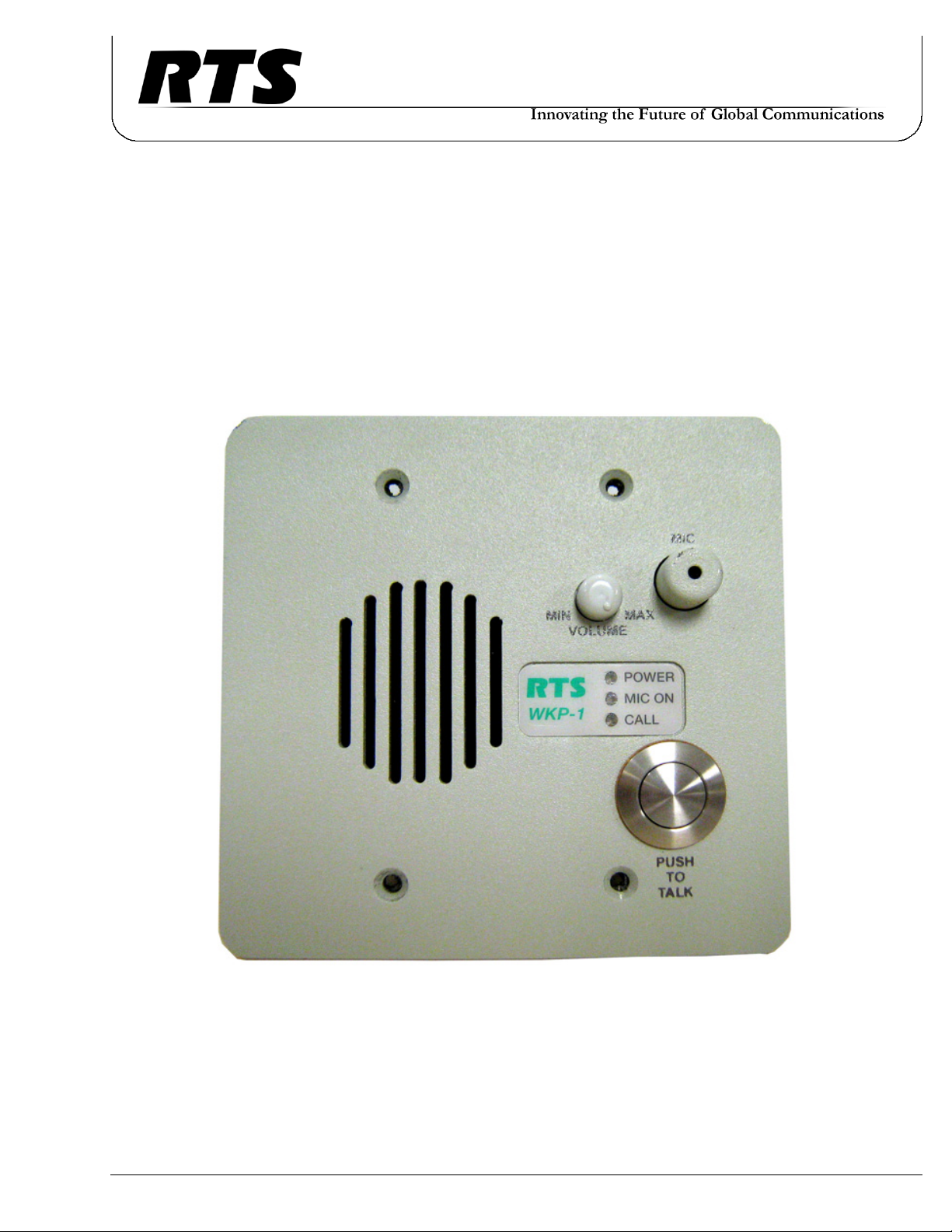
WKP-1
Digital Matrix Intercom System
Industrial Keypanel
F.01U.193.272
Rev. 08
September/2017
Page 2
2 WKP-1
PROPRIETARY NOTICE
The product information and design disclosed herein were originated by and are the property of Bosch Security Systems, Inc.
Bosch reserves all patent, proprietary design, manufacturing, repro
duction, use and sales rights thereto, and to any article disclosed
therein, except to the extent rights are expressly granted to others.
COPYRIGHT NOTICE
Copyright 2017 by Bosch Security Systems, Inc. All rights
reserved. Reproduction, in whole or in part, without prior written
permission from Bosch is prohibited.
*All other trademarks are property of their respective owners.
WARRANTY AND SERVICE INFORMATION
For warranty and service information, refer to the appropriate web
site below:
RTS Intercoms .............................. www.rtsintercoms.com/warranty
RTS Digital
RTS TW
AudioCom
RadioCom
Intercom Headsets.....................................................www.telex.com
-
THE LIGHTNING
FLASH AND
ARROWHEAD
WITHIN THE
TRIANGLE IS A
WARNING SIGN
ALERTING YOU OF
“DANGEROUS
VOLTAGE” INSIDE
THE PRODUCT.
SEE MARKING ON BOTTOM/BACK OF PRODUCT.
WARNING: APPARATUS SHALL NOT BE EXPOSED TO DRIPPING OR
SPLASHING AND NO OBJECTS FILLED WITH LIQUIDS, SUCH AS VASES,
SHALL BE PLACED ON THE APPARATUS.
WARNING: THE MAIN POWER PLUG MUST REMAIN READILY OPERABLE.
CAUTION: TO REDUCE THE RISK OF ELECTRIC SHOCK, GROUNDING OF
THE CENTER PIN OF THIS PLUG MUST BE MAINTAINED.
WARNING: TO REDUCE THE RISK OF FIRE OR ELECTRIC SHOCK, DO NOT
EXPOSE THIS APPRATUS TO RAIN OR MOISTURE.
CAUTION: TO REDUCE
THE RISK OF ELECTRIC
SHOCK, DO NOT REMOVE
COVER. NO USERSERVICABLE PARTS
INSIDE. REFER
SERVICING TO
QUALIFIED SERVICE
PERSONNEL.
THE EXCLAMATION
POINT WITHIN THE
TRIANGLE IS A
WARNING SIGN
ALERTING YOU OF
IMPORTANT
INSTRUCTIONS
ACCOMPANYING
THE PRODUCT.
CUSTOMER SUPPORT
Technical questions should be directed to:
Customer Service Department
Bosch Security Systems, Inc.
www.rtsintercoms.com
TECHNICAL QUESTIONS
Bosch Security Systems Technical Support
http://www.rtsintercoms.com/contact_main.php
DISCLAIMER
The manufacturer of the equipment described herein makes
no expressed or implied warranty with respect to anything
contained in this manual and shall not be held liable for any
implied warranties of fitness for a particular application or
for any indirect, special, or consequential damages. The
information contained herein is subject to change without
prior notice and shall not be construed as an expressed or
implied commitment on the part of the manufacturer.
WARNING: TO PREVENT INJURY, THIS APPARATUS MUST BE SECURELY
ATTACHED TO THE FLOOR/WALL/RACK IN ACCORDANCE WITH THE
INSTALLATION INSTRUCTIONS.
This product is AC only.
Page 3

WKP-1 3
Important Safety Instructions
1. Read these instructions.
2. Keep these instructions.
3. Heed all warnings.
4. Follow all instructions.
5. Do not use this apparatus near water.
6. Clean only with dry cloth.
7. Do not block any ventilation openings. Install in accordance with the
manufacturer’s instructions.
8. Do not install near any heat sources such as radiators, heat registers, stoves,
or other apparatus (including amplifiers) that produce heat.
9. Do not defeat the safety purpose of the polarized or grounding-type plug. A
polarized plug has two blades with one wider than the other. A grounding
type plug has two blades and a third grounding prong. The wide blade or the
third prong are provided for your safety. If the provided plug does not fit
into your outlet, consult an electrician for replacement of the obsolete outlet.
10. Protect the power cord from being walked on or pinched particularly at
plugs, convenience receptacles, and the point where they exit from the
apparatus.
11. Only use attachments/accessories specified by the manufacturer.
12. Use only with the cart, stand, tripod, bracket, or table specified by the
manufacturer, or sold with the apparatus. When a cart is used, use caution
when moving the cart/apparatus combination to avoid injury from tip-over.
13. Unplug this apparatus during lightning storms or when unused for long
periods of time.
14. Refer all servicing to qualified service personnel. Servicing is required
when the apparatus has been damaged in any way, such as power-supply
cord or plug is damaged, liquid has been spilled or objects have fallen into
the apparatus, the apparatus has been exposed to rain or moisture, does not
operate normally, or has been dropped.
Page 4

4 WKP-1
Page 5

Table
of
Contents
DESCRIPTION AND SPECIFICATIONS ................................................................................. 7
General Description .................................................................................................................................7
Features .................................................................................................................................................... 7
Front Panel Description ...........................................................................................................................8
Specifications ...........................................................................................................................................9
INSTALLATION ........................................................................................................................ 11
Unpacking and Inspection .....................................................................................................................11
Installation and Mounting ......................................................................................................................11
Dip Switches ..........................................................................................................................................12
Address Switch ......................................................................................................................................13
Zeus Intercom Systems ..................................................................................................................................... 13
ADAM CS Intercom Systems ........................................................................................................................... 13
ADAM CS with RJ-12 Back Panel ................................................................................................................ 13
ADAM CS with 50-pin Telco Back Panel ..................................................................................................... 14
ADAM Intercom Systems ................................................................................................................................. 14
Gain Control ..........................................................................................................................................15
Change Gain Settings with the Application Setup ............................................................................................ 15
Run in Half-Duplex Mode ................................................................................................................................. 16
Talk Latch Disabled .......................................................................................................................................... 16
The Three (3) WKP-1 Boards ................................................................................................................ 17
Contents ............................................................................................................................................................. 17
Connections ...........................................................................................................................................18
KEYPANEL SETUP ................................................................................................................... 21
Intercom Key Operation ........................................................................................................................21
Volume Adjustment .......................................................................................................................................... 21
Momentary vs. Latching Operation .................................................................................................................. 21
Intercom Key Operation for Different Key Assignments ...................................................................... 22
Talk or Listen Key Operation ............................................................................................................................ 22
Special Functions .............................................................................................................................................. 22
Talk+Auto-Follow (AF) Listen Key Assignment .......................................................................................... 22
Talk+Auto-Listen (AL) Listen Key Assignment ........................................................................................... 22
Talk+Auto-Reciprocal (AR) Listen Key Assignment ................................................................................... 22
Intercom Key Indications .......................................................................................................................22
Mic On Indicator ............................................................................................................................................... 22
Incoming Calls .................................................................................................................................................. 23
Operation with the TIF Telephone Interface .........................................................................................23
WKP-1 Final Assembly .........................................................................................................................24
Page 6

6 WKP-1
Page 7

CHAPTER 1
Description and Specifications
General Description
Bosch has refined the look of multi-location security with the WKP-1 Industrial Keypanel. It offers simplified operation and
integrates seamlessly with digital intercom systems (ADAM, Zeus, Zeus III and ADAM-M). The physical size and
weather-resistant design provide a flexible, robust intercom system. The GPI (General Purpose Input) relay switch allows the
user to set up door latching, unlatching, and other related actions by pressing a single button from any panel in the system.
Features
Environmental - The unit sustains exposure to rain, snow, and direct sun, allowing it to work in all
environments. This keypanel operates in temperatures ranging from -30°F (-34°C) to
111°F (44°C). The mechanical design of the aluminum front panel and non-removable
volume control knob provide a tamper-resistant product.
GPI Relay - The WKP-1 has a local GPI relay 4-pin terminal contact closure to give the user the
functionality such as latching, unlatching doors and other related functions with the
press of a button.
Front Panel - Single button interface for push-to-talk operation. There is a built-in, water-resistant
speaker for listening capabilities. The panel has three (3) LEDs used to indicate power
on, microphone on, and incoming call signaling.
Microphone - The WKP-1 has a built-in water-resistant electret microphone. The microphone can be
hot-mic enabled or disabled through the use of a dip switch setting.
Keypanel Assignment - All key assignments, GPIO operations, and panel listen/muting functions are set for the
intercom system through AZedit software.
Audio Control - The front panel volume controls adjust the internal speaker listen level. An internal limit
adjustment sets the lower level of minimum volume achievable.
Audio Processing - An integral limiter/compressor insures the maximum intelligibility of the spoken word.
The compressor uses the Bosch standard compression design.
Dual Power - The keypanel can be powered locally through the 3-pin terminal or remotely via an
RJ-45 connection from the breakout panel or remote power supply.
Page 8
8 Description and Specifications WKP-1
Front Panel Description
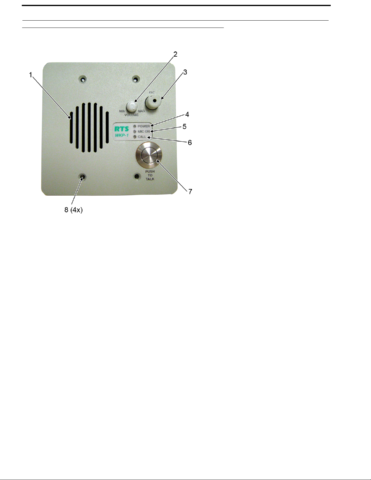
FIGURE 1. WKP-1 Reference View (Numbered items refer to front panel descriptions)
1. Speaker - The speaker is built-in and water-resistant to allow for dependable listening. An internal
volume control allows the user to set a lower limit on the volume level, ideal for loud
environments, such as loading docks and construction sites.
2. Vol u me C o ntro l - Controls the listen level of the speaker.
3. Microphone - Built-in, water-resistant, Electret microphone. The push-to-talk button allows a user to
talk into the microphone and be heard at the other end of the connection.
4. Power Indicator LED - A green LED appears when the keypanel is on
5. Mic On Indicator LED - A green LED appears when Mic On is active.
6. Call Indicator LED - The PUSH TO TALK button activates the microphone for use and a green LED is seen.
7. Push-To-Talk Button - Used to switch the microphone on to enable the user to talk to the matrix.
8. Mounting Holes - The mounting holes fit any standard, 2-gang electrical box (3” depth minimum). The
electrical box is not included.
Page 9

WKP-1 Description and Specifications 9
Specifications
Matrix
Input/Output
8dBu nominal, 16dBu maximum
Panel Mic Input
Mic Type
Electret Condenser
Nominal Level
-44dB ±3dBu
Directivity
Omnidirectional
Speaker
Output
3 Watts
Power Requirements
15VDC 400mA nominal (800mA maximum) for local power. 24VDC up to 800mA for remote power 300ft or more.
Connections
RJ-45
For use with Standard CAT-5 cabling
RJ-12
For use with RTS Matrix Standard 3-pair cabling
Terminal strip for use with unterminated cabling
Size
Width
4.562” (115.87mm)
Length
4.5” (114.3mm)
Depth
2.525”(64.14mm)/2.7” (68.58mm) with cable attached
NOTE: The keypanel fits a standard 2-gang, 3” deep electrical box.
Page 10

10 Description and Specifications WKP-1
FIGURE 2. WKP-1 Industrial Keypanel size requirements
TABL E 1 . Connector Pinouts
Pin Terminal Strip RJ-45 RJ-12
1 RS-485+ Audio_IN + Data-
2 RS-485- Audio_IN - Audio from Matrix+
3 NC GND Audio to Matrix+
4 Audio_OUT+ RS-485+ Audio to Matrix-
5 Audio_OUT- RS-485- Audio from Matrix+
6 NC Power Data+
7 Audio_IN+ Audio_OUT+ N/A
8 Audio_IN- Audio_OUT- N/A
Page 11

CHAPTER 2
Installation
Unpacking and Inspection
As soon as possible after receipt, inspect the package and its contents for physical damage that may have occurred in shipping.
If damage has occurred, immediately (within 24 hours) contact the carrier involved and file a claim. Save all packing materials
and request an immediate inspection by the carrier’s insurance claims agent.
The package should contain the following items:
1 - WKP-1 Industrial Keypanel
1 - WKP-1 User Manual
Installation and Mounting
The WKP-1 mounts directly into a standard 2-gang electrical box. The electrical box must be at minimum three (3) inches
deep to accommodate the stacked design of the PC boards (see
Figure 2).
Page 12

12 Installation WKP-1
Dip Switches
Dip Switch 1
Open Latching turned on. (default)
Closed Latching turned off.
Description An intercom key can always be turned on for momentary conversation by pressing and holding
the key during the conversation. There is also an electronic latching feature that lets you tap
intercom keys to turn them on or off. This permits convenient hands-free conversation. However,
it can also result in a talk circuit being left on unintentionally. For example, a key that talks to a
public address system could be accidentally left on. Or, an IFB key (a type of key assignment
often used by a security advisor to give instructions to a user) could accidentally be left on,
causing confusion for the listener.
The latching feature can be turned off to prevent such accidents.
Dip Switch 2
Open 15-second flash after incoming call is received (default).
Closed LED flash until caller releases key.
Description Whenever there is an incoming call and there is a talk key assigned to the caller, the talk LED next
to that key flashes. The flash can be set for 45 second
time-out, or until the caller’s talk key is released.
Dip Switch 3 Reserved
Dip Switch 4
Open The hot mic is disabled (default)
Closed Audio from the microphone leaves the panel at all times.
Description When enabled, the audio flows out of the keypanel independent of the talk key position.
Page 13

WKP-1 Installation 13
Address Switch
A rotary switch is used to indicate the logical port address the keypanel uses to communicate with the Matrix. The switch is
read continuously by the Matrix through polling. If the port address is changed, the new address is effective immediately.
NOTE: By default, the address port is shipped with an invalid address to ensure there are no conflicts with existing
keypanels. It is important to set the address port for the WKP-1 keypanel for it to function properly
In Zeus, ADAM, ADAM CS and ADAM-M intercom systems, intercom ports are arranged in groups of eight (8). Within each
group, each WKP-1 keypanel is uniquely identified by its address switch setting.
FIGURE 3. Address Switch
The address switch has a white pointer that points to the current switch setting. Use the following paragraphs to determine the
proper settings.
NOTE: The address switch settings 9 through F, and 0 are not used.
•
ADAM Intercom Systems
Each AIO card contains two groups of eight intercom ports. However, the individual intercom ports may be broken out using
various types of breakout panels or punch blocks, and group may not be easily identified. It may be easier to set the WKP-1
address switch using the actual intercom port numbers.
REFERENCE: To address the WKP-1, refer to the address table in the ADAM user manual. Locate the intercom port
number to which the WKP-1 is connected to. Then, read across to the address column to find the address
number. Set the WKP-1 address switch to this number.
NOTE: The address switch settings 9 through F, and 0 are not used.
Page 14

14 Installation WKP-1
Gain Control
FIGURE 4. System Diagram depicting gain control
The WKP-1 Industrial Keypanel is susceptible to a feedback squeal due to the placement of the mic in relation to the speaker.
When this occurs a continuous audio loop forms which creates a feedback or squeal. For example, in Figure 4, audio enters the
mic in the WKP-1, goes to the Matrix, then out the speaker on the KP-32. If the mic on the KP-32 is on, the sound emitting
from the speaker may be picked up by the mic and sent back to the Matrix and to the WKP-4, thus creating an audio loop.
However, if at some point within that loop a break occurs, due to the half-duplex mode or gain control settings, the loop cannot
complete and the feedback is not heard.
There are several ways to reduce audio feedback:
• Change Gain Settings with the Application Setup
• Run in Half-Duplex Mode
• Talk Latch Disabled
Change Gain Settings with the Application Setup
There are several different points within the system setup where the user can set the gain control so as to limit the mic or
speaker sensitivity to reduce the occurrence of feedback. The gain control can be modified in the WKP-1, in the Matrix on the
crosspoints (using AZedit), or in the keypanel on the other side of the Matrix. For example, if the purpose of the industrial
keypanel is to overhear work being done in a warehouse, which may or may not be close to the speaker, the sensitivity of the
speaker must be set to pick up audio from a distance. And, since the main use of the keypanel is listen, the mic gain control is
set low so as to not allow the speaker to pick up any audio.
For more information on how to set the gain control within the WKP-1, see “Gain Control” on page 14.
Page 15

WKP-1 Installation 15
Run in Half-Duplex Mode
Half-Duplex Mode allows the transmission of audio data in just one (1) direction at a time, whereas full-duplex mode allows
transmission in both directions at the same time. Because the WKP-1 does not support half-duplex mode, the half-duplex
mode must be setup on the keypanel at the other end of the transmission. Setting the keypanel in half-duplex mode forces a
break in the audio feedback loop. In half-duplex mode the user can either listen or talk, but cannot do both at the same time.
These configurations are done in AZedit. Auto-reciprocal allows listen to be on all the time and allows talk to be turned
on and off. This reduces feedback because talk is only on when the talk button is pressed, thereby not allowing audio through.
Auto-mute is also a way to reduce feedback through the system. When auto-mute is utilized, listen automatically turns off
when the talk button is pressed.
Talk Latch Disabled
Talk Latch Disable is another way in which the audio feedback can be reduced. Talk Latch allows the user to push a keypanel
button once and talk is turned on. When Talk Latch is disabled, the talk function only works when the button is pressed. The
user can disable the talk latch button through AZedit or set dip switch 1 to close in the WKP-1 dip switch settings (see
Switches” on page 12).
“Dip
FIGURE 5. The middle board in the WKP-1 (also referred to as the audio board).
There are three (3) gain control pots that can be configured to reduce feedback. Turning the gain control clockwise increases
the gain level; turning it counter-clockwise decreases the gain level.
• R213 controls the gain for the speaker
• R103 controls the gain for the mic
Page 16

16 Installation WKP-1
The Three (3) WKP-1 Boards
FIGURE 6. WKP-1 3-dimensional view of boards.
Contents
Front Board
1. Reset Button - The reset button provides a hardware reset to the processor.
2. Dip Switches - Set the dip switches to individual preferences (see “Dip Switches” on
3. Rotary Address Switch - The rotary address switch assigns a port address in which to communicate with
Middle Board
4. 4-Internal Volume Setting
Pot (213) -
Back Board
Connections - RJ-12, CAT-5 and local power (see Figure 5 on page 15).
page 12).
the Matrix (see
“Address Switch” on page 13).
The internal volume pot is located on the middle board. It controls the lower
limit of the audio to the speaker.
Page 17

WKP-1 Installation 17
Connections
FIGURE 7. Connections Board of the WKP-1.
NOTE: The numbered descriptions correlate with the numbers in the Figure 7.
1. GPI Relay Contact 4-pin Terminal (J500)
2. Local or Remote Power Switch (SW100)
3. Local Power 3-pin Terminal (J100)
4. RJ-45/CAT-5 Connection (J300)
5. RJ-12 Connection (J400)
6. 8-pin Terminal (J200)
NOTE: If you are providing your WKP-1 keypanel with remote power, use the WKP-1 BOP (see Figure 10 on page 25).
Page 18

18 Installation WKP-1
FIGURE 8. DE-9P Male to DE-9S Female
FIGURE 9. CAT-5 (RJ-45 Intercom Cable Wiring Diagram
TABL E 2 . GPI Relay Terminal Pin Assignments
Pin Channel
1NO
2C
3NO
4C
NOTE: By default the channels are always open.
Page 19

You can only make keypanel assignments using AZedit.
REFERENCE: For more information on AZedit, see the AZedit user manual.
Intercom Key Operation
CHAPTER 3
Keypanel Setup
Vol u m e Ad ju s tm en t
Adjust speaker volume with the volume control.
Momentary vs. Latching Operation
For momentary key activation, do the following:
> Press and hold the intercom key.
For latching operation, do the following:
1. Tap the intercom key to turn it on.
2. Ta p t h e intercom key again to turn it off.
NOTE: If the LED next to a key does not turn on when the key is activated, this means the key is not currently
assigned. The electronic latching feature (dip switch 1) must be enabled in order to use latching. See “Dip
Switches” on page 12.
Page 20

22 Keypanel Setup WKP-1
Intercom Key Operation for Different Key Assignments
Talk or Listen Key Operation
The PUSH-TO-TALK button activates talk (if assigned). Listen cannot be activated from the WKP-1. The user can only listen
when a different keypanel is talking to it.
Special Functions
Talk+Auto-Follow (AF) Listen Key Assignment
This key assignment works the same as the basic talk/listen key assignment. The PUSH-TO-TALK button activates talk. Talk
may be turned on or off independently by pressing and or releasing this button.
Talk+Auto-Listen (AL) Listen Key Assignment
The push-to-talk button activates both talk and listen. However, only the talk LED turns on, you cannot turn off listen. If talk is
off, you can turn listen on independently by pressing up.
Talk+Auto-Reciprocal (AR) Listen Key Assignment
The PUSH-TO-TALK button activates talk. Listen is always on and continuously monitors whatever is assigned to the talk
position.
Intercom Key Indications
Mic On Indicator
Solid Green Indicator - Talk is active.
Continuous Red In-Use Indicator - An in-use indicator is provided for an IFB key. It is also provided for a key that
talks to a remote intercom system (when your intercom system is equipped with
optional trunking). The in-use indicator warns you that someone else is currently
talking.
Red Flashing Busy Indicator - May occur when the talk key is activated to talk to an IFB or a remote intercom
system. This indicates that some other keypanel with a higher priority is currently
talking and you cannot talk at this time. Once calls have been answered, the green
LED next to the call waiting key turns off.
Page 21

WKP-1 Keypanel Setup 23
Incoming Calls
Green Flashing LED Indicator - This means another user on the intercom system is calling. Press the PUSH-TO-
TALK button to answer the incoming call.
The mic on or call LED indicator flashes to indicate an incoming call to the keypanel.
• If tally is disabled, the LED indicator is only enabled for 45 seconds before it stops and returns to
normal operating mode.
• If tally is enabled, the LED indicator is enabled as long as the push-to-talk button is not pressed.
When a call comes to the keypanel, the incoming call LED indicator is activated and flashes. At this point, if the PUSH-TOTALK button is pressed, it acts as a CWW (Call Waiting Window) reply key. The user can respond to the incoming call rather
than only being able to talk to the preassigned talk key.
There is a 45 second time-out to reply to the incoming caller. Once the 45 second time-out has elapsed and the PUSH-TOTALK button is no longer pressed, the panel returns to normal operation.
NOTE: The 45-second time-out does not mean that after 45 seconds the user cannot continue talking with the incoming
caller if the PUSH-TO-TALK button is still pressed. It means that after 45 seconds, if either the incoming caller
or the WKP-1 disconnects normal talk key assignments are restored.
Page 22

24 Keypanel Setup WKP-1
Page 23

25 Keypanel Setup WKP-1
FIGURE 10. WKP-1 BOP System Diagram
Page 24

26 Keypanel Setup WKP-1
Page 25

WKP-1 Keypanel Setup 27
Page 26

Bosch Security Systems, Inc.
12000 Portland Avenue South
Burnsville, MN 55337 U.S.A.
www.boschcommunications.com
 Loading...