

Page 1
TECHNICAL MANUAL
I
MODEL
TW
Interface Units
TM3600
TW1222
1
OIN
9300-360040
Including
TW1222-T
TW1222-CM
TWI-SK7O-DCU
1
~~12241
Intercom System
A
Telex
RTS SYSTEMS
Communications Product
Page 2
TECHNICAL
MANUAL
Model TWI224
PROPRIETARY NOTICE
The information and design disclosed herein were
originated by and are the property of RTS Systems.
RTS Systems reserves
manufacturing, reproduction, use an sales rights
thereto, and to any article disclosed therein, except to
the extent rights are expressly granted to others.
COPYRIGHT NOTICE
Copyright
USA.
in part without written permission from RTS Systems
is
prohibted.
1988
by
ALI
rights reserved. Reproduction in whole or
all
patent, proprietary design,
RTS Systems, Burbank, California,
/TWI222
Interface Units
AND
UNPACKING INFORMATION
Immediately upon receipt of the equipment, inspect
the shipping container and the contents carefully for
any discrepancies or damage. Should there be any,
notify the freight company and the dealer at once.
The shipping Model
should
Ordering Number 9000-2195-00
Ordering Number 9000-2184-00
a
contain
RTS Systems
Part Number Descriotion
9010-2195-00 Model TWI224
9010-2184-00 Model TWI222
9300-3600-00 Technical Manual
TWI224
the following components:
/
TWI222 container
INSPECTION
--
TWI224
--
TWI222
Printing History:
First Edition: July 1980
6
Second Edition: July 1989
This manual
Department of RTS Systems, whieh is responsible for
its contents.
Written by: Daniel
Edited by:
Address
to:
Director of Engineering
RTS Systems
1100 West Chestnut Street
Burbank,
is
published by the Engineering
F.
Register
Sheryl D. Thompson
all
communication regarding
CA
91506 USA
this
publication
RTS Systems
Burbank,
CA
91506 / FSCM: 60572
Page
ii
TM3600
/
Second Edition, July 1989
Page 3
TECHNICAL
Model
TWI224 / TWI222
TABLE OF CONTENTS
MANUAL
Interface
Units
Unpacking Information
Table
Of
Contents
warranty
Shipping Information
SECTION
1.1
U
13
SECTION
Ref. No Ti&
21
22
23
2.4
sEClTON3: OPERATING INSTRUCTIONS
.......................
1:
INTRODUCTION
Introduction
Application
Spedbtiions
2:
INSTALLATION
RTS TO 4-Wue
RTS To 2-Wue Systems
RTS To
RTS To
.............................................................................................................................................
.......-
.........................................................................................................................................
"...,.,
...........
-......---.-
.........
...........................................................................................................................................
AND
SPECIFICATlONS
...........................................................................
Guide
..............................................................................................................................
........................................................................................................................................
Cameras
2-Wm
RCAPaven
Telephone
and
Intercoms
...................................................................................................................
Wetpry
Systems
...........................................................................................................
"."--"-.."."
.-..................
"
....................................................
................................................................
...............................................................................................
............................... I ....................................................................
'
1
"
.....
"
....
..
n
...
m
v
v
1-1
1-1
1-1
2-1
22
2-3
2-5
3.1
3.2
3.3
3.4
SECI'ION
Ref.
4.1 Introduction
4.2 Fuuctid Dwcription
4.3
4.4
Introduction
RTS To 4-Wue Systems Operation
RTS To 2-Wire System Operation
RTS To 2-Wire Telephone Operation..
4:
TBEORY
No Title
TWI-222
Circuit
RTS Systems Burbank,
.....................................................
OF OPERATION
...................................................................................
Block
Description
Description
....................................................................................................................................
"
...........................................................................................
........................................................................................................
....................................................................
.
.................................
..................................................................................................
.........................................
..............................
..............................................................................................
...................................................................................................................
CA
91M6
/
FSCM:
Page
6057%
iii
TM36GU
/
Second Edition,
July
3-1
3-1
3-1
3-1
4-1
4-1
4-2
4-2
1989
Page 4

Model
TECHNICAL
TwI22a
/
Twrm
MANUAL
Interface
Units
SECTION
Ref. No Title
5.1
SECTION
Ref. No Title
5:
Chaghg
6.
Introduction
How To Obtain Parts
Shipping
Fi
Back Panel mbly
Front Panel Assembly
Printed Cuaut Assembly
Fd
S-ON
7:
Document
Number
MAINTENANCE
Impedance
LISTS OF
.........................................
REPLACEABLE
..................................
PARTS
........................................................................................................ 6-1
......................................................................................................................
Lists
Assembly
...........................................
........................................................................................................................................
...............................
. .
Assembly, Model
DIAGRAMS
Schematic Diagram,
Assembly
Assembly
Engiaeering Note,
wkhg
TWI-SK70-DCU,
sheet
2
Schematic Diagram, TWISK70-DCU
Assembly
TWI-SKnrDCU, Squelch
sheet 2 of
TWISKMDCU
sheet 2 of
Schematic
Assembly
Schematic Diam,
...............................................................................................................................
..............................................................................................................................
TWUZZ
Diagram,
Diam,
Diagram, TWISK70-DCU
of
2
.....
"
......
Diagram, TWI-SK7DDCU
2
......
"
..............................................................................................................................
2
........................................
Diagram,
Dim,
......................... " ...................................................................................
Interuun Interface
P.C.B.
TWU24
P.C.B.
TWI224
TWISK70DCU
4-Wue Interface W/SAP
"
."
............................
Circuit Piggyback
Squelch
Card,
Squelch Mod For
P.C.B. Squelch M&cation
Intercom Interface
........................................................................................
"
..............................
"
.............................................................................
TWI220
Interface Layout
Hold Circuit Layout
Interface Card
Interface
,,
1024,
"
......
.................................................................................
............................................
Layout
Board
Circuit Description sheet 1 of
.."
....
"....
..
..............................................................................
TWI-SK70-DCU
TwI22a
...............................................................
................. - ..............................
..................................................................
...........................................................
...................................................................
......................................................
sheet 1 of
Chart
........................
Installation
2
...................................................
"
...........................................
"
........................................
to
Interface
2
.............................................
..........................................................
For
TWISK70-DCU
.......................................................................
.......................
Card
Layout
.....................
"
...................
..............
...................
5-1
6-1
61
6-1
6-2
6-2
6-2
6-4
7-2
7-3
74
7-5
7-6
7-7
7-8
7-9
7-10
7-11
7-l2
7-I3
7-14
7-l5
7-16
7-17
RTS
Systems
Burbank,
CA
91M6
/
FSCM:
Page
60572
iv
TM3600
/
Second
Edition,
July
1989
Page 5
TECHNICAL MANUAL
TWU24
Model
SYSTEMS'
RTS
The
produds of RTS Systems, , a California ProcedureForRehuns:
corporation, are warranted to be
materials and workmanship for a
from
the
date
of
RTS Systems'
period
neees~ary to remedy mvered defects appearing in
produds returned prepaid to RTS Systems,
a
Chestnut
This
warranty doas not mver any defect, malfunction
or failure
including umeasonab1e or negligent operation, abuse,
accident, failure to follow
defective
at
moditidon and repair not authorized
Systems, and shipping
serial
numbers removed or effaced are not awered
this
warranty.
To obtain warrauty
entitled "PROCEDURE FOR
THIPPING
OR
ADJUSTMENT listed below.
This
warranty
warranty given
It
is
the
responsibility of
purchase
intended
sole
to provide, without
Street, Burbank, CaliFomb,
cad
or
improper associated equipment, attempts
TO
with
that
this
purpose.
LIMITED
WARRANTY
Free
from defects in
period
sale.
obligation during the warranty
beyond
service,
charge,
the
control of RTS Systems,
instructions
damage.
follow
parts and labor
91U)6,
in
this
Products with their
the
RETURNS"
MAN~A~FOR~REP~~-
is
the
sole and
respect to RTS
the
user to determine before
product
is
exclusive
Systems'
suitable for
/
TWI222
of one year
1100
W.
USA.
Manual,
by
RTS
by
pdures
and
pr
3'-
ucts.
the
user's
Interface Units
RETURN
If
repair
is
unit
was
purchased
IF
repair
through
RTS Systems Customer Service Department, located
at the factory,
Return Authorization Number
DO NOT
FACIY)RY
RElURN
Be prepared to provide your wmpany's name,
address,
the repair, the
description of
oUwtio11~ regarding returns for repair should be
directed to:
SHIPPING TO MANUFACIVRER FOR REPAIR
phone number, a person to contact regarding
SHIPPING INSTRUCTIONS
neeeasary, contact the dealer where
the dealer
as
directed below. They
RETURN
WITHOUT
AUTHORIZATION
type
the
defect, and
Customer Service Department
RTS Systems,
1100
W.
Burbank,
Telephone:
Telex:
TeletaX
OR ADJUSTMENT
is
not possible, phone the
will
ANY
EOWIPMENT TO
FIRST
OBTAINING
NUMBER,
and quantity of equipment, a
the
serial
number(s).
Chestnut
CA
194855
(818)
St.
91506,
USA
(818) 8407311
843-7953
this
issue
THE
a
A
ANY
INCLUDING
MERClUNTABlLlTY
DURATION
AND
ALL
THE
OF
IMPLID
IMPLIED
ARE
THIS
WARRANTY
LIMITED TO THE
EXPRESS
WARRANTY.
NEITHER
WHO SELIS
LIABLE
CONSEQUENTIAL DAMAGES OF
RTS
SYSTEMS
RTS
SYSTEMS'
FOR INCIDENTAL OR
RTS Systems Burbank
NOR
CA
WARRANTIES,
LI~~ED
TEE
DEALER
PRODUCTS
ANY
IUND.
91506
/
FSCM:
All
OF
IS
page
shipments of RTS Systems, equipment should
p&
shpper. The equipment should be shipped
original pacldng cartoa;
suitable
a substitute
be
four inches of excelsior or
material.
attention of the Customer Service Department and
must include the Return Authorization Number.
Upon com letion of repairs equipment
returned
shipper.
60572
v
via
container
wrapped
Th9600
United Parcel Service or the best available
if
that
is
not available,
that
is
rigid and of adequate
container
in
All
shipments should
S
/Second Edition, July
is
used,
the equipment should
paper
and
surrounded
similar
via
United Parcel Service or specified
shock-absorbing
be
directed to the
1989
with
be
in
the
use
any
size.
at least
will
be
If
Page 6
Model
TECHNICAL MANUAL
TWI224
/
TWI222 Interface
Units
SECTION
SPECIFICATIONS
The
designed to interface RTS Systems'
other interwms. These interfaces derive operating
power from the RTS line, and are transformer
isolated to prevent ground loop interference.
package styles
style
a wnsole mount package. The rack mount version
may be ordered
panel
13
This
interface for your application.
The
system to a four wire intuwm system.
include some teldon broadcast cameras, the
MeCurdy interwm systems, radiotelephones, and
cameras
(except for
camera
or two wire mode,
TWI222 interface.
better performance..
interface
RING-SLEEVE jack on
however better performance
TWI222-CM connected directly to the Carbon Mic
system's line.
2RTSTW"systemsover2telwdrypairs.
prefered to
1:
INTRODUCTION
TWU22
similar
APPLICATION GUIDE
section is intended to help you
TWU22
and
TWIZL4
are
available - a wmpact portable
to our belt
with
interface is for interfacing an RTS
which
have waxial or
the
Hitachi
has
the option of operating in either four wire Biiteral Current Sources
use
This
The
to
a Carbon Mic system
Two
TWI222's
using
2
TWI222-Ts
series of interfaces are
packs,
a rack-mount style, and
up to
three
trkial
SK-70
the
will
with
four
result in easier
TWU22
the
Carbon
will
can
over
AND
"TW"
system to
Three
interfaces in one
select
the wneet
This
would
cable adapters
DCU).
wire
mode and our Peak Current
may
also
through
be
achieved
be
used
telephone
If
your
set
up and
be
used
a
TIP-
Mic
system,
using
to interface
Thisis
lines.
to
used
TWI222 to be
from
25
ohms to
The TWI222-CM is designed to interface an RTS
"TW"
system directly to an RCA/DAVEN type
ca~bon mimophone intercom system, with an
impedance of
determine the ad impedance of your system,
divide
120
by
the number of stations on the line. For
example,
impedance of
The TWI222-T is
system to a 2-wire wet telephone line. It includes an
electronic hold circuit.
13
Typ'ncal
Balance
Input/Output Voltages:
120
10.9
SPECIFICATIONS
Gain:
Null
Capabiity
with a
1600
ohms.
4-16
ohms (30 to 7 stations). To
divided
ohms.
designed
Drive.
a
line
by
11
14
20
-30 dBm to
10
impedance ranging
stations yields a line
to interface an RTS
to
20
dB each direction
dB
+10
dBm
mA
(200
ohms)
The
TWI222 interfaces are for interfacing an RTS
two
system to other
TWU22
the
The
systems to interwm systems
200
The
is supplied in
TWI222,
TWU22
ohms nominal, with a range of
impedance may be user selected, allowing the
the TWI222-CM, and the TWI222-T.
is designed to interface RTS
RTS Systems Burbank,
wire intercom systems. The
three
different wnIigurations,
with
a line impedance of
100
to
CA
91506
400
/
7%'"
ohms.
ESCM.
Page
60572
1-1
Th9600
/
Sewnd Edition, July
1989
Page 7
Model
TECHNICALMANUAL
TWI22A
/
TWI222
Interface
Units
SECI'ION
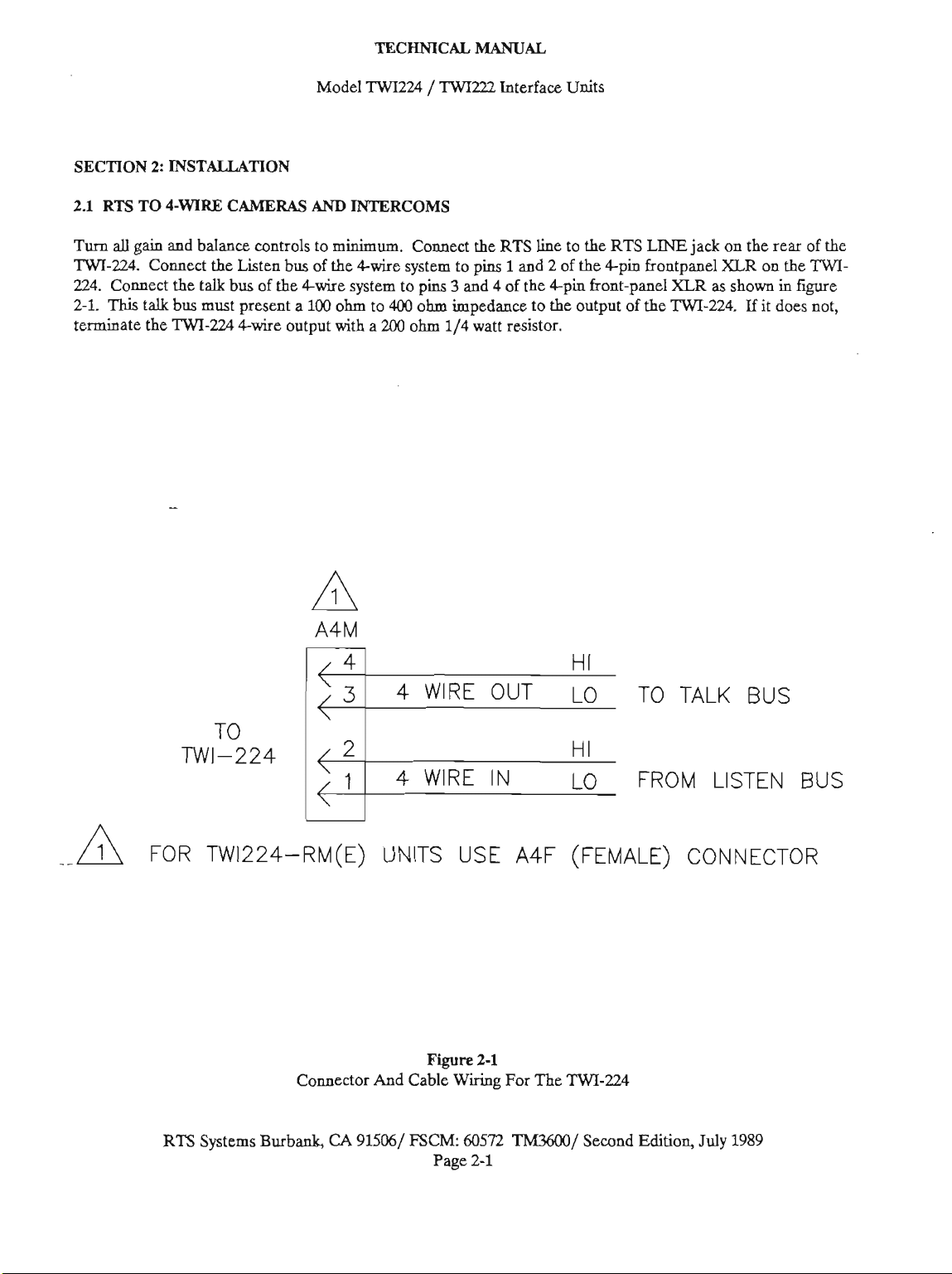
2.1
Turn
TWI-224.
224.
2-1.
terminate the
2:
RTS
TO
d
gain
Conneb
Coaned the talk
This
talk
INSTALLATION
&WIRE
and balance cont~oIs to
bus must present
TWI-224
WLMERAS
the Listen bus of the 4-wire system to pins
bus
of
4-wire output with
AND
INTERCOMS
minimum.
the
4-wire system to pins 3 and 4 of the 4-pin front-panel
a
100
ohm to
a
400
200
Connect
ohm
ohm
114
the
RTS
1
impedance
watt
resistor.
line to the
and
2
to the output of
RTS
of the +pin frontpanel
LINE
XLR
the
TWI-224.
jack
on the rear of the
XLR
on the
as
shown in figure
If
it does not,
TWI-
TO TALK BUS
4
WIRE IN
-
FOR W1224-RM(E) UNITS USE A4F (FEMALE) CONNECTOR
RTS
Systems Burbank,
Fire
Connector And Cable
CA
915061
FSCM
Wiring
Page
2.1
60572
2-1
For The
TWWO/
LO
FROM LISTEN BUS
TWI-224
Second Editioq
July
1989
Page 8
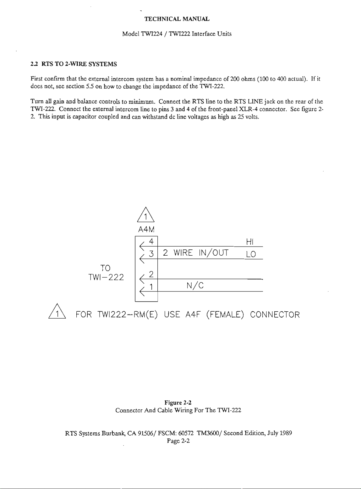
22
RTS
TO
2-WIRE
SYSTEMS
Model
TECHNICAL MANUAL
lWE24
/
TWI222
Interface
Units
First cob that the
does
not,
see
section
Turn
all
gain
and balanffi controls to minimum.
TWI-222.
2.
This
Conned
input
is
the
capacitor coupled and
external
55
intercom system
on
how to change the impedance of the
external
intercom line to pins 3 and 4 of the front-panel
can
has
Connect
withstand
4
<
3
a nominal impedance of
TWI-222.
the RTS line to the RTS
dc
line
voltage-s
2
WIRE IN/OUT LO
as
high
2QO
as
ohms
LINE
XLR-4
25
volts
HI
(100
to
400
jack
on the rear of the
wnnector.
actual).
See
figure
If
it
2-
2
:
1
-
FOR TW1222-RM(E) USE
RTS Systems
Connector
Burbank,
CA
And
915061
Cable
Figure
FSCM:
Page
A4F
23
Wiring
60572
2-2
N/C
For The
TM3600/
(FEMALE) CONNECTOR
TWI-222
Second
Edition,
July
1989
Page 9
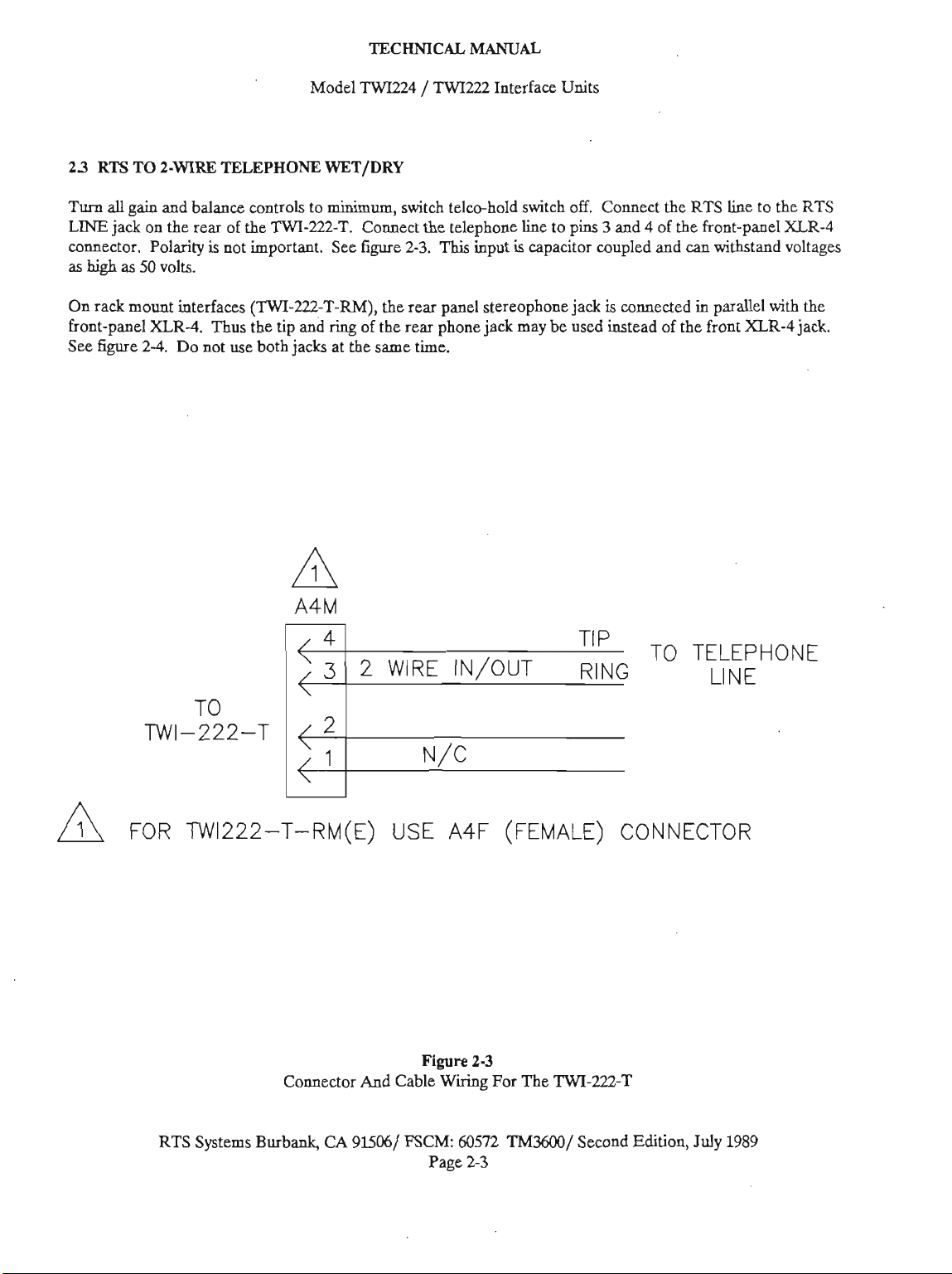
23
RTS
TO
2-WIRE
Turn
all
gain
and balance controls to
LJNE
jack on the rear of the
~~nnedor.
as
high
Polarity
as M volts.
Model
TWI224 / TWI222
TELEPHONE
TWI-222T.
is
not important. See figure
WET/DRY
minimum,
Connect the telephone line to pins 3 and 4 of the front-panel
TECHNICAL
switch
tebhold switch oE Conned the
2-3.
This
MANUAL
Interface
input
is
capacitor coupled and
Units
RTS
line to the
can
withstand voltages
RTS
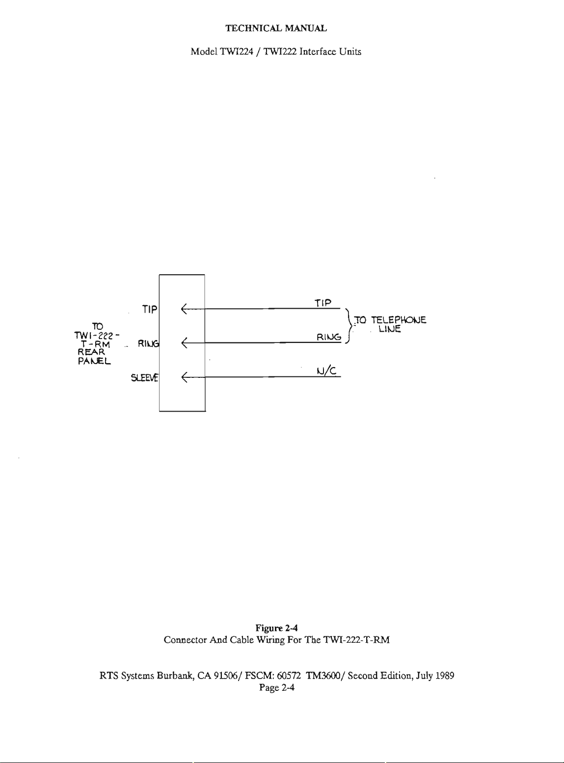
XLR-4
On rack mount interfaces
front-pel
See
figure
XLR-4.
2-4.
Do
Thus
not
use
(lWI-222T-RM),
the
tip and
both
jacks
ring
of the rear phone jack may
at
the
-
4
<
3
2
<
2
<
1
the rear panel stereophone jack
be
used
same
time.
WIRE IN/OUT
N/C
is
connected in parallel
instead of the front
TIP
TO TELEPHONE
RING
XLR-4
LINE
with
the
jack.
FOR TW1222-T-RM(E) USE A4F (FEMALE) CONNECTOR
RTS
Systems Burbank,
Fire
Connector And Cable
CA
915061
FSCM:
Wiriag
Page
23
60572
2-3
For The
TMbCQ/
TWI-222-T
Second
Edition,
July 1989
Page 10
Model
TECHNICAL
lWI224
/
TWI222
MANUAL
Interface
Units
TO
TWI-222-
T-RM
REAR
PANZL
-
RI
TO
TELEPKNJE
RTS
Systems Burbank,
Connector
CA
And
Cable
91506/
Figure
Wi
FSCM:
60572
Page
2-4
For
2-4
The
TWI-m-T-RM
Th9600/
Second
Edition,
July
1989
Page 11
2A
RTS
TO
RCA/DAVEN
Model
SYSTEMS
TECHNICAL
TWI224
/
TWI222
MANUAL
Interface Units
TWI-224
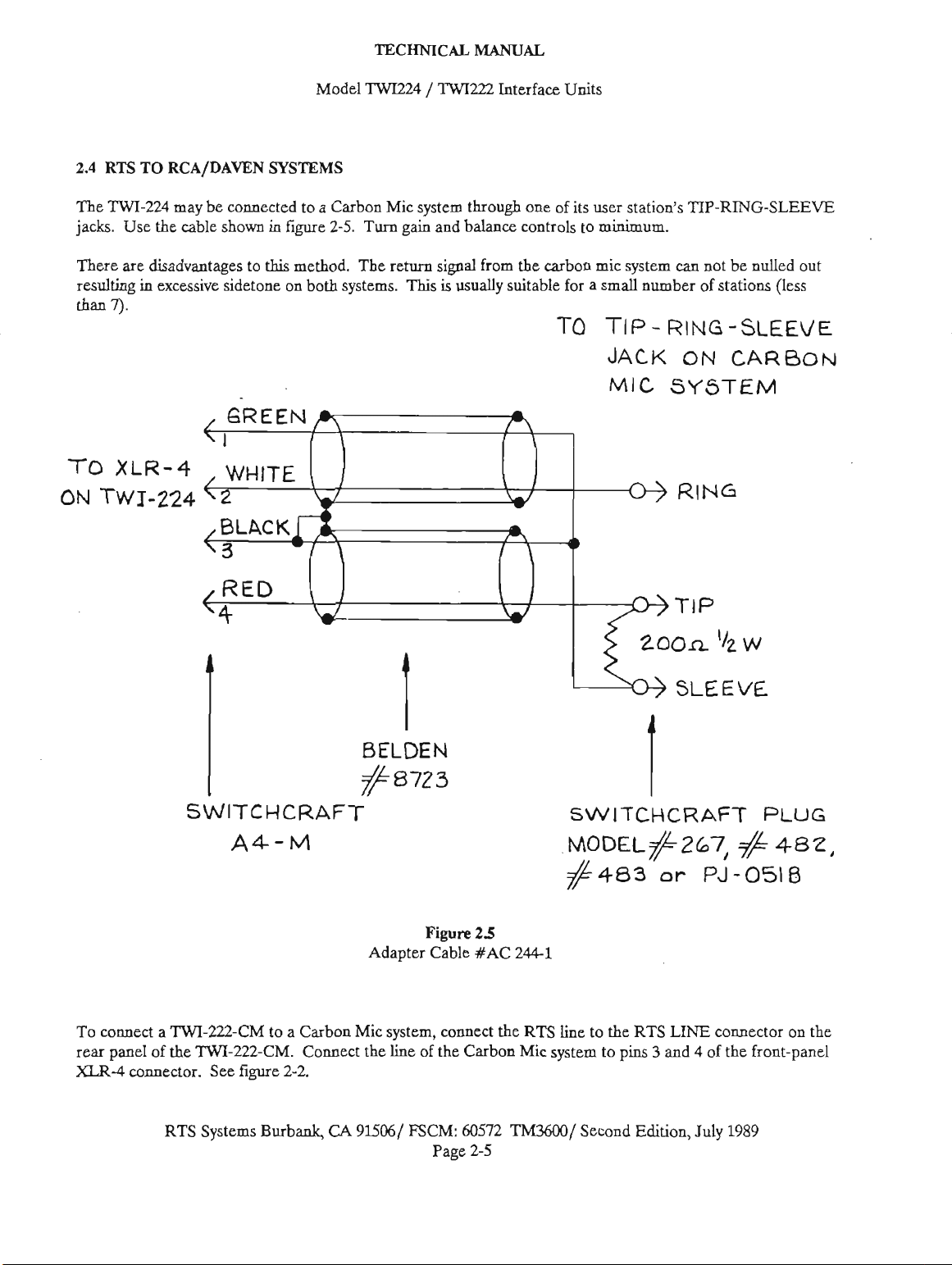
The
jacks. Use the cable shown
are
There
resulting
7).
than
TO
XLR-4
ON
TWI-224
may
be
disadvantages to
in
excesiw
sidetone on both
wnnected to a Carbon
in
figure
25.
Turn
this
method. The return
systems.
Mic
system through one of
gain
and balance controls to minimum.
signal
from
the
carbon
This
is
usually
suitable for a
TO
its
user station's
mic system
small
TIP
JACK
MIC
TIP-RING-SLEEVE
can
not be nulled out
number of stations (less
-
RING
-SLEEVE
ON
CARBON
SYSTEM
To WMed a
rear
panel of
XLR-4
conneetor. See figure
SWITCHCRAFT SWITCHCRAFT
A4-M
TWI-22Z-CM
the
TWI-222-CM.
RTS Systems Burbank,
to a Carbon
Connect the
2-2
Adapter Cable XAC
Mk
Sysrem, connect the RTS line to the RTS
line
of the
CA
9W/
FSCM:
Figure
Carbon
605'72
Page
2-5
25
244-1
TM3MX)
~0~~~8267,
#483
Mic system to pins 3 and 4 of the front-panel
/
Second Edition,
or
LINE
July
PLUG
#
482,
PJ-0518
wmector on the
1989
Page 12

SECllON
3.1
3:
INTRODUCTION
TECHNICAL
Model
TWU24
OPERATING INSTRUCTIONS
/
TWI222
MANUAL
Interface Units
After making connections as desaii in section
is
the unit
describes how to adjust and operate
installations
system
readjustment may
32
RTS
After making the dons described in don
set
all
to minimum.
system on Establish that both systems are operating
properly.
Plug a carbon miaophone headset into
MIC ONLY jack located on the rear panel.
Increase the GAIN FROM RTS to
Hum into the carbon miaophone and adjust
BALANCE FROM RTS until
obtained.
With
one person
on the &wire system, adjst the GAIN controls
both people
33
RTS
After making
se3
all
GAIN and BALANCE controls on the
to minimum.
Zwire system.
operating properly.
Plug a carbon miaophone headset into the
CARBON-MIC-ONLY jaek on the
ready to
dadbed
is
adjusted, any
TO
4-WIRE
GAIN and BALANCE controls on the
Turn
can
hear
TO
2-WIRE
the
Turn
be
adjusted.
This
each
in
don
part
be
required. minimum.
SYSTEMS OPERATION
power to the RTS and the 4-wire
on
the RTS
each
other clearly.
SYSTEM
comeetions desaid in sectinn
on the
Con6nn
power
2
4
after
of the system changes, Decrease the GAIN FROM RTS control to
the
CARBON
50%.
the.
best null
"rW"
line and another
OPERATION
to the RTS and the
that
both systems are
rear
2
section and adjust
of the
the
2%
TWU24
is
until
22
TWI222
of the
TWI222.
Set the BALANCE FROM RTS control
approximately
Inaease the GAIN FROM RTS control to maximum.
50%.
to
Speak or hum into
the
a null
is
obtained.
Use an RTS user station to listen on the RTS system.
Turn
the
microphone off and volume to maximum.
Increase the GAIN TO RTS to maximum.
Adjust the BALANCE TO RTS control for a null in
the
noise as heard on the RTS system.
Reduce
The
taken not to disturb the balance controls.
improperly balanced interface may oscillate.
Set both
Have
through
person
3.4
After
turn
gain
system on and verify that the system works.
Plug a carbon miaophone headset into the CARBON
MIC ONLY
rack mount versions ('IWKZI-T-RM)
jack
Set the BALANCE FROM RTS control to
approximately
Increase
the
GAIN TO RTS to minimum.
interface
gain
controls to approximately
two people establish two-way communication
the interfaec; adjust
can
be
RTS
TO
2-WIRE
making the wnnections described in section
the
TEE0 HOLD switch off and
controls to minimum.
jack on the rear of the TWIlU-T. On
is
on the front panet
the
GAIN FROM RTS control to maximum.
the
carbon microphone headset
BALANCE FROM RTS control
is
now balanced and care should
25%.
the
gains
so
that each
heard clearly.
TELEPHONE OPERATION
all
level and
Turn
power to the RTS
the
carbon mic
50%.
until
be
An
23,
RTS Systems Burbad,
CA
91506 / FSCM:
Page
60572
3-1
TM3600
/
Seeond Edition, July
1989
Page 13
TECHNlCAL
Model
TWIZ24
Speak or hum into the carbon microphone headset
and adjust the
a
null
is
BALANCE
obtained.
FROM
RTS control
/
until
MANUAL
TWU22
Interface
Units
Decrease the
minimum.
Use
an RTS user station to listen
Turn
the microphone off
Increase the
Adjust
the noise
Reduce the GAIN
The
taken
improperly balanced interface
Set both
Have
through
person
the
as
interface
not to
gain
two
the
can
GAIN
GAIN
BALANCE
heard
is
now balaaced and
disturb
controls to approxhately
people establish two-way wmmunication
interface; adjust the
be
heard
FROM
and
TO
RTS to maximum.
TO
on
the RTS system.
TO
RTS to minimum.
the
dearly.
RTS control to
on
the
RTS
volume to maximum.
RTS control
balance wntrok.
may
for
care
odate.
25%.
gains
so
a null in
ahodd
that each
system.
be
An
RTS Systems Burbank,
CA
91M6
/
FSCM:
Page
60.572
3-2
Seaond
Edition,
July
1989
Page 14
TECHNICAL
Model
TWI224 / TWI222
MANUAL
Interface
Units
SECTION
4.1
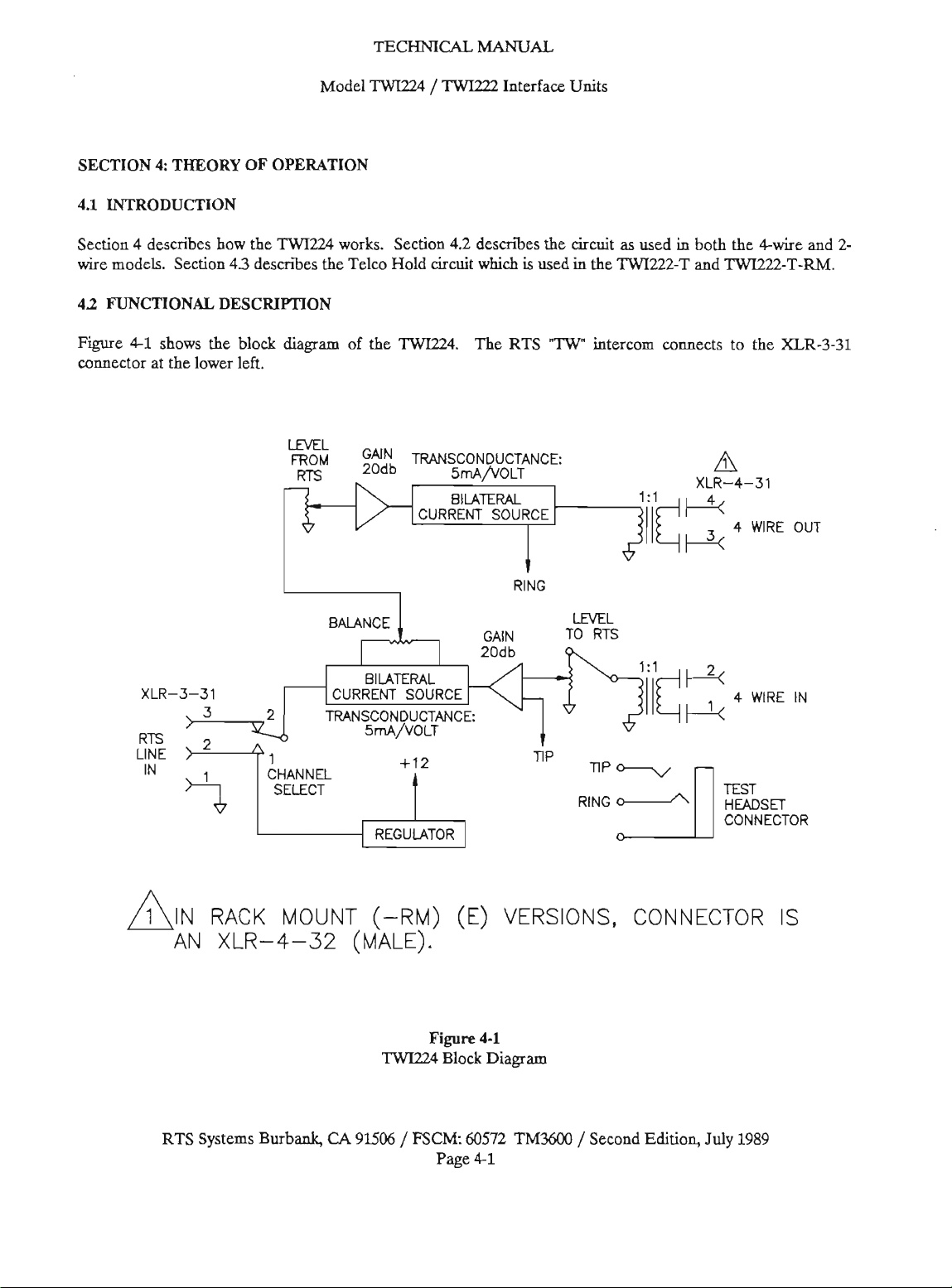
Section 4 deseni how the
wire
43
Figure
eonnebm
4:
THEORY OF OPERATION
INTRODUCTION
models.
FUNCTIONAL Dm-ON
Sedon
4-1
shows the block
at
the lower lett
43
describes
TWI224
the
diagram
LML
works. Section
Telco Hold circuit
of the
TWI224.
CURRENT SOURCE
42
desuibes the circuit
which
is
used
The
RTS
"ZW"
5mAfiOLT
RING
GAIN TO
as
used
in
the TWI222-T and
intercom
LEVEL
RTS
comects to the
in
both the We and
TWI222-T-RM.
XLR-3-31
'A
XLR-4-31
2-
XLR-3-31 CURRENT SOURCE
RTS
YiE
IN
RACK
AN
XLR-4-32
RTS Systems Burbank,
MOUNT
(-RM)
(MALE).
CA
9U06
TWI224
/
WCM:
(E)
Figure
Block
Page
VERSIONS.
4-1
Diagram
60572
Th9600
4-1
CONNECTOR
/
Second Edition,
July
1s
1989
Page 15

TECHNICAL
Model
TWI224
Power to operate the intertace
channel
RTS interwm passes through the channel select
switch to
bilateral current source presents a
impedance to
balance pot
This
system.
Next
the input of
output passes through a
bus
current source must
ohms.
impedance to
resistor must
The
wnnedor
LEVEL
ic
input of a bilateral current source. Output from the
current source
input. One end of the BAL4NCE control wnnects to
the input while the other end connects to the output
Thus
of-phasc output
return to the &Wire system
return to the &Wire system would mean too much
sidetone on the
does not affect sidetone on the RTS system.
1.
Audio from either channel
the
output of a biieral current source. The
the
RTS line.
and
sent to the LEVEL FROM RTS pot.
control sets the level going to
an
ic
provides
another
of the external 4-Wire system. The output of
If
the external interwm does not present
be
4-wire
passes
TO RTS pot. The output of the
amplifier with a
at
some point in the middle of
20
the
4-wire
used.
input of the front-panel
through a
is
inverted when compared to the
will
Si
dB
of
biikteral current source. The
1:l
be
terminated
output, an external
gain
of
cancel
the input such that the
is
4-wire
system. The balance control
is
derived from
1
or
high
is
picked off
the
external
gain.
This
signal feeds
transformer to the talk
with
100
1:l
transformer to the
pot
20
dB.
This
the
pot the out-
miaimizcd.
Too
/
2 of
the
input
of
the
4-wire
this
to
400
this
200
ohm
-431
feeds an
feeds the
much
TWIZ22
MANUAL
Interface
Power for the interface
a
special regulator circuit.
Audio from RTS passes through the BALANCE
FROM RTS pot to the LEVEL FROM RTS pot.
The
signal
This
feeds the bilateral current source.
Output from the current source drives
wire
interwm through a
is
inverted.
The BALANCE TO RTS wntrol wnneds to both
the input and
the pot
cancel. It
null or feedback
Input from the external 2-wire interwm enters the
TWIZZL
signal
The
LEVEL
RTS system.
ampli6er. Output from
bilateral current source
RTS line.
Again
signal wming from
feedback oscillation
The test headset jack
the RTS line
the external interwm
able to speak to, the person
Units
is
derived from channel
is
then amplitied
the
inverted output. Near the center of
is
a place where the out-of-phase signals
is
important to set the balance wntrol for
will
occur.
through the front-panel
is
picked off of the BALANCE TO RTS pot.
TO
RTS pot sets the level going to the
20
dB
the balance wntrol must
the
will
with
a carbon-mic headset. Persons on
20
dB
by
an
ic
amplifier.
the
external 2-
kl
transformer.
of
gain
is
provided by
the
amplifier feeds another
which
provides oulput to
be
external interwm system or
result.
is
connected to talk and listen to
will
not hear, nor
using
the test headset.
This
output
XLR43L
set to null the
will
they
1
with
The
an
will
i.c
the
be
a
The test headset wnnedor provides a wnvienent way
to balance the system. It
listen to the RTS system, with a carbon-mic headset,
just
as
if
it were another station on the 4-wire system.
43
lWEl2
Fwe 4-2
similar to the
wntrols and only one transformer.
BLOCK
is
the block
he
RTS Systems Burbank,
is
wnneeted to tak and
DESCRIPTION
diagram
except there are two balance
for the
CA
TWI222
91506 / FSCM:
It
Page 4-2
4.4
CIRCUIT DESCRIFTION
This
section describes the circuit operation of the
TWIZL4.
power
power
wall-plug transformer
The power supply of the
from channel 1 of
(LP)
is
CR2
provides reverse current protection while
acts
as
a
fuse
catastrophic unit failure.
60572
TM36Ofl/
lWIZ4
the
RTS line except for local
units
which
derive
with
on severe overvoltage conditions or
Sewnd Edition, July
their
an output of
derives its
power from a
14
volts dc.
1989
R30
Page 16

Model
TECHNICAL MANUAL
TW1224
/
TWU22
Interface
Units
RTS
XLR-3-31
3
RTS
-7
CHANNEL
SELECT
+*
IN
RACK MOUNT (-RM)
AN XLR-4-32 (MALE).
CURRENT SOURCE
+12
1
REGULATOR
(E)
LEVEL
WIN
20db
A
TO RTS
A
'4
CONNECTOR
VERSIONS, CONNECTOR IS
RTS
Systems
Burbank,
CA
TWU22
91506
/
FSCM.
Figure
Block
60572
Page
4-2
Diagram
4-3
TM3600
/
Secnnd
Edition,
July
1989
Page 17

TECHNICAL
MANUAL
Model
4A
CIRCUIT
VR2
proteds the unit from excessive line voltage
shunting anything over
voltage spikes
unplugged from the RTS line at once.
The output of U2
U2 should read
output (0)
C25
slows down the current response. of U2.
keeps the input to U2 a
does not "short out" the audio on
provides filtering.
Q1
is
provides
filtering.
Audio from the RTS intercom enters through the
rear-panel
C20
and
of the capacitance.
C20
and
pass low frequencies. If they did not, the output level
of the bilateral current source would go up and
circuit would bceome unstable.
DESCRIPl'ION (continued)
36
volts to ground.
can
occur
when many user stations are
is
set
for U volts
12
volts between
terminals.
high
impedance so that it
the
a constant current source to
6
volts to
XLR-331 (lower
(29.
C29
bias
the
op amps.
left)
and
These
capacitors are large because hal£
is
lost
by
their bipolar arangement.
must
also
be
large because they must
TWI224
by
R32 and
the
adjust (A) and
RTS line.
VR1
C28
is
decoupled
/
TWIm
by
High
R31.
This
C26
which
provides
by
the
Interface Units
The
signal
continues through
through the wiper. RllA
the signal through
amplifying stage
U1
is
designed to operate with a bipolar power
supply. By biasing the inputs to
operate on
biasing
Ulb
is
feeds the external intercom through
with the
with
connected for k2 step up.
low frequencies.
Audio from the
(upper right) to Ulb, the output of a bilateral current
source. From
RTS) it
it joins
TWI222.
keep the circuit stable.
Uld
is
the current source that feeds the RTS line.
_&
is
done
another bilateral -nt source whose output
-CM
a 200:8 transformer.
passes
RZSA
R29
has
a gain of 10 (20 dB).
C7
to U1.
with
a gain of 10 (20 dB).
single-ended
by
R10 and
(carbon mic) option,
extemal
the
wiper
throd
(lower
and CU roll off
C30,
right). T1
R23,
C18 and RllB
(GAIN
intercom enters through
of
FROM
This
part of U1
+6
volts, the i.c
+
12
volt supply.
the
6
volt source.
T2.
T2
-T
(Telco) units have
CL
is
large in order to pass
R25B
(BALANCE
jumps
to
point 18 1 where
is
not used in the
low
frequencies to
This
feeds Ula
RTS) sends
is
For units
is
replaced
which
an
can
This
T2
T2
TO
The
signal
continues through C19 to
bilateral current source at
large for the same reason
It
is
there
to block dc from channel belect switch
This
eliminates
The
output of the bilateral current source presents a
high
impedance to the incoming
because a bilateral mnt soum converts a
voltage input to a
"current source". When the input voltage
varying, ie. no input,
In order for
the circuit must follow the voltage variations
in the output
0 volts out). Thus
voltage coming in
impedance and does not load the line.
clicks
varying
the
output current to remain constant,
so
that no current
the
the
RTS Systems Burbank,
the
that
when switching channek.
current output. Hence
the
output current
circuit
output
the
output of
right of
C20
and
R26.
C29
signal.
will
is
drawn
(0 volts in
is
actively following
so
that it
CA
91506
are
is a high
C19
large.
This
varying
is
not
vary.
coming
/
FSCM:
the
is
SL
is
not
=
the
60572
Page 44
TM36Ml
/Second
Edition,
July 1989
Page 18

Model
TECHNICAL
TWllZQ
/
TWU22 Interface
MANUAL
Units
SECTION
5.1
CHANGING
5:
MAINTENANCE
IMPEDANCE,
APP
NOTE DR-501
(see
following
application
note)
RTS
Systems
Burbank,
CA
91M6
/
FSCM:
60572
Page
TMXXXX
5-1
/
Seumd
Edition,
July
1989
Page 19

Application Note
SUBJECT
APPLICATION:
GENERAL INFORMATION
SPECIFIC DATA CUSTOMER:
DATE
APP
PAGE
The
your system.
at the input and 200 ohms at the output.
interface to a 200 ohm line.
ohms nominal. In the 50 ohm mode, the interface
100 ohms.
When the interface
ohms.
Should you find that your system
200 ohms, change the TWI-222 or TWI-224 to match your system.
the drawing that applies to the change you want to make.
trace and add the jumper shown.
2/5/80
NOTE
1
impedance of the TWI-224
TWI-222 INTERFACE
&
TWI-224 INTERFACE
CHANGING
F
DR-101
OF
2
Normally, the TWI-224
In
the 200 ohm mode, the unit
IMPEDANCE
is
set
This may be changed to 50 ohms or 800
for 800 ohms,
may be changed to better match
is
built to interface 200 ohms
The TWI-222
will
will
is
handle 100 to 400 ohms.
it
will
some impedance other than
handle 400 to 1600
is
built to
handle 25 to
Find
Cut the
I
WIRE:
2
4
WIRE:
50 OHMS
50 OHMS OUTPUT FROM TWI-224
RTS
Systems
BurbqCA
91M6 / FSCM:
60572
Page
TMXXXX
5-2
/
Second
Edition,
July
1989
Page 20

1100
Nest
Chesrnul Streel Burbank Calrforn,a 91506 213 843-7022
Application Note
SUBJECT
APPLICATION
GENERAL INFORMATION
SPECIFIC DATA CUSTOMER.
DATE
APP NOTE
PAGE
2/5/80
2 OF 2
TWI-224 INTERFACE
CHANGING IMPEDANCE
=
DR-101
2 WIRE: 800 OHMS
4 WIRE: 800 OHMS OUTPUT FROM !LWI-224
RTS
Systems
Burbank,
CA
91506
/
FSCM:
60572
Page
TMXXXX
5-3
/
Second
Edition,
July
1989
Page 21

TECENICAL
MANUAL
SECTION
This
four sections: shipping
following the description of a part
62 HOW
Parts may
RTS Systems
1100 W. Chestnut Street
Burbank,
818-5666700
63
6:
LISTS
section
umk
TO
be
obtained
CA
91M6
SHIPPING
OR REPLACEABLE PARTS
parts
lists,
and instruetiom
list,
final
OBTAIN PARTS
LIST
dLedly
-
from Customer Service, RTS Systems:
TWD24
Model
assembly, back panel and printed circuit board
is
lWIZZ4
the manufacturer and the
/
TWI222
for
ordering replacement parts. The parts
Interface
manufacturer's
Units
assembly.
part
number.
lists
are divided into
Immediately
rn
L
1
63.1 SHIPPING
1
1
6A
DESCRIPTION
Model
Model
Instruction
FINAL
DESCRIPTION
Washer, Teflon Swtrom
Saew 8-32 x 112" lWe Flat
Pot, Audio
Pot, DL lOK/lOK
Transformer, Audio Boa
Knob,
Knob,
TWI224
Instruction
TWll22
ASSEMBLY
Cap, .Oluf/lKv
#73
Shield Bead Fairrite 2673OLW1
Sii
Dual
Interfaw
Manual
LIST
-
Interface
Manual
Taper
C.D.
Blk 114"
Blk
lWUZZ
-
lWIZ24
10K Bourns 8lAlA-BsDl5
"CP"
1/4"
(W10-2195-00)
561237-40
HD
AB
26M9U7
Use
l51ORlU32R
LM9003
Alco
K700B
Ah,
K5700B
Phil
NKL
PL ST
RTS PART NUMBER
RTS
PART NUMBER
RTS PART NUMBER
RTS Systems Burbank,
CA
91506
/
FS(3M:
Page
60572
6-1
TM3600
/
Second Edition,
July
1989
Page 22

6.5
BACK
PANEL ASSEMBLY
Model
-
'IW12U
TECHNICAL
TWI224
/
/
TWU24
TWI2ZZ
MANUAL
Interface
(9020-178800)
Units
DESCRIPTION
Washer, 378ID, 6WD, Switchaaft S10451
Nut, Hex Kep
Nut, Hex, 318"
4-40
Screw
Cap, Mono .luf/50v
Conn.
Carbon
Cone
3
Corn
3
Wq 24AWG, blue vinyl, stranded,
Wue, 24 AWG, black vinyl, stranded,
Wire, 24 AWG, brown vinyl, stranded,
Wue, 24 AWG, red vinyl, stranded,
Wire, 24 AWG, green vinyl, stranded, 9
Wue, 24 AWG, blue vinyl, stranded,
Back Panel, STD BP/TWI Per FAB 1511-1 / FD23l9
6.6
FRONT PANEL ASSEMBLY
DESCRIFTION
Lug, Solder #4 Smith 14144
Nut, Hex Kep
Nut, Hex 318" 1007-000300
ScrewWx3/8" lOode.FLHD, C/R,BRWHZinc 1008-4012-00
Switcb, Toggle, SPDT Alco MTM-106DPC
Conn.
4
Wue, 24 AWG, blue vinyl, stranded,
Wire, 24 AWG, brown vinyl, stranded,
22
Wue,
Dress Nut Stain
Front Panel
4-40
x
318" lOOde
Mic.
Pi
male Neutrilr NC3MP
Pin
Female
4-40
Pi
Female Cannon
AWG, Buss 100 roll, Belden 8021
TWI2ZZ
FL
HD,
.1
Spacing, 1" length
Switchaaft MNl14B
Hirase
Fi
-
IBT
/
TWI224
HA16PR-3S
1WU22
AXR
W-NU-17A
FAB DWG U75, FD2181 9070-2181-00
C/R, BR WH
3"
3"
9"
9
9"
/
l%'J224
4-31
5"
5"
318"
O.D.
RTS PART
zinc
(9020-219300)
PTS
PART
NUMBER
1006-0031-00
1007-0001-00
1007-00M00
100&4012-00
1511-R104-21
mu-oao2~
m~-ccm-oo
mi&M)36oo
25ll-0001-00
2.511-0002-00
2511m
2511-001560
2511-001800
2511-004200
9080-2319-00
NUMBER
100UXX)4a0
1007-0001-00
m3-0106-PC
2018-0001-02
2511-0005-00
2511M)06-00
2512-OM2-00
2709-000300
6.7
PRINTED
DESCRIPTION
Teflon Sleeving
2
7 Res.
7 Res.
4
1
1
Res.
Res.
Res. CF 11K ohm 1/4w 5%
Res.
CIRCUIT
CF
100 ohm 1/4w
CF
1K
CF
l00k ohm 1/4w 5%
CF
l00K ohm 1/4w 5%
CF
12K ohm 1/4w
RTS Systems Burbank,
ASSEMBLY
20
AWG Alpha
5%
ohm 1/4w 5%
5%
-
CA
1WU22
TFT
9-
/
IwIu4
200-20,
/
FSCM:
Page
Roll
60572
62
(9030-2196-02)
PTS
PART
'I'M3600
/
NUMBER
Second Edition,
July
1989
Page 23

6.7
PRlN'IED
Model
CIRCUIT ASSEMBLY
TECHNICAL MANUAL
TWIVa
-
'LWU22
1
TWU22
/
lW'I224
Interface
(9030-219602)
Units
DESCRIPTION
Res.
CF
2OK
ohm
1/4w 5%
Res.
CF
22K
ohm
1/4w 5%
Res.
CP
22
ohm
1/4w 5%
Rcs.CF36ohm1/2w5%
Rw
CF
33
ohm
1/8w 5%
RW.
CF
470
ohm
114~ 5%
Rw
CF
4.7K
ohm
1/4w 5%
Cap,
.Oluf/lhr
Cap,
szOpf/lKv
Cap,
Mono
Cap,
Elec
Cap,
Elec
Cap,
Elec
Cap,
Elec
Cap,
Elec
Cap,
Elee
Cap,
Elec
Cap,
Mylar
Cap,
Mylar
Diode,
Diode,
Diode,
Diode,
Transistor,
Voltage Regulator, National
1.C-
I.C.
Transformer, Audio Bourns
Wire,
PCB,
Insulator
Natural Rubber
Outside
Ext.
Extrusion, Belt Pack
Outside
lN914B
IN4004 1 Amp,
lN5233A
lN5365B
MQ403P Motorola
Socket,
22
Ccm/m
Case,
C.D.
Ccr
.luf/50v
1m/16v
lOuf/lbv
lOuf/Mv
lOOuf/lOv
lM)Uf/Mv
2.2uf/Mv
47uf/l6v
.001uf/loOV
.0047/100V
Si
Voltage Regulator
Zener
J305
Siliwnix
14
Pin
AWG
Buss
FAB
w/out
holes
.062"
Profegsing
TWU22/224
Processing
Use
1510R1032R
Di
Radial
.1
spa*
Axial
Radial
Radial
Radial
Radial
Radial
Radial
Radial
WV
Voltage Regulator
Bmdy
1W
Roll, Belden
Per
FAB
Thick
Insulator
Per
6'
x
3
TWU22/224
1
length
10%
LM317MP
DU14P-108
LMwCn
Dwg
13nlAW2032
Per
Dwg
1840
x
3'
Wide
w/out
hole
Dwg
1802@D2318
112"
x
1
314"
Case
8021
RTS
PART
NUMBER
RTS Systems Burbank,
CA
91506
/
FSCM:
Page
60572
Th43bO4 / Second Edition,
6-3
July
1989
Page 24

68
FINAL
ASSEMBLY
DESCRIPTION
-
TWlZ22
TECHNICAL MANUAL
Model
TW1224 / TWI222
(9010-2lS4-00)
Interface
RTS
PART
Units
NUMBER
2
8
2
4
2
Washer,
Saw
8-32
Pot,
DL lOK/lOK
Y73
Shield
Knob,
Teflon
Dual
Seastrom
x
112"
loode
Bead
Fairrite
Blk 114"
5612-37-40
Flat
HD
Phil
NKL
PL
ST
"CP"
AB
26M907
26m1 24W-0001-00
Alco,
K5700B 270Z~B
1006-004400
10088031-M)
1407-
RTS
Systems
Burbank,
CA
91506
/
FS-
pago
60572
6-4
Th9600
/
Second
Edition,
July
1989
Page 25

SECTION
Document
N!mkz
7:
DIAGRAMS
Model
TECHNICAL
TWI224
/
TWU22
MANUAL
Interface Units
SDl255
ASl38l
MU79
EN#l38
mu67
EN#DR-500
ENXDR-m
SD1240
AS1241
APN#CN02
APNXCNUZ
APNBcN03
APN#CN03
SD1635
AS1762
SDl25S
Schematic Di, Intercom Interface
mbly Diagram, P.C.B.
Assembly Diam, P.C.B.
Fqheering Note, TWI-SKMDCU Interface
Wiring
TWISK70-DCU,
sheet
Schematic
Assembly
TWI-SK7&DCU, Squelch Circuit
sheet 2 of 2
TWISKMDCU Squelch
sheet
Schematic Diam, Squelch
Assembly
Schematic
Diagram,
2
of
2
Diagram,
2
of 2
Diagram,
TWISK70-DCU Interface
4-Wm
.............................................
Diam, TWISK70-DCU
....
-
.................................................................................................................................
...........................................
Diam,
TWI224
TWI224
Interface
TWI-SKMDCU Layout
Card,
Circuit Description sheet
Mod
P.C.B. Squelch
Intercom Interface
TWI224
Interface
Hold Circuit
W/SAP
--
................................................................................
,
........................................
Piiack
"
.......................................................................................
For TWISKMDCU
Modification
TW1224
........................................................................
Layout
..............................................................
Layout
Card
..........................................................
....................................................................
..............................................................................
1024, sheet 1 of 2
Chart
-.,."
Board Installation to Interface Card
...................................................
-
.....
.......................................
.......................................................
1
of
2
.............................................
..........................................................
For TWISK70-DCU Layout
...-...........-.
.......................................................................
..............
7-2
7-3
7-4
7-5
7-6
7-7
7-8
7-9
7-10
7-11
7-l2
7-l3
7-14
7-15
7-16
7-17
RTS Systems Burbank,
G4
91506
/
FSCM:
60572
Page 7-1
TIU3600
/
Second Edition,
July
1989
Page 26

RTS
Systems
Burbank,
CA
91W)6
/
FSCM:
Page
60572
7-2
TM3i%l/
Second
Edition,
July
1989
Page 27

Model
TECHNICAL
TWI224
/
TWI222
MANUAL
Interface
Units
NOTES:
RTS
3.
@
@
2.
C3\
I.MSUED
Systems
Ql,A5
EARLY
NOT
ON
-RD;
LINES INDICATE
Assembly
Burbank,
SHDWN,
VERSlONS;Ql,
IS
FCR
Dii,
CA
91506
J305
FUTURE
RM
/
FSCM:
(70-92
15
El05
USE.
ON
P.C.B.
Page
CASE)
(TO-IB
DOTTOM
TWI2.24
60572
7-3
PIN
CIRCLE)
Or
-0.
Interface Layout
'I'M3600
/
Second
Edition,
July
1989
Page 28

TECHNICAL
Model
~~1224
/
TwI222
MANUAL
Interfaffi
Units
RTS
Systems
CAM6104 X480-2970-02-03-00 SWAGE MD SOLDER PINS
BEFORE JNFFING
LAMP VPE
T- 1314
PARTY
APPLY
HOLD THEM IN PLACE.
NOTES
:
Assembly
Burbank,
THE
P.C. BOARD.
17M
:
28V,
W/RE
LEAD LAMP.
579
-17&4.
A
DROP OF CLEAR SILICON TO LAMP BASES TO
Diagram,
CA
91506
P.C.B,
/
FSCM:
.04A 34MSCP,SK IIR.,/NCANDESCENT
MOUNT LAMPS FLAT AGAINST RC.MIARD.
h,
1WI224
60572
Page
Hold
ThEWO
7-4
MOUSER ELECTRONICS
Circuit
/
Second
Layout
Edition,
July
1989
Page 29

__
4-
1100
Engineering
West
Chestnut
Note
Street.
Burbank Calrlornra 91506 213/643-7022
SUBJECT:
-
CARD
DATE:
TWI-SK7O-DCU INTERFACE
07-14-78
CUSTOMER: ALL USERS
ENGINEERING NOTE
PAGE:
1
of
2
#
:
138
OPERATION
SET-UP
1)
ISO/NORMAL switch to NORMAL.
2)
BALANCE control to center of range.
3)
Both GAIN controls to extreme counterclockwise position.
-
4) Plug in a carbon mic or Plantronics type headset into
the headset jack.
5)
Advance GAIN controls to approximately 1/3 of maximum
setting.
6)
Switch on microphone, say ahhhh and adjust BALANCE for
null in headphones.
7)
Move carbon mic headset plug to DCU "AUX" (INCOM) module.
8)
Set Headphone gain on "AUX" module midway. Set GAIN
controls on interface so that you and a person on the
RTS line can hear each other well.
9)
Vertify camera position can talk well with RTS line
(RTS belt pack gains set for normal two-way conversation
on RTS line).
ADDITIONAL COMMENTS
If there is distortion, check INCOM level settings in
Hitachi process pack.
The test jack in the interface module talks to the RTS
line but not the camera. Use the jack in the "AUX" module
to talk to the camera, and to talk to the camera when the ISO/
NORMAL switch is in the IS0 position.
RTS
System
~urbank,
CA
91506
/
FSM:
60572
Page 7-5
Th9600
/
Second
Edition,
July
1989
Page 30

Model
TECHNICAL
TWI224
/
TWI222
MANUAL
Interface
Units
CHROMA
KEY/RGB
J
13
HITACH1
REAR
DCU
VIEW
+
OUTPUT
AUX
("INCOM'
CARD
J9
CARD)
PLUG
INTO
RTS
THIS
RTS
CARBON
INTERFACE
SOCKET
Systems
Burbank, CA
EST.
Wiring
MIC
TEST
Diagram,
91506
/
4
WIRE
JACK
TWISK70-DCU
FSCM:
60572
Page 76
INPUT
Interface
TM3600
/
Second Edition,
July
1989
Page 31

1100 West Cheslnut Street
Burbank
Calrfornra 91506
213
843-7022
Engineering
SUBJECT
TWI-SK'IO-DCU
Note
4 wire interface with the SAP 1024
DATE
CUSTOMER
ENGINEERING NOTE
PAGE
For operation in the 4
to be converted to 4
01/29/80
1
of
2
=
DR-500
wire.
wire
mode.
the TWI-SK70-DCU card needs
To do this, move the zero-ohm jumper
shown below. Remove the jumper that goes from the balance pot wiper
(R15) to the
shown to the
y
0
#
L
0
GAIN
HI
ope
0%
r3"s-t
FROM
side
i
RTS pot (R16
of
Rl6.
HI).
--
Add
a
wire
from the point
--
om-
*-wk+s
-M
"=ul;.sr
To
KIL
YI
i
rrreO
.=,-0
"<
"8
r---q
L--->
Our-
Our-
0
Ou~cn
0
-0
01,.
;
I
a
DWb.
UJ%%I
ASIZ4I
0
0-
0
r3
-
"
n
)D
Y
Y
Q
I.
a.
RTS Systems
Burbank,
CA
91M6
/
FSCM:
Page
60572
7-7
TM3600
/
Second
Edition,
July
1989
Page 32

1lJLl
vt'es,
Cnesfnof Sfreef
Burbank
Cal#tarn8a
9';J6
2'3
8J3-7022
Engineering
SUBJECT
WI-SK7O-DCU
Note
4 wire interface with the SAP 1024
DATE.
CUSTOMER:
ENGINEERING NOTE
PAGE:
01/29/80
2
of 2
=
DR-500
For optimum performance with the SAP 1024, transformer T2
should be changed to a Bourns LM9001.
Terminate T1 with 430 ohms.
Also terminate the incom out with 430 ohms. To increase the gain,
up to 600 ohms may be used. To reduce the gain, as low as 100 ohms
,-
!
may be used.
Iru4.
sb
IelO
1151
a
-...--".7
-0-
."
I
IWML
ill-a"
Adjust the
is
the same
as
Adjust the
provide about
connector.
GAIN
FROM RTS pot so that the level on the RTS line
that of a regular user station.
GAIN
2
FROM RTS to about 1/4 of maximum. This should
volts peak to peak
signal
The levels in the SAP should be
The balance control no longer has any affect.
RTS Systems
Burbank,
CA
91M6
/
ESCM:
Page
60572
7-8
TM3600
at
pin 20 of the edge
set
for maximum gain.
/
Second
Editioq
~dy
1989
Page 33

TECHNICAL
MANUAL
Model
TWU24
/
TWI222
Interface
Units
RTS
Systems
Burbank,
Schematic Diagram,
CA
91506
/
FSCM:
Page
IWISK70-DCU
60572
TM3600 / Second
7-9
Edition,
July
1989
Page 34

Model
TWI224
TECHNICAL MANUAL
/
TWI222
Interface
Units
lil
NOTES:
RTS
OnJUMPERS
OPTION
\L
Systems
I.
Assembly
Burbank,
CA
91M6
Diagram,
/
FSCM:
IWI-SK70-DCU
60572
TM3600
Page
7-10
Layout
Chart
/
Second
Edition,
July
1989
Page 35

I
loo
Wesr Cleslnul Street
Application Note
Burbank
Cal~fornla 91506 213
843
7022
SUBJECT
INSTALLATION TO INTERFACE
APPLICATION
GENERAL INFORMATION
SPECIFIC DATA CUSTOMER.
DATE
APP NOTE
PAGE
The TWI SK70
for use on the RTS
058 and 51901-51950).
by the
the RTS PL/Intercom lines to remain operable and noise free.
mount the piggyback board, and five
board. One zerohm jumper
board. The trimpot on the squelch card controls the sensitivity of
the squelch.
DCU
Two mounting holes must be drilled into the main board to
TWI SK70 DCU SQUELCH CIRCUIT PIGGYBACK
CARD
TWI-SK7O-DCU
4/15/80
F
CN02
1
of 2
DCU
squelch circuit' piggyback board
TWI
when the
SK70
camera
Its
DCU
INTERFACE CARD
purpose
is
disconnected from the DCU and to allow
is
to
attenuate noise generated
wires
is
to be removed from the main interface
(serial
connect
it
BOARD
is
intended
numbers 001-
to
the main
The complete installation
1.
Place the main board, component side up. card edge fingers
pointed to the right.
2.
Drill
hand edge and 2.00 inches from the near edge
0.156 diameter hole
inches from the near edge. Accuracy
avoid interference with components on the main board or the card
guides.
3.
Using 4/40 hardware. and extra nuts
bring the
the squelch card (component side up) on the
securely, making
that the card caqe guides
4. Remove the zerohrn jumper, which, on the main board,
between pin 22 of the card edge fingers and
the
screws
first
up from the solder side of the main board, and mount
0.156 diameter hole 2.00 inches from the left
is
placed 4.00 inches from the left and 0.75
sure
that no
will
is
outlined below:
of
the board. The second
is
very important in order to
to
act
as
short stand-offs,
main
wires
not hit the piggyback squelch card.
are
pinched under the card and
R-1
(GAIN
card. Fasten
is
connected
TO RTS)
.
RTS
Systems
Burbank,
CA
91506
/
FSCM:
60572
Page
7-11
TFu13600 / Sewnd
Edition,
July
1989
Page 36

SmS
1100 -sf Chestnut Sfreet Burbank Ca,tlornta 91506 21.3843-7022
Application
SUBJECT
TO
INTERFACE
APPLICATION.
GENERAL INFORMATION
SPECIFIC DATA
OATE.
APP NOT
PAGE.
5.
Wire as follows: (see drawing no. 1869)
lcir&
1
2 from pad marked
3 from pad marked "GNDW to pint2 or pint44 (wire
4 from pad marked "+9" to CRZ, cathode
TWI SK70 DCU SQUELCH CIRCUIT PIGGYBACK BOARD INSTALLATION
CARD
TWI-SK~O-DCU
4(15/80
F
.
2
cN02
2
from pad marked " INn
Note
,
CUSTOMER:
board
mam
to pint22 (use pad formerly
occupied by zerohm jumper)
"SWn to R1 (use pad formerly
occupied by zerohm jumper)
to zerohm jumper)
board
5
6.
Adjust the trimpot on the squelch card fully counterclock-wise for
maximum sensitivity.
turn the
interface card.
from pad marked "-9" to CR3. anode
If nuisance triggering of the squelch occurs,
trimpot clock-wise as needed. No adjustments are needed on the
RTS
Systems
Burbank,
CA
91506
/
FSCM:
60572
Page
7-12
TM3600
/
Second
Edition,
July
1989
Page 37

*
llGL'
lvesr
Cnesrnur
Srreer
Burbank
Cal,forn,a
91506
213
843-7022
Engineering
SUBJECT.
DATE:
CUSTOMER:
ENGINEERING NOTE
PAGE:
This squelch circuit solves the following field operation
problem of the SK 70
disconnected and moved, carrier
noise
circuit, noise from the camera
normal PL/Intercom operation to continue. Circuit operation
depends both on the differing amounts of energy in noise and speech,
and the distribution of this energy in the frequency spectrum.
Generally. speech
kilohertz while the
to twenty kilohertz. The squelch circuit utilizes this principle
by sensing high frequency high level noise then disconnecting the
DCU
the
enabled with a very short delay.
communication network
is
from the PL/Intercom system. When the camera
DCU,
WI-SK70-DCU SQUELCH
4/15/80
=
CN03
1
of
2
injected on the PL/Intercom line. With the squelch
will
DCU
the noise disappears and the PL/Intercom to the camera
is
Note
CARD,
DCU:
when the camera/process pack
is
not have any significant energy above five
will
unaffected.
generate uniform noise from
During this
CIRCUIT
is
lost at the
greatly attenuated, permitting
DESCRIPTION
DCU
and receiver
reconnected to
is
time,
the
100
rest
hertz
of the
is
is
An
input RF bypass capacitor reduces the possibility of
overload and false triggering of
contains an active second order bandpass filter
kilohertz) which removes speech energy below
RF
spurious
the signal that filters through. The input to the schmitt trigger
is
biased by the negative supply to ensure that the squelch
when no signal
means of a
and entire
compromising the sensitivity of the trigger. Notice that up to this
point, all the circuitry
currents and voltages are blocked and are not added to the signal.
This allows for
cumbersome nulling techniques. Also, the impedances used in the
circuit are chosen to minimize the effects of variations in
different integrated circuits so that all results are highly
repeatable.
voltage to a
occasional high frequency bursts from musical sources. Thus, only
noise above 100 kilohertz.
is
present. This negative bias can be adjusted by
10k
RTS
trimpot and
circuit
a
A
rectifier and
CMOS
Systems
Burbank,
without changing the filter hinge points or
highly sensitive circuit without expensive and
analog switch. The integrator filters out
CA
sets
is
a.c. coupled so that all offset and bias
91506
the threshold of the schmitt trigger
RC
/
FSCM:
Paac
the
integrator provide a
60572
7-l3
circuit.
A
schmitt
TM3600
/
Second
The next stage
(5
kilohertz to 100
5
kilohertz and
trigger squares up
Edition,
D.C.
July
control
1989
is
RF
off
Page 38

Engineering
Note
SUBJECT
DATE:
CUSTOMER:
ENGINEERING NOTE
PAGE:
TWI-SK7O-DCU SQUELCH CARD, CIRCUIT DESCRIPTION
4/15/80
=
CNO3
2
of
2
DCU audio noise with a high statistical probability of high
frequency components will trigger this circuit. The CMOS switch
will normally pass the signal until the control voltage directs the
switch to open the signal path and shunt the input of the op-amp
going to the PL/Intercom lines to ground. This scheme provides as
much attenuation as possible.
It is hoped that this note has given the reader an
understanding of both the basics of this circuit as well as some of
the major details of the design.
RTS
Systems
Burbank,
CA
91506
/
FSCM:
Page
60572
7-14
TM3fjOO
/
S~econd
Edition,
July
1989
Page 39

el
-
==
INTEGPATOR
4
RECTIFIEP
1/50
-
-
-
I
8
WITHOUT
-DCU.
MEASURED
TKiL-SKlO
D.C.,
FOP MOUNTIN$ TO
.
MClA053BE.
oR
WATT,*^%
I/&
FILM,
SHOWN: MICEOFARADf /VOLTS.
ARE
CAPEON
LF353 ;UZ=CO4053hE
APE
oa
VALUES
lWISK70-DCU
ACTIVE BANDPASS PlLTEP
DWQ#le(oq
SEE
(r
S0\16I. FOP CONNECTION TO TWI-5+10-DCU.
iNESS3Z
ALL PEFERENCE VOLTAGES APE
5.
Ul
INPUT, UNLESS NOTEO.
3
4,SEE
CAPACITANCE
I. ALL RESISrDffi
NOTES: UNLESS OTUEPWISE SPECIFIED
2.
Z.5V(S.OV
For
Mod
Schematic Diagram, Squdch
ON
TO 'IN'
ON
'SW'
TO
Page 40

Model
TWI224
TECHNICAL MANUAL
/
TWU22
Interface
Units
Assembly
RTS
Systems
Dim,
Burbank,
CA
P.m.
91506
Squelch
/
FSCM:
Modification
60572
Page
7-16
For
TM3600
IWI-Sg70-DCU
/
Second
Edition,
Layout
July
1989
Page 41

Page 42

Page 43

Page 44

 Loading...