

RTS BTR-240, TR-240 Quick Start Quide
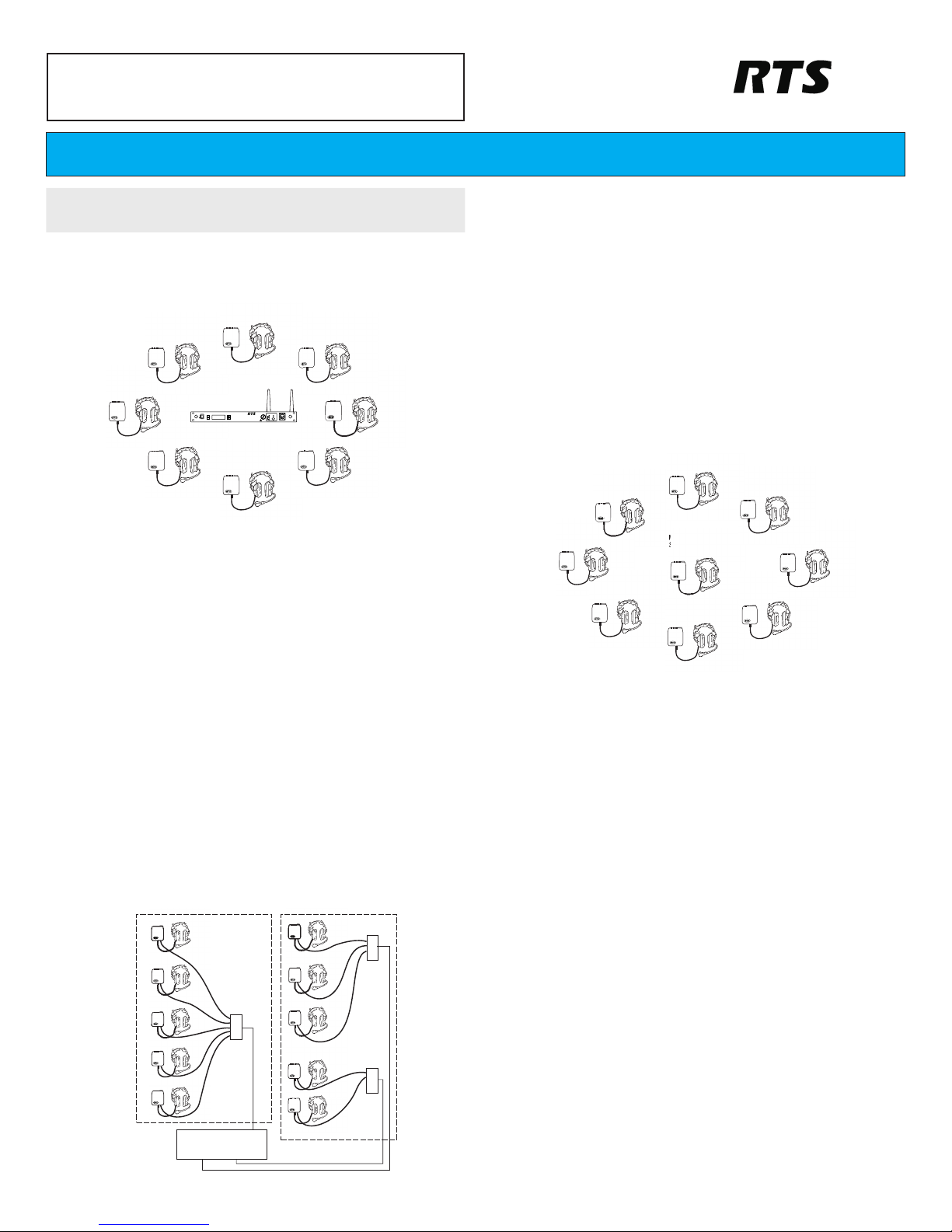
Wireless Mode Setup
For a wireless mode configuration, a BTR-240 base station provides the wireless coverage
area for beltpacks configured in wireless mode.
1. Select a location for the BTR-240 base station and connect the power cord and
antennas.
•
For omni-directional antennas, place the BTR-240 as close to the center of th e coverage
area as possible.
2. Connect the base station to external audio interfaces. For example: local headset,
2-wire, 4-wire, auxiliary, speaker.
3. Turn on the base station.
•
After approx. 25 seconds, the boot cycle will complete and Status Screen is displayed.
•
Activate the connected audio interfaces by navigating the menu on the LCD screen.
4. Perform a ClearScan.
•
Press and hold the <MENU> + <SET> buttons simultaneously for approx. 3 seconds.
•
ClearScan will find and select the optimal RF channel for operation.
5. Plug headsets into the TR-240 beltpacks and turn them on, one by one.
•
If the beltpack has not been previously set to “wireless mode”, press and hold the
<TALK> button while the beltpack boots.
•
Allow a few seconds between each beltpack power on.
•
After approx. 20 seconds, a voice prompt will announce “wireless” in the beltpack
headphones indicating that wireless communication has started.
Wired Mode Setup
For a wired mode configuration, TR-240 beltpacks are directly connected to each other via
Ethernet cable or through a building’s Ethernet infrastructure. No base station is required for a
wired mode configuration.
1. Connect the TR-240(s) to each other with Ethernet cables via the RJ-45
connectors.
•
Use CAT-5e or better Ethernet cables that are wired to standards T-568A or T-568B.
•
Do not use more than 100m (328ft) of Ethernet cable between devices.
•
If desired, a TR-240 in wired mode can be plugged into an AC outlet for prolonged use.
2. Plug headsets into the TR-240 beltpacks and turn them on, one by one.
•
If the beltpack has not been previously set to “wired mode”, press and hold the <2>
button while the beltpack boots.
•
Allow a few seconds between each beltpack power on.
•
After approximately 20 seconds, a voice prompt will announce “wired” in the beltpack
headphones indicating that wireless communication has started.
Master Wireless Mode Setup
For a master wireless mode configuration, one TR-240 beltpack is configured as the “master”
and provides the wireless coverage for other “wireless” beltpacks. The “master” beltpack can
still be used for audio just as a “wireless” beltpack. No base station is required for a master
wireless mode configuration.
1. Select one of the beltpacks to operate in master wireless mode and plug in a
headset.
•
If desired, the “master” beltpack can be plugged into an AC outlet for prolonged use.
2. Turn on the “master” TR-240 beltpack.
•
If the beltpack has not been previously set to master wireless mode, press and hold the
<1> button while the beltpack boots.
•
After approximately 20 seconds, a voice prompt will announce “master wireless” in the
beltpack headphones.
•
A second voice prompt will announce the current RF channel of operation, for example,
“Channel 1”.
3. Perform a ClearScan.
•
Continue holding the <1> button until the voice prompt announce “RF Selection”.
•
Press <TALK> and the voice prompt will announce “ClearScan”.
•
ClearScan will find and select the optimal RF channel for operation.
•
Release all the buttons for approx. 3 seconds and the ClearScan channel becomes
active.
4. Once the “master” TR-240 beltpack has booted and been configured, plug
headsets into the “wireless” beltpacks and turn them on, one by one.
•
If the beltpack has not been previously set to “wireless mode”, press and hold the
<TALK> button while the beltpack boots.
•
Allow a few seconds between each beltpack power on.
•
After approximately 20 seconds, a voice prompt will announce “wireless” in the
beltpack headphones indicating that wireless communication has started.
BTR-240/TR-240
Wireless Intercom F01U196143 Rev 01
NOTE: Prior to use, the BTR-240 battery packs should be fully charged. Refer
to the battery charge instructions in the user manual.
H
U
B
H
U
B
Location
1
Location
2
H
U
B
Building
Infrastructure
Q U I C K S T A R T G U I D E
TALK
CHANNEL
SELECT
11
22
VOLUME
BTR-240
POWER
menumenu
set
AuxOut:1&2GAuxOut:1&2G
AuxIn:1&2LAuxIn:1&2L
RF Ch: 6 2W:1&2RF Ch: 6 2W:1&2
Assoc: 0 4W:1&2Assoc: 0 4W:1&2
MASTER TR-240
SERVING AS A
BASE STATION
Bosch Security Systems, Inc.
TALK
CHANNEL
SELECT
11
22
VOLUME
BTR-240
POWER
menu
set
AuxOut:1&2GAuxOut:1&2G
121
3
4
6
7
5
8 9
10
AuxIn:1&2LAuxIn:1&2L
RF Ch: 6 2W:1&2RF Ch: 6 2W:1&2
Assoc: 0 4W:1&2Assoc: 0 4W:1&2
10
BTR-240
Bosch Security Systems, Inc.
S.N. 00000
MADE IN USA
PROGRAM
10 26
TX
RX
SPEAKER
PUSH
2 WIRE
AUDIO
4 WIRE
INTERCOM 1
L
O
O
P
L
O
O
P
T
H
R
U
T
H
R
U
PUSH
2 WIRE
AUDIO
4 WIRE
INTERCOM 2
L
O
O
P
L
O
O
P
T
H
R
U
T
H
R
U
PUSH
AUXILARY
INPUT
OUTPUT
12/15/VDC
1.5A
12
11
13
14
16
17
15
1
IP: 192.168.1.1
BTR-240
Bosch Security Systems, Inc.
Illlll ll lllll lll lll llllllllllllllll llll lll llll lllll
Illllllll llllll llllllllllllll lllllllllll llll lllllllllll
Illlllllllllll llll llll lll llll lllll lll llllllllll lll
Illlll lllllllllll llll llllll ll llll lll llll lllll
Illlll lll lll ll lllllll
Illlllllll ll lll ll lllll lllllll
AUDIO
918
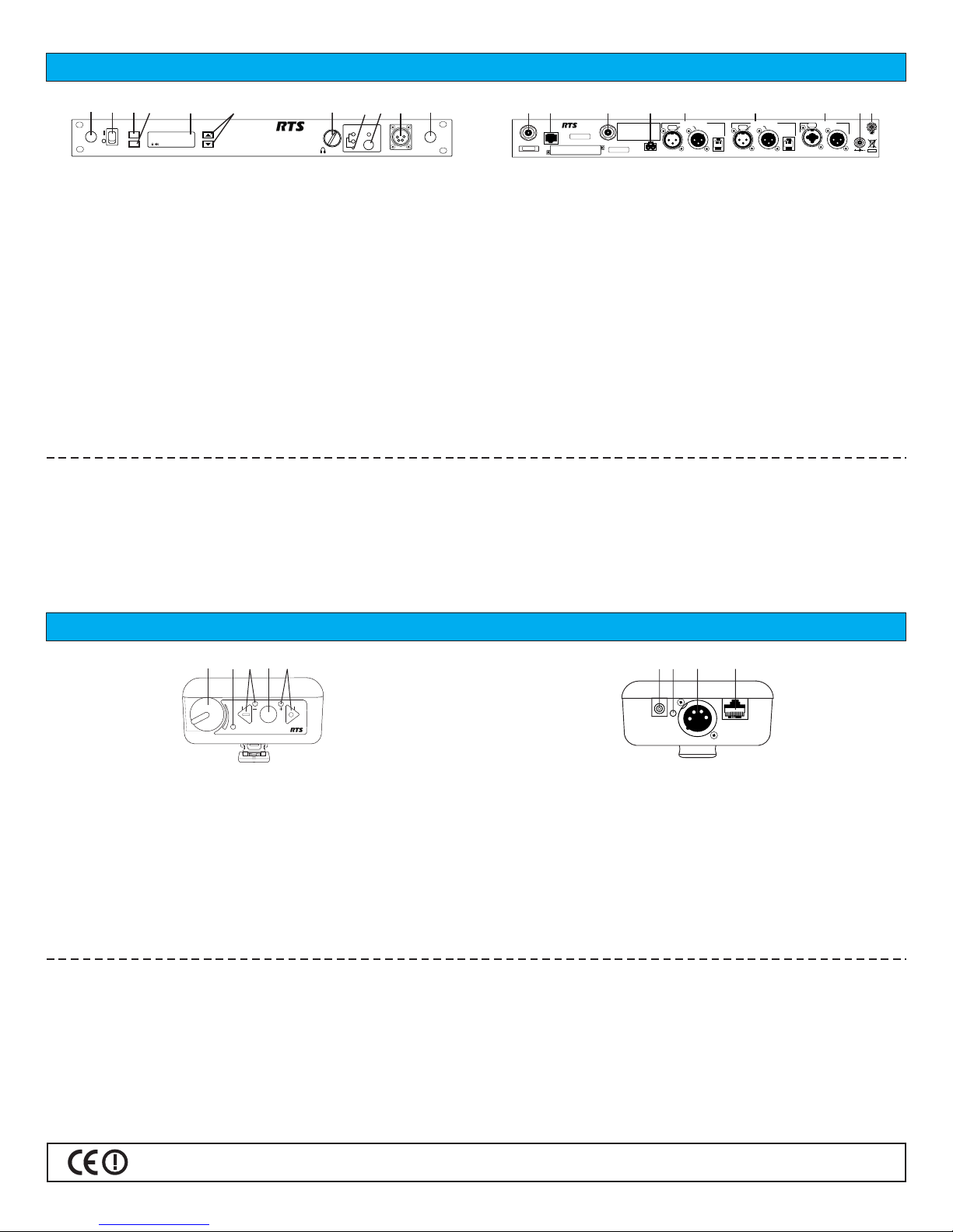
TR-240 Controls and Connections
OFF
ON
BATTERYBATTERY
11
22
MICMIC
ADJADJ
TALKTALK
S.T.S.T.
ADJADJ
TR-240TR-240
2
1
3
4
5
1. On/Off & Volume Control – turns the power on/off and controls the headset volume.
2. Battery Light –
GREEN = Battery OK
YELLOW = Battery Low (approx. 15 mins. left)
RED = Battery Low (battery needs charge)
3. Channel “Green” Button and Light – selects the “Channel 1” intercom. The green
light will illuminate upon selection.
4. <TALK> button – press to enable/disable the audio path from the headset
microphone. Channel LED(s) will illuminate solid when the microphone path is
enabled and will blink when the microphone path is disabled.
5. Channel “Blue” Button and Light – selects the “Channel 2” intercom. The green light
will illuminate upon selection.
6. Charge Jack – used to charge the Li-Ion battery. Accepts 12VDC regulated power
supply.
7. Charge Light –
RED = Battery is charging.
GREEN = Battery is charged.
8. Headset Connector – standard 4-pin XLR connector. Male XLR for Telex units, female
XLR for RTS units.
9. Program Input – RJ-45 jack for wired Ethernet connections.
1. Power on/off switch – turns the power on/off.
2. <MENU> button – used to navigate the menu options on the LCD.
3. <SET> button – used to navigate the menu and select options on the LCD.
4. Backlit Graphics LCD (liquid crystal display)
5. <UP> and <DOWN> buttons – used to navigate the menu options on the LCD.
6. <VOLUME> control knob – controls the volume for the local headset.
7. <CHANNEL SELECT> button – controls the intercom channel to which the local
headset is connected.
8. <TALK> button – press to enable/disable the audio path from the local headset.
LED will illuminate solid when active.
9. Local Headset Connector – standard 4-pin XLR connector. Male XLR for Telex
units, female XLR for RTS units.
10. Antenna Mount Knockout – remove to mount the antennas on the front panel if desired.
BTR-240 Special Key Sequences:
ClearScan <MENU> + <SET> for approx. 3 seconds.
Sequence takes from 25 to 45 seconds to complete.
Lockout <UP> + <DOWN> for approx. 3 seconds.
Repeat to toggle on/off.
Software Version <SET> + <DOWN> for approx. 3 seconds.
Will flash the software version for approx. 3 seconds.
Factory Restore <MENU> + <SET> + <UP> + <DOWN> for approx. 3 seconds.
User reset to restore audio settings and RF channel.
Factory restore to restore audio settings, RF channel, and all
configurations.
OFF
7
6
8
9
TR-240 Special Key Sequences:
Wireless Mode Press and hold <TALK> while booting.
Wired Mode Press and hold <2> while booting.
Master Wireless Mode Press and hold <1> while booting.
Momentary Mode / <1> + <TALK> + <2> for approx. 5 seconds.
Push-to-Latch Mode Repeat to toggle
Microphone Gain <1> + <TALK> for approx. 3 seconds.
Continue to hold <TALK> and us <1> to decrease the gain
and <2> to increase the gain. Release all buttons to set.
Sidetone Level <2> + <TALK> for approx. 3 seconds.
Continue to hold <TALK> and use <1> to decrease the
level and <2> to increase the level. Release all buttons to set.
Software Version <1> + <2> for approx. 5 seconds.
Voice prompts will indicate the mode and software
version.
BTR-240 Controls and Connections
11. Transmit Antenna – reverse "TNC" connector.
12. Program Input – RJ-45 jack for wired Ethernet connections.
13. Receive Antenna – reverse "TNC" connector.
14. Speaker Output – 2-pin connector to attach cables and a speaker.
15. Intercom Channel 1 In/Out – 2-wire and 4-wire interface to wired intercom system 1.
16. Intercom Channel 2 In/Out – 2-wire and 4-wire interface to wired intercom system 2.
17. Auxiliary Input/Output – 3-pin female XLR / ¼" combo jack for input and 3-pin male
XLR output.
18. DC Input Jack – accepts 12-15 VDC, 1.5 Amp source to power the BTR-240.
19. Chassis Ground – grounding point of the base station.
Made in U.S.A. 6/2011
 Loading...