

Page 1
1
I
I(,
,'
L.
i
j'
I
4
,
..*,
RTS
SYSTEMS
PROFESSIONAL INTERCOMMUNICATIONS
PROFESSIONAL AUDIO PROOUCTS
1100 WEST CHESTNUT STREET
BURBANK. CALIFORNIA 91506
PHONE 818f843-7022
TELEX 194855
Series
800
MODEL
Master
Station
l.nterc,om
802
.
-
,.
;
Page 2
NOTICE:
''LJ3rfir..ng:
radio frequency energy and
This equipment generates, uses, and can radiate
if
not installed and used In
accordance with the instructions .manual, may cause
interference to radio communications. It has been tested
and found to comply wi'th the limits For
device pursuant to Subpart
J
of Part
15
a
Class A computing
of
FCC
Rules, which
are designed to provide reasonable protection against such
interference when operated in
a
commercial
environment.
Operation of this equipment in a residential area is likely
to.cause interference in which case the user at his own
may
expense will'be required to take whatever measures
be
required to correct the interference."
Page 3
ADDENDUM TO TECHNICAL DATA PACKAGE
Model 802 Intercom Station
Specifications For
RS232
Operation
The following criteria are established as requirements for the RS232 communications
option for the RTS Systems Model 802.
Operate and interrogate all front panel buttons.
Inhibit operation of front panel buttons.
Determine Status of all DIP switches (byte wide).
Read and modify all programmable (RAM) memory.
Operate all relays, talkllisten gates, key lines independently of button
positions.
Initiate a warm or cold start.
Always send out a code upon operator initiation of warm or cold start.
On command, send out a code upon operator initiation of any function, front
panel or DIP switch change.
RS232 software should never cause the 802 to hang or lock up.
Host computer should have the ability to write and execute machine code in
RAM
for diagnostic or other purposes.
,
~
(\-)
RS232
Lanyuaye Implementation
For RS232 commu~cations, the buttons are numbered from 1 to 48.
1
The physical front panel buttons are numbered
to 32. Certain connectibns to the rear
panel are numbered 33 to 48.
Code Definition
1-12
13-24
Top row of front panel buttons.
Second row of front panel buttons.
25-32 Function buttons, front panel, bottom row.
33 External camera iso input.
34 External global reset tally.
35 External
mic.
37-48 Call light inputs (from phase lock loops).
By treating the external contacts as if they were front panel buttons, the external host
computer can turn them on or off, inhibit the function completely (in either the on or off
position), assign a relay to the function, force a chime signal, et cetera.
RTS Systems, Inc.
Burbank,
CA
91506 / FSCM: 60572 TDP3510
/
Rev.B /January 19891
Copyright 1986,1987,1988,1989 by RTS Systems, Inc. All Rights Reserved.
Page 1 of
4
i
I
Page 4
ADDENDUM TO TECHNICAL DATA PACKAGE
Model 802 Intercom Station
Command Structure
All commands will be initiated by a letter, followed by a numeric modifier, followed by an
operator, followed by a terminating carriage return. The command letter indicates the
major functions such as
BUTTON, KEY, RELAY, MEMORY, et cetera. The numeric
modifier usually refers to which button, or relay or memory is associated with that
(+)
particular command. The operator tells the 802 whether to turn something on
or to inquire about its present state
(?).
or off
Some commands have no modifiers or operators such as WARM START or COLD
START or VERSION.
All commands must be terminated in a carriage return before the 802 will act on them.
Command lines must be limited to 128 characters in length. (Only the load memory
command has the capability of exceeding 'this limit.)
()
Error Handling
The 802 cannot stop when it encounters a confusing a command, it will simply ignore the
entire command. Specific errors include a command letter not in its command table, a
numeric modifier that is out of range (for example, relay
12), and unrecognizable operator,
et cetera. Upon detection of an error, the interpreter will normally ignore the remainder
of a command.
The 802 will send out the letter E along with a 2 digit code indicating where the command
interpreter was confused:
Code Definition
EOO Syntax error.
E01 Output buffer overflow.
E03
E04
El0
Unrecognizable command modifier
Number out of range (for example, illegal button number).
RS232
framing or parity error.
(+
,-,
or ? expected).
E20 RS422 framing or parity error.
RTS Systems, Inc. Burbank, CA 91506 / FSCM: 60572 TDP3510
/
Rev.B /January 19891
Copyright 1986, 1987, 1988, 1989 by RTS Systems, Inc. All Rights Reserved.
Page 2 of
4
Page 5
ADDENDUM
Model
TO
TECHNICAL
802
Intercom
DATA
Station
PACKAGE
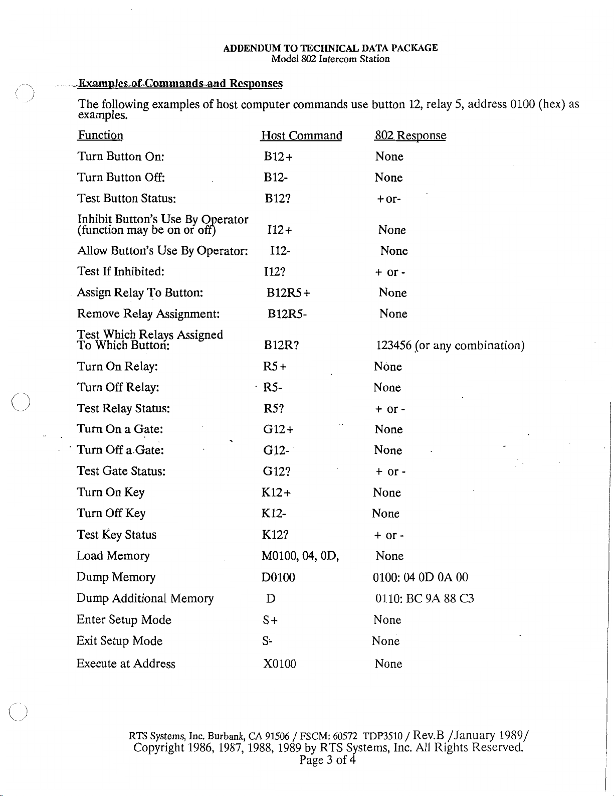
The following examples of host computer commands use button 12, relay 5, address 0100
examples.
Function
Turn Button On:
Turn Button Off:
Test Button Status:
Inhibit Button's Use By
0
erator
(function may be on or off$
Allow Button's Use By Operator:
Test If Inhibited: I12?
Assign Relay To Button: B12R5
Host Command 802 Response
B12+
B 12-
B 12?
I12+
112-
+
None
None
+
or-
None
None
+
or-
None
Remove Relay Assignment: B12R5- None
Test Which Relays Assigned
To Which Button:
Turn On Relay:
Turn Off Relay:
+
R5
R5- None
123456 (or any combination)
None
(hex)
as
Test Relay Status:
R5?
Turn On a Gate: GI2
+
+
or-
None
Turn Off a.Gate: G32- None
Test Gate Status:
Turn On Key
Turn Off Key
Test Key Status
Load Memory
Dump Memory
Dump Additional Memory
Enter Setup Mode
Exit Setup Mode
Execute at Address
G
12?
K12
+
K12-
K12?
M0100,04, OD,
DO100
D
S
t
S.
XOlOO
+
or-
None
None
tor-
None
0100: 04 OD OA 00
0110:
None
None
None
BC
9A 88
C3
RTS Systems, Inc. Burbank, CA
91506
/
FSCM:
60572
TDP3510
Copyright 1986, 1987,1988, 1989 by RTS Systems, Inc.
Page 3 of 4
/
Rev.B /January 1989/
All
Rights Reserved.
Page 6
ADDENDUM TO TECHNICAL DATA PACKAGE
Model
802
Intercom
Station
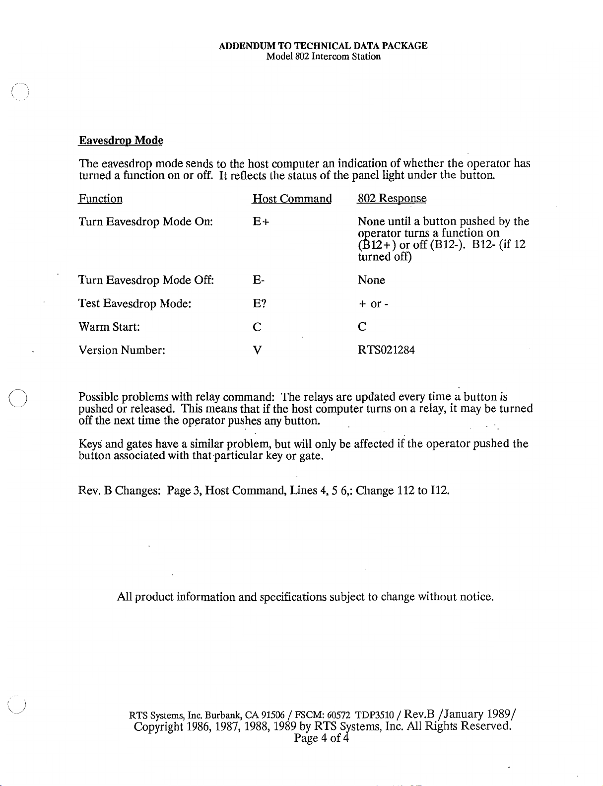
Eavesdro~
Mode
The eavesdrop mode sends to the host computer an indication of whether the operator has
turned a function on or off. It reflects the status of the panel light under the button.
Function Host Command 802 Response
Turn Eavesdrop Mode On: Et
None until a button pushed by the
operator turns a function on
(B12+) or off (B12-). B12- (if 12
turned off)
Turn Eavesdrop Mode Off: E- None
+
Test Eavesdrop Mode: E?
or-
Warm Start: C C
Version Number:
V
RTS02 1284
Possible problems with relay command: The relays are updated every time a button is
on
a
pushed or released. This means that if the host computer turns
relay, it may be turned
off the next time the operator pushes any button.
Keys and gates have a similar problem, but will only be affected if the operator pushed the
button associated with that particular key or gate.
Rev. B Changes: Page
3,
Host Command, Lines 4,5 6,: Change 112 to 112.
All product information and specifications subject to change without notice.
RTS
Systems,
Copyright 1986, 1987, 1988, 1989 by RTS Systems, Inc.
Inc.
Burbank,
CA 91506 / FSCM: 60572 TDP3510
/
Rev.B /January 19891
All
Rights Reserved.
Page 4 of 4
Page 7
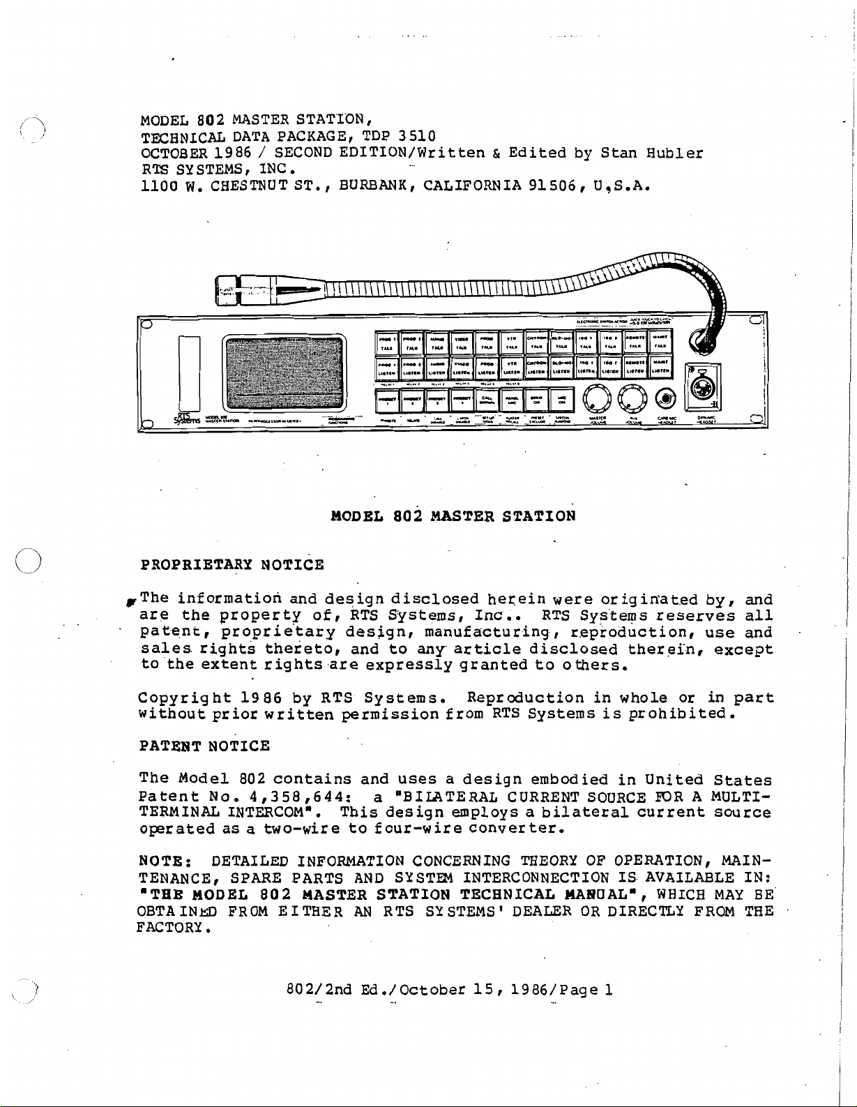
MODEL
TECHNICAL DATA PACKAGE, TDP
OCTOBER 1986
RTS SYSTEMS
1100
802
MASTER STATION
/
I
W.
CHESTNUT ST.
SECOND EDITION/Written
INC
.
BURBANK,
MODEL
3
510
&
Edited by Stan Hubler
CALIFORNIA 91506 U9S.A.
802
MASTER STATION
PROPRIETARY NOTICE
@The informatiori and design disclosed herein
are
the property
patent, propr ie'tary design, manufacturing-, r.eproduction,
sales.
to 'the extent rights
Copyright 1986 by RTS Systems.
without prior written permission from RTS Systems
PATENT NOTICE
The Model 802 contains and
Patent
TERMINAL INTERCOMa. This design employs
operated
NOTE: DETAILED INFORMATION CONCERNING THEORY OF OPERATION
TENANCE , SPARE PARTS
'THE MODEL
OBTA
FACTORY.
rights thereto, and
No.
4,358,644:
as
a
two-wire
802
INm
FROM E I TEER
of,
RTS Systems, Inc.. RTS Sys'te~?s reserves
to
any'
article
.are
expressly granted to others.
Reproduction in whole or in part
uses
a
"BIIATERAL CURRENTSOURCE
to
four-wire converter.
AND
SYSTEM INTERCONNECTION IS AVAILABLE
MASTER STATION TECHNICAL
AN
RTS SYSTEMS' DEALER
a
design embodied in United States
were
disclosed thereibr except
a
bilateral current source
origin'at.ed by, and
is
prohibited.
EDRA
14A10UALn,
OR
DIRECTLY FROM THE
use
MULTI-
,
WHICH
all
and
MAIN-
IN:
MAY
BE
Page 8
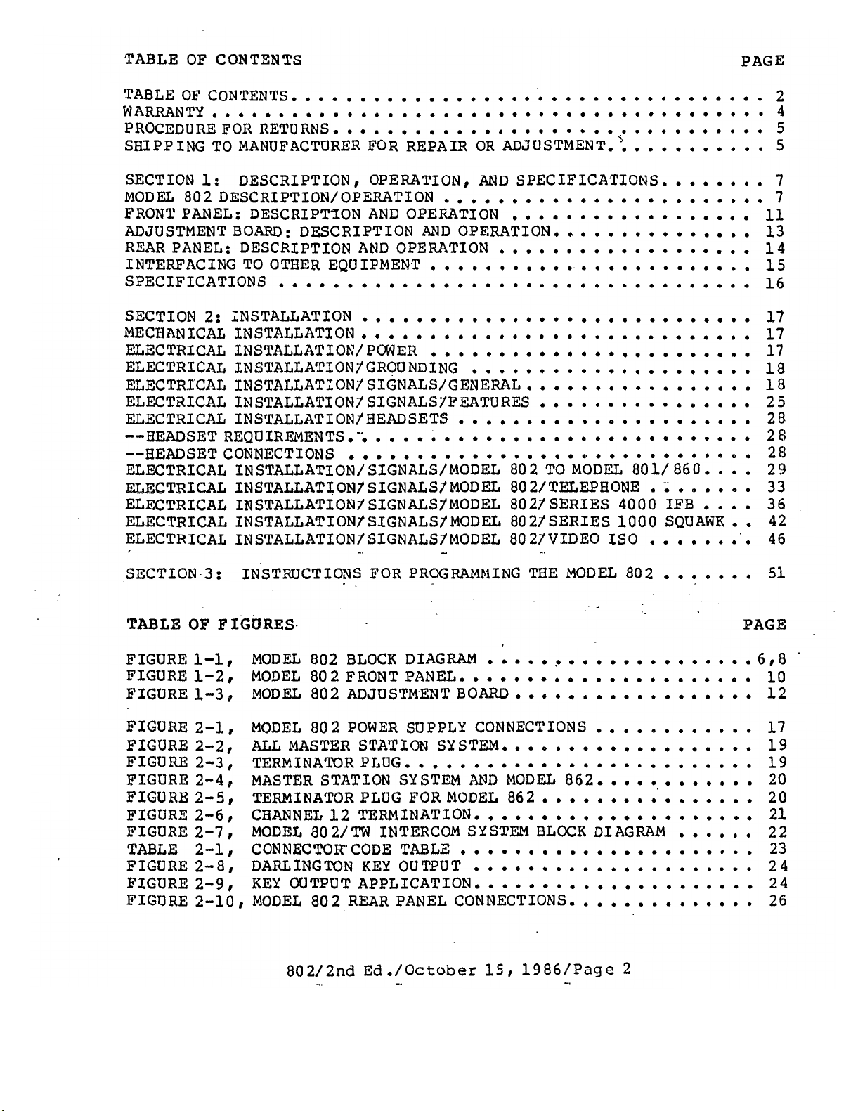
TABLE OF CONTENTS PAGE
TABLEOFCONTENTS
WAREiANTY
PROCEDUREFORRETURNS
SEIPPING TO MANUFACTURER FOR REPAIR OR ADJUSTMENT
SECTION
MODEL 802 DESCRIPTION/OPERATION
FRONT PANEL: DESCRIPTSON
ADJUSTMENT BOARD: DESCRIPTION AND OPERATION
REAR PANEL: DESCRIPTION
INTERFACING TO OTHER EQUIPMENT 15
SPECIFICATIONS
SECTION 2: INSTALLATION
MECHANICAL INSTALLATION 17
EI;ECTRICAL INSTALLATION/POCIJER 17
ELECTRICAL
ELECTRICAL INSTALLATION1 S JGNALS/GENERAL 18
ELECTRICAL
ELECTRICAL INSTALLATIONf HEADSETS 28
..HEADSET REQUIREMENTS... 28
..HEADSET CONNECTIONS 2fJ
ELECTRICAL INSTALLATION/ SIGNALS/MODEL 80 2 TQ MODEL
ELECTRICAL
ELECTRICAL
ELECTRICAL
ELECTRICAL
..........e...............m*****.*..**.**
DESCRIPTION.
1:
INSTALLATION/GROUNDING
INSTALLATION1SIGNALSlFEATURES
INSTALLATIONlSIGNALSfMODEL
IMSTRLLATIONISIGNALSlMODEL
INSTALLATIONlSIGNALS1MODEL
INSTALLATIONlSIGNALSlMODEL
....................................
................................
OPERATION. AND SPECIFICATIONS
5
............
........................
AND
OPERATION
.
.
. .
...............
AND
OPERATION
.
.
........................
...................................
. . . .
.
. . .
.
.
.............................
........................
. .
.................
................
......................
............................
..............................
802/TEZEPHONE
8021SERIES 4000 IFB
8021 SERIES 1000 SQUAWK
.
.
.
8021VIDEO IS0 46
.
801/ 860
.
. .
....
.
......
i
....
.
........
.
2
4
5
5
7
7
11
13
14
16
17
18
25
29
33
36
42
SECTION-3:
TABLE
FIGURE
FIGUREl.2. MODEL 802FRONTPANEL
FIGURE 1.3. MODEL 802 ADJUSTMENT BOARD 12
FIGURE 2.1, MODEL 80 2 POWER SUPPLY CONNECTIONS 17
FIGURE 2.2, ALL MASTER STATION SYSTEM
FIGURE2.3, TZRMINATORPLUG
FIGURE 2.4. MASTER STATLON SYSTEM AND MODEL 862 20
FIGURE2.5. TERMINATORPLUGFORMODEL 862
FIGURE2.6. CBANNEL12TERMINATION
FIGURE 2.7. MODEL 80 2/TW INTERCOM SYSTM BLOCK DIAGRAM
TABLE 2.1. CONNECTOR CODE TABLE 23
FIGURE2-8!
FIGURE2.9. KEY OUTPUTAPPLICATION
FIGURE
OF
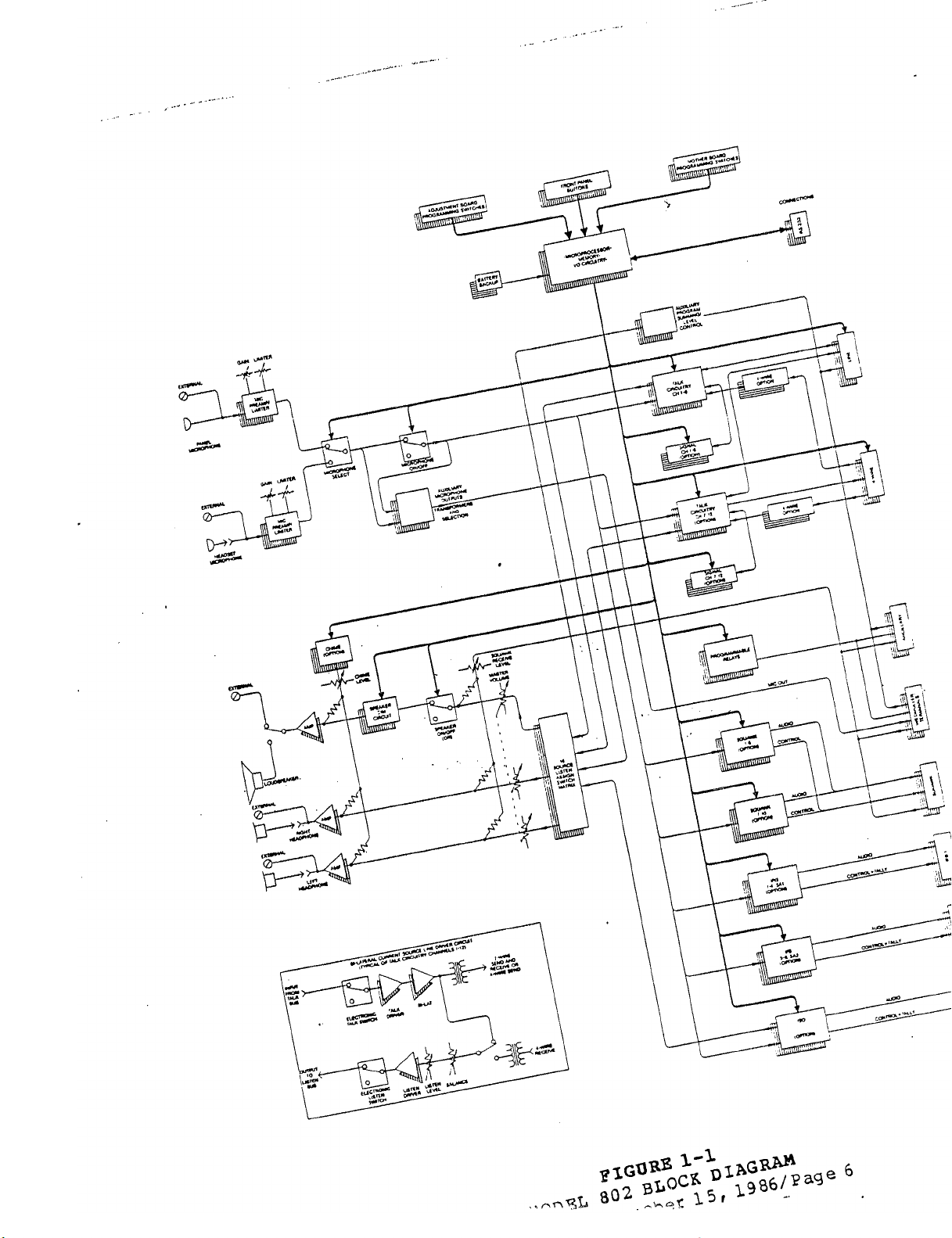
1-1,
2.10.
INSTRUCTIONS
FIGURES
MODEL 802 BLOCK DIAGRAM
.
FOR PROGRAMMING THE MODEL 802 51
......*..............
......................
e.........................
.....................
......................
DARLINGTON KEY OUTPUT
.....................
MODEL 802 REAR PANEL CONNECTIONS
.
.
..................
............
...................
............
...............*
..
0.
l
. .
. . .
..............
.......
PAGE
......
.
6.
10
19
19
20
21
22
24
24
26
8
.
Page 9
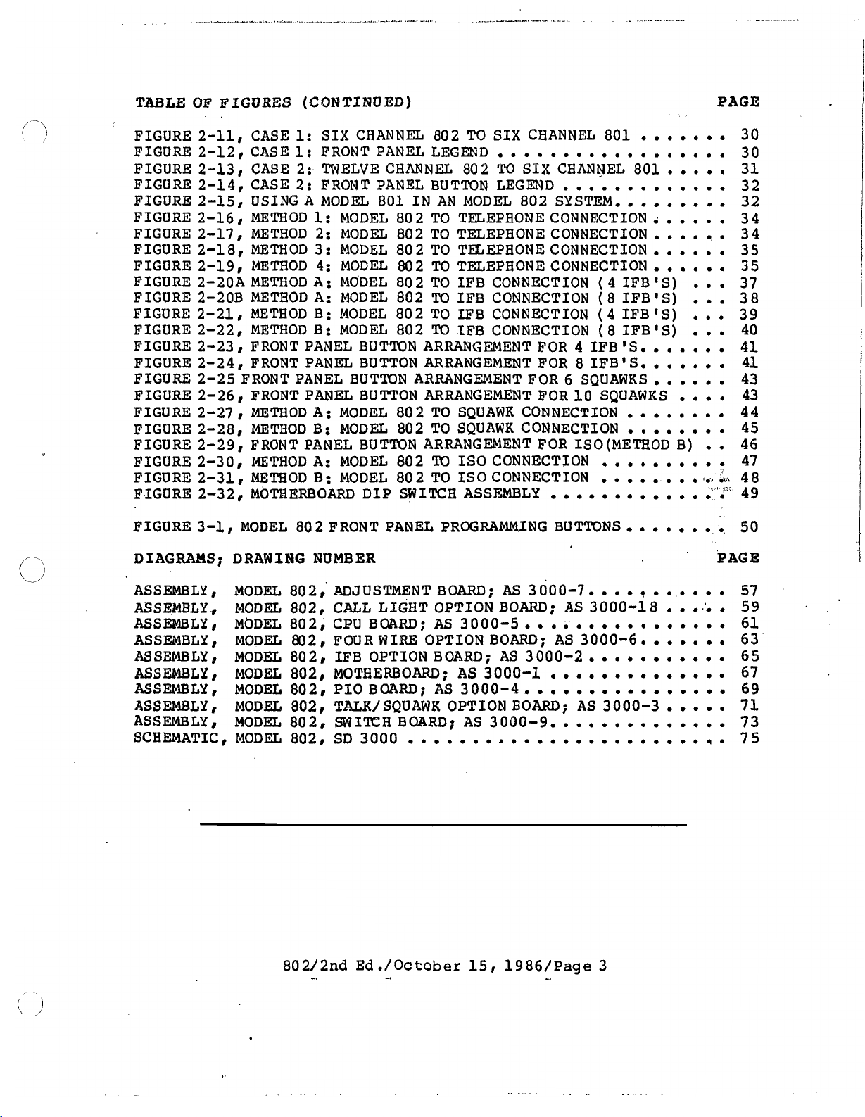
TABLE OF FIGURES (CONTINUED)
PAGE
FIGURE
FIGURE
FIGURE
FIGURE
FIGURE
FIGURE
FIGURE
FIGURE
FIGURE
FIGURE
FIGURE
FIGURE
FIGURE
FIGURE
FIGURE
FIGURE
FIGURE
FIGURE
FIGURE
FIGURE
FIGURE
FIGURE
FIGURE
FIGURE
2-11,
2-12,
2-13
2-14,
2-15,
2-16,
2-17
2-18,
2-19,
2-20A
2-20B
2-21
2-22
2-23
2-24
2-25
2-26
2-27
2-28,
2-29,
2-30,
2-31
2-32,
3-1,
CASE
CASE
,
CASE
CASE
USING A MODEL
METHOD
,
METHOD
METHOD
METBOD
METHOD A : MODEL
METHOD A: MODEL
,
METHOD B: MODEL
,
METHOD B: MODEL
1
FRONT PANEL BUTTON ARRANGEMENT FOR 4 IFB
,
FRONT PANEL BUTTON ARRANGEMENT FOR 8 IFB'
FRONT PANEL BUTTON ARRANGEMENT FOR 6 SQUAWKS
1
FRONT PANEL BUTTON ARRANGEMENT FOR
,
METHOD A: MODEL
METHOD B: MODEL
FRONT PANEL BUTTON ARRANGEMENT FOR ISO(METB0D B)
METHOD A: MODEL
,
METHOD B: MODEL
MO!CEERBOARD DIP SWITCH ASSFBLY
MODEL
1:
SIX CHANNEL
1:
FRONT PANEL LEGEND
2:
TWELVE CHANNEL
2:
FRONT PANEL BUTTON LEGEND
801
1:
MODEL
2:
MODEL
3:
MODEL
4:
MODEL
80 2
FRONT PANEL PROGRAMMING BUTTONS
802
TO SIX CHANNEL
.
. . . .
882
cl'g
SIX
CBANYEE
IN AN MODEL
802
TO TELEPHONE CONNECTION.
802
TO TELEPHONE CONNECTION
802
TO TELEPHONE CONNECTION
80 2
TO TELEPHONE CONNECTION
80 2
TO IFB CONNECTION
802
TO
IFB CONNECTION
802
TO IFB CONNECTION
802
TO IFB CONNECTION
802
TO SQUAWK CONNECTION
802
TO SQUAWK CONNECTION
802
TO
IS0
802
TO
IS0
802
SYSTEM.,
CONNECTION
CONNECTION
801
. . . . . .
. . . . . . . . .
801
.
.
. .
. . . .
. , .
. . . . .
.
.
(
4
IFB ' S)
(
8
IFB 'S)
(4
IFB 'S)
(
8
IFB 'S)
'S.
S.
.
10
SQUAWKS
.
.
.
.
,
.
. . .
.
.
.
. . .
. . . . .
.
.
. .
. . .
.
.
.
. . . .
. . . .
. .
. .
.
. . .
.
.
.
.
.
. .
.
.
.
+.+
O~TC
.
. . .
. .
30
30
31
32
32
34
34
35
3 5
37
3 8
39
40
41
41
43
43
44
45
46
47
48
49
50
DIAGRAMS; DRAWING NUMBER
ASSEMBLY
ASSEMBLY,
ASSEMBLY
ASSEMBLY
ASSEMBLY
ASSEMBLY,
ASSEMBLY,
ASSEMBLY,
ASSEMBLY
SCBEMATIC
8
MODEL
MODEL
,
MODEL
MODEL
,
,
MODEL
MODEL
MODEL
MOD&
p
MODEL
,
MODEL802,
802,
802,
802,
802,
802,
802,
802,
802,
802,
ADJUSTMENTBOARD; AS
CALL LIGHT OPTIONBOARD; AS
CPUBOARD;
FOURWIRE OPTION BOARD; AS
IE'B OPTIONBOARD; AS
MOTHERBOARD;
PIOBOARD; AS
TALK/SQUAWK OPTION BOARD; AS
SWITCH BOARD; AS
SD3000
3000-7.
AS3OOO-5..
AS
3000-1
3000-4o.o
3000-9..
....o.o..........m..o..q.
00......
3000-2.
.
.
..o..o.o.
3000-18
3000-6..
. . .
.
.
3000-3
'
PAGE
.
e'o
...o.
.
.
.
. .
.
.
. . . . . .
.
0.
.
57
59
61
63
65
67
69
71
73
75
Page 10
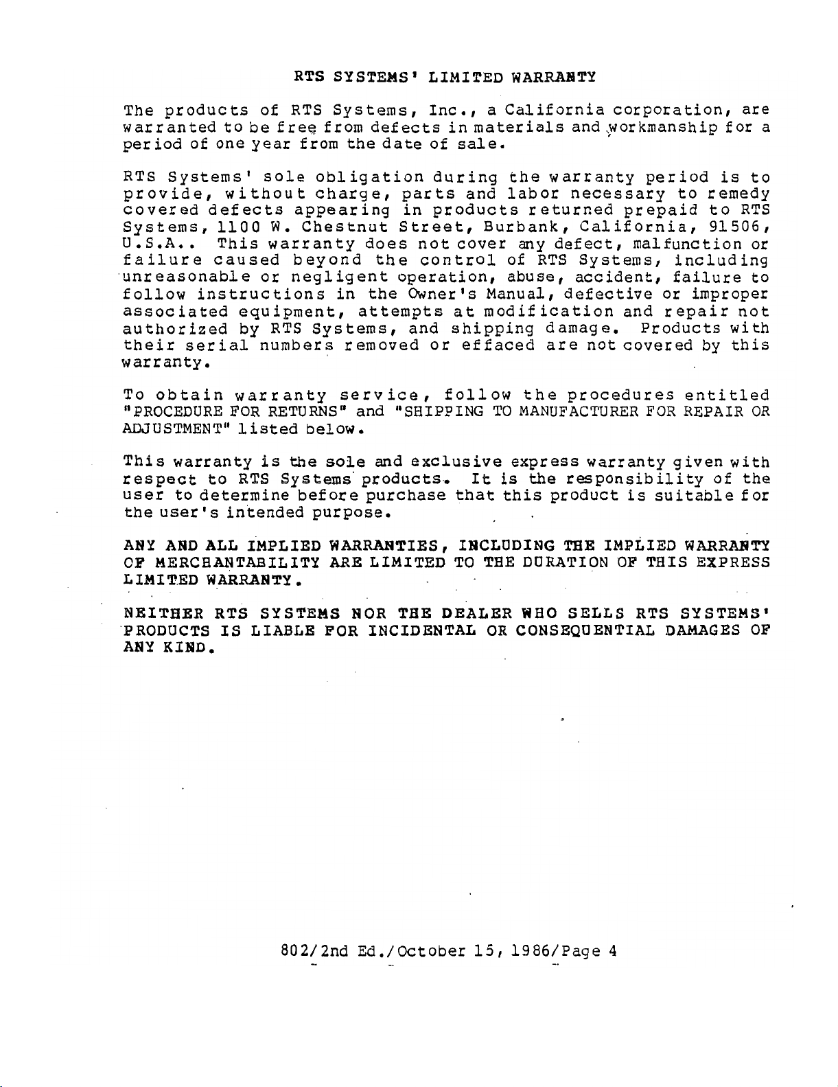
RTS SYSTEMS' LIMITED WARRAHTY
The products of RTS Systems,
Inc., a California corporation, are
warranted to be free from defects in materials and ;workmanship for a
period of one year from the date of
RTS Systemst sole obligation during the warranty period
sale.
is
to
provide, without charge, parts and labor necessary to remedy
covered defects appearing in products returned prepaid to RTS
Systems
1100
We
Chestnut Street, Burbank , Calif ornia, 91506
I
U.S.A.. This warranty does not cover any defect, malfunction or
failure caused beyond the control of RTS Systems, including
unreasonable or negligent operation, abuse accident, failure to
follow instructions in the Owner's Manual, defective or improper
associated equipment,
attempts at modification and repair not
authorized by RTS Systems, and shipping damage. Products with
their
serial
numbers removed or effaced are not covered by this
warranty.
,
To obtain warranty service
"PROCEDURE FOR RETURNSn and "SHIPPING
follow the procedures entitled
TO
MANUFACTURER FOR REPAIR
OR
ADJUSTMENT" listed below.
This warranty
respect to
user to determine before purchase that this product
is
RTS
the
sole and exclusive express warranty given with
Systems' products,
It
is
the
responsibility of the
is
suitable for
the user intended purpose.
ANY
OF
L
AND
ALL
IMPLIED
MERCHANTABILITY
IM I T.ED W ARRABTY
WARRANTIES I IHCLUDING
ARE
.
NEITHER RTS SYSlfEMS
PRODUCTS
ANY
KXID.
IS
LIABLE FOR PNCIDENTAL
THE
IMPLIED
WARRATITY
LIMITED TO TEE DURATION OF THIS EXPRESS
NOR
TBB:
DEALER
OR
WHO
SELLS
RTS
SYSTEMS'
CONSEQUENTIAL DAMAGES OF
Page 11
3
,
,>,,
,,.
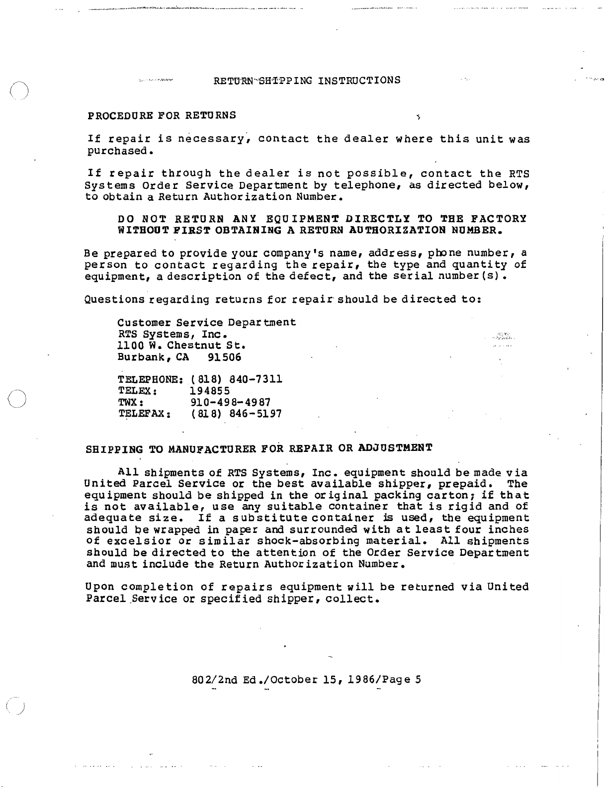
RETU'RF4'.Slil:T'PPING INSTRUCTIONS
PROCEDURE FOR RETURNS
If repair
is
necessary; contact the dealer where this unit was
s
purchased.
If repair through the dealer
Sys
tems
to obtain
Be
prepared to provide your company's name, address, pbne number, a
Order Service Department by telephone, as directed below,
a
Return Authorization Number.
DO
NOT RETURN
W
ITEOOT FIRST
ANY
OBTAINING
EQUIPMENT DIRECTLY TO TEE FACTORY
person to contact regarding
equipment, a description of the defect, and the serial number
is
not possible, contact the RTS
A
RETURN AUTHORIZATION NUMBER,
the
repair, the type and quantity of
(s)
Questions regarding returns for repair, should be directed to:
Customer Service Department
RTS Systems, Inc.
1100
Burbank,
TELEPHONE:
TELEX
TWX:
TELEFAX
W.
Chestnut St.
CA
(
818) 840-7311
:
194855
910-498-4987
:
(
81 8) 846- 51 97
91506
.
SHIPPING TO MANUFACTURER
All
shipments of RTS Systems, Inc. equipment should be made via
REPAIR
OR
ADJUSTMENT
FOR
United Parcel Service or the best available shipper, prepaid. The
equipment should be shipped in the original packing carton; if that
is
not available, use any suitable container that
adequate size. If
should be wrapped in paper and surrounded with
a
substitute container
is
at
of excelsior or similar shock-absorbing material.
is
rigid and of
used, the equipment
least four inches
All
shipments
should be directed to the attention of the Order Service Department
and must include the Return Authorization Number.
Upon completion of repairs equipment
will
be returned via United
Parcel .Service or specified shipper, collect.
Page 12
Page 13
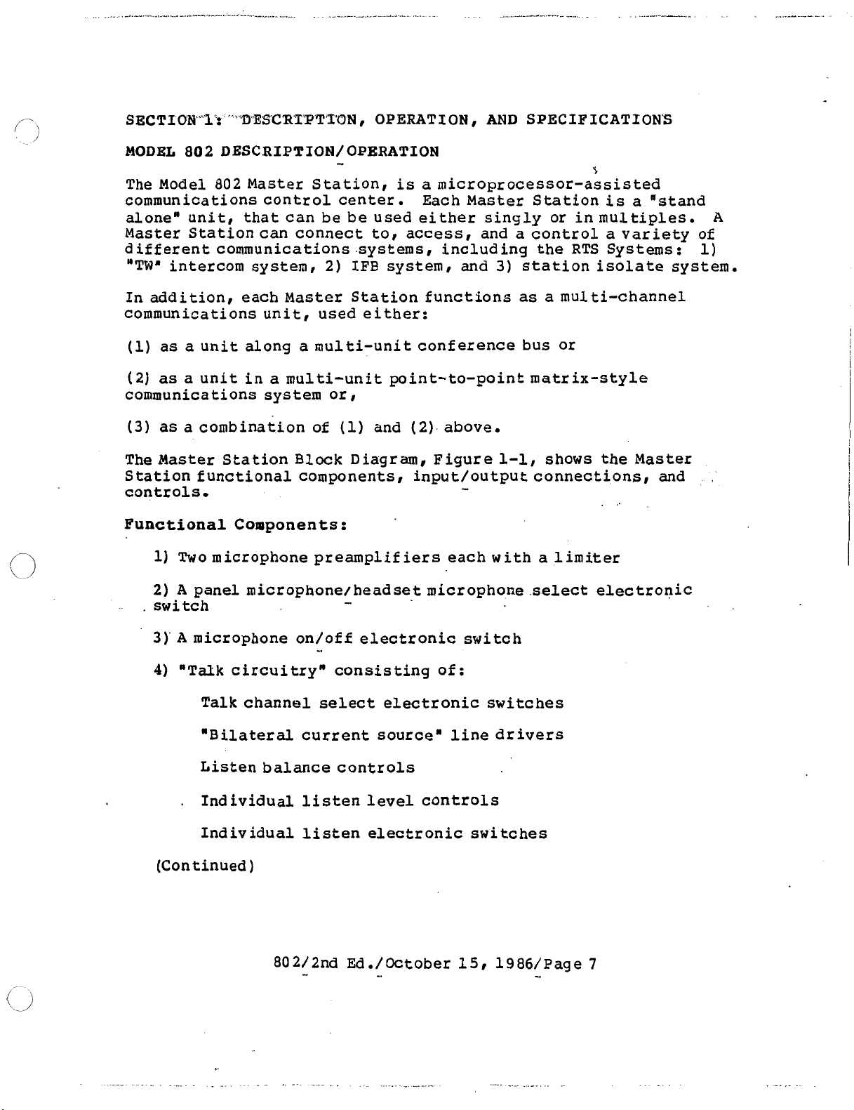
SECTION"1: " "DESC'RXPTTON , OPERATION
,
AND
SPECIFICATION'S
MODEL 802 DESCRIPTION/ OPERATION
The Model 802 Master Station,
communications control center.
alone" unit, that can be be used either singly or in multiples.
Master Station can connect to, access, and a control a variety of
different communications .systems, including the RTS Systems:
"TWa
In addition, each Master Station functions as a multi-channel
communications unit
communications system or,
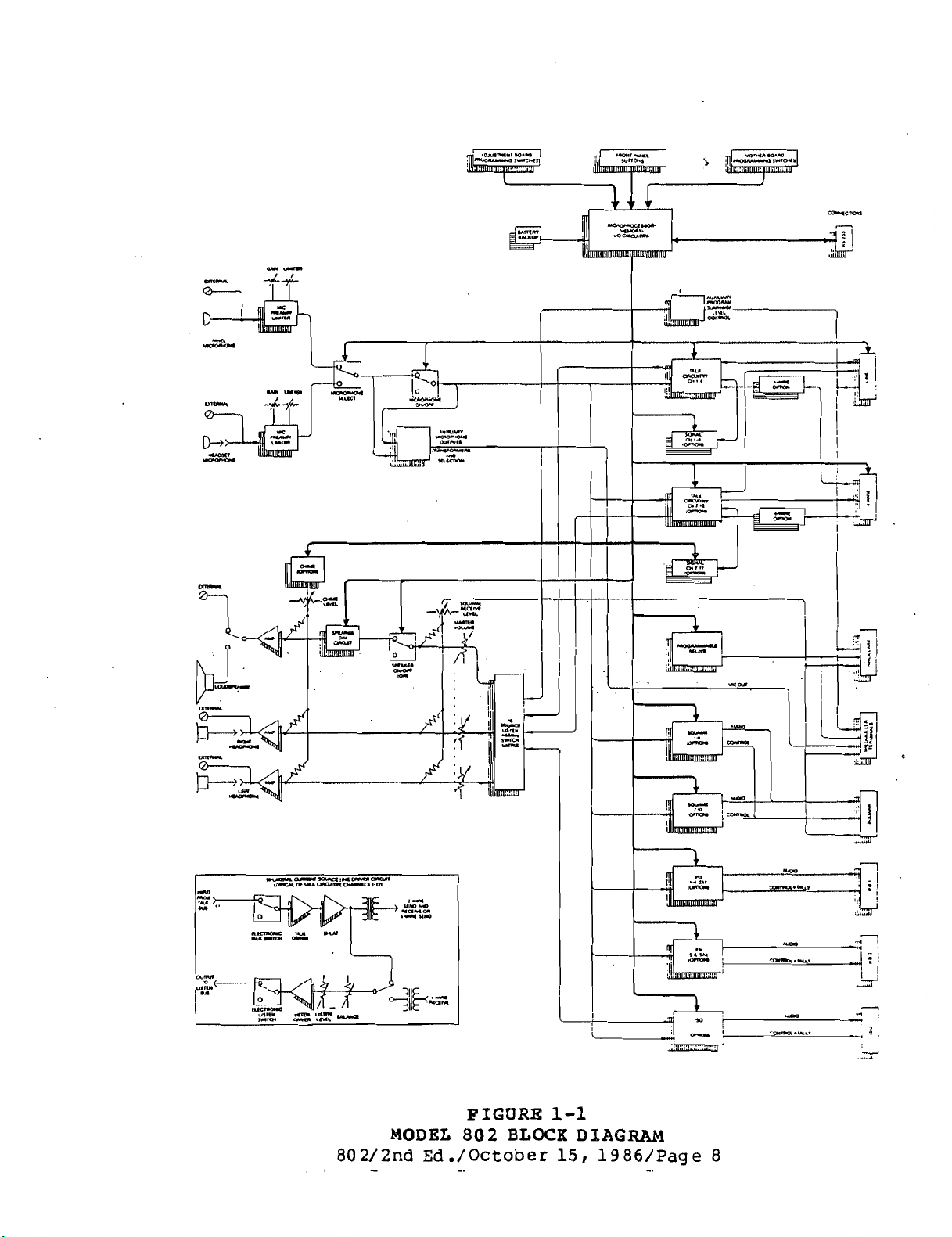
The
Station functional components, input/output connections, and
controls.
Functional Components:
intercom system, 2) IFB system, and 3) station isolate system.
(1)
as a unit along a multi-unit conference bus or
(2)
as
a unit in a multi-unit point-to-point matrix-style
(3) as a combination of
Master
1)
Two microphone preamplifiers each with a
Station Block Diagram, Figure
,
used
-
is
either:
(1)
and (2) above.
s
a microprocessor-assisted
Each
Master
1-1,
Station
shows the
is
a "stand
Master
-
.
..
limiter
1)
A
,
2)
A
panel microphone/headset microphone
.
switch
3)' A microphone on/of f electronic switch
4)
"Talk
.
(Continued)
circuitryn consisting of:
Talk channel
"Bilateral current source" line drivers
Listen balance controls
Individual listen level controls
Individual listen electronic switches
-
-.
select
electronic switches
select
electronic
Page 14
,.
"1
.,i
I.!
-
t----"
rm
-.-.
i
"4
ill
MODEL
802/2nd
-
FIGURE
802
BLOCK
Ed./October
-.
1-1
DIAGRAM
15,
1986/Page 8
-.
Page 15
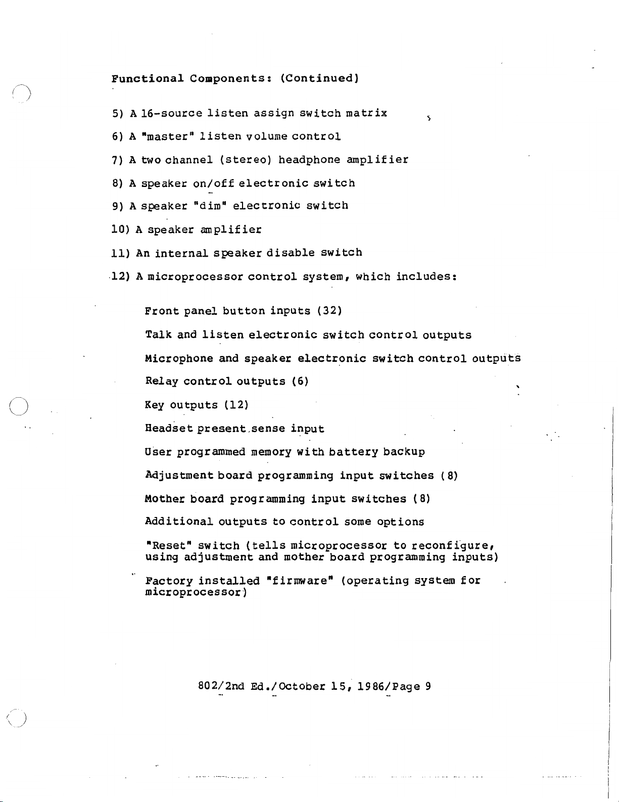
Functional Components: (Continued)
5)
A
16-source listen assign switch matrix
6)
A
"master" listen volume control
7) A two channel (stereo) headphone amplifier
8)
A
speaker on/of f electronic
switch
9) A speaker "dimo electronic switch
10)
A
speaker amplifier
11)
An internal speaker disable switch
A
.12)
microprocessor control system, which includes:
s
Front panel button inputs
Talk
and listen electronic switch control outputs
(32)
Microphone and speaker electronic switch control outputs
Relay control outputs
(6)
Key outputs (12)
~eadset present ,sense input
User
Adjustment board programming input switches
Mother board programming input switches
programmed memory with battery backup
(8)
(
8)
Additional outputs to control some options
"Resetn switch
(tells
microprocessor to reconfi'gurer
using adjustment and mother board programming inputs)
'
Factory installed "firmware" (operating system for
microprocessor^
.
Page 16
t
t-'
m
9
t-'
U3
a3
cn
\
'd
P,
a
cD
t-
o
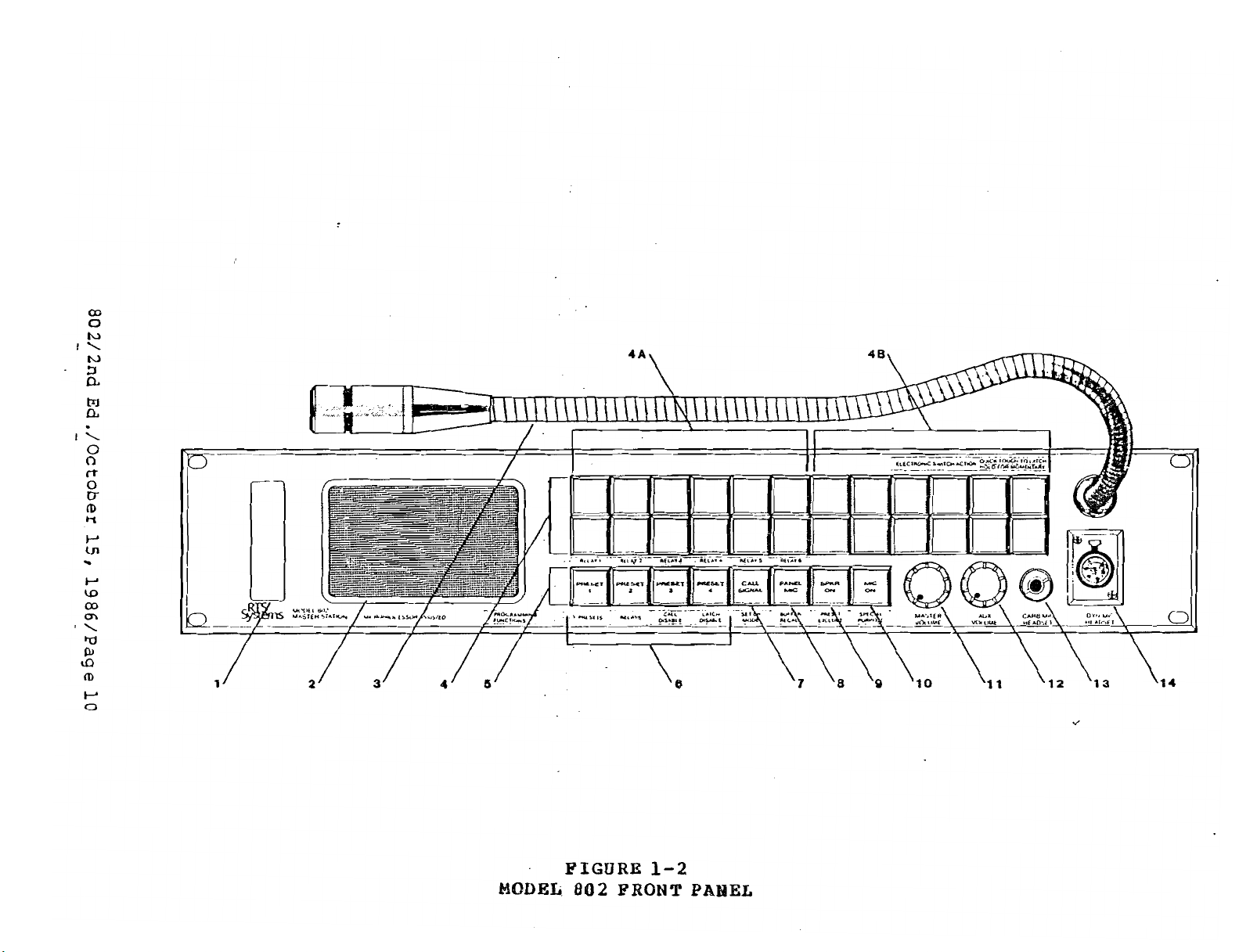
MODEL
FIGURE
802
1-2
FRONT
PANEL
Page 17

0
FRONT
The
buttons
PANEL:
front panel contains
(S),
DESCRIPTION
master {ll) and auxiliary (12) volume ,controls, loud-
AND
BIPERATPON
24
selector buttons
(See
(
41,
Figure
1-2.)
eight opera tion
speaker (21, gooseneck microphone (31, dynamic (141 and carbon (13)
microphone headset connectors, and access to the adjustment board
(1).
(5)
The selection (4) and operation
tions when
Model 802
is
switched from the standard, "operatingn
the
mode to the "programming" mode. Legends under each button show
"programming " function.
See Section
buttons have different f unc-
3
for programming
its
instructions.
In
the
basic Model 802, the
f
irst
twelve selection buttons
(4A)
ac-
tivate the talk circuits (top buttons), and listen circuits (bottom
buttons) of intercom channels
1
through
The remaining twelve
6.
selection buttons (4B) become operational with the addition of op-
tions. Normally, the eight operation buttons
PRESET
the
cuits. The CALL SIGNAL button
when the unit
enable button
1
through PRESET
4
{6)
can be user-programmed to activate, by
push of a single button, combinations of audio and control
(7)
enables the signalling function,
is
equipped with this option.
{8)
selects
the rront panel gooseneck microphone and
deactivates the headset microphone; if no headset
is
PANEL MICrophone only
button
cuit
{9)
turns on the loudspeaker.
is
always on.
The MICrophone
automatically selected. The SPeaKeR
Note: the headset listen
(224
button (10) turns on the
(5)
work
as
follows:
cir-
The PANEL MICrophone
is
plugged in,
ON
cir-
microphone in use (headset or panel).
Most of
ing dual-action: if a button
"latch", (turning 'on" if off, turning "offn if on); if the button
I
is
held slightly longer, the action
tion
ing' function can be disabled.
THE MASTER
io sources going to
the
will
turn off when the button
VOLUME
front panel buttons- feature a special momentary / latch-
is
pressed quickly, the f unctio-n
will
is
be momentary and the f unc-
released.
(Note: This "latch-
See Section 3 for details)
{ll) control
the
left and right side of the stereo headphone
sets
the level of the sum of all aud-
and loudspeaker (exceptions: chime and squawk receive levels)
The Auxiliary VOLUME {12) control
iary program audio inputs (and sends
trol)
,
sets
the
level of the two auxil-
it
to the MASTER
VOLUME
The CARBon MICrophone HEADSET jack (13) accepts a standard 3-con-
ductor
11
4'
phone plug.
d he
necessary
DC
excitation voltage
vided to-power carbon microphones or their electronic equivalent.
The
DYNamic
MICrophone HEADSET (14) connector accepts a stereo
earphone, dynamic microphone headset.
will
,
.
con-
is
pro-
Page 18
Page 19
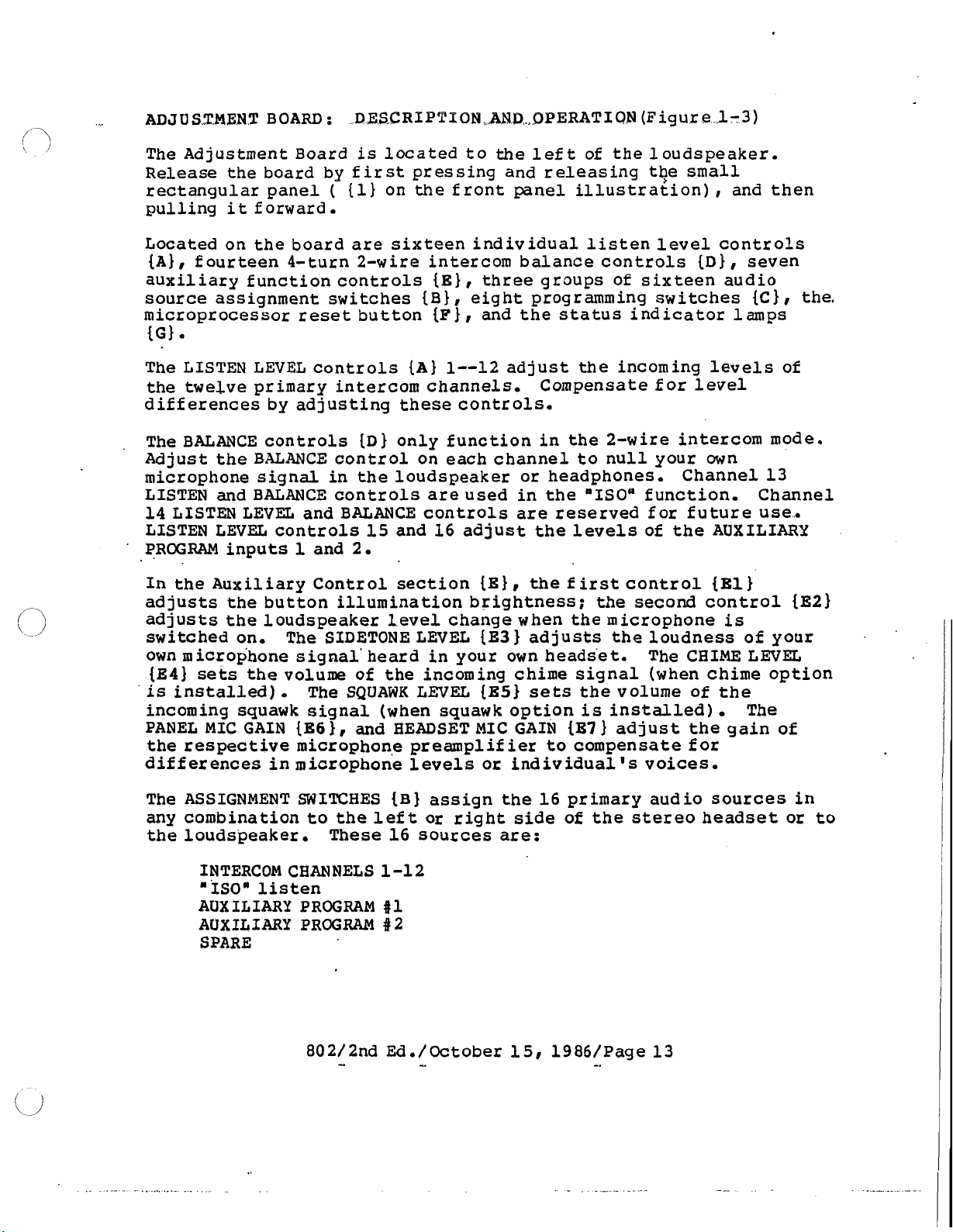
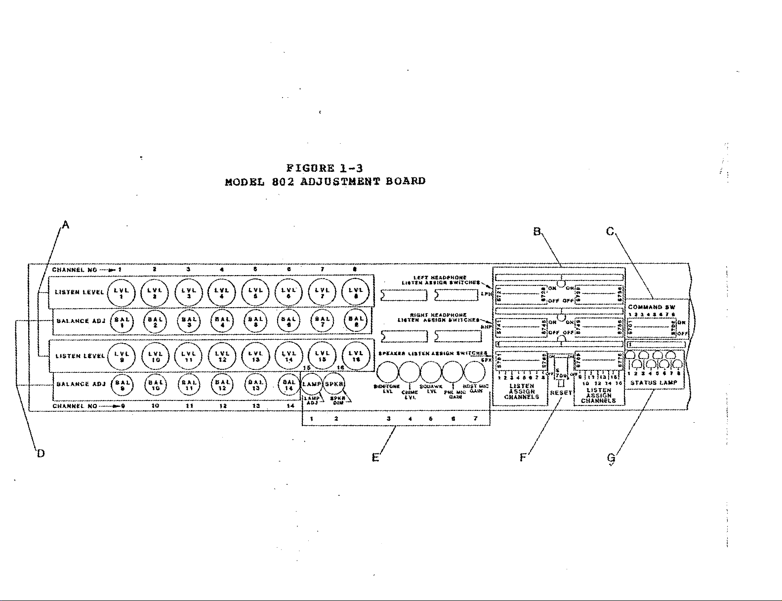
ADJUSTMENT
The
Adjustment Board
Release
rectangular panel
pulling
Located on the board are sixteen individual listen level controls
{A}, fourteen 4-turn 2-wire intercom balance controls {D)
auxiliary function controls {E), three groups of sixteen audio
source assignment switches
microprocessor
{GI
BOARD
the board by fir
it
forward.
reset
DESCRITPTPBN,AHD,..OPERATIC)N
:
is
located to the left of the loudspeaker.
st
pressing and releasing t$e small
(
{I) on the front panel illustration)
{B) , eight programming switches
button {F) , and the status indicator lamps
(Figure ,1-3)
and then
,
,
seven
{c)
I
the.
The LISTEN
the
twelve primary intercom channels.
differences by adjusting these controls.
BALANCE
The
Adjust the BALANCE control on each channel to null your own
microphone signal in the loudspeaker or headphones.
LISTEN and BALANCE controls
14 LISTEN LEVEL and BALANCE controls
LISTEN LEVEL controls 15 and 16 adjust the levels of the AUXILIARY
PROGRAM inputs
In the Auxiliary Control section {E)
adjusts the button illumination brightness; the second control {E2)
adjusts the loudspeaker level change when the microphone
switched on. The SIDETONE LEVEL {E3) adjusts the loudness of your
own microphone signal' heard in your own headset.
{E4)
is
incoming squawk signal (when squawk option
PANEL
the respective microphone preamplifier to compensate for
differences inmicrophone levels or individual's voices.
The ASSIGNMENT SWITCBES
any combination to the left or right side of the stereo headset or
the loudspeaker.
sets
installed)
MIC
LEVEL
controls {D) only function in the 2-wire intercom mode.
controls
1
and 2.
{A}
1-12 adjust the incoming levels of
Compensate for level
Channel 13
are
used in the 'ISOa function. Channel
are
reserved for future use.
,
the f
irst
control
{El)
is
CHIME
The
the volume of the incoming chime signal (when chime option
.
GAIN
The SQUAWK LEVEL
{E6), and HEADSET MIC
{B)
assign the 16 primary audio sources in
These 16 sources are:
{E5)
sets
GAIN
the volume of the
is
installed).
{87}
adjust the gain of
LEVEL
The
to
INTERCOM CBANNELS 1-12
"ISO"
AUXILIARY PROGRAM
AUXILIARY PROGRAM
SPARE
listen
#1
#
2
Page 20

The RESET button
{P}
is
used to
reset
the micsoprocessor.
This
required when initially installing certain options or making
certain programming changes on the Mother Board.
{G}
are used for diagnostic purposes.
The
PROGRAMMING
operating modes. See Figure 2-32A on page
switches
{C}
are used to
set
up various special
44
for illustration.
The STATUS LAMPS
?
is
REAR
PANEL:
The Model 802
DESCRIPTION
is
connected to other Model 802'~~ other systems,
AND
OPERATION
(See Figure 2-10)
external equipment using the connections on the Rear Panel.
The
LINE
terminal strips
The
optional
are
instal1,ed only
{2)
connector,
IFB
ANCILLARY
are
present on a basic Model 802.
{4),
SQUAWK
as
a
part of the various options.
{S}
{3)
I
4-WIRE
connector I and
{6},
and
IS0
18)
screw
17)
connectors
and
Page 21
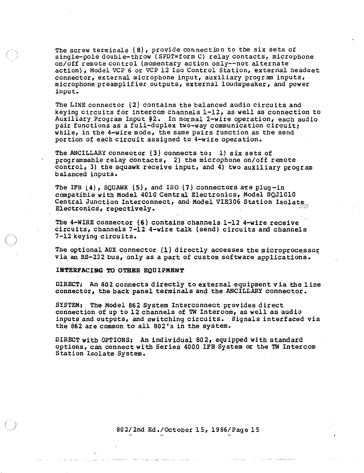
The
screw terminals
single-pole double-throw (SPDT=form
on/off remote control (momentary action only--not alternate
action), Model VCP
connector, external microphone input, auxiliary program inputs
microphone preamplifier outputs, external loudspeaker, and power
input.
The
LINE
keying circuits for intercom channels 1-12
Auxiliary Program Input $2. In normal 2-wire operation, each audio
pair functions as a full-duplex two-way communication circuit;
while, in the 4-wire mode, the same pairs function as the send
portion of each circuit assigned to 4-wire operation.
connector (2) contains the balanced audio circuits and
18)
,
provide connection to
6
or VCP 12
the
six
sets
C)
relay contacts, microphone
Iso
Control Station, external headset
,
as
well
as connection to
of
,
ANCILLARY
The
programmable relay contacts,
control, 3)
balanced inputs.
IFB
The
compatible with Model 4010 Centr
Central Junction Interconnect, and Model VIE306 Station Isolate,
Electronics, repectively
The 4-WIRE connector
circuits, channels 7-12 4-wire talk (send) circuits
7-12 keying circuits.
The optional
via
IblTERFACIrJG
DIRECT:
connector, the back panel terminals and the ANCILLARY connector.
SYSTEM:
connection of
inputs and outputs, and switching circuits.
the 862 are common to all 802
{4),
an
RS-232 bus, only as a part of custom software applications.
An 802 connects directly to external equipment via the line
The Model 862 System Interconnect provides direct
connector
the squawk receive input, and
SQUAWK
{S)
13)
connects to:
,
and IS0
2) the microphone on/ off remote
{7)
connectors are plug-in
a1
Electronics, Model SQJlOlO
.
f
6)
contains channels 1-12 4-wire receive
AUX
.connector
TO
OTBER EQUIPMENT
up
to 12 channels of
(1)
directly
TW
'
s
in the system.
accesses
Intercom,
1)
six
sets
4)
two auxiliary program
as
Signals interfaced via
of
and
channels
the microprocessor
well
as
audio
<
!
An
DIRECT with
options, can connect with Series 4000 IFB System or the
Station Isolate System.
OPTIONS:
individual 802, equipped with standard
TW
Intercom
Page 22
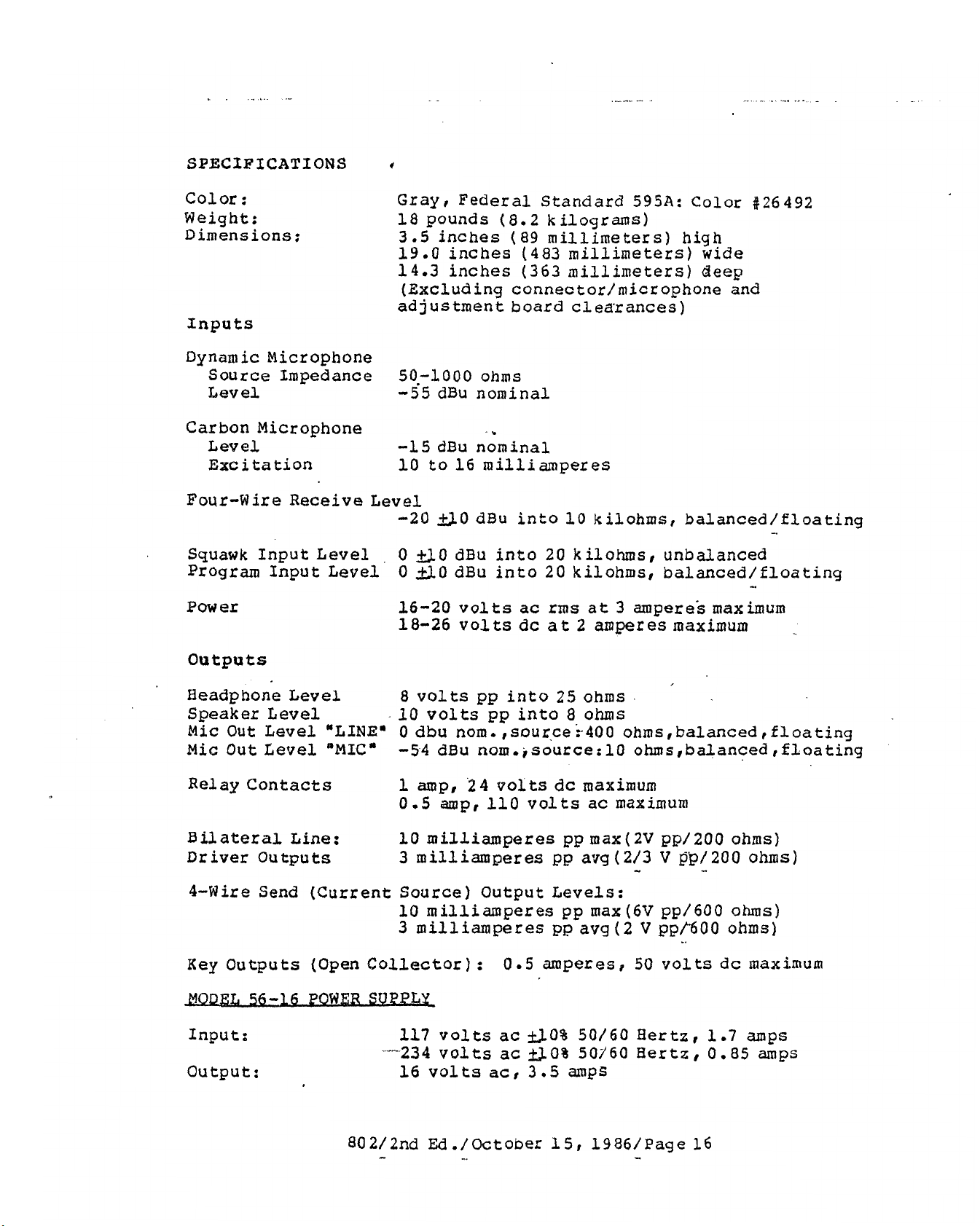
SPECIFICATIONS
f
Color:
Weight: 18 pounds (8.2 kilograms)
Dimensions:
Inputs
Dynamic Microphone
Source Impedance 50.-1000 ohms
Level -55 dBu nominal
Carbon Microphone
Level
Excitation 10 to 16 milliamperes
Four-Wire Receive Level
.
Squawk Input Level , 0 f1.0 dBu into 20 kilohms, unbalanced
Program Input Level 0
Power
Gray
3.5
19.0 inches (483 millimeters) wide
14.3 inches
adjustment board clearances)
-15
-20
16-20 volts ac
18-26
,
Federal Standard
inches (89 millimeters) high
(363
(Excluding connec tor/micr ophone
millimeters) deep
595A:
..
dBu nominal
&).(I
dBu into 10 kilohms, balanced/floating
SO
dBu into 20 kilohms, balanced/floating
rms
at 3 ampere's maximum
volts
dc
at
2
amperes maximum
Color t26492
and
-
Outputs
Headphone Level
Speaker Level
Mic
Out
Level
Mic
Out Level
Relay Contacts
Bilateral Line:
Driver Outputs
4-Wire Send (Current
Key
Outputs
Input:
Output:
"LINE"
"MIC"
(Open
Collector) : 0.5 amperes
8
volts
10 volts
0 dbu
-54
1
amp,
0.5 amp, 110 volts ac maximum
10 milliamperes
3
milliamperes pp
Source)
10 milliamperes pp max
3
milliamperes pp avg
117 volts ac
-..--234 volts
16
volts acI
pp
into
pp
nom.
dBu nom. ,source:lO ohms, balanced ,floating
,source :.400 ohms,balanced ,floating
24
volts
Output Levels:
ac
25
ohms
into 8 ohms
dc
maximum
pp
max(2V pp/200 ohms)
avg(2/3
(2
GO%
SO%
3.5
SO/
60 Hertz,
50160 Hertz
amps
-
(6V
V
50
V
pp/200
-
pp/600 ohms)
ppfi00 ohms)
volts dc maximum
I
1.7
0.85
ohms)
amps
amps
Page 23
MECHANICAL INSTALLATION
(or console) mountable enclosure, 3.5 inches
inches
holes are standard
minimum of 5.0 inches
adjustment board requires
2.0 inches (51
When installing this station, allow space for control access,
cabling and servicing.
connectors, and cables.
located, allow space between this cable and interfering sources
such as
power supplies.
(
483
mm)
wide
mm)
TV
monitors, power supplies and equipment with internal
by
E.I.A.
(127
for the rear panel connectors.
The 802 Speaker Master Station
(
89
mm)
14.3 inches (363
spacing.
mm)
front panel clearance, and the
11
inches (279
Provide space for
If the headset connector
mm)
deep.
The panel micropbne requires a
mm)
:
Allow
.
cab1 ing service loops,
high by 19.0
The mounting
an
.
is
remotely
is
a rack
additional
The Model 56-16 power supply, when used should be mounted at least
to 2 feet away from the Model 802 to minimize hum pickup.
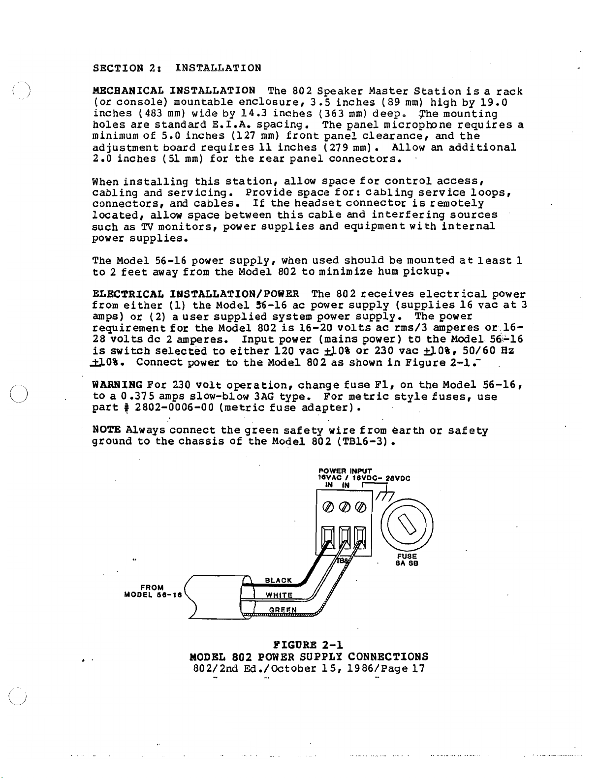
ELECTRICAL IISTALLATION/POWER The 80 2 receives
from either
amps) or
requirement for the Model 802
28 volts dc 2 amperes. Input power (mains power)
is
switch selected to either 120 vac
SO%.
WAEWING
to a 0.375 amps slow-blow 3AG type. For
part
NOTE Always connect the green safety
ground to the chassis of the Model 802 (TB16-3)
Connect power to the Model 802
#
2802-0006-00
(1)
the Model 56-16 ac power supply (supplies 16 vac
(
2) a user supplied system power supply.
is
16-20 volts ac rms/3 amperes or 16-
SO%
For 230 volt operation, change fuse Fl, on the Model 56-16!
(metric
fuse adapter)
or 230 vac
as
shown in Figure 2-1
metric
style fuses, use
.
wire
from earth or safety
.
POWER INPUT
I
IN
IN
1BVDC- 28VDC
ldVAC
electr
The power
to
the Model 56-16
GO%,
ical
50/60
.-
power
at
Hz
/f7
1
3
FROM
MODEL 68-18
@
FUSE
.
BA 88
I
1,
WHITE
\
MODEL
802/2nd Ed./October 15, 1986/Page 17
802
-
GREEN
FIGURE
POWER
-.
//
/
2-1
SUPPLY
CONNECTIONS
-.
Page 24
.ELECTRICAL INSTALLATION/GROUNDINC
Master
S tat*ion,.ch,assis
The
should be connected to earth ground or power line safety ground.
Each Master Station
bypassed to
its
own
chassis
via a
is
0.1 microfarad capacitor and 22 kilohm resistor in qarallel to
prevent interference from radio stations.
ELECTRICAL
IBSTALLATION/
SIGNALS/
-
GENERAL
-.
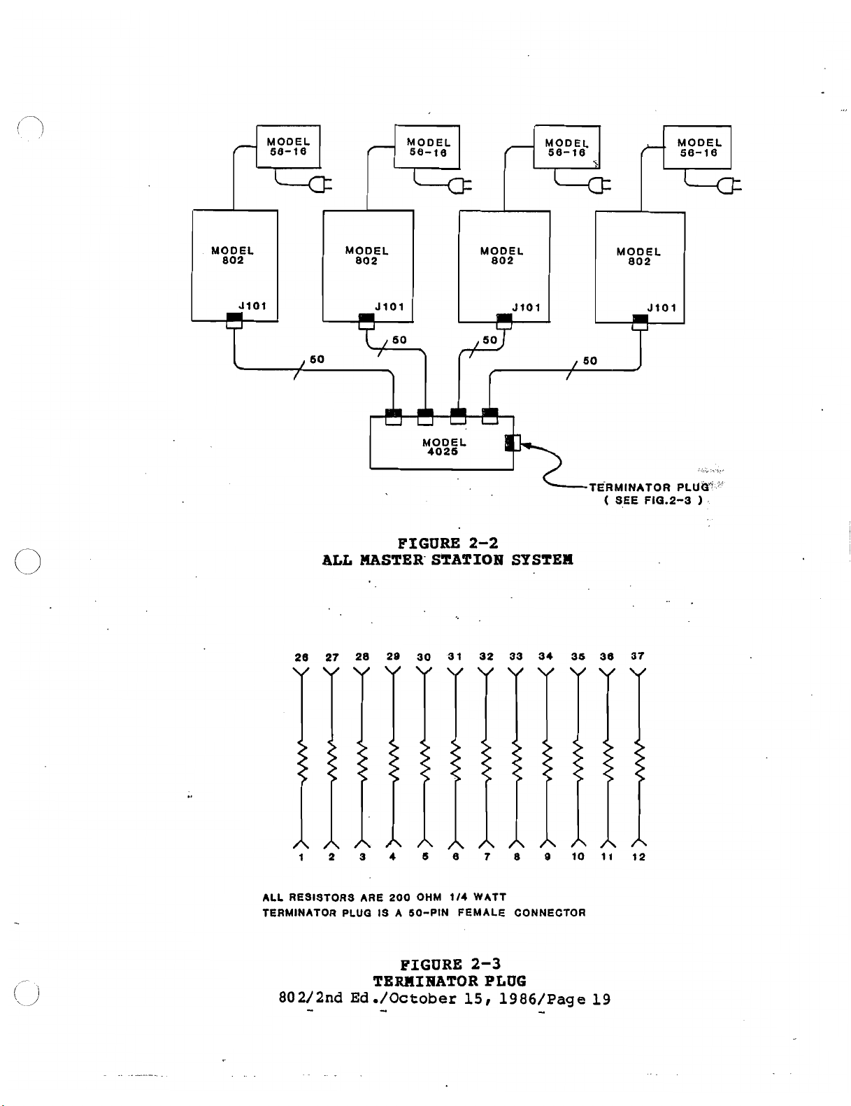
Model 802 system configurations are:
1)
All
Model 802
2) Model
802 Master Station
3) Model 802 Master Station(s) plus
In the "All
Master
Master
Station
Station(s)
(s)
&
Model 862 System Interconnect
(s)
Configuration"
TW
Intercom System
(see
Figure 2-2)
t
interconnect the stations using Model 4025 splittez assemblies.
Connect the Model 802
splitter
assembly as shown in Figure 2-2. Terminate the system by
LINE
connectors (J-101) to the Model 4025
connecting terminator plug of Figure 2-3 to Model 4025.
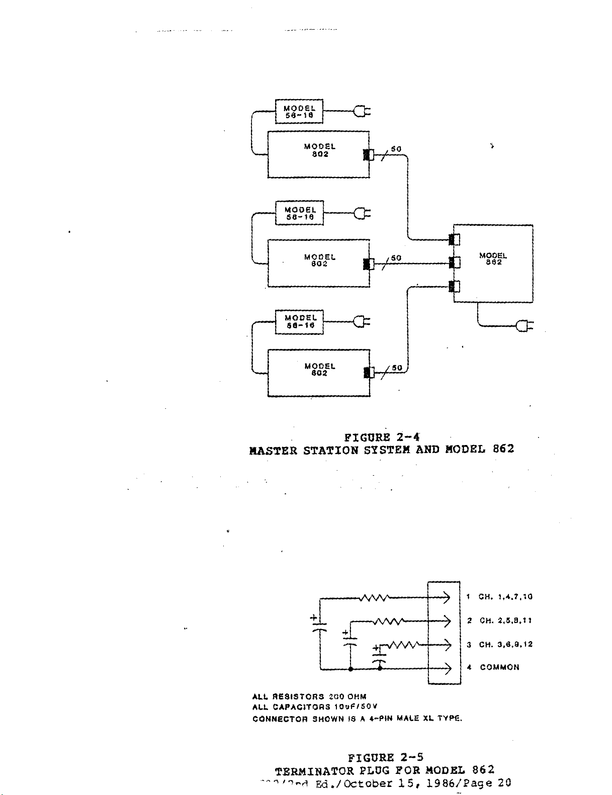
In the
'Master
Figure 2-4)
connectors on the
assemblies or a combi-nation of both.
necting terminator plugs (Figure 2-5) to
el
862,
Two
terminators
system, install terminator plugs in Model 862
'CH
4-5-6* (J6) connectors.
terminator plugs in Model 862
"CH
7-8-9" (57) , and
Station(s) and Model 862 Configurationw
(see
interconnect the stations using either the mu1 tiple
rear
of the Model 862, Model 4025 splitter
Terminate the system by con-
jacks
terminators
are
required for a 12-channel system.
are
required for a 6-channel system. Four
On
"CH
"CB
10-11-12' (J8)
a
12-channel system install
1-2-3" (J5)
.
55-9\18 of the
On a 6-channel
"CB
1-2-3'
I
"CH
4-5-6" (561,
Mod-
(J5)
and
To mechanically secure the cable to the Model 80.2 rear panel:
(1)
Remove the
(2)
Plug
(3)
Secure the cable connector by screwing the captive screw in the
the cable into 5-101
connector into the hole left in step
(4)
Use
a
cable
the cable
Caution
tie
Using one
cable connector may damage
screw
tie
to
loop on
screw
just to
the
left of 5-101
t
(l),
r
above,
secure the other side of the connector, using
the
rear panel of the Model 802.
only (and omitting cable
rear
panel connector.
tie)
to
secure
Page 25
r"9:"h
MODEL
FIGURE
ALL
MASTER' STATIOB SYSTEM
2-2
-TERMINATOR
(
SEE Fla.2-3
PLUW
'
ALL RESISTORS ARE 200 OHM
TERMINATOR PLUG IS A 60-PIN FEMALE CONNECTOR
FIGURE
TERMINATOR PLUG
802/2nd
-
Ed
./October
-
114
WATT
2-3
15,
1986/Page
-
19
Page 26
Page 27
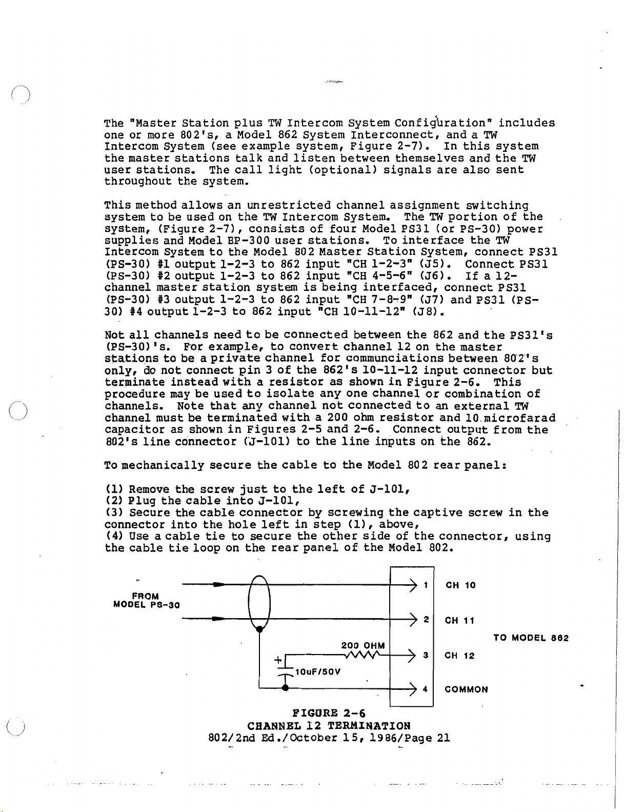
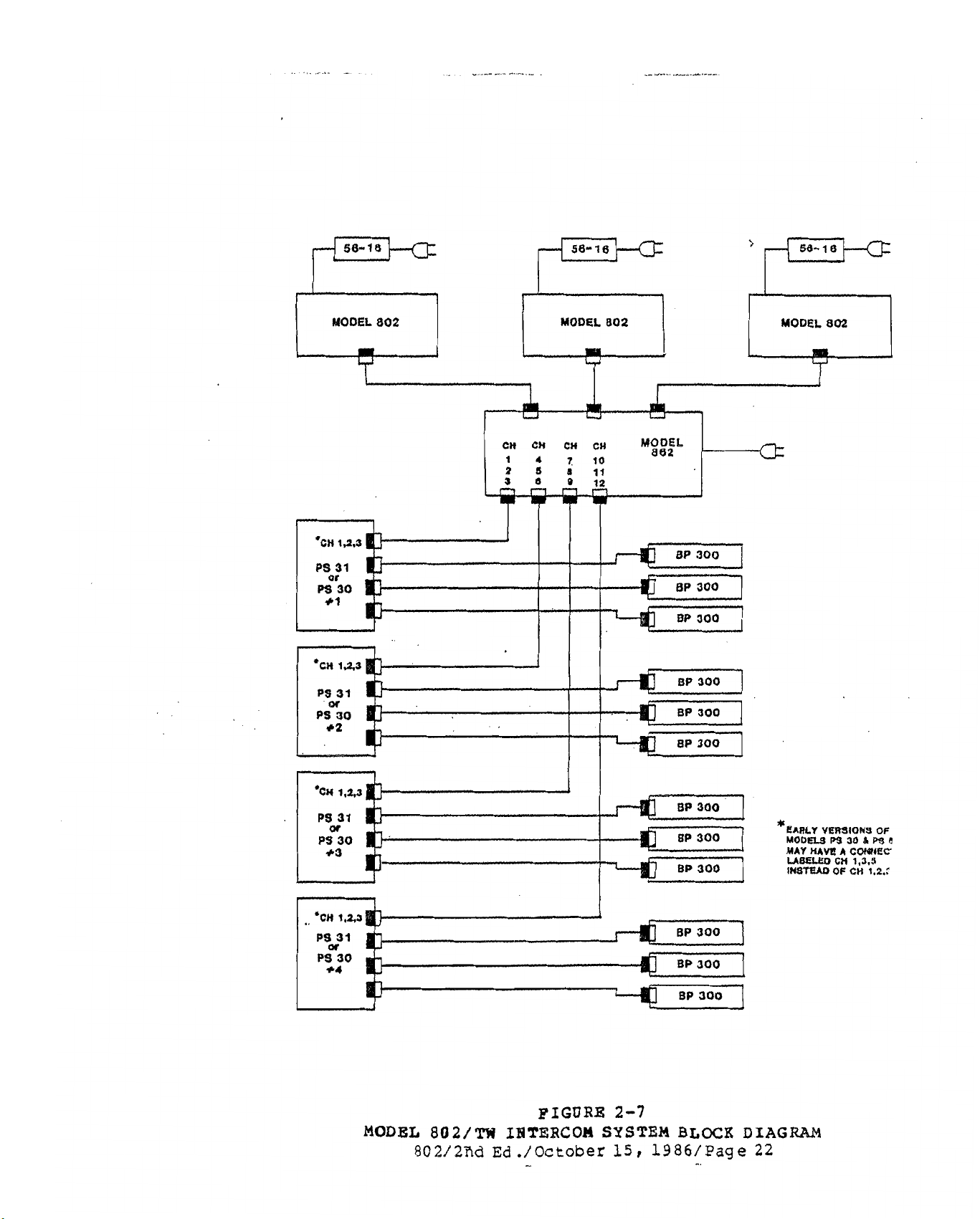
The "Master Station plus
one or more 802Is, a Model 862 System Interconnect, and a
Intercom System
the master stations talk and listen between themselves and the
user stations, The call light (optional) signals are also sent
throughout the system.
This method allows an unrestricted channel assignment switching
system to be used on the
system, (Figure 2-71
supplies and Model BP-300 user stations.
Intercom System to the Model 802 Master Station System, connect PS31
(PS-30) #l output 1-2-3 to 862 input
(PS-30) #2 output 1-2-3 to 862 input
channel master station system
(PS-30) #3 output 1-2-3 to 862 input
#4
30)
output 1-2-3 to 862 input "CH 10-ll-12R (J8).
(see
TW
Intercom System ~onfi~bration" includes
TW
example system, Figure 2-71. In this system
TW
The
TW
TW
Intercom System.
,
consists of four Model PS31 (or PS-30) power
To interface the
"CH
1-2-3" (55). Connect PS31
"CH
4-5-6" (56). If a 12-
is
being interfaced, connect PS31
"CH
7-8-9" (57) and PS31 (PS-
portion of the
TW
Not all channels need to be connected between the 862 and the PS3l
(PS-30)
stations to be a private channel for communciations between 802Is
only, do not connect pin 3 of the 862's 10-11-12 input connector but
terminate instead with a resistor
procedure may be used to isolate any one channel or combination of
channels,
channel must be terminated with a 200 ohm resistor and 10 microfarad
capacitor as shown in Figures
802's line connector (J-101) to the line inputs on the 862,
To mechanically secure the cable to
1
Remove the
)
Plug the cable into 5-101,
1
Secure the cable connector by screwing the captive
connector into the hole left in step
(4)
Use
the cable
For example, to convert channel 12 on the
Is,
as
shown in Figure 2-6.
Note that any channel not connected to
2-5
and 2-6,
the
Model 80 2 rear panel:
a cable
tie
loop on the rear panel of the Model 802.
screw
tie
just to the
to secure the other side of the connector, using
left
of 5-101,
(11,
above,
Connect output from the
master
an
external
screw
This
TW
in the
s
n
FROM
MODEL
PS-30
-
-
+b
10uFI50V
200
OHM
1
>2
3
4
CH
10
CHI1
CH
12
COMMON
TO
MODEL
-
FIGURE
CHANNEL
802/2nd Eld./October 15, 1986/Page 21
-.
12
2-6
TERMINATION
-
882
-
Page 28
MODEL
802
MODEL
802
MODEL
802/m
802/2nd
FIGURE
IBTERCOI
~d
./October
-
2-7
SYSTEM
15,
1986/Page
BLOCR
'EARLY
MOOUS
MAY
UQELeD
INSTEAD
DIAG
22
V~IONS
PS
30
HAW2
A
CWEC
CH
1,3,8
OF
cn
B
P3
1.2.2
OF
6
Page 29
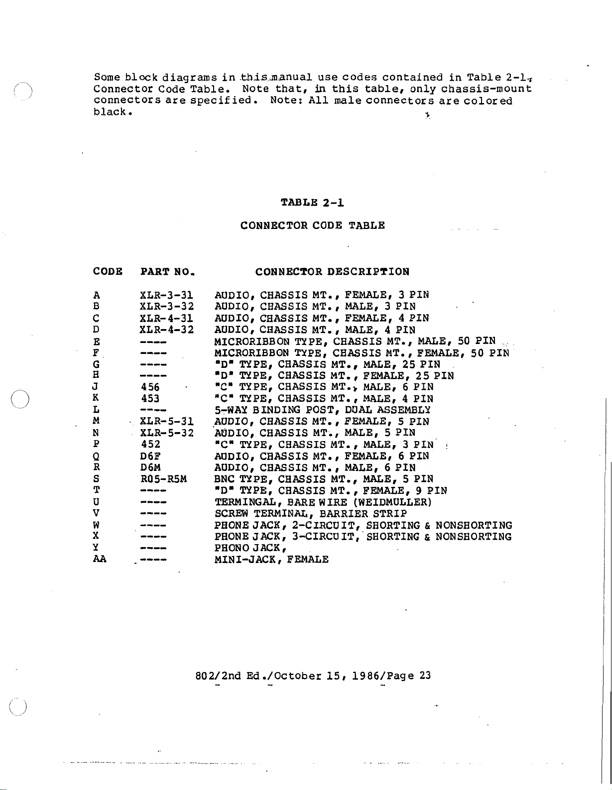
Some block diagrams in .th,is,manual use codes contained in Table
Connector Code Table.
connectors
are
specified.
black.
Note
that,
Note:
in
this table, only chassis-mount
All
male
connectors
are
colored
r
2-1-
TABLE
CONNECTOR CODE TABLE
CODE PART NO. CONNECTOR DESCRIPTION
AUDIO, CHASSIS MT.
AUDIO, CHASSIS MT.
AUDIO, CHASSIS MT.
AUDIO, CHASSIS MT.
MICRORIBBON TYPE, CHASSIS MTo, MALE, 50 PIN
MICRORIBBON TYPE, CHASSIS MTo FEMALE, 50 PIN
"Dm
TYPE, CHASSIS MT., MALE,
"Dm
TYPE, CHASSIS MT.
"C" TYPE, CHASSIS MT.) MALE,
"C" TYPEl CHASSIS MT. MALEl
5-WAY BINDING POST, DUAL ASSEMBLY
.AUDIOI CHASSIS MT.
AUDIO, CHASSIS MT-I MALE, 5 PIN
"C"
TYPE, CHASSIS MT. I MALE,
AUDIO, CBASSIS MT.
AUDIO, CHASSIS MT. MALE,
BNC TYPE, CHASSIS MTm, MALE,
"Dm
TYPE, CHASSIS MTo , FEMALE, 9 PIN
TERMINGAL, BARE WIRE (WEIDMULLER)
SCREW TERMINAL
PHONE JACK, 2-CIRCUIT, SBORTING
PHONE JACK, 3-CIRCU IT
PEON0 JACK
MINI-JACK, FEMALE
2-1
I
FEMALE,
I
MALEl 3 PIN
FEMALE,
,
MALE,
FEMALE, 25 PIN
FEMALE,
I
FEMALE,
,
BARRIER STRIP
I
'
SHORTING & NONSHORTING
4
6
3
4
PIN
5
6
PIN
PIN
PIN
25
6
4
PIN
3
PIN
5
PIN
PIN
PIN
PIN
PIN
61
NONSBORTING
Page 30
JlOl
KEY
OUTPUT
-
-
FROM COMPUTER
i
N400
FIGURE
DABLIBGTON
1
RELAY
I
2-8
KEY
OUTPUT
)
FROM KEY OUT
'
FROM KEY RETURN
KBY
802/2nd
FIGURE
OUTPUT
Ed./October
2-9
APPLICATION
15,
1986/Page
24
Page 31

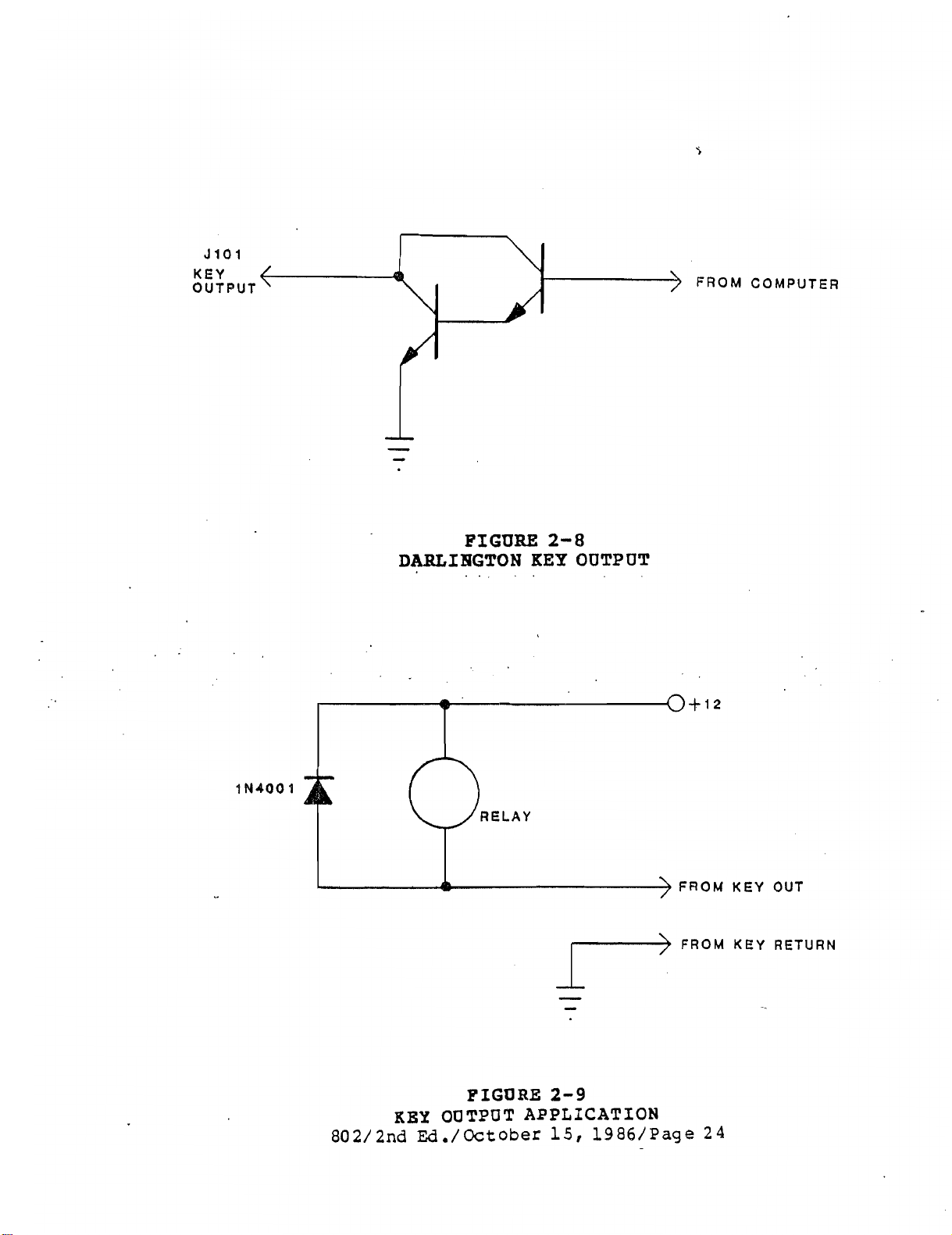
ELECTRICAL INSTALLATION/ SIGNALS/FEATURES
KEY
OUTPUTS
Twelve logic-type outputs are available
.-
.
-.
at
reear-pankl line
I
I
1
connector, 5101. These outputs control relays in the Model 862
System Interconnect, but if your system does not include a Model
862,
these outputs may be used directly
as
control outputs.
Pressing one of twelve talk buttons on the front panel of the Model
802 activates one of the twelve key outputs (respectively)
Connections to these outputs are shown on
sheet
20 of the Model 802
schematic. Figure 2-8 shows a typical output. The darling ton
transistor output conducts to ground, when activated, and has
a
maximum rating of 50 volts, 50 milliamperes, dc. Figure 2-9 shows
an
application of the key output.
Note:
relays should always have a
diode to protect the transistor in the Model 802.
RELAY
OUTPUTS (See Figure 2-10)
Six form C relay contacts are available on the Model 802 rear panel.
The respective relays are programmable from the front panel to
3)
.
operate with front panel pushbutton(s) (See Section
1
contact ratings are:
ac.
Relay programming
Note: Applying voltages over 32 volts
is
EXTERNAL MICROPRONE SWITCH
an
Connect
external or remote microphone switch to TB7 (using labels
above TB7 for exact connection).
microphone
ON
switch being.brightened.
will
turn on and
action and requires
amp at 24 volts dc, or 0.5 amp
is,not recommended.
discussed in section 3.
(
See Figure 2-10)
When the
will
b.e indicated by
switch
The remote switch
a
maintained. contac
ti
When
is
the
is
not alternate
the
at
front-panel MIC.
remote switch
Maximum
110 volts
closed the
off, the microphone may be turned on locally, but when the remote
is
on,
switch
the microphone may
not
be turned off locally.
is
Page 32

-
MODEL
.-
'802
.
.
FIGURE
REAR
PANEL
2-10
CONNECTIONS
Page 33

VCP
CONNECTOR
(See Figure 2-10)
The rear-panel terminal block,
a
uvideo~'i'sW"
EXTERNAL HEADSET
^system,
CONNECTOR
and,
Connect external headphones to TB9.
headphones connections
are
connections, or oscillations
the
f
ront-panel headset connector; use only one at a
EXTERNAL
MICROPHONE
CONNECTOR
An external microphone may be used in place of
TB8,
has
connections to interface to
also, a "squawkn system.
(See Figure 2-10)
-i
Make
sure that the external
separate from any microphone
TB9
is
will
occur.
paralleled with
time.
(See Figure 2-10)
the
front-panel
gooseneck microphone by connecting the external microphone to rear-
panel terminal block
TB10. When using an external microphone,
disconnect the front-panel microphone by unplugging connector, P1,
from the motherboard.
Electret
wire
electret
microphones may also be used
with
the Model 802. Both 2-
and 3-wire microphones are accomodated.
R3
microphone, install resistor
on the mother board.
To use a 2-wire
PROGRAM INPUTS (See Figure 2-10)
Connect external program inputs to rear-panel terminal blocks
TBll
and TB12. These inputs accept line-level balanced audio. Program
volume level
adjustment board pots 15 and 16, and front-panel MASTER
control.
is
controlled by front-panel
AUX
VOLUME control,
VOLUME
Program may be assigned to left headphone, right
headphone, or speaker by switches on the adjustment board.
Alternatively,
Program
System Interconnect to all
Program input #2 of any Model 80 2
82
audio may
master
be
injected
at
the Model 862
stations, or audio appearing
will
appear on all Model 802
at
's.
MICROPHONE OUTPUT CONNECTORS (See Figure 2-10)
Two microphone outputs are provided via rear-panel terminal blocks
A
TB13
high level
and TB14.
(LINE)
determines whether
EXTERNAL
Connect
SPEAKER OUTPUT (See Figure 2-10)
an
external speaker to rear-panel terminal block TB15.
Since this output
rear-panel
output.
an
is
a
SPEAKER LEAD CONTACT
the
internal speaker
output
bridging-type output,
GROUND.
.
'
LEVEL
A
separate MODE switch for each output
is
switch
selects
controlled by the
DO
NOT
low level (MIC) or
MIC
ON/OFF switch.
-
LET EITBER
The switch next to TB15 turns off
Page 34

ELECTRICAL INSTALLATION: HEADSET(S)
A
HEADSET
Dynamic microphone headset type:
REQUIREMENTS:
wide range of headset types may be used:
Carbon microphone headset type:
s
50 to 1000 ohm microphone
25 to
Use
impedance
good acoustic isolation (20 to 40 dB) improve communication in high
ambient noise environments, and allow the user to use the headphones
at
In the headset connecting cable, prevent coupling between the
microphone and headphone leads by using
the microphone, and
not allow headphone ground to contact microphone ground or shield.
Tie the shield to microphone ground or "mic low".
can be made longer when
physically separated. The
cable length which may be used. Estimated maximum usable headphone
cable
1000 ohm headphone
headphones with an impedance of
8
ohm headphones
a
less tiring , lower volume.
lengths
are
as
(s)
are
a
separate, twisted pair for the headphones. Do
the microphone and headphone pairs are
w
f
oblows:
Standard carbon microphone
25
to 1000 ohm headphone
25
ohms or greater.
not recommended. Headphones with
a
shielded, twisted pair for
The headset cable
ides the separation, the longer the
(s)
Low
.
Single cable, two shielded twisted pair: 10 feet (3.05
Dual ribbed cable, two shielded twisted pair: 30 feet (9.14
Separate cables,
Balanced microphone input: up to
shielded
twisted
pair in each:
LOO
feet (30.48
50 feet (15.24
m)
.
m)
.
m).
m)
.
HEADSET CONNECTIONS
Dynam'ic Microphone headset connector
Input level: -55 dBV nominal
Output level to headphone: 10 volts peak-to-peak open circuit.
1
-
Pin
Pin
Pin
Pin 4
Pin
Carbon Microphone headset connector: Standard
(TRS)
Input level: -15 dBV nominal
Phone Jack
Output to Headphone: 10 volts peak-to-peak open circuit.
Tip
Ring
Sleeve
Microphone low
2
-
Microphone high
3 - Headphone low
-
Left Headphone high
5
-
Right
-
Carbon Microphone
-
Headphone
-
Common/ground
Headphone high
-
:
XLR-5-31 type receptacle
l/
4'
Tip-Ring-Sleeve
-
Page 35

ELECTRICAL INSTALLATION/ SIGNAL/MODEL 802 TO MODEL 801/MODEL
86 0
- -
-
If the Model 802
connector on the rear panel of the Model 802 plugs ,directly into an
"801' type system.
it
is
If
type system, follow the directions below.
Case
Monitor Mute:
six channel "801" system.
channel Model 802 to an 801 system
button legends per Figure 2-12.
Case 2: Six channels of intercom, SA's, IFB1s, Slate, Monitor Mute:
Use
connect using the wiring diagram in Figure 2-13. Install button
legends per Figure 2-14.
860. In a 12-channel 802, program one of
when SLATE
*mic/radio-telephone relay available on J2 of the Model 801.
-
Program another relay to activate when SPKR MUTE
relay
54 on an 801. This relay may also be programmed to activate when an
SA button
studio speaker nearest the 802 may
SA1 button
required that a non-801 emulate type 802 be used in an '801U
1:
Six channels of intercom, no SA1s, no IFB1s, no Slate, no
a 12-channel Model 802 (equipped with the Talk option) and
MIC
is
equivalent to the monitor mute relay contacts available at
is
pressed. Thus if SA1
is
has
Use
a standard six channel Model 802 to connect to a
is
pressed.
pressed.
been equipped with an '801 emulateU option, a
A
This
This
wiring diagram for connecting a
is
shown in Figure 2-11. Install
wiring
This
will
will
relay
is
used as a studio announce, the
be
prevent feedback squeals.
operate all relays in the
the
relays to activate
is
equivalent to the slate-
is
pressed.
muted via the relay when
6-
This
its
.
Model 801
between the systems as shown in-Figure 2-15.
termination
connections
talk and listen channels of the 801 to communicate with the first
six talk and listen channels of the 802. The optional connections
interface the next five channels of the 801 to channels
802. SA and
listen. SLATE
Listen level on the SLATE line
knob. The key connections allow the 801 to oserate relays
the 862.
For more information on 801/860 systems,
manual, TM26 04.
I's
may also be used in an 8021 862 system.
is
provided by only one system. Note that some
are
optional. The standard connections allow the six
IFB
channels on the 801 can only talk and can not
is
a 2-way line and
will
is
work to both talk and listen.
controlled by the
-
see
Make
the 801 technical
connectibns
Be
sure that
7
-
11
of the
MT.
2
7
level
-
11
in
Page 36

CASE
TO J101
MODEL 802
.
1:
SIX
ON
,
CHANNEL
FIGURE
802
TO
2-11
SIX
CBABHEL'
TO MODEL 802
THROUGH
LOOP
TO
86111
.
.
PBTERCONNECTION
0
MODEL 860
J8
R
INPUT
CASE
802/2nd
1:
Ed
FIGURE
FRONT
./October
2-12
PAlEL
15,
BUTTON
1986/Page
-.
LEGEZ4D
30
Page 37

?ROY
YODLL 801
YODEL raa
OR
TO J8 ON
YODLL a01
OR
TO YODEL
880
CASE
2:
TWELVE
FIGURE
CBANNEL
802/2nd Ed./October - 15, 1986/Page
802
TO SIX CBANNEL
2-13
801
-.
INTERCONNECTION
31
Page 38

TO
J101
YODEL
OH
802
CASE
2:
FIGURE
FRONT
2-14
PANEL
BUTTON
LEGEND
TO
MODEL
LOOP THROUGH
TO
MOOEL
OR
800
802
INPUT
J8
USXHG
802/2nd
AB
HODEL
Ed
./October
FIGURE
801
IB
2-15
AH
HODEL
15,
802
1986/Page
SYSTEM
32
Page 39

ELECTRICAL INSTALLATION/ SIGNALS/MODEL 80 2/TELEPHONE
-
...
-
The Model 802 may be interfaced to telephone lines as follows.
Method
from an 862 to either a dry or
transformer as shown in Figure 2-16 (Figure 2-10 in 801 manual).
Terminate the phone line with an 820 ohm resistor across the
transformer secondary (phone line side). The transformer
enough so that
(line with dc current) with negligible ac performance degradation;
the secondary
1
ine
Method 2: Connect a TWI-222T-telco interface unit as in
Figure 2-17.
Method 3: Connect
Note: the 200 ohm resistor termination
(PS-30/60)
Method
OPT802-C3) to
work better than the two methods above. Note: Termination must be
provided.
.
-
1:
Connect a party-line (PL) channel from either one 802 or
wet
it
can be directly connected across
is
low enough resistance so that
a
TWI-326 interface unit using Figure 2-18.
is
also connected.
4:
Connect a Model 802 with 4-wire option (OPT802-C2,. ot
a
TWI-3
26 as shown in Figure 2-19.
phone line via a step-up
is
not required if a PS 31
s
a
*wetu
it
will
This method
"hold* the
is
large
line
kill
Page 40

TRIAD 9-64X
$
-0
TIP
FROM YOOEL 680
XETHOD
1:
XODEL
FIGURE
802
TO
620 OHM
A
-
TO TELEPHONE
0
RlMB
LINE
2-16
TELEPHONE Il!?TERCONBECTXOB
MgTBOD
MODEL
2:
802/2nd
TWC222 TO TELCO
-------------
I
I
I
I
I
I
A4Y
FIGURE
802
Ed
./October
2-17
TO
TELILBEONE
15,
I
L
DETAIL OF TELCO CONNECTIOM
,,--------------
IBTERCONNECTION
1986/Page
TO TELCO
RING
"t
34
-1
I
I
I
I
I
I
I
1
I
Page 41

(
ALSO SEE MODEL TWI-328 MANUAL
TO TELCO
)
XETHOD
TO MODEL 802
3:
<
<
<
<
HODEL
200 OHM
200 OHM
FIGURE
802
-
-
2-18
TO
TELEPHONE INTERCONNECTION
MODEL
TWI-328
4W
IN
4W OUT
. .
TO TELCO
METHOD
4:
MODEL
802/2nd
FIGURE
$02
TO
TBLEPBONE INTERCONNECTION
Ed,/October
2-19
15, 1986/Page
-.
35
Page 42

ELECTRICAL
The Model 802 may be used in either of two ways with the 4000 series
IFB system. Method "A" uses
output from the Model 802 to drive Models 4001, 4002, or 4003 IFB
Control Stations. Method
IFB control station and requires no external parts, but
require:
that mother board programming switch(es) be actuated and 3)
microprocessor
INSTALLATION/SIGNALS/MODEL
1)
the installation of one or two IFB option boards, 2)
reset
be executed.
-
RBU
-
a
line-level unswitched microphone
emulates either a Model 4001 or 4002
802/SERIES 4000
-
IFB
it
does
a
To use Method
MIC
Use
Manual, TM2594. Note that, on the 4000 series control station,
must be removed and a trace cut. Interconnect the IFB system and
configuee the 4001, 4002, or 4003
described in the IFB Technical Manual TM2594 and Figures 2-20A and
2-208, Move the 802's
UNSW. Do not connect the shield
Method
option base
IFB control station option OPT802-Gb must be installed. To emulate
a
options must
priority needs to be changed, consult the IFB Technical Manual,
TM 2594.
OUTPUT 2 to Models 4001, 4002, or 4003 IFB Control Stations.
the instructions for "Line-level inputs" in the IFB Technical
"B*
model 4002 IFB control station, both the OPT802-G1 and OPT802-G5
installed the- "Isom option can not be installed. If the IFB
"An,
IFB (See Figures 21, 22, 23, and 24) requires both an
(OPT802-Al) and IFB option
connect the Model 802 (rear panel)
f.or
power input and priority
LEVEL
be
installed. Note that if both IFB options are
switch to LINE and the MODE switch to
at
the 802 end
(s)
.
of
To emulate a model 4001
MIC
OUTPUT
the cable.
1
ot
R11
as
Page 43

TYPICAL CONFIGURATION
+
1
CENTRAL
METBOD
".Aa
t
802/2nd
-
FIGURE
MODEL 802
Ed
./October
-
TO
2-20A
IPB
CONNECTION
15,
1986/Page
-
37
(
4
IPB
s)
Page 44

TYPICAL CONFlC10RATION
+a
CIMTRAL
ILlCTnOMlf,
METHOD
t
MODEL
.Am
802/2nd
1.4
oCC1TT1n
.
PIGUBX
802
TO
Ed./October
2-20B
IFB
COPJNECTION
15,
1986/Page
!--++=I
(
-
38
MOO.
4010
MOO.
4010
8.
IPB's)
Page 45

CONTROL
YQ0.L 400.
MOO. 4010
w
MBTEOD
FIGURE
.Ba
r
HODEL
802/2nd Ed./October 15, 1986/Page 39
802
tO
2-21
IFB
COQNBCTION
(
4
IFB
'8)
Page 46

TYPICAL
CONfl(lURATl0N +2
w
UOO.
4010
METHOD
.Bar
MODEL
802/2nd
PIGIIRX
802
TO
Ed./October
2-22
IPB
COSINECTIOEI
15,
1986/Page
(8
40
IFB's)
Page 47

I
HODEL
802
PROm
FIGURE
PABEL
2-23
BUTTON
ARRABGEHEBT
..
[
ELECTRONIC SWITCH ACTION:
FOR
-
4
IFB8
s
~~~~~~~~~~~$~~~
I
4
I
MODEL
I
&iikE
1
olsmu 1 uoor 1 aEcrrr 1 ExcLuoE I PuRPosE
802
FRONT
802/2nd Ed
LATCH
SET-UP BUFFER PRESET SPECIAL
FIGURE
PANEL
BUTTON ARRAlDGEHEaT FOR 8 IPB
./October
2-24
15,
1986/Page
MASTER AUX
I
VOLUME
VOLUME HEADSET
'
-.
41
CARE MIC
s
Page 48

ELECTRICAL
The Model 802 may be used in either of two ways with the series 1000
squawk system. Method
squawk station that
in the 802. Method
no
with
For Method
802 to the EXTERNAL
shown in Figure 2-27. Connect the MCP-1010's OUTPUT
LINE to the SQUAWK input at TB8 on the 802.
external parts required.
INSTALLATION/ SIGNALS/ SERIES
is
'A"
squawk, connect
LINE
-
"Aa
requires an external model MCP-1010
connected to use the microphone and speaker
'8"
emulates a model MCP-1010 squawk station
LEVEL MICROPHONE INPUT
-
MIC
OUTPUT 1 or
10 0
0
SQUAWK
MIC
OUTPUT 2 of
of
the MCP-1010 as
TO
CONFERENCE
the
Incoming audio level~from the MCP-1010
Level adjust on the 802's pull-out adjustment boasd only and
affected by
1010'
For Method
squawk options are available. The first option OPT802-F1
emulate only the
option OPT802-F5 adds on to the first option so that all ten
channels on an MCP-LO10
OPT802-A1 option base
Incoming audio level
level pot only and
f
sont-panel speaker switch,
80 2 or MCP-1010
"Ba
squawk, the SQUAWK option must be installed. Two
f
irst
(See
is
is
not affected
f
ront-panel level control or 80 2/MCP-
six channels of an MCP-1010. The second
are
emulated, Either option requires the
Figures 25 I 26 I and 28)
controlled by the adjustment board squawk
by
is
controlled by the SQUAWK
front-panel
.
VOLUME
is
...
will
control.
not
Page 49

I
ELECTRONIC SWITCH ACTION,
~~,"~~~~$,~~~~~~,"
I
--
4
I
HODEL
1
E
802 FROlllT
UTCH SET-UP BUFFER PRESET SPECIAL
1
1
1
MOO.
PANEL
I
RECALL 1 EXCLUDE
FIGURE
BUTTON
I
PUFiPOSE
2-25
I
ARRANGEHEBT
MASTER AUX CARE MIC
VOLUME VOLUME HEADSET
FOR
6
SQUAWK
's
MODEL 802 FRONT
802/2nd Ed
PANEL
./October
FIGURE
BUTTON
ARMGEMEBT
2-26
15,
FOR
1986/Page
MASTER AUX CARE MIC
VOLUME VOLUME HEADSET
10
SQUAWK
43
'
S
Page 50

EXT
LL'
MIC
IN
OUT
TO
CONF. LINE
TBT
/
MODEL
802
METHOD
802/2nd
.A9
-.
FIGURE
MODEL
802
Ed,/Cctober
2-27
TO
SQUAWK
15,
1986/Page
L
CONNECTION
44
Page 51

1 ZOVAC
50160
HZ
INWT POWER
-
MOOEL SdJ- 10 10
SQUAWU JUNCTION
I
NOTES:
METHOD
802/2nd Ed./October
a
THIS STATION MAY BE IN ANY POSITION
MODEL 802's MAY ALSO
FIGURE
..I3
',
t
MODEL
80
(I
BE
USED IN MQRE THAN ONE POSITION.
THROUGH 101
2-28
2
TO
SQUAWK
15,
1986/Page
CONNECTION
45
Page 52

The Model 802 may be used in either of two ways with the VIE-306
video iso electronics, Method
video iso control panel. Method
"A"
requires a model VCP-6 or VCP-12
"B"
will
emulate a model VCP-6
video control panel station and requires no external parts.
Method
control panel. Connect the video control panel
panel
Method
"A"
VB
CONN
"B"
video iso requires an external VCP-6 or VCP-12 video
to
the 802 rear-
terminal block as shown in Figure 2-30.
video iso
will
emulate a model VCP-6.
To use this option
IS0 option OPT802-H1 must be installed along with option base
OPT 80 2-A1.
"B"
Enable IS0 option
(See Figure 2-32) and pushing the RESET button on the adjustment
ON
by moving switch S125-4 on the mother board to
board, Connect output from rear-panel IS0 connector J106 to the
VIE-306 central electronics as showntin Figure 2-31.
With
either IS0 option
enabled. This option wil1,mute
IS0
an
5125-5
case,
channel
the mother board to
on
is
selected. To enable this option, move switch
outgoing party-line channels are disabled during video iso.
REPLACES
MWEL VCP
STATlOH ISOUlT
conmoL
6
STATION
"A"
or
TO UOOEL VIE
STATION ISOLATE
ELECTRONICS
"Bnr
ON
308
IS0
DRIVEN
all
incoming party Line calls when
shown in Figure 2-32,
as
'
TO
TO REMOTE LOCATIONS
VIA 4:WIRE,TELCO CIRCUIT
BNQINEERINQ
*WAY RADIO
TRMSOENE",,~)
LISTEN
KEYING
DISABLE may be
In either
4-WIRE
CYICUITS
TO REMOTE
LOCATIONB
MODEL
802
FRONT
802/2nd Ed./October
PURL
SIX STRANDED
INTERCOM CHANNELS
I
FIGURE
BUTTON
COIHEReHCE
2-WIRE
LW
t
AUDIO VIA MOOEL
I
2-29
ARRAIIGEWBBT
15,
1986/Page
TO TW INTERCOM
INTERCONNECT
FOR
3YSTEM
882
IS0
46
(METHOD
.B"
)
Page 53

MODEL
2/VCP CONNECTOR
4
5
3
2
-130 CONTROL INPUT
AUDIO La
AUOlO HI
GROUND
VCP INTERFACE BOARD
-
3
w
fp,
2
1
-
I
I
T84
'4
8
3
14VAC IN .011500
cs
K
1
ALL CAPACITORS SHOWN ARE IN uFIVOLTS.
METBOD
802/2nd
'Amr
MODEL
Ed./October
FIGURE
2-30
802
.-[r_-L-L-J
TO
IS0
15,
1986/Page
CONNECTION
47
Page 54

MODEL SAP-1026
12
THUMBWHEEL OUTPUTS
I
MODEL
802-A 1 H
PRIORITY
MODEL
VCP-6
-
PRIORITY
-
PRIORITY 3
I
1
1
2
MODEL
VIE-306
@-+-
CAMERAS
6
TO
0
'3
R
R
USER
STNS.
WIRE
TO 6 CAMERAS
TW USER STNS.
j
PLUG IN POWER SIJPPLYnhJ
FIGURE
METHOD
",Bn
r
802/2nd Ed
MODEL
./October
802
2-31
TO
IS0
CONNECTIOM
15, 1986/~age
48
Page 55

FIRMWARE
yb3.0..
CALL ANSWER
INSTANT
IFB on/of f
IFB
8/4
PRESET EXCEUSIV
~ot
Used
COLD START
SET-U
MIC
or IS0
P
DISABLE
ADJUSTMENT
,
ON
1
FIRMWARE
u
FIRMWARE FIRMWARE
-
CALL
Not Used
IFB on/ off 3.
IFB 8/4 or IS01216 4.
PRESET EXCLUSIVE
Not
COLD START 7.
SET-UP DISABLE
FIGURE 2-32A
BOARD
AN
Used
COMMAND
SW
ER
SWITCH
AAdL
1
,
2.
"
"
5
'6
;
8.
Not
Used
Not Used
IFB
on/of f
IFB 4/8
PRESE;T EXCLUSIVE
LISTEN FOLLOW TALK
COLD START
SET-UP DISABLE
or
IS0 6/12
CALL LIGHT TIME
TALK 7 -12 ENABLE
ON=801 emulate
IS0 ENABLE
IS0 LISTEN DISABLE
IFB ENABLE
IFB SELECT
IFB TALK DISABLE
1.
CALL LIGHT TI'ME OUT
2. OFF-1-6 talk ,ON=7-12 talk
3. ON=801 emulate
4.
IS0 ENABLE, OFF=external contact, ONtbuttons
ONtdisable listen buttons when IS0 active
5.
6.
ON=ISO enable
7. ~otUsed
ON=disable talk buttons when IFB
8.
FIRMWARE
8
128
1.
2.
3. ON=801 emulate
4.
5.
6.
7.
8. ON=disable talk buttonswhen IFB active
4.7
CALL LIGHT TINE OOT
OFF=l-6 talk ,ON=7-12
IS0 ENABLE, OFF-external contact, ON=buttons
ON=disable listen buttons when IS0
ON-IS0 enable
Not Used
OUT
active
talk
active
FIGURE
MOTHERl30ARD DIP SWITCH ASSIGNMENTS
80212nd ./October 15,19861~age
2-32B
49
Page 56

MODEL
FIGURE
802
FRONT PANEL PROGRAMMING BUTTONS
3-1
Page 57

Model
The SPECIAL PURPOSE programming mode allows the user to
choose additional operating features, described
description includes instructions for the user to implement
the features.
802
SPECIAL PURPOSE Programming Mode Functions
By Karen Hultgren
be1 ow. The
BUTTON LOCK BUTTON LOCK (formerly BUTTON INHIBIT)
to
lock buttons
To lock
button
MODE,
LOCK. Reselect the same buttons you want
locked ON. After you
these buttons
turned OFF or programmed for any other
function except keying relays. You cannot
lock ON
To Lock OFF: Clear display and go into SET
UP MODE. Select SPECIAL PURPOSE, then
BUTTON LOCK. Select button
.
locked OFF. Clear from SET UP MODE and the
selected switches cannot
you'd like to lock OFF
a PRESET turn them ON, program
first and then BUTTON LOCK.
INSTANT MIC INSTANT MIC
TALK button. Standard units
TALK
(TALK Channels 7 through 12)
through TALK 12.
BILAT* SELECT .BILAT SELECT can turn ON
bilat
!
into SET UP MODE,
then BILAT SELECT. Buttons
available
software summary, page 8. Now, assign
button
ON:
(s)
you want locked ON. Go into SET UP
select
PRESETS.
1
through TALK
with a button
bilats,
to
control
ON
or OFF.
First clear display, then
SPECIAL PURPOSE, then BUTTON
will
stay
activates
clear
some
MIC ON
6.
from SET UP MODE,
ON
and cannot
(s)
you want
be
turned
buttons but have
the
PRESET
with
can
Units
can
any
only
with 83 option
use TALK 1
'.
a
normally unused
on
the front panel. Go
select
refer
that
SPECIAL PURPOSE,
to
Appendix
will
flash the
bilat.
ON.
B
is
used
select
be
If
usable
use
4.7
a
,
TOTAL MUTE TOTAL MUTE
buttons keyed ON with the touch of one button
on
the front panel.
programmed for this function and. when
programmed cannot
purpose.
is
used
to
Only
be
used for
turn OFF
one button
all
any
other
can
other
............................................................
*
Bilat
wire
"BILATERAL CURRENT SOURCE FOR A MULTITERMINAL INTERCOM")
means
converter (RTS Systems patent number 4,358,644
bilateral
Page 1 of
current source used
3
/
February 10,1987
as
a
two
:
be
to four
.
Page 58

Model 802 SPECIAL PURPOSE Programming Mode Functions
By Karen Hultgren
CHIME SELECT, AUTO LISTEN,
CALL Option only.
CHIME SELECT CHIME SELECT
only. You have a choice of
tones which are Dissonant Tone, Bell Tone,
Sweep Tone, and no tone. Only
be
used
the Bell Tone which sounds after the software
version
"power up" or RESET.
To change chime tone, go into SET UP MODE.
Select SPECIAL PURPOSE, then
Select desired chime tone whose button
locations
software summary, page
button
of the SET UP MODE
button doubles
To turn Off the chime tones, go
MODE,
SELECT. The available chime tone buttons
will
others, push that button
Nash together.
Note: If the selected Chime
out the adjustment board and adjust
to
select
flash, one being out of phase with the
and AUTO TALK
is
used with Chime Option, El,
at
a
time.
is
shown on the 802 front panel after
are
shown
hear that tone. You'll now
as
the SET UP button.
SPECIAL PURPOSE and then CHIME
is
too
are
used with the
several
one
Normally, the 802 uses
CHIME
in
Appendix
7.
Push CALL SIGNAL
tone can
SELECT.
B
4.7
chime
be
because
loud
the
the CALL SIGNAL
into
so
all
the
or
too soft, pull
"Chime Level" pot.
SET UP
buttons
out
AUTO LISTEN AUTO LISTEN functions
person at a location
pushes his CALL
signal
receiving the
channel's
as
holds down their CALL
allows
call
AUTO TALK AUTO TALK functions the same
except
'
be
This allows the 802 operator to talk back to
the person
touching
Page 2 of
is
received
LISTEN but ton which
long
the
as
as
the person
caller
well
both
keyed ON instead of the LISTEN buttons.
at
any
3
transmit
call
as send
the TALK and
a
remote
but
tons.
/
February 10,1987
as
follows, when
remote
button, a
at
the 802. The channel
signal will key ON that
at
the
transmit
to
vocally
the
call
MIC
location without
a
to a given. 802
call
will
remote
announce their
signal.
as
ON buttons will
remain
location
button. This
AUTO LISTEN
ON
Page 59

Model 802 SPECIAL PURPOSE Programming Mode Functions
By Karen Hultgren
EXT. CONTACT The EXTERNAL CONTACT formerly operated only
ON
TALK TURNS
ON LISTEN
the MIC
now programmable with the default
operating the MIC
the MIC ON
program
CONTACT allows the EXTERNAL MIC switch
.
contacts
be
to
button. Only one button
for this function. You
a
do that, program your PRESET first,
program the EXT. CONTACT
PRESET. To turn
the INSTANT MIC programming feature, above.
TALK TURNS
particular TALK channel button
the TALK'S corresponding LISTEN button
be
will
OFF
used to key
PRESET to turn
automatically keyed ON. The LISTEN button
stay
or
switch. The EXTERNAL CONTACT
state
ON
switch (which means that
will
is
used) . programming
(TB7) located on the 802 rear panel,
not
ON
ON
be
keyed
a
802 front panel
can,
a
group of buttons. To
ON
when this
the
EXTERNAL
can
be
programmed
however, program
then
to
ON
the MIC
ON
LISTEN functions
ON
until the 802 operator pushes
the TALK button
turn
ON
is
pushed OFF.
as
as
is
ON
pushed
well,
whenever
is
that
see
ON,
will
a
it
TALK TUWS TALK TURNS OFF LISTEN functions
OFF LISTEN
particular TALK channel button
. .
the TALKfs corresponding LISTEN button, if
will
ON,
LISTEN button
tor
pushes
OFF.
be
automatically keyed OFF. The
it
will
ON
stay OFF
or
the
TALK
until
button
as
whenever a
is
pushed
the opera-
is
ON,
pushed
Page
3
of
3
/
February 10,1987
Page 60

APPENDIX A
SUMMARY OF 802 SOFTWARE VERSIONS
(7
Version
Added two features:
*
*
Added features:
*
*
*
*
.
*
*
(1) TALK key turns
(2)
TALK key turns off corresponding LISTEN key
Choice of 6 or
Allows assigning of unused bilats to buttons
Displays version number of software
Ability to program a total mute button
Programmable auto listen-on when receiving a call
Auto-Call now progamnnable on ihdividual buttons
10
on
squawks
corresponding LISTEN key
Version
during
.
4.7
4.6
power-on
*
*
*
NOTES on Version 4.6:
1. Versions 4.514.6 are the first to use four EPROM's, previous versions used three EPROM's.
2. Bilat 13/14 talmsten gates not lifted/saved, (For example: during
Choice of 3 chime tones
External (rear panel)
button
Exclusive taWsten feature:
1 talkllisten
mic
pair
contact can
at a time
be
programmed to
(Continued)
any
ISO).
Page 1 of 12
1
July
23,1986
Page 61

.APPENDIX A (Continued)
SUMMARY
OF
802
SOFTWARE VERSIONS (Continued)
Version 4.5
Same as Version 4.6, but not released because of a
Version
This version never issued.
Version 4.3
Correct minor bugs in version 4.2.
Version
Added features:
*
*
Added Global Reset button for VCP6A
and
Instant mic is now programmable to individual buttons
bug:
External Iso doesn't key on the MIC.
4.4
4.2
VCP12A options
Added features:
*
*
Both
Any
IS0
button can
and
IFB
moved to right side of panel
be
programmed to
be
Version 4.1
ignored
Page 2 of 12
1
July 23, 1986
. . . .
-. . . . .
. . -. - .
.
-
-
.
..
.
-.
...
Page 62

DOCUMENTATION SUMMARY SOFTWARE VERSION 4.6
MOTHER BOARD
DIP
SWITCH ASSIGNMENTS
Call light time-out selection.
=
OFF
ON
1-6 talks, ON
=
801 emulation.
IS0 select. OFF
ON
=
disable listen buttons when IS0 active.
=
IS0 system enabled.
ON
=
7-
12 talks.
=
external coitact, ON = buttons.
Not used.
ON
=
disable
talk
buttons when
IFI3
active.
ADJUSTMENT BOARD DIP SWITCH ASSIGNMENTS
Not used (old auto-call).
Not used (old instant rnic).
ON
=
IFB system enabled.
Number of IFB's or ISO's. OFF
Only one preset on at a
time
When talks active, only corresponding listens can
ON
=
Always "cold start".
ON
=
Disable setup mode.
=
6,
ON = 12.
[INTERLOCKING SWITCH ACI7ON-J.
be
SQUAWK BOARD DIP SWITCH ASSIGNMENTS
active.
OFF
=
up to 6 squawks, ON = up to
=
SQUAWK system enabled.
ON
Adjusts which buttons have squawk.
Adjusts which buttons have squawk.
Saves talk when squawk used.
6. Saves listen when squawk used.
CHIME CHOICES
1. Dissonant tone (DISS).
2.
3.
Bell.
Sweep tone (PHaSoR).
10
squawks.
. - ....
3
Page
-
. . - .
. .
. . - .
.
.
.
-
.
. .
.
,
.
.
.
.
of 12 1 July 23,1986
.
.
-.
. . . . .
.,
-.
-
.
.
.
.~
.
-
--
Page 63

APPENDIX B.
SPECIAL PURPOSE FUNCTIONS
4.6
(Continued)
...........................................................
IBUTNIINS-IUN-
lLOCKlTANTlUSEDlAL
I
I
IMIC
...........................................................
I
I I
I
...........................................................
I
IBLTSIMUTEISEL.ILSTNlTALKlTACTl
I
I
I I
ITOT-ICHMEIAUTOIAUT0IEXT.I
I
I
I
I
I
I
I
I
I
I
I
I
I
I
I
CON-
I
I
I
1
I
I
I
I
I
I
I
I
I
I
I
I
I
1
I
I I
I
I
I I
I
I
I
I
I
I
0
[PRE IPRE
ISET ISET
I1 12
IPRE IPRE
ISET ISET
I1 12
IPRE IPRE ICALLIPNL ISPKRl MICl
ISET ISET
13 14
IPRE IPRE ICALLIPNL
ISET ISET
13 14
I
1
I
1
I
*lMICIONIONI
1
*lMICIONIONI
I I I
CHIME SELECT
1
SPKRI MICl
I
I
I
-
101
-
-
101
-
-
101
-
-
101
-
101
101
. ._
_____
setup
Page
4
of
12-1
July
23,1986
..
. .-
.
_.
_,
_
_
-
.
_.. . _. ._
....
,
.-...
..
-
.
-
Page 64

APPENDIX B (Continued)
...........................................................
I
LG
13
A
[OLD
lIS0
ILG
n
I
LG
I
1
14 1 15
n
12 12
I
TG
14
[IS0
ITLK
n
I
1
I
I
I
I
Corresponding Circuit
Points to top row
Buttons.
VERSION INDENTIFICATION (VERSION 4.62 ILLUSTRATED)
(OCCURS ON
I
I
I
-----------------_____---------i---------------------------
...........................................................
I
I I
I
POWER-UP)
I
I
TG
I I I
1
1
13
n n
PI02~PI02~PIOllPI02~PIOl~PI02IPIO2IPIO2I
3
13 15 12 15
BITOlBITl~BIT6lBIT4lBIT71BIT5IBIT6~BIT7~
...........................................................
I
I
11 12
............................................................
-_---------___-_--------------------------------------------
I
I
I1 12 13 14
I
I
I
I
...........................................................
I
1.3
I
I
1
xxxx
I
xxxx
1XXXX15*16
I
I
1
1
-
1
I
15
I
I
1
xxxx
1
xxxx
lXXXXl7
I
I.
17
1
1
I
I
18 19
I
I I
18 19
I
I I
I I I
I
1
I
1
TOP
I
LG
I
I
.
LG
I
1
n
12
I
1
But
16 lton
Row
A
1
.I I I
I
I
I
I I
I I
1
I
I
I.
I
I
I
xxxx
XXXX
<------
xxxx
indicates a lit button.
Page
5
of
12
/
July
23,1986
Page 65

APPENDIX
B.4.7
DOCUMENTATION SUMMARY SO WARE VERSION
MOTHER BOARD
DIP
SWITCH ASSIGNMENTS
Call light time-out selection.
OFF
=
1-6
talks, ON
ON
=
801
emulation.
IS0 select. OFF
ON
=
disable listen buttons when IS0 active.
ON
=
IS0 system enabled.
=
7-12
talks.
=
external contact, ON = buttons.
Not used.
ON
=
disable
talk
buttons when
IFB
active.
ADJUSTMENT BOARD DIP SWlTCH ASSIGNMENTS
Not used (old auto-call).
Not used (old instant
ON
=
IFB
system enabled.
Number of IFB's or ISO's. OFF
rnic).
=
6, ON
=
12.
Only one preset on at a time.
When talks active, only corresponding listens can
be
active.
Always "cold start".
Disable setup mode.
4.7
1.
2.
3.
4.
5.
6.
CHIME
1.
2.
3.
-
OFF = up to 6 squawks, ON = up to
ON = SQUAWK system enabled.
Adjusts which buttons have squawk
Adjusts which buttons have squawk
Saves
talk
when squawk used.
Saves listen when squawk used.
CHOICES
Dissonant tone (DISS).
Bell.
Sweep tone (PHaSoR).
Page
--
-
---
-
-
10
squawks.
6
of
12 I July
23,1986
-
Page 66

APPENDIX
B
.4.7
(Continued)
SPECIAL PURPOSE FUNCTIONS
IPRE
ISET ISET
I1
IPRE IPRE
ISET
I2 (3
.....................
IPRE
[SET
14
ICALLIPNL ISPKRl MICl
I I I
1
*(MICIONIONI
I
----------------
Setup
.......................................
IPRE
ISET
I1
IPRE IPRE
ISET ISET
12 13
.....................
IPRE
[SET
14
ICALLIPNL ISPKRI MICl
I
1
I
*lMICIONIONI
I
----------------
setup
I
CHIME SELECT
I
I
-
I
101
-
- -
1.101
-
-
1011-61
-
1011-61
-
_
_
.
-
. .
-
.._ ..
Page
_._
7
of
12
/
July
23,1986
,
.
. - .
. . .
.
-
.- -..--
-.
..:..-.--.
. .
. .
Page 67

APPENDIX B. 4.7 (Continued)
UNUSED BILATERAL CURRENT SOURCE SELECTION
...........................................................
I
LG
I
TG
14
A
JISO
I
ITLK
A
I
1
I
I
I
Corresponding Circuit
Points to top row 3 13 15 12 15 12 12 12
Buttons.
VERSION INDENTIFICATION (VERSION 4.7 ILLUSTRATED)
(OCCURS ON POWER-UP)
I
I
I
...........................................................
...........................................................
I
I
I
I
I
I
I
TG
I
1
PI021PI021PIOllPI021PIOllPI02IPIO2IPIO2I
I
1
13
A
BITO~BITl~BIT6~BIT4~BIT71BIT5IBIT6~BIT7~
IOLD
lIS0
13 ILG
A
I
LG I LG I LG
I
1
A
I
14 1 15
A
I
1
16 lton
A A
...........................................................
I
I
11 12 13 1XXXX15 16 17 18 191
............................................................
I
I
I1 12 13 14
...........................................................
I
I
I
I I
I
I
I
xxxx
1
IXXXXI'
I
I
I
I
IS
I I
.I
-
I
I
1.
I
I
I I
I.
I
I
I
I
16
1
xxxx
1
xxxx
lXXXXl8 19
1
1
I
I
I
I
1
I I.
I
I
.
I
I
1.
I
I
TOP
I
1
But
Row
1
I
I
.......................................
IPRE- IPRE IPRE IPRF:
ISET [SET ISET ISET ICALLI
11 12 13 14
.......................................
1
2
3
XXXX
XX~
XXXX
4
<------
1
1
IPNL ISPKRI MICI
I I
IMIC I ON I ON
5'
6'
indicates a lit button.
Page
--
-
8
of
7
12
1
8
July
I
I
23,1986
-
-
101
-
-
IOII~
-
-
Page 68

APPENDIX
C
MODEL 802 MASTER STATION - OPTION NUMBERING SYSTEM AND ORDERING SYSTEM
Each option for the 802 is listed as a separate model number (derived from the coding system below)
which always starts with "OPT802-" followed by a suffix containing both a letter and a number. (i.e.
OPT802-B 1).
The suffix letter designates what the option is:
S
Option Base
Talk
4-wire
Signal
Chime
Squawk
G
IFB
H
IS0
I Not to
The
be
suffix
used
number
designates how the option is to
J (future)
K
(future)
L
(future)
M
(future)
N (future)
0
Not to be used
P (future)
Q Not to be used
R
(future)
be
sold/installed:
(future)
T
(future)
U
(future)
v
(future)
W
(future)
x
(future)
Y
(future)
Z
Custom
0
not installed (sold for field installation or
1 factory installed, no assignment required
2
,3
factory installed, in channels 1-6
factory installed, in channels
7-12
4
5
factorv installed.
as
secondarv (additional)
option (i.ddupgrade to: ten squawc c'hannels;
6
C1
I
not installed, as secondary (additional) option
8
9
special instructions required
as
a
spare)
XkB
4002
(Continued)
Page 9 of 12 /July 23,1986
-
-
-
--- - -
-
Page 69

APPENDIX C
(_I
MODEL 802 MASTER STATION
-
OPTION NUMBERING SYSTEM AND ORDERING SYSTEM
(Continued)
OPTION
NAME/
NUMBER DESCRIPTION
,
The RTS Order Acknowledgement ("OA") lists each individual option as a separate line item, normally
listed directly below the associated 802.
Ordering example:
Quantity
Model Description
Master Station
Option Base, installed
Talk,
installed
4-Wire, installed,
ch
7-12
Chime, installed
IFB
4001, installed
"OPTION BASE": REQUIRED TO SUPPORT CERTAIN OPTIONS (INDICATED BELOW).
per
NOTE: only one "OPTION BASE is required
OPT802-A0
'
Option Base, not instaUed
s.
individual 802.)
OPT802-A1 Option Base, installed
"TALK" OPTION: ADDS CIRCUITRY TO CHANNELS 7-12
OPT802-BO TALK, not installed
OPT802-B3 TALK, installed
"4-WIRE" OPTION: ADDS
4-WIRE
CAPABILITU' TO SIX CHANNELS
OPT802-CO 4-Wire, not installed
OPT802-C2
LdWire,
OPT802-C3 4Wire, installed,
installed,
ch
ch
1-6
7-12
(NOTE: OPTION C3 REQUlRES "TALK OPTION B 1)
(Continued)
of
12
1
July
Page 10
23,1986
.
..
-
-
Page 70

APPENDIX C
-
MODEL 802 MASTER STATION
OPTION NUMBERING SYSTEM AND ORDERING SYSTEM
(Continued)
OPTION
NAME/
NUMBER DESCRIPTION
"SIGNAL" OPTION: ADDS CALL SIGNALING CAPABILITY TO SIX CHANNELS
OPT802-DO Signal, not installed
OPT802-D2 Signal, installed,
OPT802-D3 Signal, installed,
ch
ch
1-6
7-12
(NOTE: REQUIRES "OPTION BASE" Al)
D3
(NOTE: OPTION
ALSO REQUIRES
"TALK
OPTION B 1)
"CHIME" OPTION: GENERATES AUDIBLE OUTGOING
OPT802-El Chime, installed, factory only
(NOTE: REQUIRES "SIGNAL" OPTION
02
OR D3)
OPTION
NAME/
NUMBER DESCRIPTION
"SQUAWK" OPTION: PROVIDES DEDICATED
,
(and
MODEL 8 10 'emulate).
OPT802-FO
OPT802-F1 Squawk, installed,
OPT802-F5 Squawk, installed,
-
'
Squawk, not installed
cb
1-6,
ch
7-10
LINE
INTERCOM CAPABILITY
.
(NOTE: REQUIRES "OPTION BASE")
(NOTE: OPTION
ALSO REQUIRES OPTION
F1)
F5
(Continued)
AND
INCOMING SIGNAL
Page 1 1
..
.
.
of
12
1
July
23,1986
.
..
.
.
-.
Page 71

APPENDIX
C
MODEL 802 MASTER STATION - OPTION NUMBERING SYSTEM AND ORDERING SYSTEM
(Continued)
"IFB" OPTION: EMULATES A MODEL 4001 OR MODEL 4002 IFB CONTROL STATION
OPT802-GO IFB, not installed
OPT802-G
OPT802-G5
1
IFB,
400
1,
JFB, 4002,
(IFB
(IFB
1-4,
S
A
1
5-8, SA 2)
(NOTE: REQUIRES "OPTION BASE")
(NOTE: OPTION G5 ALSO REQUIRES OPTION GI)
(NOTE: G1 AND G5 ARE BOTH INSTALLED)
"IS0 OPTION: EMULATES A MODEL VCP6A STATION IS0 CONTROL PANEL
OPT802-HO ISO, VCP6A, not installed
OPT802-H1 ISO, VCP6A, installed
(NOTE: REQUIRES "OFTION BASE")
End
Software
4.7
update
Page
12 of 12 /July 23,1986
--
---
-
--
-
-
.,.-
--
-
-- -
-
-
--.-
Page 72

(3
SECTION
Introduction
3:
INSTRUCTIONS FOR PROGRAMMING
THE
MODEL
'5
s
802
0
There
Hardware and software. The hardware programming
via 'dip switches' and by plugging in option boards. The software
programming
HARDWARE
The
The option boards that effect programming are:
The
The Sigdaling Option board
Option boards)
Plugging in the Talk/Squawk Option board and, setting the dip
switches on
Model
Plugging in the Signaling (Call Light) Option board activates the
Signaling Option.
are two kinds of programming functions on the Model
is
accomplished
FUNCTIONS
hardware "dip switches are located on:
The motherboard, near the back panel,
The adjustment board at the very back.
The Talk/ Squawk Option board.
Talk/ Squawk Option board
-
via the f tont panel buttons,
(s)
..
(s)
. . .
(Also called the
.
it
and the motherboard f or 'Squawk' functions causes the
802
to operate in the 'Squawk* mode.
80
2:
is
accomplished
'Call
Light"
DIP SWITCHES
!
The adjustment dip switch assembly has an eight function
programming capability, See Figure
The motherboard board dip switch assembly has an eight function
programming capability. See Figure
assignments.
2-32A
for illustration.
2-328
for the present function
Page 73

SEE ADDENDUM
FOR
TBB SOFTWARE FUNCTIONS
r
SET-UP MODE (See Figure 3-1)
To program the Front Panel functions, you must first enter the SET-
UP mode. The SET-UP mode
{7)
BUTTON
for about three seconds. When the SET-UP mode
is
entered by holding the CALL SIGNAL
is
entered, the microprocessor first stores the existing front panel
settings in a temporary "bufferY memory, then clears the front
is
panel. The SET-UP mode
indicated by the SET-UP
SIGNAL) button being steadily illuminated,
and
this
is
MODE
(CALL
the only mode
in 'which this button remains steadily illuminated. After entering
the SET-UP MODE, the "validU selection buttons
you to
select
the function that you want to program.
will
applicable to the standard functions and installed options
flash to allow
Only buttons
will
flash. In general, during the SET-UP process, the microprocessor
indicates via flashing or winking buttons, the step-by-step
procedure to
follow.
Page 74

If, after entering the SET-UP mode, no button
seconds, the Model
802
will
exit or leave
the
to normal operation. If, however, a selection
will
addition, the selected func tion button
indicating what
remain in SET-UP mode until intentionsilly exited. In
will
is
being programmed, until programming has been
is
pressed within 13
SET-UP mode and return
is
made, the unit
illuminate steadily,
completed and stored in memory. After selection, the buttons which
are valid selections within the particular programming mode
'winku ("winku
rather than 'f lashingu half on/ half off).
here,
means that the lamp brightens or dims quickly
The
microprocessor
will
accepts commands only from valid buttons.
PRESET
programming
function
(See Figure 3-1)
The PRESET programming function enables any one or combination of
the
circuits controlled by
ard
be assigned to,
buttons
{6
1.
A
be activated by, one or more of the four PRESET
simple example would be assigning all of the TALK
circuits to PRESET $4, making PRESET
the
twenty-f our selection buttons
14
an
"ALL
TALK'
button.
{4)
to
To program an 'ALL TALK" button using the PRESETS programming
function:
1)
Enter the "SET-UP
2) Choose PRESETS by pushing the PRESETS (PRESET
3)
Choose PRESET 4 by pushing PRESET 4,
MODE",
1)
button,
4) Select all talks by pushing each of the six (or 12) talk
buttons
5)
Push PRESET 4 again to store that setting in the PRESET 4
{4A),
memory and continue programming; or push the SET-UP
'
SIGNAL)
MODE,
A
preset
button to store the setting in memory, exit the SET-UP
and r'eturn to normal operation.
is
activated, or "called-up", from memory, by pushing the
appropriate PRESET button (in either
{4B),
MODE
a
momentary or latching mode).
(CALL
Prior to activating the circuits specified by the preset memory, the
microprocessor first stores the existing button settings in
temporary buffer memory, then, when the preset
is
released, the
its
microprocessor restores the previous button settings.
Page 75

RELAYS programming function (See Figure 3-1)
The
RELAYS function enables any of the six programmable relays to be
assigned to- and be activated by- any one or combination of the
twenty-f our selection buttons
MICrophone
ON
110) buttons. These relay contacts are accessible on
(4)
and/oa: the SEeaKeR
ON
{9)
and
the rear panel and can be used for any audio or low-current control
switching requirements.
An
example might be assigning a relay to
turn off a monitor loudspeaker in a control room.
To program a button to activate a relay:
1)
Enter the "SET-UP
2)
Choose RELAYS by pushing the RELAY (PRESET 2) button,
MODEU,
3) Choose which of six relays your are programming by pushing
RELAY
respectively)
1
through RELAY
,
4) Push the buttons that
5)
Push RELAYS (PRESET
programming, or push the SET-UP
(LISTEN buttons for channels 1 through
6
will
activate the chosen relay,
2)
to store the setting and do further
MODE
(CALL SIGNAL) button to
store the setting in memory, exit SET-UP
MODE
and return to
6
normal operation.
CALL
The CALL DISABLE
is
option. In
to receive incoming
LIGHTS
programming
(call
signal receive disable) programming function
function
only enabled if the Model 802
a
multiple
Master
CALL
Station system,
signals from
(See Figure 3-1)
is
equipped with a Call Signal
all
802
Is
may not want
all
channels. Individual
802' s,may be selectively programmed to accept CALL signals only from
a
specific channels. For example, in
television studio, the audio
booth's 802 would be programmed to accept signals on the Audio
channel only while other 802's would be programmed to reject any
signals on the Audio channel. Only the receive function
programmable. The 'sendn or outgoing signal
is
always enabled on
is
all channels equipped with the Signal option.
To program the CALL DISABLE programming
function to
a
button or
buttons:
1)
Enter the .SET-UP
MODE',
2) Push the CALL DISABLE (PRESET 3) button,
3)
Rush one or more buttons that you wish to disable the CALL
function,
4) Push the CALL DISABLE (PRESET 3) button again to store the
setting
and to do further programming, or push the SET-UP
(CALL SIGNAL) button to exit SET-UP
MODE.
MODE
Page 76

LATCB DISABLE programming function (See Figure 3-1)
The
LATCH
of any dual-action button to be disabled.
be programmed to function as a momentary actiorl button only.
logical application would be when a TALK button
DISABLE programming function allows the latching action
This
means a button can
is
programmed to key
A
a two-way radio transmitter. In this application, when the
transmitter should not be keyed continuously on, disabling the
latch action allows momentary keying only.
To program the LATCH DISABLE programming function to a button:
1)
Enter the "SET-UP
MODE",
2) Push the LATCH DISABLE (PRESET 4) button,
3) Push one or more buttons that you wish to disable the latch
function,
4) Push the LATCB DISABLE
setting and do further
SIGNAL)
button to store the setting
programming, or push the SET-UP MODE (CALL
(PRESET 4) button again to store the
(s)
,
exit SET-UP MODE and
return to normal operation.
PRESET
EXCLUDE
programming function (See Figure 3-1)
The PRESET EXCLUDE programming function allows one or more of the
twenty-four selection buttons to be excluded from the PRESET
function. This means that
to be part of a preset.
valid button during PRESET programming, and
when a preset
is
selected. The PRESET
the
As
excluded button cannot be programmed
such,
it
will
no longer be considered
it
EXCLUDE
will
function, therefore,
not change
a
state
may be used to avoid turning off an important circuit by activation
of a preset.
To program a button using the PRESET EXCLUDE programming function:
1)
Enter the ."SET-UP MODEn,
2) Push the PRESET EXCLUDE (SPEAKER
ON)
button,
3) Push one or more buttons that you wish to exlude frm being
preset.
4)
Push the PRESET
do further programming, or push the SET-UP
button to store the setting,
EXCLUDE
button again to store that setting and
MODE
(CALL SIGNAL)
exit SET-UP MODE and return to
normal operation.
Page 77

BUFFER RECALL function
. .
The BUFFER
as follows:
1)
Upon entering
stores
memory
2) After selecting
selecting PRESET
the pre-SET-UP front panel settings from the temporary buffer
memory into the preset you are programming. You can store that
setting in the normal manner as explained in the preset
programming
RECALL
the
existing front panel settings in a temporary 'buff
is
used in conjunction
the
SET-UP
MODE,
with
the microprocessor first
the PRESETS function
r
,
1,
section,
the
2,
PRESETS programming function and
3,
or 4, push BUFFER RECALL to transfer
era
SPECIAL
The SPECIAL PURPOSE programming
functions, of which two are assigned in Firmware Version 4.3:
Row/Column Function
-
1/
1
lf 2
-
The BUTTON DISABLE ASSIGN function allows any of the 24
Talk/Listen or
example,
telephone line on during a particular operation, and locking the
button
Or,
restricted at some
buttons for that channel in the OFF
To program the BUTTON DISABLE function to a button:
1)
Enter the 'SET-UP MODEa,
2) Push the SPECIAL FUNCTION (MIC
3)
Of the buttons now flashing, push the button
1
4)
Push one or more buttons that you wish to disable.
4) Push the SPECIAL FUNCTION button again to store the setting
and do further programming, or push the SET-UP MODE (CALL SIGNAL)
button to store the setting
normal operation.
PURPOSE programming function
BUTTON DISABLE ASSIGN
INSTANT MIC
4
Preset buttons to be locked
a Talk button and an assigned relay may be holding
will
in another example,
prevent accidently disconnecting the phone line.
master
ON
ASSLGN
access
stations by locking the talk and listen
(s)
function enables 24 additional
ON
or OFF. For
to a given channel may be
state,
ON)
button,
at
Row
1,
Column
,
exit
SET-UP MODE
and
return
a
to
.
Page 78

The INSTANT
MIC
ON
ASSIGN function allows a Talk button to
automatically key the Microphone ON/OFF Switch. For example, a
its
Talk
button and
associated channel could be made into a Page
or Stage Announce function. The default states f of the INSTANT
MIC
intercom Talk buttons
and Iso functions
ON
ASSIGN are as follows: The regular 12 channels of
are
not INSTANT
normally INSTANT
MIC
MIC
ON;
ON.
the IFB, Squawk
To program
1)
Enter the "SET-UP
2)
Push the SPECIAL FUNCTION
3)
Of
the
INSTANT
MIC
MODE*,
ON
(or not
(MIC
ON)
ON)
function to a button:
button,
the buttons now flashing, push the button at Row
1,
Column
2.
4)
Push one or more buttons that you wish to enable or disable.
4)
Push the SPECIAL FUNCTION button again to store the setting
and do further programming or push the SET-UP
MODE
(CALL SIGNAL)
button to store the setting(s), exit SET-UP MODE and return to
normal operation.
Page 79

ADDENDA
SUBJECT: 802 UPDATES FOR COMPATIBILITY WITH MODELS VCP-6A1 VCP-12A
DATE
:
10-25-84
3
:
PAGE
THE UPDATE FROM THE VCP-6/VCP-12 OPTIONS TO THE VCP-~A/VCP-~~A 802 IS0
OPTIONS CONSISTS OF THE ADDITION OF A "GLOBAL RESET" FUNCTION. THIS
GLOBAL RESET FUNCTION APPEARS ON THE 802 FRONT PANEL BUTTON NORMALLY
USED AS PEtESET 4 (802 UNITS WITH THE UPDATED VCP-6A/VCP-12A IS0 OPTIONS
HAVE ONLY 3 PRESET BUTTONS AVAILABLE), WHEN THE GLOBAL RESET BUTTON IS
PUSHED, ALL IS0 BUTTONS ON
SYSTml WILL RESET. 802 UNITS, WITH IS0 OPTIONS, WHICH
UPDATED TO INCLUDE GLOBAL RESET WILL STILL WORK WITH A VCP-6A/VCP-12A
SYSTEM, BUT THE 802 WILL NOT BE.ABLE TO GENERATE OR RECEIVE THE GLOBAL
RESET COYlMAND.
IF
AN
HAVE THE GLOBAL RESET FUNCTION, REMOVE THE BOTTOM COVER AND CHECK THE
REVISION LETTER ON THE MOTHER BOARD (AW3000-1).
BOARDS HAVING REVISION LETTERS OF "G" OR LESS
TO -UPDATE THE
1.1
ADD
BOARD (REFER TO SHEET 2)
A)
B)
C) ADD A JUMPER WIRE BETWEEN 553 PIN 10 AND 554 PIN
1
OF 2
MY
802'S, VCP-6AtS, AND/OR VCP-12A'S IN THE
HAVE
80 2 UNIT, WITH
802
THE
FOLLOWING
ADD D64 (DIODE, INTERNATIONAL RECTIFIER #llDQ03, RTS 81601-0001-00)
BETWEEN 553 PIN 9
ADD
D63 (DIODE, INTERNATIONAL RECTIFIER 811DQ03, RTS #1601-0001-00)
BEmEEN 553 PIN 10 (ANODE) AND 5223 PIN
ANY
IS0 OPTIONS
UNIT, ' WITH
TO
THE
(ANODE)
AN
ISO
CIRCUIT
:
AND 5223 PIN 6 (CATHODE).
(HO
I
H1, H5
OPTION, FOR GLOBAL RESET:
(BOTTOM)
)
,
802
HAVE
SIDE
9
(CATHODE)
DOES NOT
UNITS WITH MOTHER
NOT BEEN UPDATED.
OF
THE
NOT BEEN
APPEAR
WOTHER
.
9.
TO
2) IN UNITS SHIPPED PRIOR TO 10-29-84 ONLY INSTALL NEW FIRMWARE
(V.4.2 AND UP) IN THE MEMORY PROM POSITIONS U12, U13, AND U14 OF
CAN
THE CPU BOARD (AW3000-5). THE CPU BOARD
THE 802 TOP COVER.
BE ACCESSED BY RE31OVING
Page 80

NOTES
1.
2.
:
SOLDER JUMPER
INSULATE EACH DIODE, AND ITS
WITH SHRINK TUBING.
JUMPER WIRES SHOULD BE
WIRES
TO THE CATHODE LEADS
#24
JUMPER
OR
#22
OF
BOTH D63 AND D64.
WIRE SOLDER CONNECTION,
AWG.
DETAIL: VCP-6A UPDATES TO
AW
3000-1
(CIRCUIT SIDE
THE
802
MOTHER BOARD,
SHOWN)
Page 81

RTS
Systems, Inc.
FSCM.60572
Second Edition, February 1988
Burbank,
TM3510
&
9~)6
Page 82

RTS
Systems, Inc. Burba.uk,
FSCM:60572
Second Edition, February
CA
TM3510
9l506
1988
i
i
I
'
1
I
Page 83

PI0
BD#
AS3000-4 REV A
RTS SYSTEMS
RTS Systems, Inc.
FSCM:60572 TM3510
Second Edition,
Burbank,
February
CA
1988
91506
Page 84

RTS
Systems, Inc.
FSCM:60572
Second Edition, February
Burbank,
CA
'I'M3510
91506
1988
i
[
Page 85

----
----
-----
---
---
----
----
----
-
-
--
-----
J9Q6
5904
RTS SYSTEMS
RTS
Systems,
FSCM:60572 'I'M3510
Second Edition,
Inc.
Burbank,
February
CA
1988
91506
Page 86

Page 87

RTS Systems, Inc.
Burbank,
FSCM:60572
Second Edition, February
TM3510
CA
1988
91506
Page 88

RTS Systems,
FSCM:60572
Second
Edition,
Inc.
Burbank,
TM3.510
February
CA
1988
91506
Page 89

Page 90

I
ZONE
REV. DESCRlPllON DATE UPROVE0
A REVISED AND REDRAWN
B
UPDATED
C
READ
REVISED
D
CHANGED
ADDRESS
PER
NOTE
DECOR
i
ECO
WAS
AEVISIONS
+
1114
-C4b9
EC0
#
1907
9-3-82.
10-13-83
5-1-87
USED
oN
J401
-J415,R401-R41
THIS
PAGE:
C401-C440,
I,
U401
-U428
MASTER
BOARD
BY
LI
UMPER
STATION
FUCTION
LOCATION
MODEL
IS
DETERMINED
802
Page 91

Page 92

Page 93

13 12 12
3
017
WAS
5
COMNECTED
TO
T2, 91,
92,
TBT,
T810, TB13, TB14,
El
-
EIB,
E30
FROM
LEFT
HEADPHONE
AMPLIFIER
MlT
WA
WHEN CHIME OPTON
BOTTOM
IS
NOT
VIEW
USED,
Page 94

Page 95

Page 96

Page 97

Page 98

Page 99

MOTHER
S\-\EETS
BOARD
65'
19
Page 100

-
--
-
-
I
I
1
I
TALK
\
TALK2
05901 D5902
5901 5902
LISTEU
I
L\STEM
05913 D5914 05915
5913
PRESET
05925
5925
5914
\
PFnSEi
D5926
5926 5927
T4LK
05903 D5904
S903 5904
2
C\STEtJ 3 LISTEM4
5915 5916
2
PRESET 3 PWSE74
DS927
3
TALK4
TALKS
D5905 DS90@ D.5901
5905
LISTEM
05916 D5917 05918
5917
CALL
D5926 D5929
5928
5929
TALK6
5906
5
USTEQ
5918
PAMELM\C
TALk
5907
G
USIEN
DS919
5919 5920
SR
OIJ
7
TALK8
DS908
5908 5909
1
L\STEM
bS920 DS92.l
M\C
OU
I
TO
Jl2b
>
SHEET
/b
TALK9
D5909 D5910 D5911
8
USTEMS
ThLK
5910
L\ST€M
D592Z
5921
5922
I0
TALk
5911 5912
\O
L\STLU
D5923
5923 5924
\\
ThLk
\\
U5TEM
D5924
D591Z
I
I
\2
\2
.-
-..-...,..
".-.
USED
ON
THIS PAGE*.
->
4908-I0
D901-D938,D5901-D593L,J910
5901
-
593L,J901
A
-
J908
2.
L\90\-A908
I.
ALL
UNLE55
N(XEs:
-
mxT
DIODES
OTHERWISE SPECIFIED.
ASSY
APPLlCAllON
CONNECTTO
ARE
lN4004.
UHLESS
OTIIERW~E
OILENWI
TOCERAHCIS
PI0
ME
ARE:
8!3*1,5EE
swctnw
D(
IKHES
SMEET
5ERIE5
J901 TO J4Oh
5902 TO J407
J903
J904
JPOS TO
J901. J907 TO TO J40E 5403
5908 TO 5404
\2.
800
TO
5408
TO
J409
J401
RTS
SCHEMATIC
SYSTEMS
DIAGRAM
BURBANK.
!
i
CALIFORNIA
 Loading...