

Page 1
SIP-ISDN
Dual ISDN Audio Codec
Dual IP Audio Codec
Hardware/Software Manual
LIT000441000 Rev A 10/2009
Page 2

Proprietary Notice
SHIPPING TO THE MANUFACTURER
The product information and design disclosed herein were originated by
and are the property of Bosch Security Systems, Inc. Bosch reserves all
patent, proprietary design, manufacturing, reproduction, use and sales
rights thereto, and to any article disclosed therein, except to the extent
rights are expressly granted to others.
COPYRIGHT NOTICE
Copyright 2009 by Bosch Security Systems, Inc. All rights reserved.
Reproduction, in whole or in part, without prior written permission from
Bosch is prohibited.
WARRANTY NOTICE
See the enclosed warranty card for further details.
CUSTOMER SUPPORT
Technical questions should be directed to:
Customer Service Department
Bosch Security Systems, Inc.
12000 Portland Avenue South
Burnsville, MN 55337 USA
Telephone: 877-863-4169
Fax: 800-323-0498
Info@rtsintercoms.com
All shipments of product should be made via UPS Ground, prepaid (you
may request from Factory Service a different shipment method). Any
shipment upgrades will be paid by the customer. The equipment should
be shipped in the original packing carton. If the original carton is not
available, use any suitable container that is rigid and of adequate size. If
a substitute container is used, the equipment should be wrapped in paper
and surrounded with at least four (4) inches of excelsior or similar
shock-absorbing material. All shipments must be sent to the following
address and must include the Proof of Purchase for warranty repair.
Upon completion of any repair the equipment will be returned via
United Parcel Service or specified shipper, collect.
Factory Service Department
Bosch Security Systems, Inc.
8601 East Cornhusker Hwy.
Lincoln, NE 68507 U.S.A.
Attn: Service
Technical Questions EMEA:
Bosch Security Systems Technical Support EMEA
http://www.rtsintercoms.com/contact_main.php
RETURN SHIPPING INSTRUCTIONS
Customer Service Department
Bosch Security Systems, Inc. (Lincoln, NE)
Telephone: 402-467-5321
Fax: 402-467-3279
Factory Service: 800-553-5992
Please include a note in the box which supplies the company name,
address, phone number, a person to contact regarding the repair, the type
and quantity of equipment, a description of the problem and the serial
number(s).
Page 3

Table
of
Contents
CONTENT
INTRODUCTION .............................................................................................................................................................7
SAFETY ................................................................................................................................................................9
CONSTRUCTION .......................................................................................................................................................... 11
SYSTEM DESCRIPTION .............................................................................................................................................. 13
Functionality ..............................................................................................................................................................13
PUTTING THE RTS SIP-ISDN INTO OPERATION .................................................................................................... 15
Mounting .............................................................................................................................................................. 15
Connection to the mains voltage .....................................................................................................................................15
Earthing of the system ..................................................................................................................................................... 16
Operational elements on the front side ............................................................................................................................ 16
Operating modes of the system ....................................................................................................................................... 17
ISDN operation ......................................................................................................................................................... 17
IP operation ......................................................................................................................................................... 18
OPERATION VIA DISPLAY AND KEYPAD ..............................................................................................................19
Basic configurations ........................................................................................................................................................19
Keypad lock ......................................................................................................................................................... 19
Setting the Audio interface: Analogue or digital ............................................................................................................. 19
Working with the RTS SIP-ISDN .................................................................................................................................... 21
Calling a partner ......................................................................................................................................................... 21
The Status Display - Operation during a connection ....................................................................................................... 21
Dropping a connection ..................................................................................................................................................... 22
Accepting a call ......................................................................................................................................................... 22
Comfort Functions ........................................................................................................................................................... 23
Redialling .........................................................................................................................................................23
Page 4

Using the phone book ...................................................................................................................................................... 23
Working with Presets ...................................................................................................................................................... 24
WINDOWS PC SOFTWARE ......................................................................................................................................... 25
Hardware requirements ................................................................................................................................................... 25
Installing the Windows PC Software .............................................................................................................................. 25
The RTS SIP-ISDN main window .................................................................................................................................. 26
Operating elements ......................................................................................................................................................... 26
Menu File ............................................................................................................................................................. 30
Submenu Phone Book ..................................................................................................................................................... 30
Submenu Exit ......................................................................................................................................................... 30
Menu Configuration ........................................................................................................................................................ 30
Submenu COM Port ........................................................................................................................................................ 30
Submenu RTS SIP-ISDN ................................................................................................................................................ 32
Submenu Configurations ................................................................................................................................................. 51
Menu Administration ...................................................................................................................................................... 54
Submenu Registration ..................................................................................................................................................... 54
Submenu File System ...................................................................................................................................................... 55
Submenu System Panel ................................................................................................................................................... 56
Submenu Software Download ......................................................................................................................................... 57
Submenu Set Factory Settings ........................................................................................................................................ 57
Menu Extras ............................................................................................................................................................. 59
Submenu System Monitor ............................................................................................................................................... 59
Menu Help ............................................................................................................................................................. 61
Submenu RTS SIP-ISDN ................................................................................................................................................ 61
OPTION: REMOTE CONTROL SOFTWARE ............................................................................................................. 63
The integrated S0 Monitor .............................................................................................................................................. 64
MENU STRUCTURE ..................................................................................................................................................... 67
System Settings ............................................................................................................................................................. 68
Operation Settingss ......................................................................................................................................................... 69
Presets ............................................................................................................................................................. 70
Status Information ........................................................................................................................................................... 71
Login ............................................................................................................................................................. 72
Names ............................................................................................................................................................. 73
RTS SIP-ISDN CABLES ................................................................................................................................................ 75
Keypanel Cable DB9 ....................................................................................................................................................... 75
Matrix Cable DB9 ........................................................................................................................................................... 76
Matrix Cable RJ12 .......................................................................................................................................................... 76
Data & Control Adapter Cable ........................................................................................................................................ 77
Page 5

CABLING OF RTS SIP-ISDN........................................................................................................................................ 79
Cabling Mode 1: Telephone to Keypanel ........................................................................................................................79
Cabling Mode 2: Keypanel to Matrix ..............................................................................................................................80
Cabling Mode 3: Matrix to Matrix ..................................................................................................................................80
Cabling Mode 4: Matrix to Matrix with Trunkmaster .....................................................................................................81
TROUBLE SHOOTING ..................................................................................................................................................83
INTERFACES ..............................................................................................................................................................85
Line interface ..............................................................................................................................................................86
Control and data interfaces ..............................................................................................................................................87
Audio interfaces ..............................................................................................................................................................88
Power supply interface .....................................................................................................................................................90
TECHNICAL DATA RTS SIP-ISDN .............................................................................................................................91
TECHNICAL DATA RTS SIP-ISDN KEYPAD ............................................................................................................93
Keypad ..............................................................................................................................................................93
LCD Display ..............................................................................................................................................................94
Power supply: ..............................................................................................................................................................94
GENERAL ..............................................................................................................................................................95
Ordering numbers ............................................................................................................................................................95
Scope of delivery .............................................................................................................................................................95
SERVICE INFORMATION ............................................................................................................................................97
INDEX ..............................................................................................................................................................99
Page 6

Page 7

INTRODUCTION
The system RTS SIP-ISDN is implemented as Dual ISDN and IP Audio Codec and has
analogue and digital AES/EBU Audio interfaces.
The configuration of the system can be carried out via the Windows application included
in delivery or via the front keypad of the unit. Optionally, the RTS SIP-ISDN Keypad is
available for separate operation without PC.
English
Deutsch
Menu
Select
System Settings
System Settings
Language
Language
Cap
Ok
Save settings?
Yes
No
Operation Settings
Select
Mode
ISDN
Analogue POTS
Audio
Audio Settings
Audio Settings
Audio input
Audio output
Analogue
Digital
PRETALK Interface
No system
Telephone
Handset
Delete
Opt.
ON AIR
HOLD
PRETALK
Dialling...
Callin
Beendet
Line
Ringing Tone
Search
Names
7
Page 8

New Entry
Edit
Display
Delete entry
Save as Quick Dial
Presets
Load
New
Save
Delete Preset
Ringing Tone
Signal Processing
Keypad 9600, none
Status information
Login
Shift
8
Page 9

SAFETY
Introduction
The unit described has been designed to the latest technical paramenters and complies
with all current national and international safety reqirements. It operates on a high level
of reliability because of long-term experience in development and constant and strict
quality control in our company.
In normal operation the unit is safe.
However, some potential sources of danger for person, material and optimal operation
remain - especially if daily routine and technical errors coincide.
This manual therefore contains basic safety instructions that must be observed during
configuration and operation. It is essential that the user reads this manual before the system is used and that a current version of the manual is always kept close to the equipment.
General safety requirements
To keep the technically unavoidable residual risk to a minimum, it is absolutely necessary to observe the following rules:
– Transport, storage and operation of the unit must be under the permissible conditions
only.
– Installation, configuration and disassembly must be carried out only by trained per-
sonnel on the basis of the respective manual.
– The unit must be operated by competent and authorised users only.
– The unit must be operated in good working order only.
– Any conversions or alterations to the unit or to parts of the unit (including software)
must be carried out by trained personnel authorised by the manufacturer. Any conversions or alterations carried out by other persons lead to a complete exemption of liability.
– Only specially qualified personnel is authorised to remove or override safety measu-
res, and to carry out the maintenance of the system.
– External software is used at one’s one risk. Use of external software can affect the
operation of the system.
– Use only tested and virus-free data carriers.
9
Page 10

Text Conventions
!
In this manual the following conventions are used as text markers:
Accentuation: Product names or important terms
LCD Text: Labelling on the front display of the system
PC Text: Labelling in the PC Software
TIP
NOTICE
ATTENTION The symbol ATTENTION marks very important advice that is absolutely to observe.
The symbol TIP marks information which facilitates the operation of the system in
its daily use.
The symbol NOTICE marks general notes to observe.
In case of non-observance disfunctions and even system errors are possible.
10
Page 11
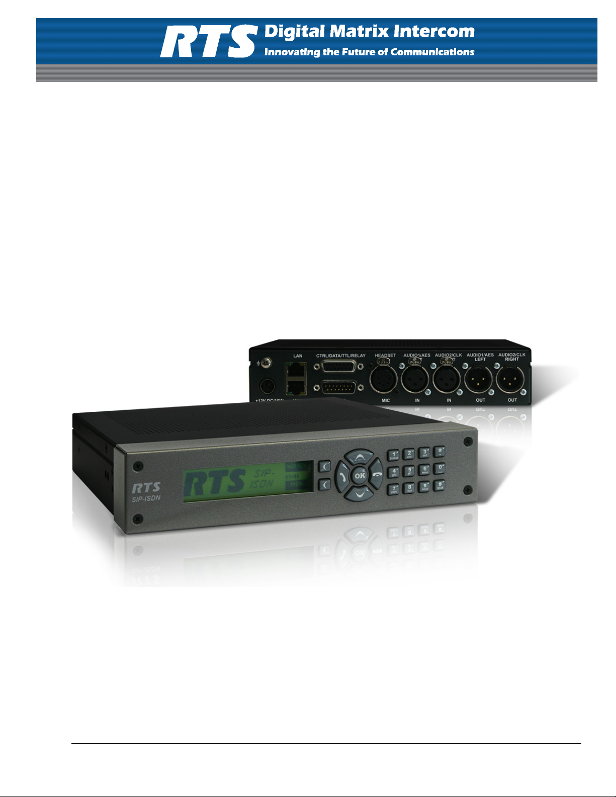
1CONSTRUCTION
The functions of the RTS SIP-ISDN are implemented in a single unit. The system is designed for mounting in a half 19" rack (1 U).
Optionally, a RTS SIP-ISDN DUAL 19“ Mounting Kit is available for the installation
of two RTS SIP-ISDN Systems next to each other.
FIG. 1 FRONT VIEW: RTS SIP-ISDN DUAL ISDN AUDIO CODEC
11
Page 12

12
Page 13
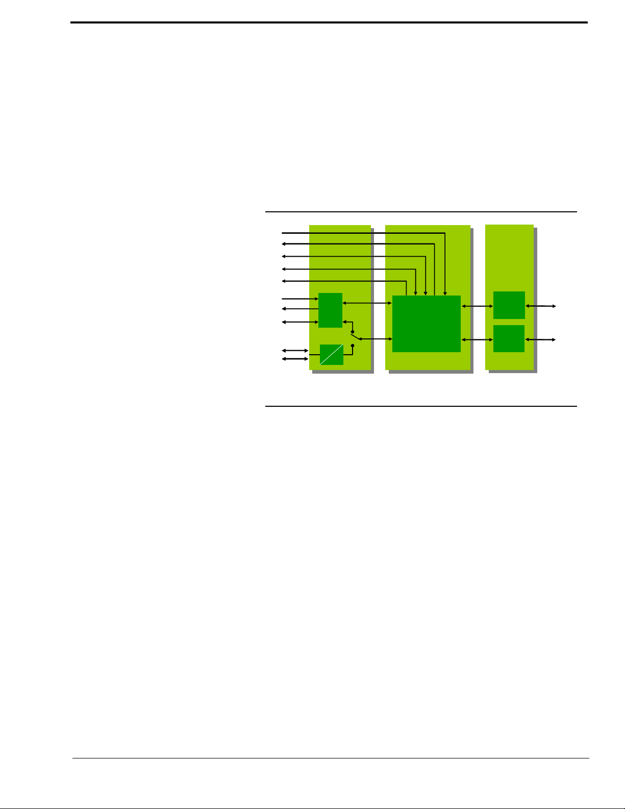
2 SYSTEM DESCRIPTION
ISDN (BRI )
Channel 1
Channel 2
Channel 1/
Channel 2
ANALOGU E
AES/EBU
CLK In
CLK Out
SRC
Input/
Output
DSP
• G.711 Codec
• G.722 Codec
• Ma nageme nt
2 Relays
6 TTL I/O
RS232
Display
Keypad
Control
A
D
ISDN
Controll er
LAN
LAN
Contr oller
ISDN (BRI )
Channel 1
Channel 2
Channel 1/
Channel 2
ANALOGU E
AES/EBU
CLK In
CLK Out
SRC
Input/
Output
DSP
• G.711 Codec
• G.722 Codec
• Ma nageme nt
2 Relays
6 TTL I/O
RS232
Display
Keypad
Control
A
D
ISDN
Controll er
LAN
LAN
Contr oller
The functional elements of the system are pictured in Fig. 2.
FIG. 2 FUNCTIONAL ELEMENTS RTS SIP-ISDN
2.1 Functionality
The RTS SIP-ISDN System incorporates an ISDN telephone interface and a LAN interface. The complete signal processing is taken over by a digital signal processors. In this
way the following functions are realised:
DSP1:
– G.711 Audio encoding and decoding
– G.722 Audio encoding and decoding
– Signalising management
– Control of the complete system (Keypad, display, relays, TTL, RS232)
Via the Audio channels 1 & 2 the Audio signal is inserted or output analogue or digitally.
If the digital AES/EBU Audio interface is used, two separate Sample Rate Converters are
available for automatic clock synchronisation. For external clocking a clock input and a
clock output are available
The configuration and operation can be primarily carried out via the front keypad and the
illuminated display.
Configuration and control is especially comfortable with the RTS SIP-ISDN Windows
PC Software which is included in delivery and which communicates with the system via
the RS232 or LAN interface.
13
Page 14

The basic operating functions like accepting a call, dropping a connection and establsihing a connection with a preprogrammed number can be carried out via six programmable TTL contacts. Two relays are available for status indication.
Optionally, the system can also be operated separately via the RTS SIP-ISDN Keypad
that can be connected to the RS232 interface.
14
Page 15

3 PUTTING THE RTS SIP-ISDN INTO
!
3.1 Mounting
With its dimensions (W × H × D) of 220 mm × 44,5 mm (1 U) × 220 mm the RTS SIPISDN System can be used either as desktop device or mounted in 19 inch racks. Corre-
sponding 19“ mounting brackets are included in delivery. Optionally, a mounting kit to
install two RTS SIP-ISDN next to each other is available.
When mounting the unit please keep in mind that the bending radius of the cables is always greater than the minimum allowed value.
When the RTS SIP-ISDN Audio Codec is installed, please make sure that there is sufficient ventilation: It is recommended to keep a spacing of ca. 3 cm from the openings. In
general, the ambient temperature of the system should be within the range of +5°C and
+45°C. These thresholds are especially to observe if the system is inserted in a rack. The
system works without ventilation.
OPERATION
TIP
ATTENTION Incorrect ambient temperature and humidity can cause functional deficiencies
3.2 Connection to the mains voltage
The system temperature can be indicated on the display (Menu Status informa-
tion
see CHAPTER A1.4, Page 71))
During operation air humidity must range between 5% and 85%.
Operation outside the threshold values indicated above leads to a loss of warranty
claim.
The system can be operated with mains voltages in the range from 90 V to 253 V via the
external power supply included in delivery. The line frequency can vary from 45 Hz to
65 Hz. The maximum power consumption is 15W. The rack must be earthed according
to the VDE Regulations. The earthing can be carried out via the earthing screw on the
back side of the unit.
The unit does not have a circuit closer and a circuit breaker. After plugging in the external
power supply the system boots within a few seconds. In standby mode the RTS logo is
shown on the display.
15
Page 16
3.3 Earthing of the system
!
Softkeys Navigation
buttons
Establish connection
Accept call
Drop/
Main menu
Keypad for
dialling/ text entry
B channel
shift
Confirm
entry/
Graphical
display
Status window
For EMC reasons an earthing via the earthing screw of the system must be carried out in
either case.
ATTENTION Earthing
A lacking earthing can cause functional deficiencies within the unit.
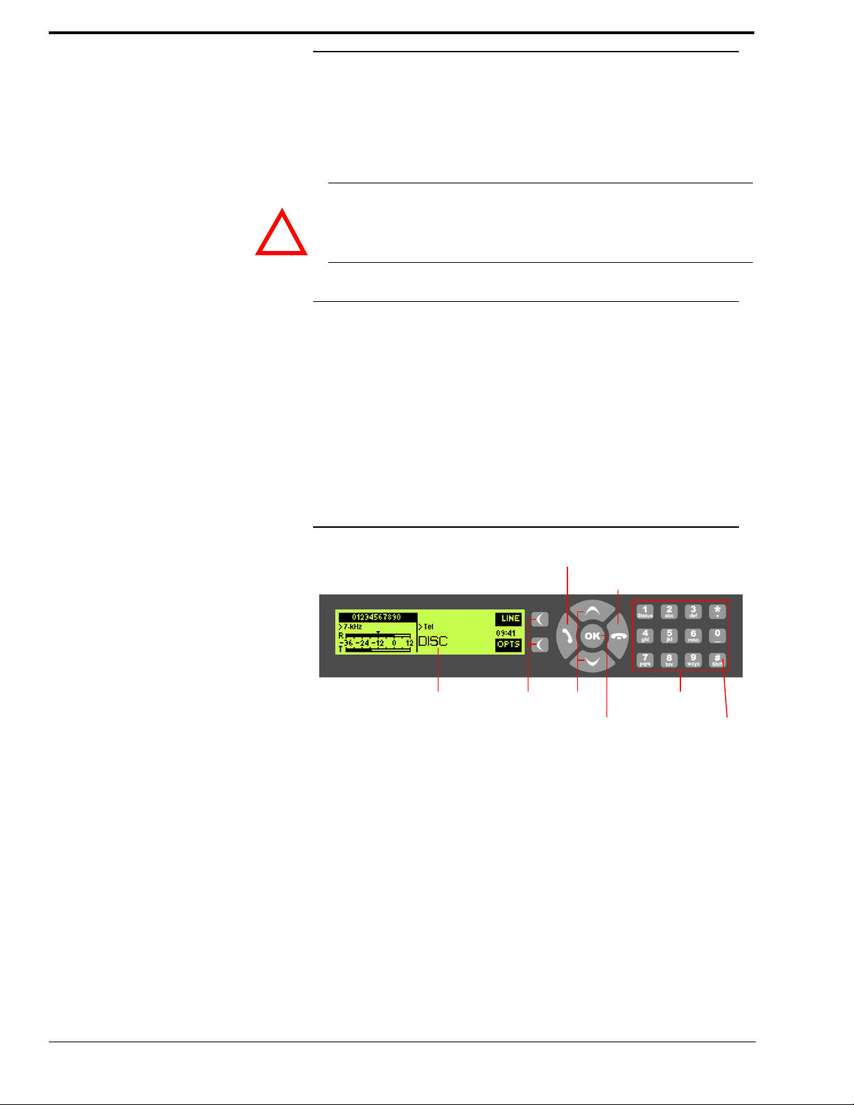
3.4 Operational elements on the front side
The system has an illuminated graphical display with a resolution of 160 x 32 Pixels and
21 operating buttons.
On the right next to the display there are two softkeys whose current functions are indicated on the display. In the middle there are two buttons for navigation (selection upwards/downwards), two buttons for accepting/dropping calls as well as an
The numerical pad supports in addition to the numerics
entries the numerical pad can also be used as normal keypad.
OK button.
0...9 the ’*’ and ’#’ key. For text
The operation is similiar to standard mobile telephones.
FIG. 3 OPERATIONAL ELEMENTS ON THE FRONT SIDE
16
Page 17
3.5 Operating modes of the system
Power supply
interface
ISDN
interface
Analogue Audio 1 (left)/(AES/EBU) Input
Analogue Audio 1 (left)/(AES/EBU) Output
Analogue Audio 2 (right)/(clock) Input
Analogue Audio 2 (right)/(clock) Output
ISDN
interface
ISDN
interface
LAN
interface
Headset/Microphone
Power supply
PC with Option:
RTS SIP-ISDN
Hybrid Keypad
RTS SIP-ISDN
Software
interface
ISDN
interface
REL2
TTL1
TTL2
TTL3
Programmable
TTL Inputs/Outputs
REL1
Programmable
relays
Analogue Audio 1 (left)/(AES/EBU) Input
Analogue Audio 1 (left)/(AES/EBU) Output
Analogue Audio 2 (right)/(clock) Input
Analogue Audio 2 (right)/(clock) Output
2 x transparent
data channels
(RS232 or RS485)
Headset/Microphone
LAN
interface
TTL4
TTL5
TTL6
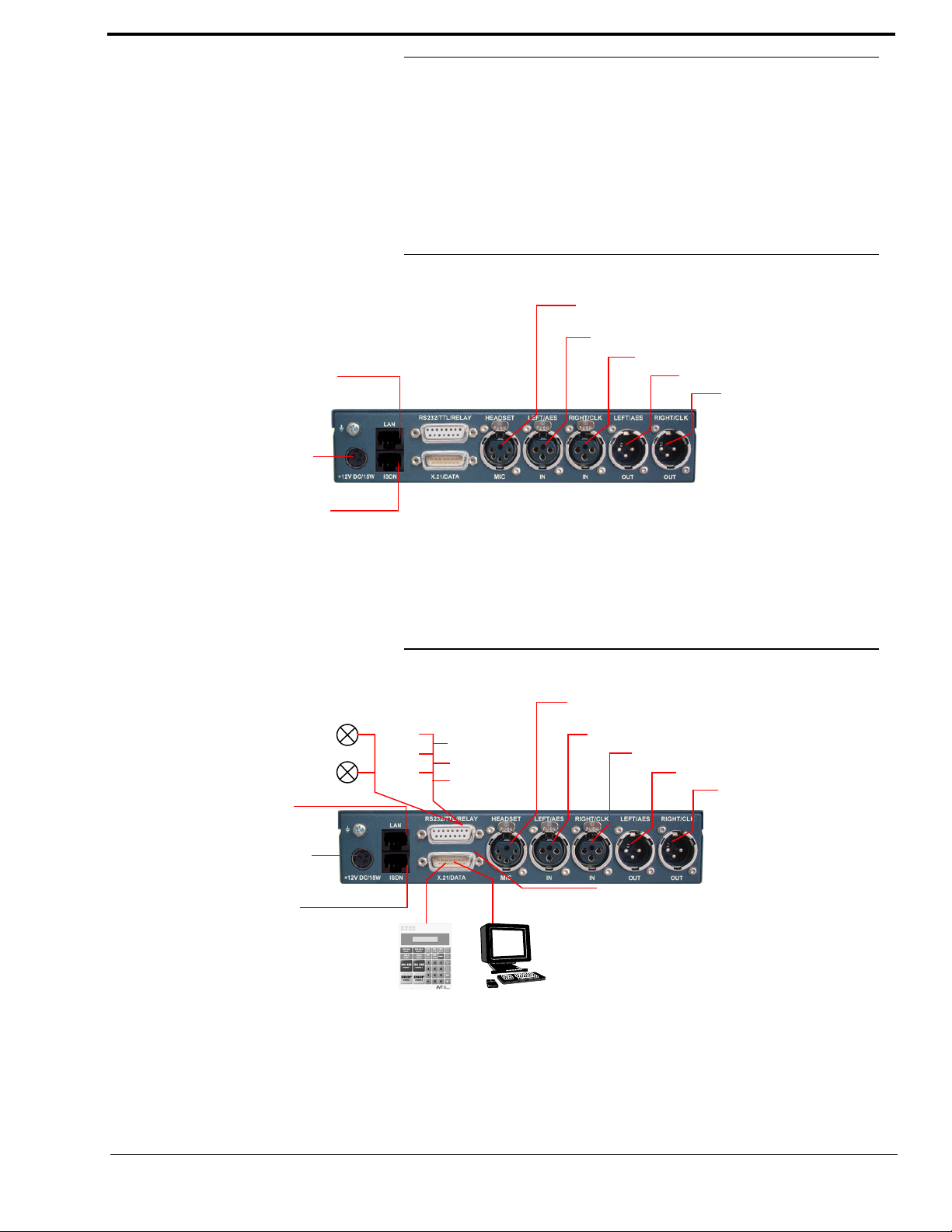
The figures below show the systems in the different operating modes and their wirings.
3.5.1 ISDN operation
In the ISDN operating mode two independent B channels are available which can be used
separately for two transmissions.
FIG. 4 MINIMUM WIRING FOR ISDN OPERATION
The maximum wiring with all options is shown in Fig. 5. Via the RS232 control interface
a RTS SIP-ISDN Keypad and via the LAN interface a PC with RTS SIP-ISDN Software
can be connected as alternative to the operation by the front keypad and display.
FIG. 5 MAXIMUM WIRING FOR ISDN OPERATION
17
Page 18

3.5.2 IP operation
In the IP operation mode the independent 64 kbit/s channels can be realised for two transmissions.
18
Page 19

4 OPERATION VIA DISPLAY AND
Menu reference number
KEYPAD
In this chapter all basic configurations for the operation of the RTS SIP-ISDN system
are explained. An overview of the menu structure you will find in the annex under
CHAPTER A1.
Of course, all configurations can also be comfortably made via the RTS SIP-ISDN Soft-
ware included in delivery.
NOTICE
4.1 Basic configurations
NOTICE
4.1.1 Keypad lock
For the details of most functions please see the PC Software description from
CHAPTER 5.
In the following some specific basic configurations of RTS SIP-ISDN are decribed in
detail.
All menus can be reached directly via a Quick Menu key sequence. For this purpose
each manu item is marked with a cypher in the upper left corner (in the example on
the left it is e. g.
the key sequence
tive menu reference number. Please notice that the menu reference number can
change depending on the configuration.
To avoid that keys are pressed accidentally you can enable a keypad lock. For activation
please press the
the display illumination is turned off immediately.
The keypad lock is deactivated by entering the key sequence
3). To reach a certain menu directly please enter from the main menu
Menu key followed by the
Menu <DIGIT> <DIGIT> whereby <digit> marks the respec-
(star) button. If the keypad lock is enabled
*
Menu
a second time.
*
4.1.2 Setting the Audio interface: Analogue or digital
RTS SIP-ISDN incorporates analogue as well as digital Audio interfaces which you can
adjust separately. The digital AES/EBU interfaces have integrated Sample Rate Con-
verters to adjust the digital Audio source to the transmission clock. Additionally, clock
inputs/outputs are also available. To configure the Audio interface please follow the instructions below:
NOTICE
If you are not in the main menu please press the button first.
19
Page 20

– First press the softkey Menu and select System Settings via the softkey Sel-
ect
.
TIP
– With the use of the
– Please mark the option
and and press again
played.
– Select the desired interface with the help of the cursor keys and and by pres-
sing the softkey
– Confirm your entry by pressing the
– To get back to the main menu please press the button. Now you are asked if
you want to Save settings?. Via the softkey Yes the setting is stored permanently
in the system.
You reach the settings for the Audio input or Audio output via the key sequence:
Select softkey you reach the option Audio Settings.
Audio input or Audio output using the cursor keys
Select. Now the options Analogue and Digital are dis-
Select.
Ok button or the softkey Ok.
Menu 1 1 1 or Menu 1 1 2
20
Page 21

4.2 Working with the RTS SIP-ISDN
In the next chapters basic functions like establishing a connection, dropping a connection, accepting calls etc. are decribed in detail.
NOTICE
4.2.1 Calling a partner
4.2.2 The Status Display - Operation during a connection
TIP
If you are not in the main menu please press the button first.
From the main menu you reach the status window via the
From the main menu just enter the phone number using the keys
the phone number is displayed automatically after entering the first cypher.
With the softkey
The connection is established after the entry of the phone number by pressing the telephone receiver button .
Under the softkey
book see CHAPTER 4.3.2, Page 23) or stored as Quick Dial Number see CHAPTER
4.3.2, Page 23).
After the telephone receiver button is pressed the partner is called and the status window
is displayed automatically.
The status window can always be reached by pressing the OK button.
Delete misentries can be corrected.
Opt. (Options) the entered phone number can be saved in the phone
Ok button.
0...9. The input field for
During a stereo connection the number of the connected B channels is displayed to the
left of the level indication.
In the ISDN operating mode the window is split if two independent connections have
been established.
To switch between the two connections, please press the
selected channel is displayed inversely.
An outgoing call is signalised by
phone book entry is selected) is displayed in the first line.
When the connection is established the level indication for the incoming signal(
and for the outgoing signal(
With the use of the softkey
possible to directly switch to the phone book.
Dialling... . The dialled number (or the name if a
Transmit) is displayed.
Opt. the displayed phone number can be stored and it is also
Shift key (#). The name of the
Receive)
21
Page 22

4.2.3 Dropping a connection
The connection is dropped by pressing the telephone receiver button . If no further
connection exists, the main menu is displayed after a few seconds.
NOTICE
4.2.4 Accepting a call
NOTICE
Please make sure that you have selected the right channel if you want to drop a connection.
If the RTS SIP-ISDN receives a call, it is automatically signalised in the status window
by
Callin.
Additionally, a system ringing tone can be enabled.
The call can be directly accepted with the telephone receiver button .
If you want to reject the call, please press the following telephone receiver button .
22
Page 23

4.3 Comfort Functions
4.3.1 Redialling
You reach the redialling function by pressing again the telephone receiver button for
the line on which no connection currently exists. The recently called partners are displayed in a list. In the input field
partner from the list using the cursor keys and
To call a partner please press again the telephone receiver button .
Search you can search for a certain partner or select a
.
NOTICE
4.3.2 Using the phone book
To enter characters you can use the alphanumeric keypad. You reach the desired character by pressing the respective key several times. To type e.g. a ’
the button ’
To switch between upper and lower case please press the
changes from
The system incorporates a comfortable phone book function. You reach the phone book
from the main menu via the softkey
In the input field Search you can search for a certain partner. As soon as you enter a
character the corresponding phone book entries are filtered out.
Alternatively, you can select a partner from the list using the cursor keys and
By the softkey Opt. (Options) the following functions, which you can select via the
softkey
– New Entry: With the help of this function you create a new phone book entry.
First enter the name and confirm your entry with
Then enter the phone number of the partner and confirm it as well with
5’ twice. Misentries can be corrected with the help of the softkey Delete.
ABC to abc.
Select, are realised:
K’ you need to press
SHIFT key. The display
Names.
.
Ok.
Ok.
TIP
Edit: This function allows you to edit already existing phone book entries.
–
Display: The selected phone book entry is displayed with name and phone number.
–
Delete entry: The selected phone book entry is deleted. For safety reasons you are
–
asked if you really want to delete the entry.
–
Save as Quick Dial: Your 10 most important phone numbers can be programmed
as Quick Dial numbers on the numerical keys ’
the list on which you want to programme the phone number.
To activate a Quick Dial number just press from the main menu the desired Quick
Dial key for at least 3 seconds. The connection to the partner is established automatically.
The phone book functions can also be reached directly via the QuickBook function.
Please press the following key sequence:
Example: Save as Quick Dial - Names Opt. 5
0’ ... ’9’. Please select the key from
Names Opt. <DIGIT>
23
Page 24

4.3.3 Working with Presets
The RTS SIP-ISDN differentiates between System Settings and Operation Set-
tings
.
System Settings are settings that do not change during normal operation like e.g. language, date/time etc. These parameters cannot be saved as Preset since a configuration
is usually only required when the system is put into operation.
Operation Settings like e.g. the line interface, Ringing Tone, etc, need to be reconfigured
depending on the application. To easily recall recurring configurations you can store up
to 10 Presets in the system.
NOTICE
You reach the menu for the Presets by pressing the
key twice and by pressing the softkey
In the input field
acter, the corresponding entries of the Preset list are filtered out.
Alternatively, you can select a Preset from the list using the cursor keys and
If you now press the Ok button, the selected Preset is loaded immediately.
By the softkey
softkey
Select are realised:
– Load: The stored Preset is loaded.
New: With the help of this function you can create a new Preset. All current Opera-
–
tion Settings are stored.
– Save: The currently selected Preset is overwritten with the current Operation Set-
tings. For safety reasons a confirmation is required.
– Delete Preset: The currently selected Preset is deleted. For safety reasons a confir-
mation is required.
If the configuration has changed, you are asked if you want to Save settings? when
you leave the Preset menu. Via the
nently in the system. This Preset is loaded automatically by the system after the unit
is connected to the power supply.
Presets you can search for a certain Preset. As soon as you enter a char-
Opt. (Options) the following functions which you can select via the
Select once as confirmation.
Yes softkey the configuration is stored perma-
Menu softkey once, the cursor
.
24
Page 25

5 WINDOWS PC SOFTWARE
The configuration of the system is particularly comfortable via the Windows PC Software included in delivery.
5.1 Hardware requirements
The PC must meet the following minimum requirements:
– IBM PC AT, IBM PS/2 or 100% compatible
– Pentium Processor (> 500 MHz) recommended
– Windows 2000/XP
– ca. 600 kilobyte available RAM
– 5 MB available hard disk space
– Screen resolution with 800 x 600 Pixels
– at least one available serial interface RS-232
– Microsoft, IBM PS/2 or 100% software compatible mouse
5.2 Installing the Windows PC Software
Please insert the CD included in delivery in your CD-ROM drive. The software automatically starts your Internet browser. Possible safety warnings can be ignored for the moment. Please press under Install Software the RTS SIP-ISDN button. Subsequently,
the setup program is executed.
Alternatively, you can install the software directly from the CD. You will find the installation file setup.exe in the folder Software\RTS SIP-ISDN on the CD.
Please follow the instructions of the installation routine.
After the installation the software can be started by clicking on the RTS SIP-ISDN.
Please connect your PC via a serial 1:1 cable (only Pin 2 and Pin 3 are used, Pin
5=ground) with the system.
The standard COM Port settings are: PC (19200 Baud)
25
Page 26
Operation via Windows PC software
Menu bar
Calling or
Caller information
(Name, Number)
accepting a call
Drop a call
Phone book
Redialling
Operating mode
Received level Transmitting level
Input field for
calling number
In the following chapters all functions of the PC software are described in detail.
5.3 The RTS SIP-ISDN main window
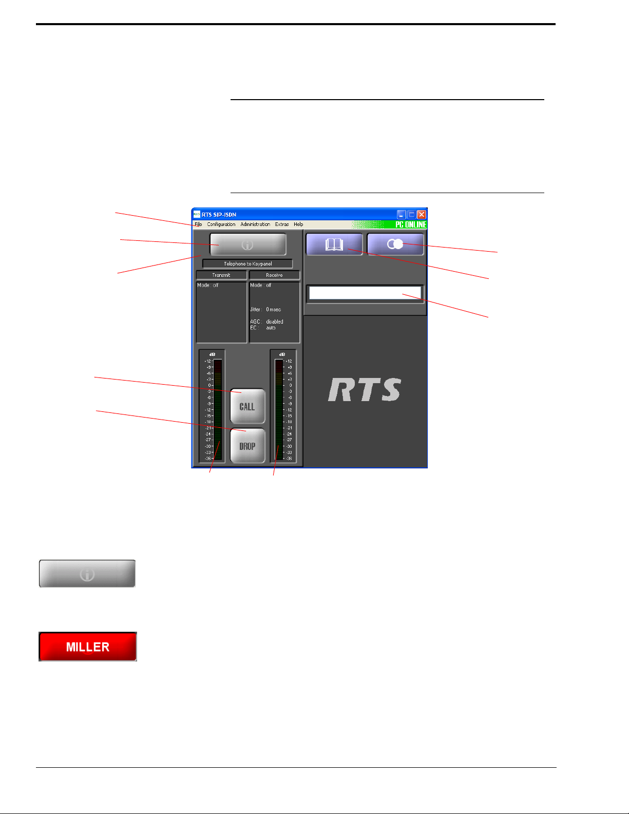
After starting the RTS SIP-ISDN software, the main window is displayed automatically.
The connection status between the PC and the system is displayed in the upper right corner of the window.
FIG. 6 RTS SIP-ISDN MAIN WINDOW
26
5.3.1 Operating elements
5.3.1.1 Info button
On the INFO button the information about the caller is shown. If transmitted the phone
number of the caller is displayed. If additionally a phone book entry is available, the
caller’s name is displayed.
During Call In or Call Out the INFO button will be displayed in yellow, during a connection the INFO button is red.
By pressing the INFO key the phone book (see CHAPTER 5.3.1.3) is opened and the
entry can be edited immediately.
Page 27
5.3.1.2 Level indicators
!
The outgoing transmitting level as well as the received level of the callers are displayed
via separate level meters.
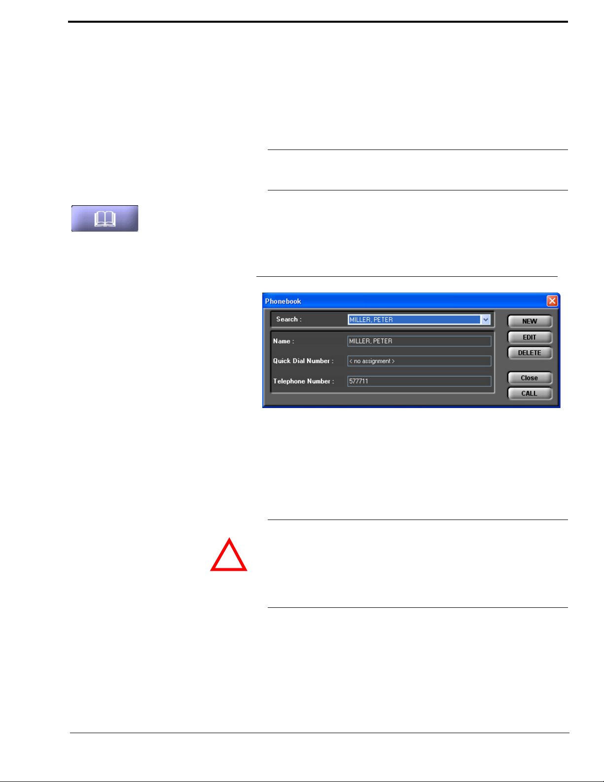
5.3.1.3 Telephone book
With the use of the phone book button telephone numbers can be saved comfortably in
the phone book.
NOTICE
The phone book is stored in the RTS SIP-ISDN system and not in the PC. Via the
menu File
from a data file or exported as data file (see CHAPTER 5.4.1).
To open the phone book, please press the phone book button.
Via the Search field you can search directly for a name in the phone book using the drop
down list. When an entry is selected, Name, Telephone Number and if assigned
Quick Dial Number of the entry are displayed.
FIG. 7 TELEPHONE BOOK
→ Phone Book → Import/Export a phone book can be imported
• To create a new entry, please press the button NEW. Now, a window is displayed
where you can enter the Name and the Telephone Number of the new entry and
if desired assign a Quick Dial Number.
OK button.
ATTENTION The name entered in the phone book has to be unique. Identical names are not per-
mitted. The best way to provide a clear identification is to enter the last name and the
first name.
If the name already exists, an error message is displayed asking you if you want to
overwrite the already existing name. If you want to overwrite the old entry and save
your new entry, select OK. If you do not want to overwrite the old entry, select Can-
cel.
•Via the EDIT button, an already existing entry can be edited. Please select the entry
you want to edit from the drop down list (SEARCH) and press the EDIT button.
Now, a window is displayed where you can change the details of the entry. To save
your changes, press the OK button.
To save the new entry, please click on the
27
Page 28
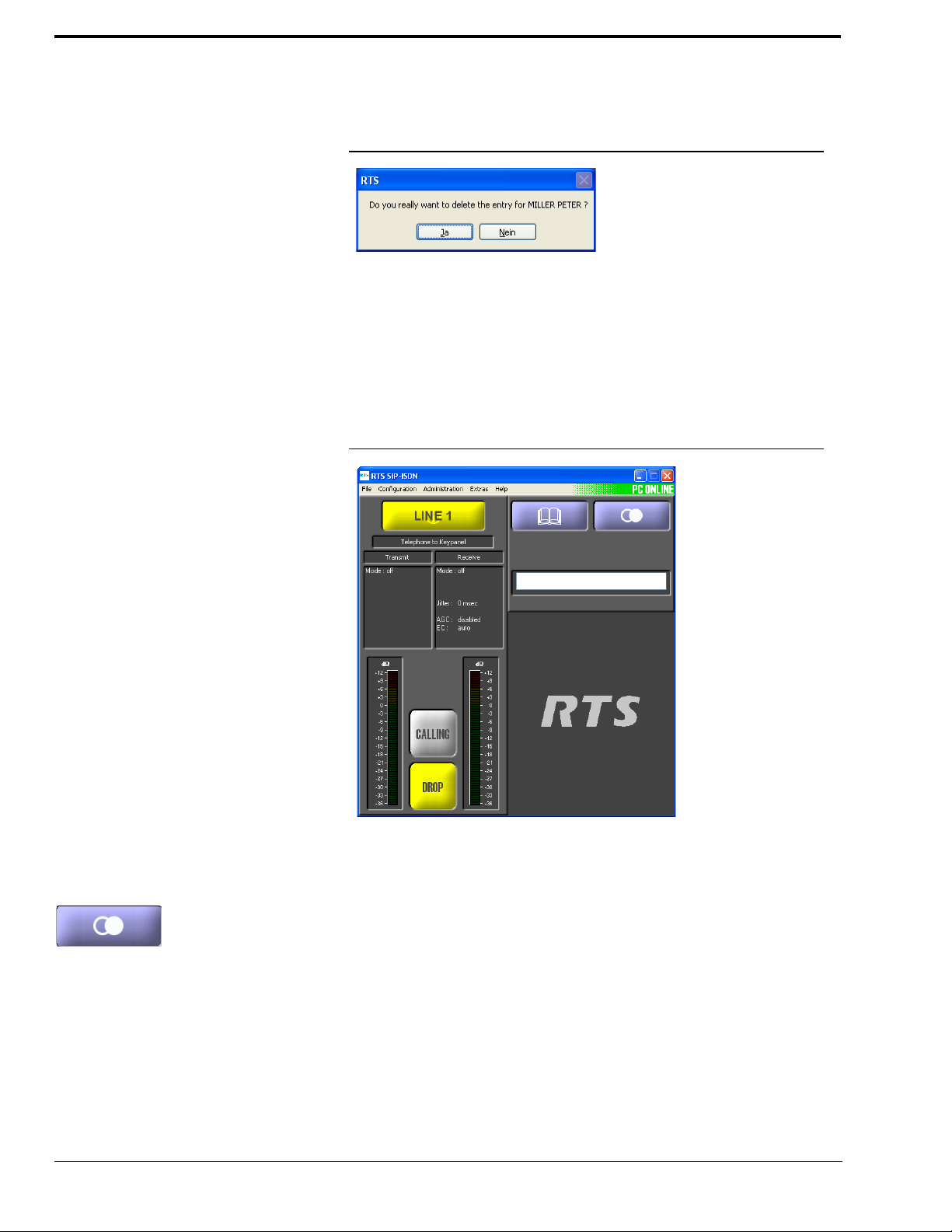
• With the use of the DELETE button you can delete an entry from the telephone book.
Please select the entry you want to delete from the drop down list (SEARCH) and
press DELETE. For safety reasons you have to confirm that you really want to delete
the entry.
FIG. 8 SAFETY CONFIRMATION TO DELETE A PHONE BOOK ENTRY
• Via the CLOSE button you can exit the telephone book.
• If you want to call an entry directly from the telephone book, you can use the CALL
button. Please select the entry you want to call from the drop down list (SEARCH)
and press the CALL button. The telephone book window is closed and the system
calls the selected entry. In the main window of the PC software the CALL button
changes to CALLING and the DROP button is blinking in yellow.
FIG. 9 CALLING A PHONE BOOK ENTRY
28
5.3.1.4 Redialling
If you click on the Redialling button, the ten most recently dialled numbers are displayed
and can be selected for redialling. To call one of the displayed numbers, you only need
to click on it with the left mouse key.
Page 29
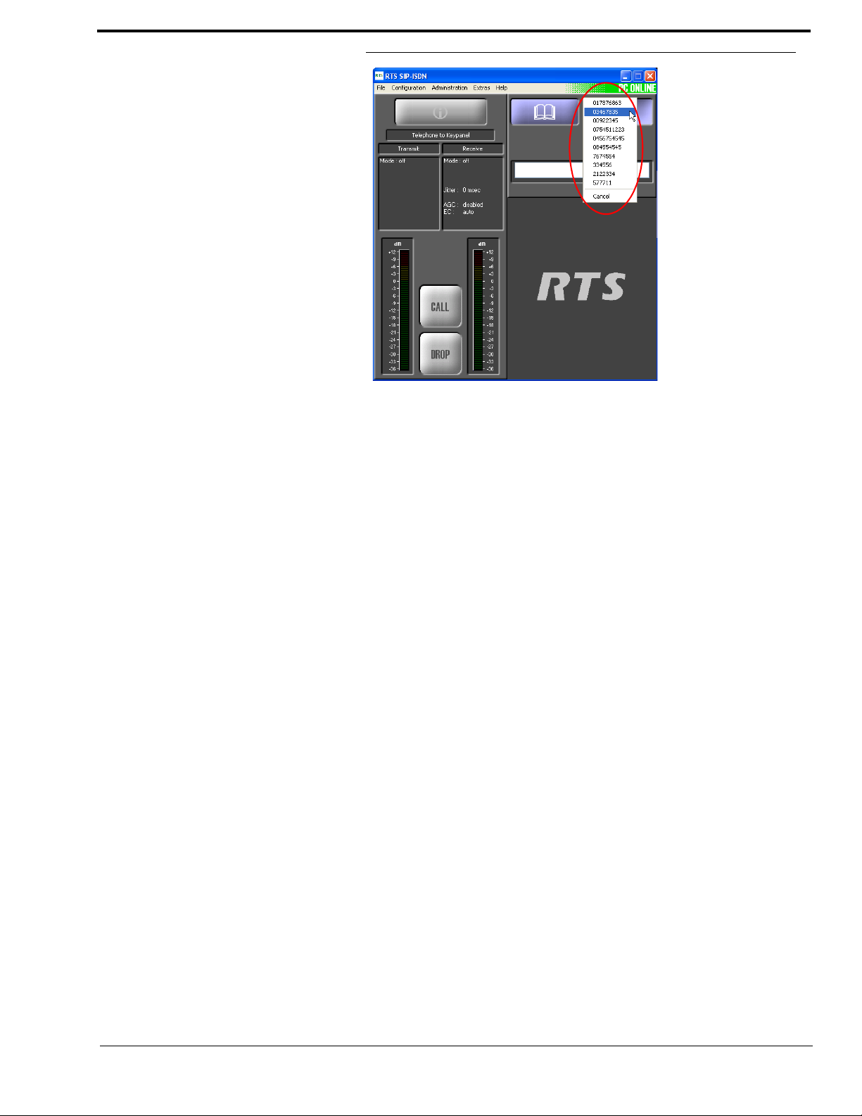
FIG. 10 TEN MOST RECENTLY DIALLED NUMBERS
29
Page 30
5.4 Menu File
Under File you will find the function for importing and exporting phone book files and
the exit.
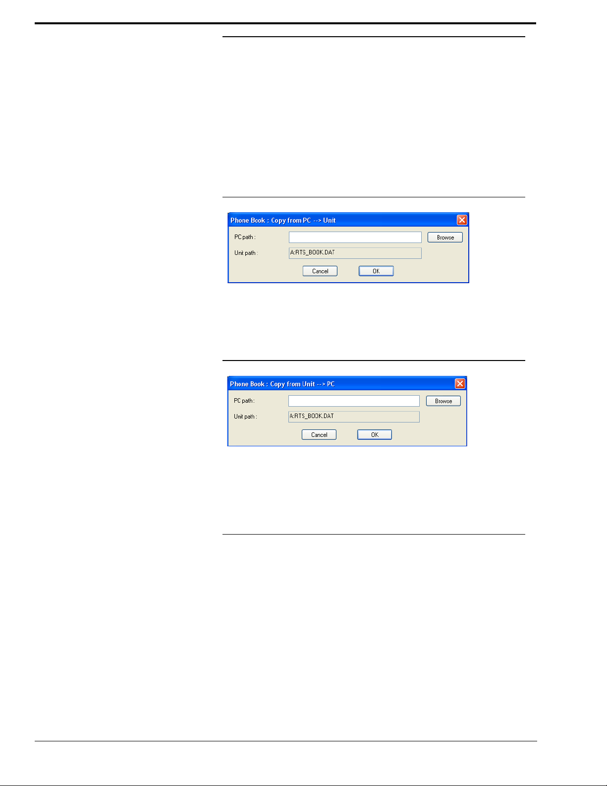
5.4.1 Submenu Phone Book
To import a phone book from PC please select File
With Browse you can select the phone book which is to be imported. The file extension
of a phone book is ‘.csv‘. Such a file can be edited with e.g. MS
FIG. 11 IMPORTING A PHONE BOOK
To export a phone book, please select File → Phone Book → Export. The file is
saved with ‘.csv‘ extension. The desired directory in which the file is saved can be selected via Browse.
FIG. 12 EXPORTING A PHONE BOOK
→ Phone Book → Import.
®
EXCEL.
30
5.4.2 Submenu Exit
Via the submenu Exit you can exit the RTS SIP-ISDN software.
5.5 Menu Configuration
5.5.1 Submenu COM Port
The system is connected to a PC via the serial RS232 interface and a 1:1 connecting cable
or via tha LAN interface. The settings of the PC COM Port can be adjusted under Con-
figuration
→ COM Port.
Page 31

FIG. 13 RS232 PARAMETER OF THE COM PORT
Please select under Port the interface of your PC with which the RTS SIP-ISDN is connected.
Under Mode the desired operating mode can be chosen:
– PC & Keypad (9600 Baud): To connect a keypad or a PC
– PC (19200 Baud): To connect a PC
– PC (38400 Baud): To connect a PC
– PC (57600 Baud): To connect a PC
– PC (115200 Baud): To connect a PC
All further parameters like Data Bits, Parity and Stop Bits cannot be configured.
5.5.1.1 Control via RS232
If you want to use the RS232 interface, connect the serial RS232 interface (via enclosed
adapting cable DATA1/PC) with a 1:1 connecting cable with your PC.
Please select now under Interface
Port of your PC, which is connected with the system and under Mode the desired baud
rate (standard: 38400 Baud).
FIG. 14 RS232 INTERFACE PARAMETER
→ RS232. Under Parameter → Port the COM-
31
Page 32

5.5.1.2 Control via LAN
For controlling the system via the LAN interface please select Interface
UDP.
FIG. 15 LAN INTERFACE PARAMETER
Under Parameter → Interface edit <Default>. If there should be more than one net-
work interface card in your PC, select the desired one.
5.5.2 Submenu RTS SIP-ISDN
Via the submenu RTS SIP-ISDN the system can be configured completely.
→ LAN/
After changing a setting the following options are available:
•With OK the configuration window is closed and all settings made are saved.
• The function Apply Now allows to save the current settings without closing the configuration window.
• Cancel cancels all settings made.
32
Page 33

5.5.2.1 Configuration
5.5.2.1.1 Operating Modes
FIG. 16 SELECTION OF OPERATING MODE
Connection 1/ Connection 2
Under Operating Modes the operating modes for both channels (Connection 1 and
Connection 2) can be selected. The available options are:
– 1: Telephone to Keypanel
– 2: Keypanel to Matrix
– 3: Matrix to Matrix
– 4: Matrix to Matrix with Trunkmaster
– 5: ELA Mode
• The option Automatic Mode can only be activated for Mode 1: Telephone to
Keypanel or Mode 3: Matrix to Matrix. If the box is checked, the system will de-
tect if Mode 1 or Mode 3 is needed when a connection is established and select the
required operating mode automatically.
•If Mode 1: Telephone to Keypanel or Mode 3: Matrix to Matrix is selected, you
need to select which RS 485 address is to be used.
Data Interface
The settings for the Data Interface (Mode and Baudrate) can be adjusted if Mode 4:
Matrix to Matrix with Trunkmaster is selected. If Mode 1, 2, 3 or 5 is selected, the
settings under Data Interface cannot be changed.
33
Page 34

5.5.2.1.2 Line Interface
The option Line Interface allows the configuration of the Line interface.
FIG. 17 LINE INTERFACE LAN/SIP
General
•With Line Mode you can select the line mode. Two options are possible:
– ISDN: The system is connected to an ISDN network and two independent chan-
nels are available.
– LAN/SIP: The system is connected to a LAN network with SIP server.
• The option Enable Auto Answer allows the system to automatically accept inco-
ming calls.
• If the Enable Auto Answer is selected, the acceptance can be delayed for 0 to 31
seconds with the use of the controller Delay. The default setting is 0 s.
• If the option Enable System Ringing Tone is activated, the system signals incoming calls with a ringing tone.
34
Page 35

ISDN Parameters
!
FIG. 18 LINE INTERFACE ISDN
Prefix Number
NOTE
ATTEN TION You must enter the external prefix number at any case if you operate the system with
The following settings are only necessary if the system is used with a PABX.
• Under Length of Internal Telephone Numbers you indicate the length of your
internal telephone numbers. In this way, the prefix number is dialled automatically, if
the length of the calling number is bigger than the length indicated here. If you do not
want to use this functionality, or if you use the system with a main connection, please
enter a 0 into the respective field.
Examples: Length of internal telephone numbers: 3
Calling number entered: 130
It is dialled: 130
Length of internal calling numbers: 3
Calling number entered: 5271130
It is dialled: 0 5271130
• Under External Prefix Number you enter the external prefix number which you
must dial to get an outside line. In most cases it is 0.
a PABX since only in this case the system waits for a dial tone. Without an external
prefix number, the calling number is transmitted too fast and the connection cannot
be established.
• Some PABXs transmit the calling number with prefix number to the system. If you
want to transfer the displayed calling number without the prefix number directly into
the telephone book, you can enable the function Skip prefix number on inco-
ming call.
35
Page 36

MSN (Multiple Subscriber Number)
Usually the entry of a MSN is not necessary. However, if several systems (e.g. RTS
ISDN 2005, fax, telephone, etc.) are operated with one ISDN interface, you can allocate
a certain calling number to a certain system by entering a MSN.
Example: A telephone, an ISDN PC card and a RTS SIP-ISDN unit are operated with
one ISDN interface. From your provider you got the following MSN: 5271011, 5271012,
5271013.
Without a MSN entry, all three units respond to the incoming call - no matter which of
the three calling numbers was dialled. However, if a different MSN is allocated to each
unit, the system only responds if exactly this MSN was dialled by the caller. If you enter
e.g. the MSN ’5271013’ for the RTS SIP-ISDN, the system will only signal the call, if
the caller dialled ’5271013’. However, precondition for this example is that you enter the
same MSN for MSN 1 and MSN 2.
Enter the desired MSN under MSN 1 respectively MSN 2. Of course, the same MSN
can be allocated for both B channels. Please notice that a MSN is always entered without
area code.
NOTE
NOTE
Some PABX require the entry of a MSN since otherwise no operation is possible.
If you cannot establish a connection between the RTS SIP-ISDN system and a partner system, but you are sure that the ISDN line is working, you should try if it works
after entering a MSN.
Dial In Numbers (Access Protection)
Via the Dial In Numbers function an access protection for the system can be activated.
All calling numbers which are entered in the list can establish a connection with the system. Please enter Name and Number for each list entry.
Please consider that only chyphers which are actually entered are analysed, i.e. if you
only enter „130“, all participants with a calling number which ends with „123“ are
allowed to call the system.
The total character length of all entered telephone numbers must not be higher than
127. With an average length of a telephone number of 12 characters about 10 calling
numbers can be saved.
For this functionality the calling number of the participants in the list needs to be
transmitted (CLIP
1. Calling Line Identification Presentation
1
function).
36
•With Add you can create a new entry
FIG. 19 CREATING A NEW ENTRY
Page 37

• The button Edit allows to edit already existing entries
•With Delete an entry can be deleted. For safety reasons you must confirm that you
really want to delete the entry
5.5.2.1.3 Configuration of the SIP Parameters for LAN/SIP Line interface
FIG. 20 SIP PARAMETER
For using Audio over IP it is necessary to set the parameters for SIP. Please enable SIP
Registration.
To get a connection with the SIP server please enter your User Name, SIP Password, and
the IP address of the SIP Server.
If a firewall is installed „Use STUN server“ needs to be enabled and the IP address of the
STUN server needs to be entered.
5.5.2.1.4 Signal Processing
Under Signal Processing the caller signal can be optimised by adjusting the Automatic
Gain Control, the Echo Canceller and the Expander.
37
Page 38

FIG. 21 SIGNAL PROCESSING
Line Settings
• A separate Automatic Gain Control can be switched on or off for each caller line.
To configure the Automatic Gain Control (AGC) for Connection 1 or Con-
nection 2, please select the desired line and click on the Edit button. A window is
opened in which you can adjust the settings.
FIG. 22 CONFIGURATION AGC AND ECHO CANCELLER
Via the button Set AGC on/off for all lines you can set the Automatic Gain Con-
trol on/off for all lines with a single mouse click.
38
Page 39

• For each caller line, a separate Echo Canceller is available which can be set ON, OFF
or is activated automatically (AUTO) if required.
NOTICE
In general, the use of the Echo Canceller is recommended. When a subscriber calls
with an analogue telephone, a line echo is produced which can interfere with the incoming signal. Digital telephones (e.g. ISDN or mobile phones) do not produce these
line echoes. In this case an Echo Canceller would worsen the incoming signal. For
this reason the system sends a short test tone when a connection is established (only
in the AUTO mode) and detects the level of the echo. If a certain threshold value is
not exceeded, the Echo Canceller is set off because the use of a digital phone on the
counterpart is anticipated. If the level is too high, the Echo Canceller is set on automatically.
But: Echo Cancellers can only suppress echoes if the delay of the signal lies within a
certain scope. Telephone connections via satellite have such a long delay that the
Echo Canceller cannot work properly anymore.
To configure the Echo Canceller, please select the desired line with your mouse and
press the button Edit, which opens the configuration window.
To generally set the Echo Canceller off select Off.
If you always want to have the Echo Canceller activated, select Always ON. In
this case, no test tone to detect the echo is sent.
If the option Auto is selected, the Echo Canceller is switched on or switched off dynamically. The system sends a short test tone to determine if Echo Cancelling is required or not.
Via the button Set EC on/off/auto for all lines you can select the same operating
mode of the Echo Canceller for all lines.
Automatic Gain Control (AGC) Settings/Expander
The functioning of the AGC can be optimised via several parameters.
• Threshold: The AGC does not start before the signal exceeds the threshold value
selected under Threshold. The default setting is -30 dBu.
• Level: The level selected corresponds with the desired average level. Please consider
sufficient head room. The default setting is -12 dBu.
• Speed: Depending on the desired speed of the level adjustment (Slow, Medium or
Fast) the setting of the AGC speed can be configured here. The faster the AGC must
work the more noticeable are the inconsistencies. If the selected speed is too slow, the
caller signal is too low or too loud on average. The default setting is Medium.
•An Expander turns down the caller signal automatically, if its level falls below a
certain threshold value. The aim is to completely filter out background noises of callers who are not currently speaking.The Expander is activated by checking the respective box.
• With the use of the Default Settings button, the default settings indicated above are
selected and the Expander is enabled.
39
Page 40

5.5.2.2 Basic Settings
NOTE
5.5.2.2.1 General
All settings made under Basic Settings cannot be saved as Configuration.
FIG. 23 BASIC SETTINGS (GENERAL)
NOTE
NOTE
Display Language
• Currently the languages English and German are supported as display languages.
Key Tone
• To active the key tone for the system, please select the check box Enabled.
Display
The Display has a backlight. Under Backlight you can set it on permanently if you select On. If Auto off is selected, the backlight is automatically turned off 60 seconds after
the last keystroke. The backlight can be activated again by pressing any key (e.g.
Please notice that if the key lock is enabled, the backlight is not activated before you
press the key sequence
• With the slide controller Contrast you can set the desired contrast for the display
within the range of -16 ... 15. The default setting is
To use the following functions a user or administrator password must be entered under Login (siehe ABSCHNITT 5.5.2.4).
MENU
.
*
0
.
OK)
40
Page 41

• If the option Switch Off Display on Password Key Lock is selected, the display
is automatically switched off after 60 seconds after logging out. Any keystroke acti-
vates the display. Dialling is possible.
• If the function Activate Password Key Lock on Password Logout is enabled,
the key lock is automatically activated 60 seconds after logging out. Next to the clock
a key symbol is displayed. In addition to the configuration lock by entering a password under Login, dialling via the numerical keypad is no longer possible.
RS232 Interface
If you want to operate the system with a PC, you need to configure the data rate of the
interface. The following five baud rates are available: PC & Keypad (9600, None),
PC (19200, None), PC (38400, None), PC (57600, None), PC (115200, None).
The default setting is PC (38400, None).
NOTE
5.5.2.2.2 Audio Interface
The RTS SIP-ISDN Keypad supports only a baudrate of 9600 Baud. Therefore, if
you use the keypads, always select PC & Keypad (9600, None). This baudrate can
also be selected if a PC is used.
If a PC is connected via the RS232 interface, the selected baudrate must be identical
with the baudrate of the COM interface.
RTS SIP-ISDN supports analogue as well as optionally digital AES/EBU Audio interfaces. If the digital interface is used, separate Sample Rate Converters for input and output are available which supersedes external adjustments for different digital sources.
FIG. 24 CONFIGURATION OF THE AUDIO INTERFACES
Audio Interface
• The operating modes analogue or digital can be individually adjusted for the Audio Input and the Audio Output.
41
Page 42

AES/EBU Interface
• If you select the option digital for the output, the configuration for the AES/EBU
Interface is displayed. Under Clock Source of digital output the following set-
tings are available:
– Internal: The AES/EBU output clock is adapted to the internal system clock.
– External: The AES/EBU output clock is adapted to the external clock which is
supplied by the Audio 2/CLK IN interface. The clock frequency of the supplied
clock needs to be 48-kHz.
– Recovered: The AES/EBU output clock is recovered from the digital input sig-
nal of the Audio 1/AES IN interface. This configuration should be selected if you
use the digital input of the system. In this way, a synchronous working of the
transmission chain is ensured.
NOTE
5.5.2.2.3 Relay/TTL
An AES/EBU input always works with recovered clock. Therefore, only a configuration of the output is required.
For clock synchronisation with other systems, you can use the clock output Audio 2/
CLK OUT. The clock frequency of the output clock is 48-kHz.
Main Nominal Level
• If you select the analogue mode for input or output, the corresponding slide controller
is displayed to set the nominal Audio level of the XLR Audio interfaces (Main No-
minal Level). The main nominal level can be adjusted separately for the input (Le-
vel In) and for the output (Level Out) within a range of -3 ... +9 dBu in steps of 1-
dB. The head room is 6 dB. If you want to have the maximum level of 15 dBu for the
system, you need to set 9 dBu as main nominal level. The default setting is 0 dBu.
The RTS SIP-ISDN System provides six GPIO Pins (TTL) which can be individually
programmed as input or output. Additionally, two Relays are available.
The functionality of a TTL Pin - Input or Output can be selected using the drop down
list for Direction.
The following description is valid for all six configuration windows TTL1 (Pin 9),
TTL2 (Pin 10), TTL3 (Pin 11), TTL 4 (Pin 12), TTL 5 (Pin 13) and TTL 6 (Pin
14).
42
Page 43

TTL Pin as input
FIG. 25 TTL PIN AS INPUT
If you use a TTL Pin as Input, you
can configured two different func-
1
tions
when the edges change:
• Positive edge: The event is
triggered when the voltage at the
TTL Pin changes from 0V
to+5V.
• Negative edge: The event is triggered when the voltage at the TTL Pin changes
from +5V to 0V.
The following Function Codes can be selected:
– - (Not used): No function, the Pin is not used. This option is to be selected for re-
mote control via the function Output
– Call Number: Using this function, a call can be accepted or a connection can be
established with a certain Number. Under Line you select which channel (1 or
2) is to be used to establish the connection.
– Call Number (level triggered): Identical function like above, however, only
the level is analysed and not the edge.
– Disconnect: By enabling this function a connection on the indicated line (1 or
2) can be disconnected.
→ Remote TTL Input (see page?).
– Set Information Base Entry: Special function for projects.
– String Command: Special function for projects.
1. Except function code Call Number (level triggered), if this code is selected only one edge can be used.
43
Page 44

– Load Configuration: Via this function a configuration which you must indicate
!
under Configuration can be loaded.
Example:
Using TTL1 a call is to be accepted on line 1. After the call is finished, it is to be
disconnected also using TTL1.
Programming:
Positive edge:
Function Code: Call Number
Line: 1
Number: -
Negative edge:
Function Code: Disconnect
Line: 1
TTL Pin as Output
ATTENTION Please consider that the maximum switching current is 10 mA and the maximale
switching voltage is 5V per TTL output.
FIG. 26 TTL PIN AS OUTPUT
If a TTL Pin is configured as Output, the event is signalled when the voltage at the TTL
Pin changes from 0V to +5V.
44
Under Positive edge you can select the following Function Codes:
– Fixed Low (0V): The TTL Pin is fixed to 0V.
Page 45

– Fixed High (5V): The TTL Pin is fixed to +5V.
!
– PC Controlled: Special function for projects.
– Connection State: Via this function you can signal the connection state of a line.
Please select the desired connection state under Connection State. The following
options are available:
– Disconnect
– Call Out
– Call In
– Connect
– Call Setup
Under Line you can select for which line you want to signal the connection state. In
addition to line 1 and line 2 you can monitor the connection status of both lines if you
select all. As soon as one of the two lines meets the criteria, the signal is triggered at
the TTL Pin.
– Information Base Entry: Special function for projects.
– System Alarm Pending: This function signals a pending system alarm (siehe
ABSCHNITT 5.7.1).
– Remote TTL Input: If this function is selected, you can signal the TTL status of the
selected Remote TTL input Pin (1, 2, 3) of the remote system. In this way. remote
systems can be controlled remotely or information about the hardware status can be
transmitted. On the remote side the function Input
med for the corresponding TTL Pin to enable remote control. If a TTL Pin of the remote side is configured as output, the status of the Pin is transmitted.
→ - (not used) must be program-
– Remote PC Controlled: Special function for projects.
Relay
ATTENTION Please consider that the maximum switching current is 200 mA and the maximum
switching voltage is 48V per relay output.
The following description is valid for both configuration windows Relay 1 (Pin 6+7)
and Relay 2 (Pin 8+15).
45
Page 46

FIG. 27 RELAY
The functions for programming the relays are identical with the function codes for the
TTL output. The following options (Function Codes) are available:
– Always open: The relay contacts are always open.
– Always closed: The relay contacts are always closed.
All further function codes are explained under TTL Pin as Output (see page 44).
5.5.2.2.4 Remote Control
The RTS SIP-ISDN Remote Control Software is available as optional software. Via this
software you can have remote access to the RTS SIP-ISDN System with the help of any
PC with an integrated ISDN card. The software option is protected by a USB Dongle. A
highlight is the integrated ISDN S
channel protocol (see page 60).
Monitor, which allows a detailed analysis of the D
0
46
Page 47

FIG. 28 REMOTE CONTROL
General
NOTICE
NOTICE
• To allow remote control of your system, please select the option Enable Remote
Control.
• If you want to protect your system with a password from unauthorised access, you
can activate the option Enable ISDN Password Check. Under Password you
must enter your password and confirm it under Confirm Password.
There is no differentiation between upper and lower case for the password entry.
Authorized Numbers
• If you only want to allow ISDN remote access/control via certain telephone numbers
(e.g. support), you can enter these numbers together with a name under Authorized
Numbers.
To add an entry, please click on Add.
If you want to change already existing entries, select the desired entry with your
mouse and click on Edit.
To delete a number, select the desired number and click on Delete. for safety reasons
you have to confirm that you really want to delete the entry.
If no numbers are entered under Authorized Numbers, remote access is possible via
any telephone number. In this case, you should use a password to protect your system
from unauthorised use.
5.5.2.2.5 Quick Dial
t.b.d.
47
Page 48

5.5.2.2.6 LAN
For setting the LAN interface please enter the requested data such as IP address and Default Gateway.
FIG. 29 LAN INTERFACE
48
Page 49

5.5.2.3 Date and Time
!
The option Date and Time allows to select a date and time for the system.
FIG. 30 DATE AND TIME
There are two ways of setting date and time of the system.
• If you want to transmit the date and the time of the PC which is connected with the
RTS SIP-ISDN system, please click on Transmit PC Time.
• If you want to set date and time manually, please select the desired date and time under User Defined Time and click on Transmit User Defined Time.
5.5.2.4 Login
To protect the system from reconfiguration, two password levels with different user
rights are available
ATTEN TION The entered passwords are stored in the system. Take care in entering a password. If
you forgot your password, the system can only be unlocked by the TELEX Service.
• Under USER you can assign the User Password. For safety reasons the password
needs to be confirmed under Confirm Password.
• Under ADMINISTRATOR you can assign the Administrator Password. For safety
reasons the password needs to be confirmed under Confirm Password.
NOTE
It is not differentiated between upper and lower case when a password is enterd.
49
Page 50

FIG. 31 LOGIN
As soon as you assigned a password, a Login window is automatically displayed when
you click on a menu which is protected by the password. Please enter the user or the administrator password there.
FIG. 32 PASSWORD LOGIN
The user and administrator rights are allocated in the following way:
(1) Only Administrator Password configured: Password is required for changes in
the configuration. Immediately available menus:
– Configuration
– Extras
(2) Only User Password configured: The password is always required. Subse-
quently, all menus are available. Immediately available menus:
– Extras
(3) User and Administrator Password configured. A password is always required.
– User Password is entered:
Under Configuration → Configuration → Login only the USER Pass-
word can be changed.
→ System Monitor
→ System Monitor
→ Configurations→ „Name of the Configuration“
50
With Configuration
loaded.
Immediately available menus:
– Extras
→ System Monitor
→ Configurations the desired Configuration can be
Page 51

Administrator Password is entered: All menus are available.
NOTE
5.5.3 Submenu Configurations
5.5.3.1 Manage Configurations
Please notice also the effect on the configurations menu, if a password is assigned.
Via the submenu configurations you reach the preset management. You can store, load
and edit configuration presets.
Under Configuration
manage your already existing configuration presets and create new configurations.
FIG. 33 MANAGE CONFIGURATIONS
→ Confgurations → Manage Configurations you can
NOTE
In the list all already existing configurations are displayed.
With the button New you can create a new configuration. It has no effects on the current
system configuration which is neither changed nor loaded. First, please assign a suitable
name.
FIG. 34 CREATE NEW CONFIGURATION
The length of the name must not exceed 8 characters. Special characters and space
characters are not allowed. Please make sure that the same name is not assigned to
several configurations, otherwise an alarm message will be displayed asking you if
you want to delete the already existing configuration.
Subsequently, the menu for editing the Configuration is displayed. The current system
configuration is always taken as basis for a new Configuration preset. This basis can
be adapted as desired. The following settings can be stored in a configuration:
51
Page 52

– Operating Modes (see page 33)
– Line Interface (see page 34)
– Signal Processing (see page 37)
FIG. 35 EDIT PRESET
By pressing the Edit button the configuration selected from the list can be edited. The
current configuration of the system is not changed or loaded when a configuration preset
is edited.
Via the Delete button you can delete the configuration selected from the list. For safety
reasons a confirmation is required.
FIG. 36 CONFIRMATION TO DELETE A CONFIGURATION
To activate a configuration selected from the list, please press the Select button. For
safety reasons a confirmation is required.
FIG. 37 CONFIRMATION TO SELECT A CONFIGURATION
5.5.3.2 Select a Configuration
52
All Configuration presets are displayed under Configuration
→ Configurations
→ „Name of Configuration“ and can be selected by clicking on the relevant confi-
guration preset.
Page 53

FIG. 38 SELECT A CONFIGURATION
For safety reasons a confirmation is required.
FIG. 39 CONFIRMATION TO SELECT A CONFIGURATION
53
Page 54

5.6 Menu Administration
5.6.1 Submenu Registration
Via the submenu Registration you can check the enabled firmware options.
FIG. 40 REGISTRATION
Under Hardware the system name is displayed (RTS SIP-ISDN). Under the Main tab
all relevant information for identification like the Subject Number, Factory Num-
ber, Year of production and Hardware Version can be found.
Under Features all available software options are displayed.
54
Page 55

5.6.2 Submenu File System
!!!
!
By selecting the submenu File System the file directory of the system (similar to the
harddisk of a PC) is displayed.
ATTEN TION Please do not carry out any actions under File System unless our support asked you
to. All user import/export functions can be found under the menu File (see CHAPTER 5.4).
ABB. 41 SUBMENU FILE SYSTEM
Via the Delete File button the currently selected file is deleted.
ATTEN TION Do not delete a file unless our service told you to delete the file. Otherwise a malfunc-
tion of the system can occur.
The Copy PC -> Unit button allows you to copy a file from a PC to the system.
ATTENTION Please use only the Software Download function (see CHAPTER 5.6.4) or the im-
port function under the File menu (siehe ABSCHNITT 5.4) to copy file to the systems.
The Copy Unit -> PC button allows you to copy a file from the system to the connected
PC.
ATTENTION Please use only the export function under the File menu (siehe ABSCHNITT 5.4) to
copy files to a PC.
55
Page 56

5.6.3 Submenu System Panel
The System Panel is only for service purposes. Please only enter commands in the
prompt, if our support asked you to do so.
FIG. 42 SUBMENU SYSTEM PANEL
56
Page 57

5.6.4 Submenu Software Download
The Firmware required for the RTS SIP-ISDN system is always included in the PC software. Via the Software Download the firmware can be comfortably loaded on the system.
Via the Browse button you select the firmware file. The file is always stored in the directory in which you installed the RTS SIP-ISDN application. The standard installation
directory is:
C:\Programmes\RTS SIP-ISDN
The name of the firmware file is „rts.ssw“.
FIG. 43 SUBMENU SOFTWARE DOWNLOAD
Please press the Start button to load the firmware on your system. The Progress bar
shows the status of the download. After about three minutes the download will be finished. If the download had been successful, a message is displayed. After a confirmation
the system executes a reset.
NOTE
5.6.5 Submenu Set Factory Settings
If a download had been faulty, you can simply switch off the unit and then switch it
on again. The new software is only written in the flash memory, if a download had
been successful. Otherwise the old firmware is maintained.
Via the submenu Factory Settings all settings are reset to the factory settings.
For safety reasons a confirmation is required.
57
Page 58

FIG. 44 CONFIRMATION REQUEST TO SET FACTORY SETTINGS
NOTE
The telephone book and the Configuration presets are not deleted.
58
Page 59

5.7 Menu Extras
Alarm counter
5.7.1 Submenu System Monitor
Via the menu System Monitor you receive all information about the status of the system.
FIG. 45 SYSTEM MONITOR
NOTE
• Under System alarms all possible system alarms are displayed. A red LED signals
a currently existing alarm. It is also displayed how often the alarm occured since the
unit has been switched on.
If an alarm occurs several times or for a longer period of time, please disconnect the
system from electricity. If you switch on the unit and the alarm occurs again, there is
probably a hardware defect.
The following alarms are signalled:
– LCA (Logic Cell Array): The communication with a programmed component
is faulty.
– TIME KEEPER: The communication with the integrated time keeper is faulty.
– A/D D/A Converter 1: The communication with the first ADDA Converter is
faulty.
– A/D D/A Converter 2: The communication with the second ADDA Converter
is faulty.
– Temperature Sensor: The communication with the temperature sensor is
faulty.
– FLASH EPROM: The communication with the non-volantile memory is faulty.
Settings cannot be stored or read.
– MAIN EEPROM: The communication with the non-volantile memory is faulty.
Settings cannot be stored or read.
59
Page 60

– Overheated: The systems sets this alarms if the system temperature is higher
than 57°C. Please disconnect the system from electricity or cool down the ambient air temperature.
TIP
You can also configure a system alarm as relay output (see page 45).
• Under Application alarms all possible application alarms are displayed. A red
LED signals a currently existing alarm. It is also displayed how often the alarm occurred since the unit has been switched on.
– H.221 Framing: If the ITU-T J.52 inband signalling is used, faulty H.221
frames are displayed and filed.
– If the optional, digital Audio output is selected, but no digital Audio signal is con-
nected to AUDIO1/AES/LEFT IN, the AES3 Framing alarm occurs.
– The actual system temperature can be found under System Temperature. The
temperature is measured in °C. A normal system temperature lies around
30...40°C.
– Under DSP Load the load of the system is displayed. A normal DSP load is
30...60%.
• Under System Logfile a detailed ISDN logfile can be generated.
– ISDN Layer 1: (Physical Layer): All messages which concern the physical acti-
vation/deactivation of the ISDN interface are saved in Layer 1.
– ISDN Layer 2: (Data Link Layer): The Data Link Layer is responsible for pack-
ing the data from the physical layer into frames. It can detect and/or correct errors
and manages the data flow between nodes. This layer is only to be activated for
logging if problems are supposed to occur. Please notice that if it is activated
every 8 seconds an entry is generated and therefore the memory is filled very fast.
NOTE
– ISDN Layer 3 (Network Layer): The Network Layer handles the routing of the
data (sending it in the right direction to the right destination on outgoing transmissions and receiving incoming transmissions at the packet level). For the logfile,
this layer is the most important one since all connection data is recorded here.
– The logfile can be deleted by pressing the Delete File button. For safety reasons
a confirmation is required.
The system stores all messages of the activated ISDN Layer. The internal memory capacity is 128-kByte
The data can be analysed using the optional RTS SIP-ISDN Remote Control &
ISDN Monitoring Software (see CHAPTER 6). Our support is also able to read the
data remotely. If you experience problems with your ISDN connection, please activate the desired ISDN Layer of the system logfile enabling us to analyse them.
1
. The data is stored in a cyclic way.
60
1. An entry of the ISDN protocol is about 15 Byte on average.
Page 61

5.8 Menu Help
5.8.1 Submenu RTS SIP-ISDN
In the About RTS SIP-ISDN dialogue you can find the software versions of the PC
Software (PC Version) and of the system (Firmware Version). Furthermore, our con-
tact information is displayed.
FIG. 46 SUBMENU ABOUT RTS ISDN 2005
61
Page 62

62
Page 63

6 OPTION: REMOTE CONTROL
SOFTWARE
The fee-based RTS SIP-ISDN Remote Control & ISDN Monitor Plug-In Software enables you to access the RTS SIP-ISDN System from any PC with an integrated ISDN
card. A local RTS SIP-ISDN System is not required. The software option is protected by
an USB Dongle. A special highlight is the integrated ISDN S
detailed analysis of the D channel- locally as well as remotely.
Monitor which allows a
0
63
Page 64

6.1 The integrated S0 Monitor
The integrated S0 Monitor allows a detailed analysis of the D channel protocol.
FIG. 47 S0 MONITOR USER
• The D channel protocol can be analysed Online or via the System Log File stored
in the system. You can select the desired operating mode under Navigation. Stop
stops the current logging.
• The option Display switches between the User, Layer 2 and Layer 3 display. The
User view displays a summary of the most important information. Of course, for experts the options Layer 2 and Layer 3 are also informative.
• Errors in the log file are displayed red-shaded. Via the button Go to Error the next
error in the log file is displayed.
• The button Reset resets the display window.
• With the use of the Export key the log file can be exported in the currently selected
readout as RTF (Rich Text Format). This file can be read with MS WORD for instance.
• Via the Open button a previously stored log file can be opened and analysed offline.
• By pressing the button Save the current log file is stored as binary file.
• In the line HEX the binary data of the currently selected log file line is displayed in
hexadecimal form.
64
Page 65

• Using Filter you can filter the log file for certain criteria. S0 selects the ISDN inter-
face of the system. For the RTS SIP-ISDN this value must always be „0“ respectively
be empty since the system incorporates only one ISDN interface.
Using the filter CR (Call Reference) you can display all available entries for a transaction. Additionally, the colour in which the entries are displayed is changed for each
new Call Reference.
FIG. 48 S0 MONITOR LAYER 2
65
Page 66

FIG. 49 S0 MONITOR LAYER 3
66
Page 67

A1 MENU STRUCTURE
On the following pages you will find the complete menu structure if you select
ENGLISH as menu language
From the main menu you reach the phone book directly via the softkey Names. With the
use of the softkey
The configuration menu is divided in five submenus:
– System Settings
– Operation Settings
– Presets
Menu you get to the configuration of the system.
NOTICE
– Status information
– Login
Please note that depending on the selected operating mode some menu items are not
displayed.
If you use an Administrator and/or User Password, the display looks as it is described below:
(1) Only Administrator Password configured: The password must be entered for
changes to the basic settings and operation settings only. Immediately available
menus:
– Presets
– Status information
–Login
(2) Only User Password configured (instead of Menu, Login is displayed): The
password must always be entered. Subsequently, all menus are available.
(3) User and Administrator Password configured (instead of
played):
– User Password is entered: The menus
Presets, Status information and
Menu Login is dis-
Login are available
NOTICE
– Administrator Password is entered: Alle menus are available.
There is no differentiation between upper and lower case for the password entry.
67
Page 68

A1.1 System Settings
68
Page 69

A1.2 Operation Settingss
69
Page 70

A1.3 Presets
70
Page 71

A1.4 Status Information
Menu
Menu
4 - Statu s Information
4 - Status Information
3 - System Te mperature
3 - System Temperature
1 - Versi on
1 - Versi on
2 - AES/EBU Input Status
2 - AES/EBU Input Status
4 - Warm Re start
4 - Warm Res tart
Login
Presets
System Se ttings
Operation Settings
RTS SIP-I SDN Application
Software Version
RTS SIP-IS DN Application
Software Version
AES/EBU In put Status
AES/EBU I nput Status
System Temperature
in degree Celsius
System Temperature
in degre e Celsius
Menu
Menu
4 - Statu s Information
4 - Status Information
3 - System Te mperature
3 - System Temperature
1 - Versi on
1 - Versi on
2 - AES/EBU Input Status
2 - AES/EBU Input Status
4 - Warm Re start
4 - Warm Res tart
Login
Presets
System Se ttings
Operation Settings
RTS SIP-I SDN Application
Software Version
RTS SIP-IS DN Application
Software Version
AES/EBU In put Status
AES/EBU I nput Status
System Temperature
in degree Celsius
System Temperature
in degre e Celsius
71
Page 72

A1.5 Login
72
Page 73

A1.6 Names
73
Page 74

74
Page 75

A2.1 Keypanel Cable DB9
1
2
6
8
7
3
4
5
9
2
3
5
2
3
1
2
3
1
DB-9 (female)
To Matrix
Data Matrix
Audio From
Matrix
Audio To
Matrix
XLR (female)
XLR (male)
DB-9 (male)
To data 1 or data 2
adap ter cable
+
+
+
+
+
+
-
-
-
-
-
-
To RTS SIP-ISDN
To RTS SIP-ISDN
1
2
6
8
7
3
4
5
9
2
3
5
2
3
1
2
3
1
DB-9 (female)
To Matrix
Data Matrix
Audio From
Matrix
Audio To
Matrix
XLR (female)
XLR (male)
DB-9 (male)
To data 1 or data 2
adap ter cable
+
+
+
+
+
+
-
-
-
-
-
-
To RTS SIP-ISDN
To RTS SIP-ISDN
FIG. 50 KEYPANEL CABLE DB9
A2 RTS SIP-ISDN CABLES
75
Page 76

A2.2 Matrix Cable DB9
1
2
6
8
7
3
4
5
9
2
3
5
2
3
1
2
3
1
DB-9 (female)
To Matrix
Data Matrix
Audio From
Matrix
Audio To
Matrix
XLR (female)
XLR (male)
DB-9 (male)
To data 1 or data 2
adap ter cable
+
+
+
+
+
+
-
-
-
-
-
-
To RTS SIP-ISDN
To RTS SIP-ISDN
1
2
6
8
7
3
4
5
9
2
3
5
2
3
1
2
3
1
DB-9 (female)
To Matrix
Data Matrix
Audio From
Matrix
Audio To
Matrix
XLR (female)
XLR (male)
DB-9 (male)
To data 1 or data 2
adap ter cable
+
+
+
+
+
+
-
-
-
-
-
-
To RTS SIP-ISDN
To RTS SIP-ISDN
6
1
2
5
3
4
2
3
5
2
3
1
2
3
1
RJ12 (male)
To Matrix
Data Matrix
Audio From
Matrix
Audio To
Matrix
DB-9 (male)
XLR (male)
XLR (female)
+
+
+
+
+
-
-
-
+
-
-
To data 1 or data 2
adapt er c able
To RTS SIP-ISDN
To RTS SIP-ISDN
6
1
2
5
3
4
2
3
5
2
3
1
2
3
1
RJ12 (male)
To Matrix
Data Matrix
Audio From
Matrix
Audio To
Matrix
DB-9 (male)
XLR (male)
XLR (female)
+
+
+
+
+
-
-
-
+
-
-
To data 1 or data 2
adapt er c able
To RTS SIP-ISDN
To RTS SIP-ISDN
FIG. 51 MATRIX CABLE DB9
76
A2.3 Matrix Cable RJ12
FIG. 52 MATRIX CABLE RJ12
Page 77

A2.4 Data & Control Adapter Cable
77
Page 78

78
Page 79

A3 CABLING OF RTS SIP-ISDN
S
0
ISDN
Matrix
Keypanel
RS485/Audio Cable
RS485/Audio Cable
Keypanel
Adapter Cab le
Matrix Audio/Control Cable
DB9 or RJ12 or RJ45
Matrix Audio/Control Cable
DB9 or RJ12 or RJ45
Telephone
Telephone
PC
LAN
S
0
ISDNISDN
Matrix
Keypanel
RS485/Audio Cable
RS485/Audio Cable
Keypanel
Adapter Cab le
Matrix Audio/Control Cable
DB9 or RJ12 or RJ45
Matrix Audio/Control Cable
DB9 or RJ12 or RJ45
Telephone
Telephone
PC
LAN
A3.1 Cabling Mode 1: Telephone to Keypanel
FIG. 53 CABLING MODE 1
79
Page 80

A3.2 Cabling Mode 2: Keypanel to Matrix
S
0
ISDN
Matrix
Adapte r Cable
Matrix Audio/Control Cable
DB9 or RJ12 or RJ45
Matrix Audio/Control Cable
DB9 or RJ12 or RJ45
PC
S
0
Keypane l
Keypan el
Adapter Cable
Keypanel Audio/Control Cable
DB9
Keypanel Audio/Control Cable
DB9
PC
LANLAN
S
0
ISDNISDN
Matrix
Adapte r Cable
Matrix Audio/Control Cable
DB9 or RJ12 or RJ45
Matrix Audio/Control Cable
DB9 or RJ12 or RJ45
PC
S
0
Keypane l
Keypan el
Adapter Cable
Keypanel Audio/Control Cable
DB9
Keypanel Audio/Control Cable
DB9
PC
LANLAN
S
0
ISDN
Matrix
Matrix Audio Cable
DB9 or RJ12 or RJ45
Matrix Audio Cable
DB9 or RJ12 or RJ45
PC
S
0
PC
Keypan el
Matrix Audio Cable
DB9 or R J12 or RJ 45
Matrix Audio Cable
DB9 or RJ12 or RJ45
RS485/
Audi o Cabl e
Matrix
Keypanel
RS485/
Au dio C ab le
LAN LAN
S
0
ISDNISDN
Matrix
Matrix Audio Cable
DB9 or RJ12 or RJ45
Matrix Audio Cable
DB9 or RJ12 or RJ45
PC
S
0
PC
Keypan el
Matrix Audio Cable
DB9 or R J12 or RJ 45
Matrix Audio Cable
DB9 or RJ12 or RJ45
RS485/
Audi o Cabl e
Matrix
Keypanel
RS485/
Au dio C ab le
LAN LAN
FIG. 54 CABLING MODE 2
A3.3 Cabling Mode 3: Matrix to Matrix
FIG. 55 CABLING MODE 3
80
Page 81

A3.4 Cabling Mode 4: Matrix to Matrix with Trunkmaster
S
0
ISDN
Matrix A
Matrix Audio Cable
DB9 or RJ12 or RJ45
Matrix Audio Cable
DB9 or RJ12 or RJ45
PC
S
0
PC
Matrix B
Matrix Audio Cable
DB9 or RJ12 or RJ45
Matrix Audio Cable
DB9 or RJ12 or RJ45
Adapter Cable
Adapter Ca ble
Trun kmaster
RS485
RS485
Matrix C
Matrix D
RS232
RS485
RS485
LAN LAN
S
0
ISDNIS DN
Matrix A
Matrix Audio Cable
DB9 or RJ12 or RJ45
Matrix Audio Cable
DB9 or RJ12 or RJ45
PC
S
0
PC
Matrix B
Matrix Audio Cable
DB9 or RJ12 or RJ45
Matrix Audio Cable
DB9 or RJ12 or RJ45
Adapter Cable
Adapter Ca ble
Trun kmaster
RS485
RS485
Matrix C
Matrix D
RS232
RS485
RS485
LAN LAN
FIG. 56 CABLING MODE 4
81
Page 82

82
Page 83

A4 TROUBLE SHOOTING
TAB. 1 TROUBLE SHOOTING
Problem Possible cause
The Echo Canceller is not working. If you switch callers via a Call-In Center to the hybrid the Echo Can-
celler is possibly adjusted incorrectly. Enable the Echo Canceller permanently (see ???). Please notice that echoes of more than 32 ms
cannot be filtered out anymore.
83
Page 84

84
Page 85

A5 INTERFACES
The interfaces of the system are pictured in Fig. 57.
FIG. 57 REAR VIEW OF THE RTS SIP-ISDN AUDIO CODEC
All interfaces are described below.
85
Page 86

A5.1 Line interface
181
8
A5.1.1 S0 ISDN interface
This interface supports two B channels in ISDN lines with EURO ISDN (DSS-1) protoco
TAB. 2 PIN ASSIGNMENT: S0 INTERFACE (LINE ISDN)
Socket: Western (8-pole) RJ45
Pin Signal Electrical characteristics
1 not used Recommendation: I.430
2 not used
3 TX a Data out a
4 RX a Data in a
5 RX b Data in b
6 TX b Data out b
7 not used
8 not used
A5.1.2 LAN interface
Data rate: B channel: 2x64 kbit/s
D channel: 16 kbit/s
This interface supports the SIP protocol for building up two IP connections.
TAB. 3 PIN ASSIGNMENT: LAN INTERFACE
Socket: Western (8-pole) RJ45
Pin Signal Electrical characteristics
1 TX+ Data out + Recommendation: IEEE 802.3/Ethernet
2 TX- Data out -
3 RX+ Data in +
4 not used
5 not used
6 RX- Data in -
7 not used
8 not used
Data rrate (automatical): 10BaseT (10-Mbit/s)
100BaseTX (100-MBit/s)
Recommended: CAT5
Maximum cable length: 100m
86
Page 87

A5.2 Control and data interfaces
18
915
A5.2.1 CTRL/DATA/TTL/Relay interface
The CTRL/DATA interface is used for the configuration and operation of the RTS SIPISDN System via a PC. To connect a PC you need a 1:1 connecting cable in which Pin
2 and Pin 3 are not crossed. Furthermore, Pin 5 GND must be connected.
Additionally, two further data interfaces for transparent data transmission are implemented by this interface. The two interfaces can be independently configured by software
either as RS485 or as RS232 interface.
NOTE
Please note that the function - input or output - of the Pins RXD1/2 and TXD1/2 are
determined by the interface type DCE or DTE. The labelling of the Pin is always
RXD for Pin 2 and TXD for Pin 3.
For both data interfaces RXD serves always as receive path and TDX serves always
as transmit path.
TAB. 4 PIN ASSIGNMENT: CTRL/DATA/TTL/RELAY INTERFACE
Socket: SUB-D 15 pole
Pin Signal Direction Electrical characteristics
1 RXD2
2 RXD1
3 TXD1d RS232/RS485 Data (b)
4 TXD2d. RS232/RS485 Data (b) input/E-A
5 GND
6 RELAY 1 (A) output
7 RELAY 1 (B) output
8 RELAY 2 (A) output
9 TTL1 input/output
10 TTL2 input/output
11 TTL3 input/output
12 TTL4 input/output
13 TTL5 input/output
14 TTL6 input/output
15 RELAY 2 (B) output
a
RS232/RS485 Data (a)
a.
RS232/RS485 Data (a) output/E-A
output/E-A
input/E-A
b
PC interfaceRS232:
b.
Type (Pin 2, 3): DCE
Level: V.24
b.
Data rate: max. 115200 Baud
Range: max. 15 m
b.
Protocol: 1 start bit
RS232/RS485 data interface:
Level: V.24 (RS232)
Data rate: max. 115200 Baud
Range: max 15m (RS232)
Protocol: 1 start bit
TTL interface:
Capacity of the TTL outputs:
Maximum voltage: 5V
Maximum current: 10mA
Relay interface:
Capacity of the relays:
Maximum voltage: 48V
Maximum current: 200mA
c
8 data bit
1 stop bit
V.11 (RS485)
max. 100 m (RS485)
8 data bit
1/2 stop bit
Parity adjustable
a. ATTENTION: on this Pin the RTS SIP-ISDN transmits data
b. E-A: input and output at RS485 (bus interface)
c. DCE = Data Communication Equipment
d. ATTENTION: on this Pin the RTS SIP-ISDN receives data
87
Page 88

A5.3 Audio interfaces
Push
12
3
2
1
3
Push
12
3
2
1
3
The system incorporates analogue and digital AES/EBU Audio interfaces. For switching
you can use display and keypad or the PC software.
A5.3.1 Analogue Audio interface
TAB. 5 PIN ASSIGNMENT: ANALOGUE INPUT (AUDIO 1/2 IN)
Socket: 3-pole XLR
Pin Signal Elektrical characteristics
1 GND Input level: adjustable -3 .... +9 dBu
2 AUDIO IN a
3 AUDIO IN b
TAB. 6 PIN ASSIGNMENT: ANALOGUE OUTPUT (AUDIO 1/2 OUT)
Connector: 3-pole XLR
Pin Signal Elektrical characteristics
1 GND Output level: adjustable -3 .... +9 dBu
2 AUDIO OUT a
3 AUDIO OUT b
Impedance: > 25 kΩ
Head room: 6 dB
Impedance: < 50 Ω
Head room: 6 dB
A5.3.2 Digital AES/EBU Audio interface
The RTS SIP-ISDN System incorporates two digital inputs/outputs which are physically
one AES/EBU interface. The input as well as the output has its own sample rate converter providing that a digital source with 32, 44.1 or 48-kHz can be connected directly.
For external clocking (48-kHz only) the word clock input or output may be used.
TAB. 7 PIN ASSIGNMENT: DIGITAL INPUT (AES IN)
Socket: 3-pole XLR
Pin Signal Electrical characteristics
1 GND IEC-958
2 AUDIO IN a
3 AUDIO IN b
TAB. 8 PIN ASSIGNMENT: DIGITAL OUTPUT (AES OUT)
Connector: 3-pole XLR
Pin Signal Elektrical characteristics
1 GND IEC-958
2 AUDIO OUT a
3 AUDIO OUT b
88
Page 89

TAB. 9 PIN ASSIGNMENT: CLOCK INPUT (CLK IN)
Push
12
3
2
1
3
Socket: 3-pole XLR
Pin Signal Elektrical characteristics
1 GND TTL
2CLOCK IN
3 not used
TAB. 10 PIN ASSIGNMENT: CLOCK OUTPUT (CLK OUT)
Connector: 3-pole XLR
Pin Signal Electrical characteristics
1 GND TTL
2 CLOCK OUT
3 not used
89
Page 90

A5.4 Power supply interface
1
3
2
The power supply is connected via an external power supply.
TAB. 11 PIN ASSIGNMENT: POWER SUPPLY
Socket: KYCO KPJ-S3
Pin Signal Elektrical characteristics
1 GND Voltage: +12V
2 +12V
3 not used
Power: max. 15W
90
Page 91

A6 TECHNICAL DATA RTS SIP-ISDN
91
Page 92

92
Page 93

A7 TECHNICAL DATA RTS SIP-ISDN
to RTS SIP-ISDN
to power supply
to Keypad
(1)
(2)
(3)
142
5
3
6
A7.1 Keypad
FIG. 58 CONNECTING CABLE MAGIC SYSTEM - KEYPAD
KEYPAD
Matrix: 8 x 6
32 keys
(4 quad keys, 4 double keys, 24singlekeys)
Protocol:
9600 Baud
no parity
Connection to external power supply (1):
6-pole Mini-DIN connector
Assignment:
Pin 3: GND (ground)
Pin 4: +5V
Connection to RTS SIP-ISDN (2):
9-pole SUB-D connector
93
Page 94

Connection to Keypad (3):
5
96
1
231
6
4
5
A7.2 LCD Display
Assignment:
Pin 2 RXD
Pin 3 TXD
Pin 5 GND (ground)
8-pol. MINI DIN connector
Assignment:
Pin 2: clock
Pin 3: +5V
Pin 4: data
Pin 5: GND (ground)
A7.3 Power supply:
Connection:
2 x 20 characters
illuminated
5V, max. 500 mA
6-pole Mini-DIN socket
Assignment:
Pin 3: GND (ground)
Pin 4: +5V
94
Page 95

A8.1 Ordering numbers
RTS SIP-ISDN System 800252
A8 GENERAL
Windows PC Software Update XXXXX
Accessories
RTS SIP-ISDN Keypad 800240
RTS SIP-ISDN DUAL 19“ Mounting Kit 800242
Software Options
RTS SIP-ISDN Remote & ISDN Monitor Plug-In
A8.2 Scope of delivery
– RTS SIP-ISDN
– CD Windows PC Software
– External power supply
Input: 100 - 240V/24W, 50 - 60 Hz
1
2
430231
Output: 12V
– Self adhesive feet
– 19’’ Mounting Brackets
– Manual
– 1 x S
1. also available in the internet under this identity number
2. An ISDN PC card and at least one USB interface are required for the Software Dongle
cable
0
95
Page 96

96
Page 97

A9 SERVICE INFORMATION
97
Page 98

98
Page 99

Index
INDEX
Numerics
1 U 11
19 " 15
19" rack 11
19-inch-rack 15
A
A/D D/A CONVERTER 1 59
A/D D/A CONVERTER 2 59
ABC 23
About RTS ISDN 2005 61
Accepting/dropping calls 16
Access Protection 36
Accessories 95
ADMINISTRATOR 49
Administrator 50, 67
Administrator Password 50
AES/EBU 19, 88
AES/EBU Interface 42
AGC 38, 39
Air humidity 15
Alarm 59, 60
alarm counter 60
All Lines 45
Alphanumeric keypad 23
Always closed 46
Always open 46
Ambient air temperature 60
Ambient temperature 15
Analogue 19, 20, 41
Audio 1/AES IN 42
Audio 2/CLK IN 42
Audio 2/CLK OUT 42
Audio Input 41
Audio input 20
Audio interface 19, 41
Audio Output 41
Audio output 20
Audio settings 20
Authorisation levels 50
Authorized Numbers 47
Auto Answer 34
Auto mode 39
Automatic Gain Control 38
Automatic Mode 33
B
B channel 36, 86
Backlight 40
Basic configurations 19
Basic Settings 40
Baudrates 41
Browse 57
C
Call Out 43
Call Reference 65
Callin 22
Calling 21, 45
Changing edges 43
Channel shifting 21
Clock frequency 42
Clock Source 42
COM interface 41
COM Port 30
COM-Port 25
Configuration 25, 30, 40, 44,
50, 51, 67
Configuration presets 50, 51
Confirm Password 49
Connect 45
Connecting cable 87
Connection State 45
Connection status 26
Contact information 61
Contrast 40
Conventions 10
CR 65
Cursor keys 23
D
D channel protocol
46
D channel protocols 64
Data Bits 31
Data Interface 33
Data Link Layer 60
Date 49
Date/Time 24
Default Settings 39
Delay 34
Delete 21, 23
Delete a configuration 52
PAG E 99
Page 100

Index
Delete entry 23
Delete Preset 24
Desktop device 15
Dial In Numbers 36
Digital 19, 20, 41
Direction 42
Disconnect 43, 45
Display 16, 23, 40, 88
Display illumination 19
Dongle 95
Download 57
Dropping 21, 22
DSP Load 60
DSS-1 86
DTE 87
Dual 19" Mounting Kit 11
E
Earthing
16
Earthing screw 15, 16
Echo Canceller 39
Edit 23, 39
Edit a configuration 52
EMC 16
English 40, 67
EURO ISDN 86
Exit 30
Expander 39
Export phone book 27, 30
External 42
External power supply 90
External prefix number 35
Extras 50
F
Factory Settings 57
Fast 39
File 30
Firmware 54, 57
Firmware Version 61
Fixed to High (5V) 45
Fixed to Low (0V) 44
FLASH EPROM 59
Flash memory 57
Front view 11
Function Code 43, 44, 46
Functional elements 13
G
German 40
GPIO 42
H
Hardware 54
Hardware defect 59
Hardware requirements 25
Head room 39, 42
Headroom 15, 88
HEX 64
I
Identification 54
Import phone book 27, 30
INFO 26
Input 42, 43
Input field 21
Install Software 25
Installation 25
Interface 30, 31, 85
Internal 42
ISDN 17, 21, 34, 36, 60, 86
ISDN card 46
ISDN operating mode 17
ISDN remote access 47
ISDN S0 Monitor 46
K
Key lock 40
Key Tone 40
Keypad 88
Keypad (9600 Baud) 31, 41
Keypad lock 19
L
LAN interface 86
LAN/SIP 34
Language 24, 40
Layer 60
LCA 59
LCD display 94
Level 39
Level In 42
Level indication 21
Level meter 27
Level Out 42
Line 43, 45
Line 1 43
Line 2 43
Line echo 39
Line frequency 15
Line Interface 34, 52
Line interface ISDN 35
Line Mode 34
Load 24
Load Preset 44
Login 40, 50, 67
M
MAIN EEPROM
59
Main menu 22, 67
Main Nominal Level 42
Main window 26
PAGE 100
 Loading...