

Page 1
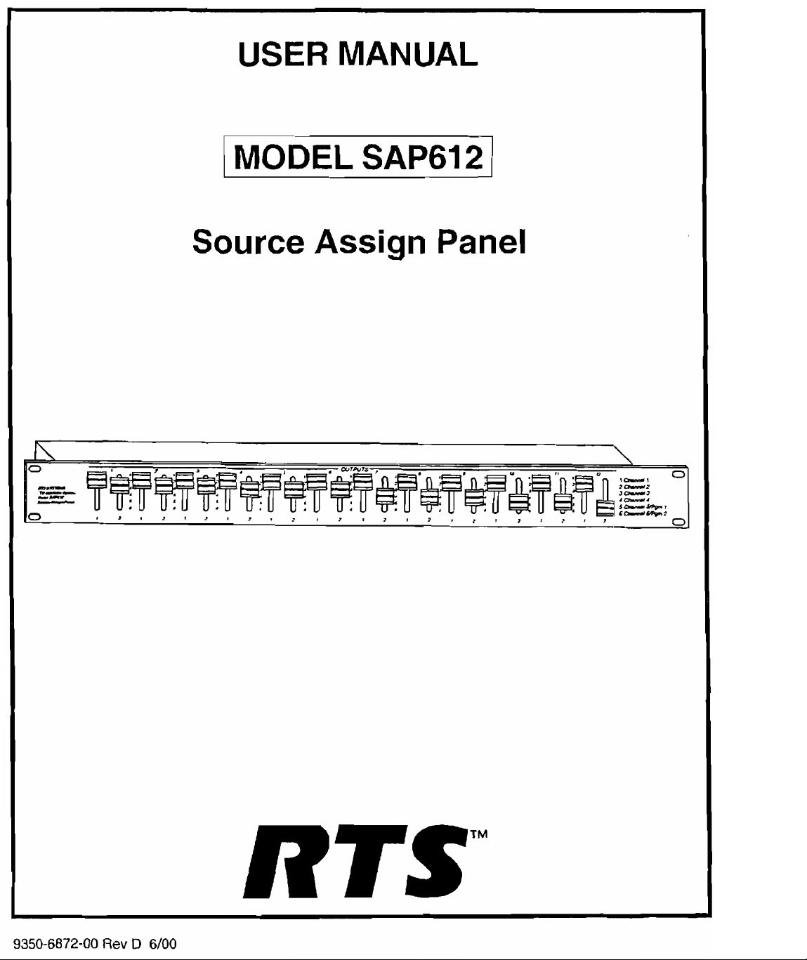
USER MANUAL
/
MODEL
SAP61
2
I
Source Assign Panel
n
0
--
we-
--
-
0
IIIIIIII~>I,ItI~III~~
\
,CU>
4-d
s-npi
<--*
0-
9350-6872-00
Rev
D
RTSTM
6/00
Page 2
PROPRIETARY NOTICE
CUSTOMER SUPPORT
'The RTS product information and desisn disclosed herein
were 01-iginatcd hy and are the property of Telex
Communications, Inc. Telcx reserves all patent,
proprietary design, nianufacturin:, reproduction, use and
sales rights thereto, and to any an~clc disclosed therein,
except to the extent rights are expressly granted to others.
COPYRIGHT NOTICE
Copyright 1901 hy Telex Communications, Inc.. All
rights reserved. Reproduction in whole or in pan without
prior written permission from Telex is prohibited.
UNPACKING AND INSPECTION
Immediately upon receipt of the equipment, inspect the
shipping container and the contents carefully for any
discreoancies or damaee. Should there be anv. notifv the
freighi company and tKe dealer at once.
WARRANTY INFORMATION
RTS products are warranted by Telex Communications.
Inc. to be free from defects
for a period of three years from the date of sale.
The sole obligation of Telcx during the warranty period is
to provide, without charge, pans and labor necessary to
remedy covered defects appearing in products returned
prepaid toTelex. This warranty does not cover any defect.
malfunction or failure caused beyond the control of Telex,
including unreasonable or negligent operation, abuse,
accident, failure to follow instructions in tlie Service
Manual or the User Manual, defective or improper
associated equipment. attempts at mtdification and repair
not authorized by Telex, and shipping damage. Products
with their serial numbers removed or effaced arc not
covered by this warranty.
To obtain warranty service, follow the procedures entitled
'.Procedi~re For Returns'' and
for Repair
This warranty is the sole and exclusive express warranty
given with respect to RTS products. It is tlie responsibility
of the user to determine kfore purchase that this product
is suitable tor the user's intended purpose.
.~NY
ISCI.UUIS(; 'I'Hf.: II\II'I.IEU \\AKK:INI'Y 01:
\IER~~IJ.~NTARIl.I~~Y ARE I.l~lI'l'~.I) IO'rIlE
.
DURATION OF
WARRANTY.
or
AND
Adjustment".
~1.1.
I~IPI.II.:D
TH~SEXPRESS
in
materials and workmanship
"Shipping
~.~nn,\vr~~s,
to Manufacturer
LI~III%D
Technical qilestions sliould he directed to.
omer Service Depanment
RETURN SHIPPING INSTRUCTIONS
PROCEDUREFORRETURNS
If a repair is necessary, contac t the dealer ,where this unit
was purchased.
If repair through the dealer is not possible, obtain a
RETURN AUTHORIZATlON from:
Customer Service Dt:panmcnt
Telex Communications, Inc.
Telephone:
Fax:
DO NOT RETURN ANY EQUIPMENT DIRECTLY
TO THE FACTORY WITHOUT FIRST
OBTAINING A RETURN AUTHOKIZ~ATION.
Be prepared to provide the company name:, address,
phone number, a person to contact regarding the repair.
the type and quantity ofequiplnent,
problem and the serial number(s).
SHIPPING
ADJUSTMENT
All shipments of RTS products should
United Parcel Service or the hest availabli: shipper,
prepaid. The equipment should be shipped in the original
packing canon; if that is not available, usc any suitable
container that is rigid and of adequate size:. If a substitute
container is used, the equipment should be wrapped in
paper and surrounded with at least four in8:hes of
excelsior or similar shock-absorbing material. All
shipments must
include the Return Authorira~ion.
Upon completio~i of any repair the equipment will be
returned via United Parcel Service or specified shipper
collect.
TO
Factory Service Department
Telex Communications. lncorpol-ated
West 1st Street
Blue Eanh, MN
(800)
(800)
MANUFACTURER FOR REPAIR OR
be
828-6107
323-0498
a
descnpt~on of the
be
made via
sent to the following address and must
56013
U.S.A.
Page 3
TABLE
OF
CONTENTS
PROPRIETARYNOTICE
COPYRIGHTNOTICE
UNPACKING AND INSPECTION 2
WARRAWINFORMATION
RETliRN SHIPPING INSTRUCTIONS 2
SECTION
1.1
DESCRIFTION
1.2SPECIFlCATIONS
SECTION
2.1 MECHANICAL INSTALLATION
2.2 ELECTRICAL INSTALLATION
1;
2:
2.2.1PO
WER
2.2.1.2 USING
2.2.1.3
DESCRIPTION AND SPECIFlCATIONS
INSTALLATION
USING OTHER POWER SOURCES
....................................................
.................................................
...............................................
.................................................
............................................
..................................
.......................................................
.....................................................
................................................
.............................................
.............................................
........................................................
TW
POWER
SUPPLIES
.......................................
.....................................
2
2
2
5
5
5
6
6
6
6
6
6
2.2.1.4 SYSTEMCAPACITY
2.2.2 INTERCOM CHANNELS
2.2.3PROGRAMSOURCES
SECTION
SECTION7:DIAGRAMS
3:
OPERATION 7
.............................................
..............................................
...............................................
6
7
7
..................................................
..................................................
8
Page 4

Front
and Rear Panel
Figure
1-1
Reference
Views
Page 5

SECTION
TIONS hlaximum Switch Carryin2 Current
1.1
1)ESCRIl'TION
GENERAL The Model SAP612 Source Assign Panel inde-
pendently assigns each oC24
TW
userstation strings) toany oneof six busses,orcommon
chaonels. All channels aqsigned to a common buss channel
can intercommunicate and exchange call signals. A typical
application is diagrammed in F~gure
power supplies (such as Models PS8 or PS15) may be
conveniently connected to the SAP612 to distribute power
the
to
a non-TW power source. Switchable 200-ohm line termina-
tions are built into the SAP612 for proper line termination
when using a non-TW power source. The SAP612 has
balanced, wnsformer isolated program inputs. Program 1
is permanently assigned to buss channel 5, and program 2
isperrnaoently assigned to buss chanrlel6.
1:
DESCRIPTION ANI) SPECIFICA-
TW
channels (I2 two-channel
1-2.
One to three
intercom stations. Or, the SAP612 may be used with
TW
two
1.2
SPECIFICATIONS
1.0 ampere per output
hlaximum Switch Brealtinr Current
0.5 ampere per outpul.
Inputs
Full duplex lines (busses):
Program Inputs: 2
Outputs (Two Channel)
User Station Strings:
Program Inputs
Impedance:
Level: 0 dBm
Powerrequirements
No external power required, Power distributed from
RTS Systems power supplies PS 15 or PS31 connecled
at rw panel of SAP612.
Size(HXWXD)
1.72 in. (44 mm) X
Allow another4.0 inches (102 mm) depth for cables
rear panel.
Weight (Mass)
4.5
lbs (2.05 kg)
Color
Grey, Fed. Std. #595A-26492
600
ohms
6
12
19
in. (483 mm) X 8 in. (201 mm).
on
-
PSB or PSI5
PSI5 (optional)
PSI5 (0-1
I
Program Sou--3
I
Program Source
Spxificarims
1
INPUTS
I->
]
2
I->
)
>
CH
1-2 2
CH
3-4 3
CH
5-6
-
are
subject
to
clmge
wilhoul
notice
,
1
4
4
WM~OOHWM~OO]
-I
SSA324
I
Typical System Diagram
Figure
1-2
1
Page 6

SECTION
'The Model SAP612 mounts in
2:
INSTAIAI.ATION
a
stmdard
19
inch rack
:~nd occupies one rack unit of height (1.72 inches).
2.2
ELECTRICAL WSTAL1,ATION
2.2.1
POWER
NOTE
%W
Most
user stations are powered from channel one,
which is called a "wet" channel because it carries the DC
current in addition to thc channcl 1 audio. Channel
2
is a
"dry" channel because it carries audio only. It is impor-
tant to
remember this, since it can have an effect on chan-
nel rissignment later (see pxag~iplrs 2.2.1.2 and
2.2.1.3
below for specifics).
2.2.1.2
Using
TW
Power Supplies
ing an additional PSR to the CH
channel one assignment to cither buss
threePS8'S would pennit buss 1.1 or
channel one assignment.) Since
3-4
TNPUT
1
or buss 3. Using
5
to be used for
TW
power supplies
would pennit
arc
equipped with termination resistors, set the terniinalion
switches on the rear panel of the SAP612 to the External
position (switch out).
2.2.1.3
Using
other Power Sources (Figure
TW
systems require 18-35 volts DC (32 volts nominal).
2-1)
The power source must provide adequate filtering so as
not to introduce noise into the system. Connect the exter-
nal power supply ground lead to pin 1 of the CH
1-2
INPUTconnector; connect the positive lead to pin 2. Set
all
termination switches to the Internal (Switched-in) posi-
tion. In this application, buss one is used lo supply powcr
only and cannot be used as an intercom buss. Channel
one of allexternally powered user stations must he as-
signed to buss ooe.
22.1.4
System Capacity
Connect
PS8 or PS 15) to the
TW
power supplies (such
CH
1-6
LNPUT
as
theRTS Models
jacks on the back of
the SAP612. One to three power supplies may be con-
nected. Using more than one power supply not only in-
crenses the system capacity, hut also offeers somewhat
in
more flexibility
PSIS supply power on cha~ii~cl one, orllin
chan~~cl assignment. (The PS8 and
2,
of
their out-
put connectors. Therefore, if only one power supply is
used, all externally powered user stations must have chan-
nel one assigned to the single powered buss. For ex-
ample, if one PS8 is connected to the CH 1-2
NUT,
all
externally powered stations musL have channel one per-
m3nently assigned to buss I on the front panel. Connect-
SET
ALL
SWITCHES
TO INTERNAL
(SWITCHED-IN)
+
Terminalran
Internal: %;l&
~~~~~
CH2 CH3
[ZOO
CH~
CHS
ohms]
-
rn
CHS PGM
POSITION
TERMINATION
SWITCHES INPUTS INPUTS
To determine power supply loading, add together all of tho
userstations that will bepowered from aparticularbuss (les:;
stations which are self-powered). Note: the SAP612 dis-
tributes DC power, but uses no power itself. Refer to your
power supply manual for power supply capacity informa-
tion.
Tp
-
Hi
Ruig
-
La
I
PGM
2
PROGRAM
INPUTS
k:H
1-2 CH
34
POWER
-
SUPPLY
18
-
35
VDC
I
Figure
2-1
J
Connecting a Non-TW Power Source
Page 7

2.2.2
INTERCOM CHANNELS
SECTION
3:
OPERATION
Connect intercom channels to the OUTPUTS 1-12 jacks
on the rear panel. Each conncctor accommodates a pair
TW
channels wired in the standard
of
figuration
PII~ 1
Pin
Plri
as
follows:
Common (low s~de of he)
2 Channel 1
3
Channel2
TLV
2-wire con-
3
NOTE
Shielded cable is recommended for user station intercon-
do
nections. Connect shields to circuit common, but
tie shields to chassis, earth or connector shell ground.
2.23
PROGRAM SOURCES
Program input 1
input 2 is assigned to buss 6. The program inputs
balanced and isolated. Connect program sources using
114-inch stereo phone plugs wired
Tip Program high
~ing Program low
Sleeve Common
(PGM
1) is assigned to buss
as
follows:
5;
not
program
are
RING
I
Jm
I
The front panel of the SAP612 contains 12 pairs of
switches: one pair Tor each user station string. The user
slation strings 1-12 are identified across the top of the
front panel. Channels
tifled along the bottom of the panel. Buss numbers 1-6
are identified to the right of each pair of switches. Assign
an
intercom channel to a buss by setting the appropriate
switch to the desired buss number.
to
a
particular buss can intercommunicate and exchange
call signals.
1
and 2 for each string arc idcn-
All
channels assigned
IMPORTANT
I
bch
TW
user station that receivespower via the
SAP612 must have channel 1 assigned to a
powered buss.
I
Page 8

Document
Nlm!m
SECTION
7:
DIAGRAMS 1 DRAWINGS
Assembly Drawing. Connector Board, Model
Schematic Diagram, Front Panel
Schen~atic Diagram, Source
Switch
Assign
Board, Model
Panel. Model
SAP612
SAP612
SAP612
Page 9

Page 10

 Loading...