

Page 1

RVON Resource Guide
RVON-8
RVON-1
RVON-I/O
Page 2

Page 3

CHAPTER 1
Basic Network Configuration
Basic Network Configuration
This section covers basic network configuration set-up and testing. Also covered are basic concepts and
operations, including the difference between LAN and WAN networks and how IP Addressing is used.
In a networked environment, such as a company, typically there are many computers connected together using a
router or a switch. In larger companies, there may be several different routers distributed in buildings and plant
locations. A router allows any LAN-side computer to communicate with other computers and devices outside the
LAN (local area network). Routers send data packets from one place to another place on a network. routers use
network addresses to route packets to the correct destination. For example, in a TCP/IP network, the IP (internet
protocol) address of the network interface is used to direct router destinations.
Because routers help computers inside the LAN “talk” with computers outside of the LAN, the security of a
company’s LAN may be compromised by gaps of open ports in the router. Security measures may have been
instituted to compensate for these vulnerabilities. Consult you network administrator to learn about the security
measures taken to protect your network. VPN, or virtual private network, is one such security measure to protect
the intelligence of the LAN. A computer outside the LAN must have an address or key known by the VPN to
allow access to the LAN. Many companies use a VPN to connect two different LANs, thus allowing the transfer
of data between two networks.
LAN (local area network) vs. WAN (wide area network)
LOCAL AREA NETWORK
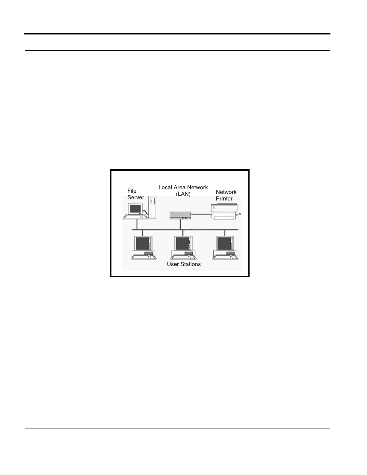
Simply put, a LAN is a computer network that connects a relatively small area (a single building or group of
buildings). Most LANs connect workstations and computers to each other. Each computer (also known as a
3
Page 4
Basic Network Configuration
“node”), has its own processing unit and executes its own programs; however, it can also access data and devices
anywhere on the LAN. This means many users can access and share the same information and devices. A good
example of a LAN device is a network printer. Most companies cannot afford the budgetary or hardware expense
of providing printers for each of its users; therefore, one printer (or device) is placed on the LAN where every
user can access the same printer.
The LAN uses IP Addresses to route data to different destinations on the network. An IP Address is a 32-bit
numeric address consisting of four numbers separated by periods (for example, 1.160.10.240).
NOTE: For more information on IP Addresses, see you local network administrator.
Figure 1. Local Area Network Diagram
4
Page 5
Basic Network Configuration
WIDE AREA NETWORK
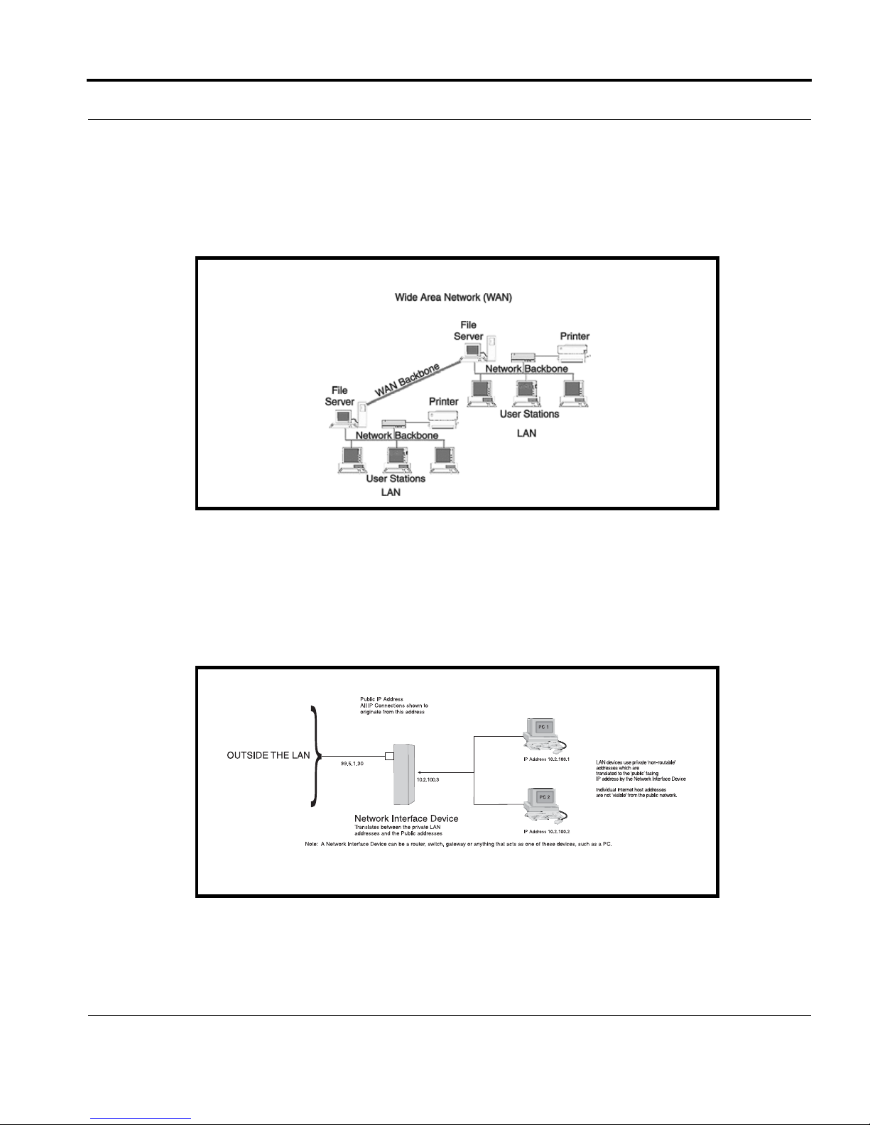
A wide area network (WAN) connects two or more LANs and can span a relatively large geographical area. For
example, Telex Headquarters in Burnsville, MN is connected to several branch offices in Nebraska and
Arkansas over a WAN. The largest WAN in existence is the Internet.
Figure 2. Wide Area Network Diagram
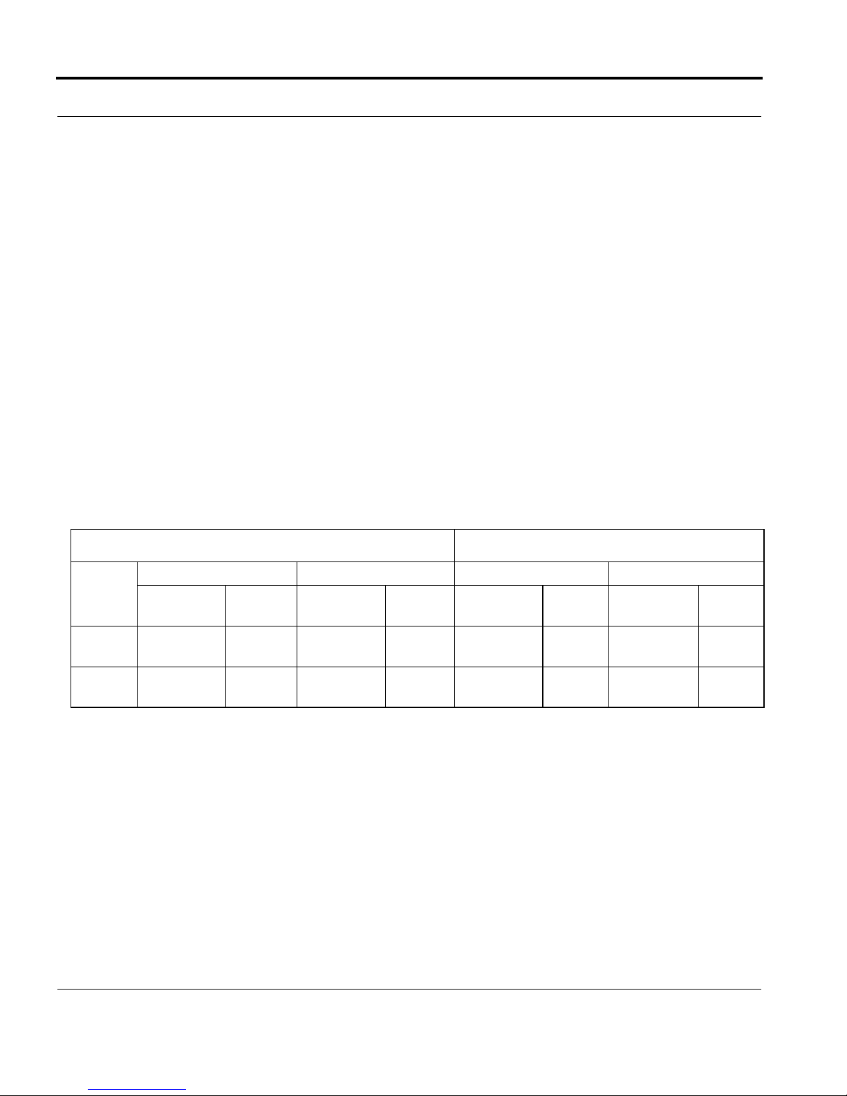
ACCESSING THE WIDE AREA NETWORK (WAN)
Figure 3 shows LAN IP Addresses using a common IP Address, 10.2.100.X (192.168.X.X is another common
address). Most devices are shipped with these addresses as its default. It is recommended to use these addresses
for LANs.
Figure 3. Network Address Translation
5
Page 6
Basic Network Configuration
NETWORK ADDRESS TRANSLATION (NAT)
Using the initial IP Address, then converting it to a valid WAN IP Address is how the network address translation
works, in theory. Once the IP address is changed, it is up to the network interface device (such as a router,
gateway, switch, etc.) to keep track of which computers are talking on which ports. For example, if two local
devices (PC1 and PC2 in Figure 3) both wanted to talk via port 1031, then the network interface device would
have to change one of the port requests to the next available port, 1032.
PORTS
In general, a network port is an endpoint to a logical connection. The port number identifies what type of port it
is. For example, port 80 is used for HTTP traffic. When you type an address into the address bar of a web
browser, your computer goes to find an IP Address for the url you are requesting (http://www.telex.com). To
obtain this address, the computer contacts a DNS server (Domain Name Server). Once the IP Address is found, it
tries to connect to the http port of the network device (port 80). See Table 1 for a list of the more well-known port
numbers.
Each network device can be set-up to respond or not respond to the various ports. The function of responding or
“hosting a service” is called “serving”.
TABLE 1. Packet Translation
Packet before Translation Packet after Translation
Source Destination Source Destination
To
Internet
From
Internet
IP Address
10.2.100.2 1031 192.156.136.22 80 99.5.1.30 1031 192.156.136.22 80
192.156.136.22 80 99.5.1.30 1031 192.156.136.22 80 10.2.100.2 1031
Port
Number
IP Address
Port
Number
IP Address
Port
Number
IP Address
Port
Number
If a second workstation on the LAN wants to communicate to the same server, and happens to use the same
source port number, then the LAN Modem will translate the source port number as well as the source IP address.
In Table, 2, a second LAN computer wants to access a web page. The NAT device now uses port 1032 for this
connection where it used port 1031 in Table 1.
6
Page 7
Basic Network Configuration
TABLE 2. Packet Translation
Packet before Translation Packet After Translation
Source Destination Source Destination
To
Internet
From
Internet
IP Address
10.2.100.1 1031 192.156.136.22 80 99.5.1.30 1032 192.156.136.22 80
192.156.136.22 80 99.5.1.30 1032 192.156.136.22 80 10.2.100.1 1031
Port
Number
IP Address
Port
Number
IP Address
Port
Number
IP Address
Port
Number
Amazingly, all the address translation that occurs takes place automatically in order to make web browsing and
other functions easier. This is also a way for large web hosting services to speed up the network by having
different devices perform different functions.
7
Page 8

Basic Network Configuration
TABL E 3. Well-Known TCP Port Numbers
TABLE 3. Well-Known TCP Port Numbers
Port
Number Description
1 TCP Port Service Multiplexer (TCPMUX)
5 Remote Job Entry (RJE)
7ECHO
18 Message Send Protocol (MSP)
20 FTP-Data
21 FTP- Control
23 Telnet
25 Simple Mail Transfer Protocol (SMTP)
29 MSG ICP
37 Time
42 Host Name Server (Nameserv)
43 Whols
49 Login Host Protocol (Login)
53 Domain Name Server (DNS)
69 Trivial File Transfer Protocol (TFTP)
70 Gopher Service
79 Finger
80 HTTP
103 X.400 Standard
108 SNA Gateway Access Server
109 POP2
110 POP3
Port
Number Description
115 Simple File Transfer Protocol
118 SQL Services
119 Newsgroup (NNTP)
137 NetBIOS Name Service
139 NetBIOS Datagram Service
143 Interim Mail Access Protocol (IMAP)
150 NetBIOS Session Service
156 SQL Server
161 SNMP
179 Border Gateway Protocol (BGP)
190 Gateway Access Control Protocol (GACP)
194 Internet Relay Chat (IRC)
197 Directory Location Services (DLS)
389 Lightweight Directory Access Protocol (LDAP)
396 Novell Netware over IP
443 HTTPS
444 Simple Network Paging Protocol (SNPP)
445 Microsoft-DS
458 Apple Quick Time
546 DHCP Client
547 DHCP Server
563 SNEWS
569 MSN
1080 Socks
8
Page 9
Basic Network Configuration
IP ADDRESSES
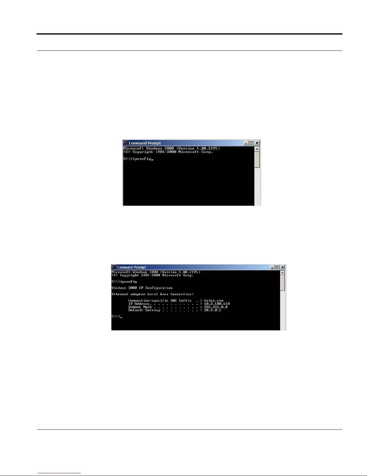
If you do not know your IP Address, you can open a DOS screen in a Windows®- based environment and bring
up the ipconfig screen.
To find your IP Address using ipconfig, do the following:
1. From the Start Menu, open a Command Prompt screen.
2. At the prompt, type ipconfig, then press Enter.
The IP configurations appear for your machine, such as the DNS suffix, IP Address, Subnet Mask, and
Default Gateway.
3. At the prompt, type Exit to close the screen.
NOTE: If you want more detailed parameters for your machine, type ipconfig/All. This screen shows the
computers network configuration settings.
9
Page 10
Basic Network Configuration
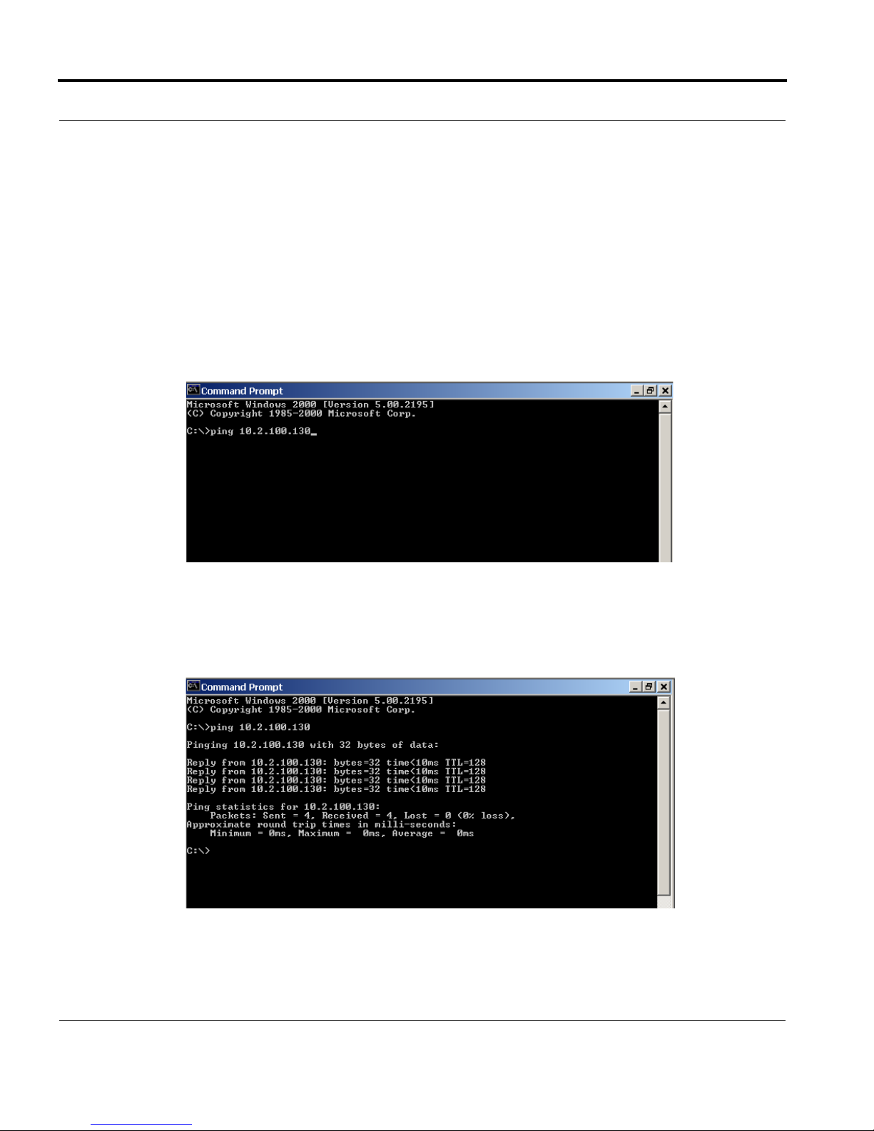
Ping a Computer
Pinging a computer on the network makes sure it is able to be “seen” and receive messages on the network.
NOTE: You can also ping your RVON-8 card to verify that it is responding over the network by putting the cards
IP Address in place of the computer IP Address.
To Ping a computer on the network, do the following:
1. From the Start menu, select Run... .
2. At the Run command, type CMD to open a Command Prompt screen.
3. At the prompt, type the IP Address of the computer you wish to ping (for example, 10.2.100.130).
4. Press Enter.
10
Page 11
Basic Network Configuration
NOTE: If the computer you are pinging is not responding to the ping, you will receive a time-out message in the
command prompt screen.
POSSIBLE PITFALL WITH ROUTERS, GATEWAYS, AND SWITCHES
Anytime computers communicate through routers, gateways, and switches, they may be allowed or denied the
connection. Network interface devices can be configured to block specific outgoing requests, as well as
incoming requests, based on the IP Address and/or port. This is one of the security mechanisms of a router. This
also happens when broadcast messages are sent and received.
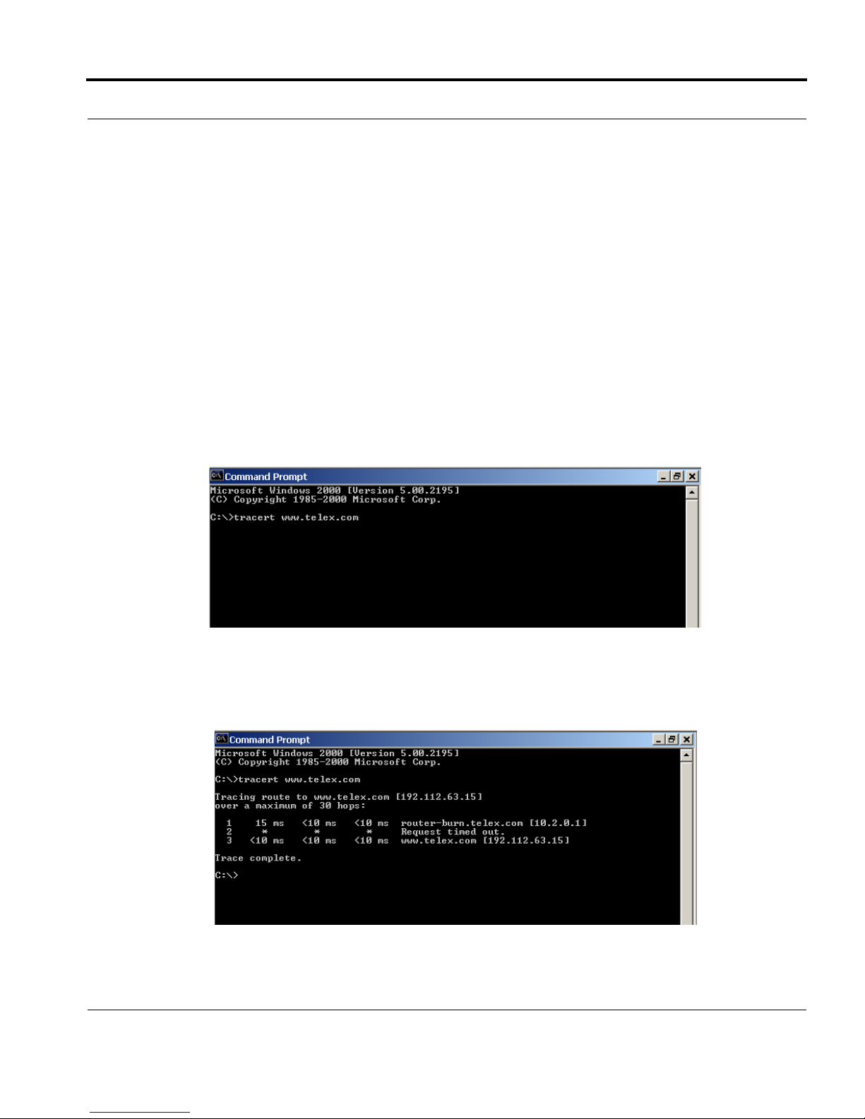
To view the path an IP Address takes to retrieve information, you can execute a tracert from the Command
Prompt Screen.
1. From the Start Menu, open a Command Prompt screen.
2. At the prompt, type tracert and type the url or IP Address you want to trace.
3. Press Enter.
The details of the tracer route are displayed.
11
Page 12

Basic Network Configuration
NOTE: You will the message “request timed out” if the IP Address/ port IN or OUT is denied to the incoming or
outgoing message.
4. When you are finished, type exit to close the Command Prompt screen.
RVON Configuration
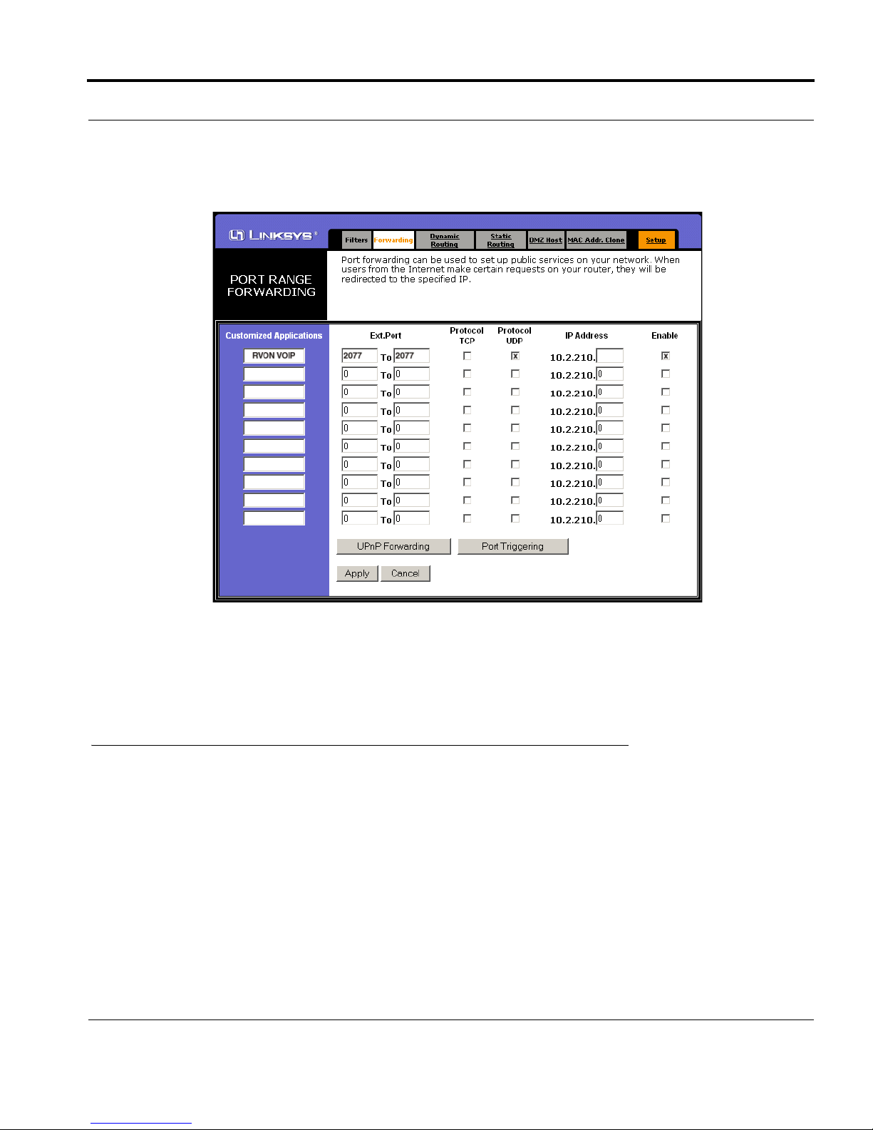
RVON cards use ports for communication of audio and control packets. Because routers can be configured to
block certain incoming and outgoing requests, you will need to open the following ports in your network to allow
WAN connections to and from a Network Interface Device. See Table X for the ports that need to be opened for
the RVON cards to operate properly.
TABLE 4. Ports necessary for RVON card functionality.
Port Port Description
2076 UDP Call Control Signalling
2077 UDP Audio Packets
2079 UDP Telex Proprietary Signalling
2080 TCP Telex Keypanel Protocol
2081 UDP Pass Through Serial
2082 TCP Firmware Download
2100 Remote Administration
2102 Authentication Server
12
Page 13
Network Terminology
Figure X is an example of a router configuration screen. Not all routers are configured the same way and may
not look exactly like this screen.
NOTE: Linksys™ supports up to 253 nodes on a router. This is why it is called a Router/Switch because there
are WAN functions like a router as well as having a 4-port LAN switch. It also does not support simultaneous
forward and DHCP.
Network Terminology
Bridges
A bridge is a device that connects two LANs, or two segments of the same LAN that use the
same protocol. Sometimes called “transparent bridges, they work at the OSI model Layer 2.
Simply put, they are not concerned with protocols. Their main job is to pass data to a
destination address that is predetermined in the data packet.
With a bridge, all of your computers are on the same network subnet (see Subnet). This means
your computers can communicate with each other and have their own Internet connection. If
you assign your own IP Addresses be sure to use the same first 3 “octets” of the IP Address
(for example, 192.168.0.X).
13
Page 14

Basic Network Configuration
Domain Name Server (DNS)
A DNS Server is an Internet service that translates domain names (for example, in the URL
http://www.telex.com, the domain name is the telex.com) into IP Addresses. The Internet is
based on IP Addresses which are numeric and since domain names are alphabetic, they are
easier to remember. Every time a domain name is used it must go through the DNS server to be
translated into an IP Address.
Gateway
A gateway is a node on a network that serves as an entrance to another network. The gateway
routes traffic from a computer to an outside network that is serving the web pages. For
example, the gateway for a home computer is the ISP provider that connects the user to the
Internet.
In a corporate environment, the gateway often acts as a proxy server and a firewall. Gateways
are similar to routers and switches in that they forward data to the destination and provide the
path for which the data will travel to the destination.
Hub
A hub is a common connection point for devices in a network. A hub has multiple ports. When a
data packet arrives at a hub, it is copied and distributed to all of its ports so that all nodes on the
LAN can see the packets.
There are three types of hubs:
passive hub
- this hub serves as a conduit for the data, enabling it to go from one device to another.
intelligent hub (also known as manageable hubs) - this hub includes addition features that enable
administrators to monitor traffic through the hub.
switching hub - this hub reads the destination address of each packet and then forwards the data
pack to the appropriate port.
IP Address (Internet Protocol Address)
An IP Address is an identifier or numerical name for a computer or device on a network. Data
between computers are routed over the network using these addresses to identify the computer
the message is being sent to and the computer the message is being sent from.
The format of an IP Address is a 32-bit numeric address written as four numbers separated by
periods. For example, an IP Address looks like 10.100.1.1.
IMPORTANT: When working within an isolated network (meaning there is no Internet
access), IP Addresses can be assigned at random just as long as they are unique to each
computer and device. When the isolated network is connected to the Internet, registered
Internet Addresses must be obtained. This is to prevent duplication of addresses.
14
Page 15

Network Terminology
The four numbers in and IP Address are used in different was to identify a particular network
and host on that network. There are three classes of Internet Addresses.
CLASS A - supports 16 million hosts on each of 127 networks.
CLASS B - supports 65,000 hosts on each of 16,000 networks.
CLASS C - supports 254 hosts on each of 2 million networks.
LAN
A LAN is a computer network that connects a relatively small area (a single building or group
of buildings). Most LANs connect work stations and computers to each other. Each computer
(also known as a “node”), has its own processing unit and executes its own processing unit and
executes its own programs; however it can also access data and devices anywhere on the LAN.
This means that many users can access and share the same information and devices. A good
example of a LAN device is a network printer. Most companies cannot afford the budgetary or
hardware expense of providing printers for each of its users; therefore, one printer (i.e., device)
is placed on the LAN where every user can access the same printer.
The LAN uses IP Addresses to route data to different destinations on the network. An IP
Address is a 32-bit numeric address written as four numbers separated by periods (for example
1.160.10.240).
Port
A port, when referring to TCP and UDP networks, is an endpoint in a logical connection. The
port number identifies the type of port it is. For example, port 80 is used for HTTP traffic.
15
Page 16

Basic Network Configuration
Routers
A router is a device that forwards data packets over networks. Most commonly, a router is
connected to at least two networks (normally LANs or WANs). Routers are located at
gateways, the place where two networks are connected. Routers do little data filtering, they
mainly deliver the data.
Subnet
A subnet is a portion of a network that shares a common address component. On a TCP/IP
network, a subnet is described as all computers or devices whose IP Address have the same
prefix.
Subnetting a network is useful because it provides security for the network as well as increases
performance of the network. IP networks are divided using subnet masks.
Switches
A switch is a device that filters and forwards data packets between networks. Switches operate
at the data layer, and sometimes at the network layer.
WA N
A wide area network connects two or more LANs and can span a relatively large
geographical area. For example, Telex Headquarters in Burnsville, MN is connected to several
of its branch offices in Nebraska and Arkansas over the wide area network. The largest WAN is
the Internet.
16
Page 17

CHAPTER 2
Serial Port Programming
RVON Serial and Telnet Commands
RVON card programming can be done via direct serial or telnet connection. There are several physical
connections to an RVON board:
• Direct serial through custom debug cable (J20 6-pin bottom front)
The customer debug cable always functions as the general-purpose debug tool.
• Backcard DB-9 J2
The backcard DB-(must be disabled/enabled via a DIP Switch because it can also be used for serial port passthrough. The backcard DB-9 can be used for a debug terminal when DIP switch 6 is switched to the ON
position.
• Backcard RJ-45 J1 (Telnet Only)
Setup
Serial Port 38.400 baud, No-flow control
Telnet IP Address, port 23
17
Page 18

Serial Port Programming
TABLE 1. RVON-I/O supplemental Coding Table
Codec
Coding Codec
Rate Size VAD
1 711u 64k 10 Y
2 711u 64k 20 Y
3 711u 64k 30 Y
4 711u 64k 10 N
5 711u 64k 20 N
6 711u 64k 30 N
7 711A 64k 10 Y
8 711A 64k 20 Y
9 711A 64k 30 Y
10 711A 64k 10 N
11 711A 64k 20 N
12 711A 64k 30 N
13 729AB 8k 10 Y
14 729AB 8k 20 Y
15 729AB 8k 40 Y
16 729AB 8k 60 Y
17 729AB 8k 10 N
18 729AB 8k 20 N
19 729AB 8k 40 N
20 729AB 8k 60 N
21 723 5.3k 30 Y
22 723 5.3k 60 Y
23 723 5.3k 30 N
24 723 5.3k 60 N
25 723 6.3k 30 Y
26 723 6.3k 60 Y
27 723 6.3k 30 N
28 723 6.3k 60 N
18
Page 19

Table 1. Codec Specifications.
Codec
Coding Profile
0,3,6,9 G.711 64k 10 100.00 80 60 140 14000 112 224
1,4,7,10 G.711 64k 20 50.00 160 60 220 11000 88 176
2,5,8,11 G.711 64k 30 33.33 240 60 300 10000 80 160
12,16 G.729 8k 10 100.00 10 60 70 7000 56 112
13,17 G.729 8k 20 50.00 20 60 80 4000 32 64
14,18 G.729 8k 40 25.00 40 60 100 2500 20 40
15,19 G.729 8k 60 16.67 60 60 120 2000 16 32
20,22 G.723 5.3k 30 33.33 24 60 84 2800 22.4 44.8
24,26 G.723 6.3k 30 33.33 24 60 84 2800 22.4 44.8
21,23 G.723 5.3k 60 16.67 48 60 108 1800 14.4 28.8
25,27 G.723 6.3k 60 16.67 48 60 108 1800 14.4 28.8
Codec Rate
Audio (ms) / Packet
Packets/Second
Encoded Audio (bytes)
IP Overhead (bytes)
Total Packet Size (bytes)
Bandwidth (Bytes/sec)
Bandwidth (kbps/side)
Bandwidth (kbps/channel)
NOTE: A channel consists of a transmitting and a receiving side, so the bandwidth is double for a bi-directional audio stream.
NOTE: Bandwidth values are approximate maximums, actual bandwidth could be considerably lower with VAD enabled.
Codec: Determines how the audio is compressed/decompressed and the name given to the defined
algorithm.
Codec Rate: Actual bits per second of the audio in compressed form. This is sent over the network
through various data packets. Network efficiency can be calculated with an IP header for
each packet of X ms of audio.
Size: Amount of audio in each IP Packet, milliseconds (ms)
VA D : Voice Activity Detection, when enabled and only when audio is above a certain threshold,
will send packets. Otherwise, a silence packet is sent once, and not again until audio is
above the threshold. Enabling this will result in a more efficient network, but care must be
taken to because of the mother’s day phenomenon. If there is ever a need to have all audio
paths open and active, a network designer must account for this scenario.
19
Page 20

Serial Port Programming
20
Page 21

*****************************************************
RVON−8 Revision 1.00.00
(C) Copyright 2003 Telex, Inc. All Rights Reserved.
Flash File System initialized.
DIP Switch settings:........X
Configuration via AZedit disabled (via DIP Switch 1 ON)
Back Card UART enabled for pass−through serial (via DIP Switch 6 OFF)
Boot Downloader disabled (via DIP Switch 7 OFF)
Autoload enabled (via DIP Switch 8 OFF)
Monitor Revision 1.00.00
Monitor Compilation time Sept 4 2003, 15.52.31
Board type / revision 0 (RVON−8) / 1
RTL ID / revision 9 (RVON−8) / 0.16
Processor ID / Revision 0x80 (4Kc) / 0x50
Avalanche Device Type Avalanche−I, Revision 1.3
Memroy Controller Revision 1.204
Endianness Big
External Memory rate Full
CPU Frequency 125 MHz
Flash memory size 8 MBytes
RAM size 64 MBytes
First free RAM address 0x9401fla8
PLL Mode Operating 2.50X
Press any key to abort OS load, or wait 5 seconds for OS to boot....
**Defragmenting File System flash area(s)**
Reading flash file system... No deleted flash file entries found.
Loading file/ bin/telex1 from EFS
PC: 94020000
FTP done!, PC: 94020000
Target Name: vxTarget
Attached TCP/IP interface to emac unit 0
Attaching network interface 1o0,,, done
NFS client support not included.
Adding 5270 symbols for standalone.
appCreate: autoBootLevel=2
MXP environment is created.
Creating RVON−8 application...
−> Bringing DSP subsystem out of reset...
DSP Daughtercard type is set to NONE − No DSP Daughtercard Found
0000002223 − ROOT: FPGA Version = ff24
0x97e796f0 (tNetTask): Link is up on EMAC A: 100 MBps and HALF duplex.
21
Page 22

About to create Idle Task
About to create Measurement Task
Idle Measurement Tasks created
0000002536 − SERV: initializing connection server
0000002536 − DNLD: initializing download server
0000002535 − NMM: ATPM Update Database Granted
0000002735 − NMM: ATPM Configured for RVON operation
0000002735 − NMM: ATPM Update database done
0000002735 − NMM: 0, states: oper=NORMAL, admin=NORMAL, call=IDLE
0000002741 − NMM: 1, states: oper=NORMAL, admin=NORMAL, call=IDLE
0000002742 − NMM: 2, states: oper=NORMAL, admin=NORMAL, call=IDLE
0000002743 − NMM: 3, states: oper=NORMAL, admin=NORMAL, call=IDLE
0000002744 − NMM: 4, states: oper=NORMAL, admin=NORMAL, call=IDLE
0000002744 − NMM: 5, states: oper=NORMAL, admin=NORMAL, call=IDLE
0000002745 − NMM: 6, states: oper=NORMAL, admin=NORMAL, call=IDLE
0000002746 − NMM: 7, states: oper=NORMAL, admin=NORMAL, call=IDLE
0000002746 − RVON: port 0, now idle
0000002746 − RVON: port 1, now idle
0000002746 − RVON: port 2, now idle
0000002746 − RVON: port 3, now idle
0000002746 − RVON: port 4, now idle
0000002746 − RVON: port 5, now idle
0000002746 − RVON: port 6, now idle
0000002746 − RVON: port 7, now idle
0000003037 − CBTX: MC/DBX is talking
0000003041 − FNRX: control bus FIFO now enabled
0000003093 − FNRX: new card configuration received
Following the power-ON messages, press Return.
The -> appears. This is the operating system prompt.
There are many different serial port commands support from here, but is NOT recommended that any be used
EXCEPT:
dbgcmd
Type “dbgcmd”, then press Return.
This places the serial port into the MXP> (MXP command mode)
The MXP Command Mode is the only mode that will be used. Table 1 is a list of commands support from the MXP
Shell Prompt.
22
Page 23

RVON-8 Command Table
RVON-8 Command Table
TABLE 5. RVON-8 Command Table
Command Variable 1 Variable 2 Description
set rvon Help screen which lists all “set rvon” commands.
set rvon ip_addr X.X.X.X Set the IP Address for the RVON-8 Card.
set rvon netmask X.X.X.X Set network mask for the RVON-8 Card.
set rvon gateway X.X.X.X Set the gateway IP Address for the RVON-8 card.
set rvon user abcdefg
set rvon password abcdefg
set rvon vad_threshold [adaptive ⎢#]
Set the VAD threshold (silence detection) Adaptive
refers to auto-select. The # can be -20 to +10dBm.
Set the RVON-8 user name for telnet access.
Default “telex”
Set the RVON-8 password for telnet access (8-40
characters).
Default “password”
set channel
[chan]
set channel
[chan]
set channel
[chan]
set channel
[chan]
set channel
[chan]
set channel
[chan]
set emac auto*
set emac 10 half
set emac 10 full
set emac 100 half
Help screen which lists all “set tcid” commands
(TCID 0-7).
dest_ip X.X.X.X
dest_type X dest_type X = 0 (rvon-8), 1 (rvon-1), 2 (rvon-I/O).
chan_codec X
onhook Force the channel to disconnect the port.
offhook Force the channel to connect the port.
Set the destination IP Address for this particular
RVON_Channel (same as tcid).
Set the profile to use which includes the compression
codec see below (0-27).
Enables auto-negotiation of the Ethernet interface
configuration.
Configures the Ethernet interface for 10Mbps half
duplex.
Configures the Ethernet interface for 10Mbps full
duplex.
Confgures the Ethernet interface for 100 Mbps half
duplex.
23
Page 24

TABLE 5. RVON-8 Command Table
Command Variable 1 Variable 2 Description
set emac 100 full
Configures the Ethernet interface for 100 Mbps full
duplex.
set serial ip_addr X.X.X.X
Set the destination IP Address for this serial pass-
through port.
set serial baud X Set the baud rate to use: 50 through 115000.
activate
Must do an activate command to cause changes to
take effect.
show rvon Display current settings
show channel
[chan]
Display current settings
show emac Display current settings
24
Page 25

RVON-1 Command Table
RVON-1 Command Table
TABLE 6. RVON-1 Command Table
Command Variable 1 Variable 2 Description
set rvon Help screen which lists all “set rvon” commands.
set rvon ip_addr X.X.X.X Set the IP Address for the RVON-1 Card.
set rvon netmask X.X.X.X Set network mask for the RVON-1 Card.
set rvon gateway X.X.X.X Set the gateway IP Address for the RVON-1 card.
set rvon user abcdefg
set rvon password abcdefg
set rvon vad_threshold [adaptive ⎢#]
Set the RVON-1 user name for telnet access.
Default “telex”
Set the RVON-1 password for telnet access (8-40
characters).
Default “password”
Set the VAD threshold (silence detection) Adaptive
refers to auto-select. The # can be -20 to +10dBm.
set channel [chan]
set channel [chan] dest_ip X.X.X.X
set channel [chan] dest_type X dest_type X = 0 (rvon-8), 1 (rvon-1), 2 (rvon-I/O).
set channel [chan] dest_chan X
set channel [chan] chan_codec X
set channel [chan] onhook Force the channel to disconnect the port.
set channel [chan] offhook Force the channel to connect the port.
activate
show rvon Display current settings.
show channel
[chan]
Help screen which lists all “set chan” commands
(CHAN 0-7).
Set the destination IP Address for this particular
RVON channel.
Set the destination channel - the port at the far end of
the connection (0-7).
Set the profile to use, which includes the
compression codec see below (0-27).
Must do an activate command to cause changes to
take effect.
Display current settings
25
Page 26

26
Page 27

RVON-I/O Command Table
RVON-I/O Command Table
TABLE 7. RVON-I/O Command Table
Command Parameter 1 Parameter 2 Description
show rvon
show channel
show serial Shows serial port setting.
show gpio Shows gpio settings.
show panel
show emac Shows Ethernet settings.
set rvon Help screen which lists all “set rvon” commands.
set rvon ip_addr X.X.X.X Set the IP Address for the RVON-I/O.
set rvon netmask X.X.X.X Set the Network Mask for the RVON-I/O.
set rvon gateway X.X.X.X Set the Gateway IP Address for the RVON-I/O.
set rvon user username
set rvon password password
set rvon vad_threshold adaptive (#)
Shows RVON-I/O IP Address and other general
information.
Shows destination address and connection
information.
Shwos the channel control settings (poll id and
baud rate).
Set the RVON-I/O user name for Telnet access.
Default = telex
Set the RVON-I/O password for Telnet access (8-
40 characters).
Default = password
Set the VAD threshold (silence detection).
Adaptvie refers to autoselect. The # can be -20 to
+10 dBm.
set channel
[chan]
set channel
[chan]
set channel
[chan]
set channel
[chan]
set channel
[chan]
dest_ip X.X.X.X
dest_type X X = 0 (rvon-8), 1 (rvon-1, 2 (rvon-I/O
dest_chan X
chan_codec X
Help screen, which lists all “set chan” commands
(0-7). This refers to VOIP channel setting.
Set the destination IP Address for this particular
RVON channel.
Set the destination channel - the port on the far
end (0-7).
Set the profile to use which includes the
compression codec (see page X) (0-27).
27
Page 28

TABLE 7. RVON-I/O Command Table
Command Parameter 1 Parameter 2 Description
set channel
[chan]
set channel
[chan]
set channel
[chan]
set channel
[chan]
input_gain X
output_gain X
onhook force the channel to disconnect.
offhook force the channel to connect.
Set the input gain for the specified channel -14 to
Set the output gain for the specified channel -14
+14dB
to +14 dB.
set serial
Help screen, which lists all “set serial”
commands.
Set the serial mode.
set serial mode X
0 = Pass Through mode
set serial ip_addr X.X.X.X
Set the destination IP Address for this serial pass-
through port.
set serial ip_addr_2 X.X.X.X Not Available
Set the baud rate to use:
set serial baud X
50 through 115000.
set gpio Help screen, which lists all “set gpio” commands.
Set the gpio mode.
0 = Pass Through
set gpio mode X
1 = 1 Keypanel
2 = All Keypanels
set gpio ip_addr X.X.X.X
set gpio panel X
Set the destination IP Address for pass-through
mode.
Set the IO port the gpio are associated with on the
RVON-I/O.
set panel
28
Help screen, which lists all “set panel”
commands.
Page 29

RVON-I/O Command Table
TABLE 7. RVON-I/O Command Table
Command Parameter 1 Parameter 2 Description
Make sure the panel poll_id corresponds to the
set panel [pnl] poll_id X
set panel [pnl] baud X
source of the audio it is connected to.
0-10
0= do not respond to polls
Set the baud rate for the panel.
9600 or 76800
29
Page 30

30
Page 31

Default RVON-8 Setup
Default RVON-8 Setup
Every attempt is made to ensure the board is shipped from the factory containing the following:
All are “set rvon” commands
TABLE 1. Default Set RVON-8 Commands
Variable Environment Name Default Value Description
ip_addr EMACA_IPADDR 192.168.1.1 IP Address for the RVON-8 card.
netmask EMACA_NETMASK 255.255.255.0 Network mask for the RVON-8 card.
gateway EMACA_GW none Gateway IP Address for the RVON-8 card.
serial_ip RVON_SERIAL_IP none Pass-thru serial port IP Address for the RVON-8
serial_baud RVON_SERIAL_BAUD 9600
user RVON_USER telex RVON-8 user name for Telnet access
password RVON_PASSWORD password
vad_threshold RVON_THRESHOLD_VAD adaptive VAD Threshold
Set the pass-thru serial port baud rate for the
RVON-8 card
RVON-8 password for Telnet access (8-40
characters)
There are more parameters that the software will auto-configure if they have not been previously setup. The user
can also set these parameters, in which case the software would not modify, but take them as they are.
All are “set chan #” commands because they are for each audio channel.
TABLE 2. Set Chan # Setup Commands
Variable Environment Name Value Description
dest_ip RVON_DEST_IP_# X.X.X.X
dest_type RVON_DEST_TYPE_# X
dest_chan RVON_DEST_CHAN_# X Destination Channel - What port of far-end (0-7).
chan_codec RVON_CHAN_CODEC_# X Profile to use (see coding table)
Destination IP Address for this particular
RVON_CH
Destination Type - Y = 0 (rvon-8), 1 (rvon-1),
2 (rvon-I/O).
Typing “printenv”, then pressing Return from RVON-8 boot code or “sys_printenv” from the “MXP” debug
system prompt may show these commands. The Environment name is listed because this is the label used by the
software.
IMPORTANT: If the user is attempting to do a “setenv” to change a parameter from the RVON-8 boot code, the
Environment Name must be used, NOT the “set rvon” Variable name.
31
Page 32

Default RVON-1 Setup Commands
Every attempt is made to ensure the board is shipped from the factory containing the following:
All are “set rvon” commands
TABLE 1. Default RVON-1 Setup Commands
Command Environment Name Default Value Description
ip_addr EMACA_IPADDR 10.2.210.170 IP Address for the RVON-1 card.
netmask EMACA_NETMASK 255.255.255.0 Network mask for the RVON-1 card.
gateway EMACA_GW none Gateway IP Address for the RVON-1 card.
user RVON_USER telex RVON-1 user name for Telnet access.
password RVON_PASSWORD password
vad_threshold RVON_THRESHOLD adaptive VAD Threshold
There are more parameters the software will auto-configure if they have not been previously setup.
All are “set channel #” commands because they are for each audio channel.
RVON-1 password for Telnet access (8-40
characters).
TABLE 2. Set Channel # Setup Commands
Environmental Variable
Command
dest_ip RVON_DEST_IP_# (0,1) X.X.X.X
dest_type
dest_chan
chan_codec
RVON_DEST_TYPE_#
(0,1)
RVON_DEST_CHAN_#
(0,1)
RVON_CHAN_CODEC_#
(0,1)
Name Value Description
Destination IP Address for this particular
channel.
X
X Destination Channel - what port of far-end (0-7).
X Profile to use (see coding table).
Destination Type: X = 0 (rvon-8), 1 (rvon-1),
2 (rvon-I/O).
Typing “sys_printenv” from the “MXP” Debug system prompt these settings.
32
Page 33

Default RVON-I/O Setup
Default RVON-I/O Setup
Every attempt is made to ensure the board is shipped from the factory containing the following settings.
All are “set rvon” commands
COMMAND DEFAULT VALUE DESCRIPTION
ip_addr 192.168.0.1 IP address for the RVON-I/O
netmask 255.255.0.0 Network mask for the RVON-I/O
gateway none Gateway IP address for the RVON-I/O
user telex RVON-I/O username for Telnet access.
password password RVON-I/O password for Telnet access (8-40 characters).
vad_threshold adaptive VAD Threshold
Tab le 1 .
There are more parameters the software will auto-configure if they have not been previously setup.
All are “set channel #” commands because they are for each audio channel.
Set rvon default values. For more information shee table on page X.
COMMAND DEFAULT VALUE DESCRIPTION
dest_ip X.X.X.X Destination IP Address for this particular channel.
dest_type X Destination type X = 0 (rvon-8), 1 (rvon-1), 2 (rvon-I/O)
dest_chan X Destination channel - the port on the far end (0-7)
chan_codec X Profile to use (previous coding table).
Tab le 2 .
Set Channel # commands
33
Page 34

34
Page 35

CHAPTER 8
Product Specific Descriptions
35
Page 36

Product Specific Descriptions
RVON-1 Jumpers and Connections
A selectable RS232/485 serial port is a connector J1. Jumper connections on J10, J11, and J12 select the signal
mode on J1.
• When J10, J11, and J12 are jumped from pins 1 to 2 - J1 is configured for RS485.
• When J10, J11, and J12 are jumped from pins 2 to 3 - J1 is configured for RS232.
J21 must be jumped from pins 1 to 2 to select UART B for RS485 RVON-1 keypanel operation.
J2 Connector
The RVON-1 card is designed to be used with either a keypanel or an RVON-I/O card. The J2 connector mounts
the RVON-1 card onto a keypanel.
RS232 debug serial port via Connector J3. J3 is a 6-pin heater that connects to RS-232 compatible serial ports of
the TNETV2020.
Figure 1. Front and back of the RVON-1 board
36
Page 37

Product Specific Descriptions
How to Configure the RVON-1 using Telnet
Without access to the physical KP-32 with RVON-1 installed on it, you can still configure the card through the
use of Telnet. The following instructions will show you how to access the Telnet screen and show you some of
the information you can see and edit.
NOTE: These instructions are to help you get to the Telnet screens and give you an overview of what can be
done. This is NOT an all inclusive document. Not every action that can be performed are contained within the
document.
To Display the settings for the RVON-1 Card, do the following:
1. Open a command prompt.
2. At the prompt, type Telnet <IP ADDRESS> (The IP Address is the IP Address assigned to the RVON-1
card).
37
Page 38

Product Specific Descriptions
3. Press Enter.
The RVON logon screen appears.
4. In the logon field, type the RVON logon (default = telex).
5. Press Enter.
6. In the password field, type the RVON password (default = password).
7. Press Enter.
A prompt appears.
8. Type dbgcmd to access the debug command screens.
38
Page 39

Product Specific Descriptions
9. Press Enter.
An MXP prompt appears.
10. At the prompt, type Show.
11. Press Enter.
The show commands screen and MXP prompt appears.
12. At the MXP prompt, type the show command you want to see (for example, “show rvon”).
13. Press Enter.
The values for the RVON-1 card appear.
To edit the RVON-1 configuration, do the following:
1. Repeat steps 1 through 9 from above.
2. At the MXP prompt, type either set RVON or set EMAC (see screen descriptions below).
3. Press Enter.
39
Page 40

Product Specific Descriptions
set rvon ip_addr Allows you to edit the IP Address
set rvon netmask Allows you to edit the netmask
set rvon gateway Allows you to edit the gateway
set rvon serial_ip Allows you to edit the serial IP Address
set rvon serial_baud Allows you to set the baud rate (50-38400)
set rvon user
set rvon password
Allows you to set the username for the RVON-1 card. By
default the user name is “telex”
Allows you to set the password for the RVON-1 card. By
default, the password is “password”
Lets you set the vad threshold.
NOTE: In AZedit, you can enable and disable VAD,
set rvon vad_threshold
however, through Telnet you able to set the amount. You
will able to set the VAD threshold in later versions of
AZedit.
Note: This Telnet screen is almost duplicate to the right side of the Configuration screen for the RVON in
AZedit.
40
Page 41

Product Specific Descriptions
set channel dest_ip
set channel dest_type
set channel dest_channel
set channel channel_codec
Allows you edit the destination IP Address the RVON-1
card will communicate with
Allows you to edit the destination type for the device the
RVON-1 card will talk with
Allows you to edit the destination channel of the device
the RVON-1 will talk with
Allows you to edit the CODEC to be used for transferring
the data between the two devices
set channel input_gain Allows you to edit the input gain for the RVON-1 card
set channel output_gain Allows you to edit the output gain for the RVON-1 card.
onhook = hang up
If the channel was already connected, going offhook will
have no effect (it is already offhook if connected). Going
onhook will hang up the call, and it should then try to
set the channel onhook
reconnect.
If the channel was not already connected, going offhook
will cause it to try and establish a connection. Going
onhook in this state will have no effect (it is already
onhook if idle.
offhook = connected
If the channel was already connected, going offhook iwll
have no effect (it is already offhook if connected). Goign
onhook will hang up the call, and it should then try to
set channel offhook
reconnect.
If the channel was not already connected, going offhook
will cause it to try and establish a connection . Going
onhook in this state will have no effect (it is already
onhook).
41
Page 42

Product Specific Descriptions
NOTE: This Telnet screen is almost duplicate to the left side of the Configuration screen for the RVON in
AZedit. One item to note is the ONHOOK and OFFHOOK.....this is a setting regarding the connection of the
card to the Matrix.
set emac Allows you to edit the Ethernet Speed settings
Auto (automatically negotiates the Ethernet settings)
10 half duplex
10 full duplex
100 half duplex
100 full duplex
42
Page 43

How to Configure the RVON-1 using Telnet
43
Page 44

Product Specific Descriptions
44
Page 45

Chapter 2
RVON-I/O Quick Start
Setting Channel Information of an RVON-I/O for a Remote Keypanel
NOTE: In this example, the RVON-I/O is directly connected to the ADAM Intercom System with an RVON-8
installed.
This example installs a keypanel on the first port of an RVON-I/O that connects back to the first channel of the
RVON-8.
RVON-I/O Unit Settings
• All four DIP switches need to be in the OPEN position (Up).
• RVON-I/O IP Address should be set to 192.168.0.1
• Running version 1.0.0 firmware or higher
RVON-8 Unit settings (done in AZedit)
• RVON-8 IP Address should be set to 192.168.0.10
• Running version 1.2.0 firmware or higher
To set the channel information, do the following:
1. Connect a keypanel to the J1 I/O 1 connector on the RVON-I/O.
Addressing the keypanel is not needed.
2. Open a Telnet session.
3. At the prompt, type telnet 192.168.0.1 (default RVON-I/O IP Address).
The RVON login screen appears.
4. In the logon field, type telex (default user logon for the unit).
5. Press Enter.
6. In the password field, enter password (default password for the unit).
45
Page 46

RVON-I/O Quick Start
7. Press Enter.
8. At the prompt, type dbgcmd and press Enter to access the MXP programming shell.
9. At the prompt, type set channel.
10. Press Enter.
The Set Channel menu list appears.
11. At the prompt, type set channel 0 dest_ip 192.168.0.10 (the address of the RVON-8 you want to
connect with).
12. Press Enter.
13. At the prompt, type set channel 0 dest_type 0 (this tells the RVON-I/O it is connecting to an
RVON-8).
14. Press Enter.
15. At the prompt, type set channel 0 dest_chan 0 (this tells the RVON-I/O it is connecting to channel
0 of the RVON-8).
16. Press Enter.
17. At the prompt, type set channel 0 chan_codec 0.
This tells the RVON-I/O to use Codec G.711u, 64k 30ms packtes, VAD ON connecting back to the
RVON-8. To use a different codec, see X.
18. Once finished, type activate.
19. Press Enter.
The panel connected should be passing data and audio within a few moments.
The front panel Green LED for the first channel should be flashing, instead of solid, from the data
Figure 8. RVON-I/O supplemental Coding Table
Codec
Coding Codec
1 711u 64k 10 Y
2 711u 64k 20 Y
3 711u 64k 30 Y
4 711u 64k 10 N
5 711u 64k 20 N
6 711u 64k 30 N
7 711A 64k 10 Y
8 711A 64k 20 Y
9 711A 64k 30 Y
10 711A 64k 10 N
11 711A 64k 20 N
Rate Size VAD
46
Page 47

Setting Channel Information of an RVON-I/O for a Remote Keypanel
Figure 8. RVON-I/O supplemental Coding Table
Codec
Coding Codec
Rate Size VAD
12 711A 64k 30 N
13 729AB 8k 10 Y
14 729AB 8k 20 Y
15 729AB 8k 40 Y
16 729AB 8k 60 Y
17 729AB 8k 10 N
18 729AB 8k 20 N
19 729AB 8k 40 N
20 729AB 8k 60 N
21 723 5.3k 30 Y
22 723 5.3k 60 Y
23 723 5.3k 30 N
24 723 5.3k 60 N
25 723 6.3k 30 Y
26 723 6.3k 60 Y
27 723 6.3k 30 N
28 723 6.3k 60 N
47
Page 48

12000 Portland Avenue South • Burnsville, MN 55337 • U.S.A
 Loading...