

Page 1
ADAM™
Advanced Digital Audio Matrix
System Installation Guide
9330-7467-000 Rev G July 2006
Page 2

PROPRIETARY NOTICE
SHIPPING TO THE MANUFACTURER
The product information and design disclosed herein were originated by
and are the property of Telex Communications, Inc. Telex reserves all
patent, proprietary design, manufacturing, reproduction, use and sales
rights thereto, and to any article disclosed therein, except to the extent
rights are expressly granted to others.
COPYRIGHT NOTICE
Copyright 2006 by Telex Communications, Inc. All rights reserved.
Reproduction, in whole or in part, without prior written permission from
Telex is prohibited.
WARRANTY NOTICE
See the enclosed warranty card for further details.
CUSTOMER SUPPORT
Te chnical questions should be directed to:
Customer Service Department
RTS/Telex Communications, Inc.
12000 Portland Avenue South
Burnsville, MN 55337 USA
Telephone: 800-392-3497
Fax: 800-323-0498
Factory Service: 800-553-5992
RETURN SHIPPING INSTRUCTIONS
Customer Service Department
Telex Communications, Inc. (Lincoln, NE)
Telephone: 402-467-5321
Fax: 402-467-3279
Factory Service: 800-553-5992
Please include a note in the box which supplies the company name,
address, phone number, a person to contact regarding the repair , the type
and quantity of equipment, a description of the problem and the serial
number(s).
All shipments of product should be made via UPS Ground, prepaid (you
may request from Factory Service a different shipment method). Any
shipment upgrades will be paid by the customer. The equipment should
be shipped in the original packing carton. If the original carton is not
available, use any suitable container that is rigid and of adequate size. If
a substitute container is used, the equipment should be wrapped in paper
and surrounded with at least four (4) inches of excelsior or similar
shock-absorbing material. All shipments must be sent to the following
address and must include the Proof of Purchase for warranty repair.
Upon completion of any repair the equipment will be returned via
United Parcel Service or specified shipper, collect.
Factory Service Department
Telex Communications, Inc.
8601 East Cornhusker Hwy.
Lincoln, NE 68507 U.S.A.
Attn: Service
This package should include the following:
ADAM FRAME, 110 V
Quantity Description Part Number
1 ADAM Frame, 110V 9020-7500-002
1 Box, ADAM Chassis 590133-004
1 Cable, RS232C, Data 9020-7297-05
1 System Manual 9370-7500-010
1 W arranty Statement 38110-387
ADAM FRAME, 220 V
Quantity Description Part Number
1 ADAM Frame, 220V 9020-7500-003
1 Box, ADAM Chassis 590133-004
1 Cable, RS232C, Data 9020-7297-05
1 System Manual 9370-7500-010
1 W arranty Statement 38110-387
Page 3

Table
of
Content
Chapter 1 - Introduction .............................................................................................................................................................. 3
Unpacking the Components .................................................................................................................................................. 3
Mounting the Central Matrix Components ........................................................................................................................... 3
ADAM Circuit Cards ............................................................................................................................................................ 3
Front Card Access ................................................................................................................................................................ 3
Card Removal and Installation ............................................................................................................................................. 4
Unused Back Card Slots ....................................................................................................................................................... 4
Master Controller Card DIP Switches ................................................................................................................................. 4
Power Supply Removal and Installation ............................................................................................................................... 4
AC Power Connection ........................................................................................................................................................... 5
ADAM Frame Power-Up ...................................................................................................................................................... 5
Circuit Card Reset and Fail Indication ................................................................................................................................ 5
Alarm Operation ................................................................................................................................................................... 5
Chapter 2 - Intercom Port Connections ...................................................................................................................................... 7
General Information ............................................................................................................................................................. 7
Logical Keypanel Numbers ................................................................................................................................................... 7
General Procedure for Connecting Devices to the Intercom ............................................................................................... 8
KP-12 Installation Notes ....................................................................................................................................................... 8
KP-32 Installation Notes ....................................................................................................................................................... 9
Addressing the KP-32 ........................................................................................................................................................... 9
Program Source Notes .......................................................................................................................................................... 9
TIF Telephone Interface Installation Notes .......................................................................................................................... 9
Rear Panel DIP Switch (S201) ............................................................................................................................................. 9
Password Required ............................................................................................................................................................... 9
Intercom Port Address .......................................................................................................................................................... 9
Connections ......................................................................................................................................................................... 10
CDP-950 Camera Delegate Panel Installation Notes ........................................................................................................ 10
CDP-950 General Description ........................................................................................................................................... 10
CDP-950 Theory of Operation ........................................................................................................................................... 10
Installing the CDP-950 ....................................................................................................................................................... 11
Programming the CDP-950 ................................................................................................................................................ 11
KP-32 Addressing ............................................................................................................................................................... 15
Chapter 3 - Device Connections ................................................................................................................................................ 21
Connections to the ADAM Frame ....................................................................................................................................... 21
Configuration Computer Connection and Check ............................................................................................................... 21
Program Assign Panel (PAP) Installation .......................................................................................................................... 21
General ............................................................................................................................................................................... 21
Connecting a Single PAP .......................................................................................................
Connecting Additional PAPs .............................................................................................................................................. 22
Programming IFB Defaults to Initialize PAPs ................................................................................................................... 22
Checking PAP Operation .................................................................................................................................................... 22
PAP-32 Program Assign Panel .......................................................................................................................................... 23
............................................. 22
Page 4

Viewing the Program Source for an IFB ............................................................................................................................24
Viewing What IFBs a Program Source Feeds ....................................................................................................................24
Assigning Source and IFB Keys ..........................................................................................................................................24
UIO-256 Input/Output Frame .............................................................................................................................................25
Connecting a single UIO-256 Frame ..................................................................................................................................25
Connecting Additional UIO-256 Frames ............................................................................................................................25
Programming the UIO-256 .................................................................................................................................................25
Connecting to the SSA-324 ..................................................................................................................................................26
General Description ............................................................................................................................................................26
Installation ..........................................................................................................................................................................26
Mechanical Installation .......................................................................................................................................................26
Electrical Installation ..........................................................................................................................................................26
TB1 Four Wire Connections ...............................................................................................................................................27
J104 Power Input ................................................................................................................................................................27
J103 I/O ...............................................................................................................................................................................27
Front Panel Dyn. Mic Headset Connector ..........................................................................................................................28
Motherboard Test Signal Jumper ........................................................................................................................................28
Operation ............................................................................................................................................................................28
Controls and Connections ...................................................................................................................................................28
Rear Panel ...........................................................................................................................................................................29
Operation Nulling ...............................................................................................................................................................29
Press Test Switch .................................................................................................................................................................29
Level Setting ........................................................................................................................................................................29
Duck Setting ........................................................................................................................................................................29
Connecting to an SSA-424 ...................................................................................................................................................30
General Description ............................................................................................................................................................30
4-Wire Audio Connections for ADAM, ADAM CS or Zeus .................................................................................................30
Audio Connections for Other 4-Wire Communications Systems ........................................................................................30
4-Wire Call Signal Connections ..........................................................................................................................................31
Call Signal Connections for ADAM, ADAM CS, and Zeus .................................................................................................31
Call Signal Connections for Other 4-Wire Communications Systems ................................................................................31
4-wire Call Send and Call Enable/Inhibit ......................................................................................
4-Wire Call Receive ............................................................................................................................................................31
Chapter 4 -Drawings ..................................................................................................................................................................33
ADAM-101 ADAM Intercom System XCP-40-RJ11 Interconnect Diagram .......................................................................35
ADAM-102 ADAM Intercom System XCP-40-DB9 Interconnect Diagram ........................................................................36
ADAM-103 ADAM Intercom System XCP-955 / Jack fields / SCSI Interconnect Diagram ...............................................37
ADAM-104 ADAM Intercom System XCP-955 / Jack fields / RJ Interconnect Diagram ...................................................38
ADAM-105 ADAM Intercom System XCP-955 / Jack fields / SCSI Interconnect Diagram ...............................................39
ADAM-106 ADAM Intercom System XCP-955 / Jack fields / RJ Interconnect Diagram ...................................................40
ADAM-107 ADAM Intercom System XCP-954-48 / Jack fields / SCSI Interconnect Diagram ..........................................41
ADAM-108 ADAM Intercom System XCP-954-48 / Jack fields / RJ Interconnect Diagram .............................................42
ADAM-301 ADAM Intercom System Matrix Frame Layout - AIO-8 ..................................................................................43
ADAM Intercom System Matrix Frame Layout - AIO-16 ...................................................................................................44
ADAM-801 ADAM Intercom System Audio Input / Output / Data 50 Pins SCSI-2 Cable .................................................45
ADAM-802 ADAM Intercom System Audio Input / Output 25 Pairs Telco Cable .............................................................46
ADAM-803 ADAM Intercom System Audio Input / Output 25 Pairs to RJ-45 Cable .........................................................47
ADAM-804 ADAM Intercom Matrix RJ11 to 50 Pins Telco Translation Cable ................................................................48
ADAM-805 ADAM Intercom Matrix DB9 to 50 Pins Telco Translation Cable .................................................................49
ADAM-806 ADAM Intercom System Master Controller 68 Pins SCSI-2 Cable .................................................................50
ADAM-807 ADAM Intercom System AZedit to PC RS-232-C Cable ..................................................................................51
ADAM-808 ADAM Intercom System Matrix to Trunk aster RS-485/ RS232C Cable .........................................................52
ADAM-809 ADAM Intercom System UIO-256 and PAP Cables ........................................................................................53
Intercom Station Cables ......................................................................................................................................................54
ADAM-811 ADAM Intercom System CDP-950 Cables ......................................................................................................55
.....................................31
Page 5

Table
of
Content
Page 6

Page 7

CHAPTER 1
Intr oduction
Unpacking the Components
Unpack the contents of the shipping crates and carefully inspect for damage. Notify the freight carrier immediately if any
damage is noted. Check off all items as noted in the packing lists.
SAFETY TIP: Use caution when lifting the system components. A fully loaded ADAM Card Frame, for example, weighs
approximately 75 lbs (34kg).
Mounting the Central Matrix Components
Bolt the ADAM Card Frame into the front of the equipment rack. The frame has no special ventilation requirements, but make
sure the ventilation holes on the front and back are unobstructed. The rack space behind the ADAM Card Frame should be
kept completely clear to allow for connections and the insertion and removal of back cards (at least 2 feet).
Note, there is an LED fail indicator and reset switch located near the top-front of each front card. The LED indicators are only
visible when the center of the card frame is at or above eye level.
Station Breakout Panels and Translation Panels are usually mounted in the back of the equipment rack, and are generally
arranged to allow intercom station cabling to exit the frame at the top or bottom, as required.
Optional UIO-256 Frames should be mounted in the front of an equipment rack. When positioning a UIO-256, consideration
should be given to the visibility of the front panel LEDs, which provide visual indication for any active inputs and outputs.
Optional Program Assign Panels should be mounted in the front of an equipment rack. Generally, a PAP should be located
slightly below eye height when sitting or standing to allow for viewing of the front panel indicators and easy activat ion of the
front panel controls.
ADAM Circuit Cards
Front Card Access
Loosen the thumbscrews that secure the front glass door, and swing the door down.
3
Page 8

Introduction
Card Removal and Installation
All ADAM circuit cards can be “hot-installed”, which means you do not have to turn the power OFF before installing or
removing a card. This permits continuous operation of the intercom system - with no interruptions to unaffected ports - in the
event of a card failure.
READ THIS BEFORE INSTALLING CIRCUIT CARDS!
The connector pins on the back plane inside the ADAM frame can be easily damaged by improper or hurried insertion of the
circuit cards. Always use the following procedure when inserting cards:
1. Begin installation with the back card. Orient the card so the edge connector is toward the bottom.
2. Insert the card edges into the upper and lower guides in the back of the ADAM frame. Push the card in until the mounting
plate is flush with the ADAM frame.
3. Install mounting screws in the top and bottom of the card plate to lock it in place.
4. When installing a front card, orient it so the indicator LED and reset switch are at the top-front.
5. Insert the card edges into the upper and lower card guides in the front of the ADAM frame.
6. SLOWLY push the front card straight into the slot until initial resistance is felt.
7. When initial resistance is felt, apply slightly more pressure to begin engaging the connector pins.
8. Once the connector pins have started to engage, press FIRMLY to completely seat the connectors. When the card is
properly seated, the card mounting plate should be flush with the ADAM frame.
9. Mount screws for the front cards are not required, but are recommended for mobile installations.
T o remo ve a front card, press down on t he lower ejector lever and up on the upper ejector lever. Once the card is released from
the back plane connector, pull it straight out of the frame.
To remove a back card, first release the front card by pressing the ejector levers, then remove the back card.
IMPORTANT: All system clock signals are derived from the Audio Input/Output (AIO) Card in slot number 9, with clock
backup in slot number 8. Therefore, if your intercom system uses fewer than ten AIO Cards, make sure that slots 8 and 9 are
filled in any case. Also, never remove cards 8 and 9 at the same time as the intercom system will cease to operate.
NOTE: When a front or back audio card is removed, the displays on any keypanel connected to that card will display asterisks
instead of the normal key assignments. After a card is reinstalled, it may take a minute or two for the keypanel displays to
return to normal.
Unused Back Card Slots
To ensure proper air flow, each unused back card slot should be fitted with a card blank (p/n 9000-7467-003) to cover the
opening.
Master Controller Card DIP Switches
As shipped from the factory, all master controller card DIP switches are set to the default operation position. These settings
will be satisfactory for most applications. Optional settings are summarized in Table 1 on page 11 or T able 2 on page 12. If any
changes are made to the settings, make sure both the main and backup controller cards are set the same.
Power Supply Removal and Installation
Place the power switch on the front of the power supply in the OFF (O) position before removal. Loosen the two captive
thumbscrews on the front of the power supply, then grasp the screws to pull the power supply out.
4
Page 9

AC Power Connection
T o install a power supply, set the power switch on the front of the supply to the OFF position. Push the power supply firmly
into the slot in the ADAM frame so that the connector sits properly in the slot, then tighten the captive screws.
AC Power Connection
1. Place the AC switches on the back panel of the ADAM frame in the OFF (O) position.
2. Place the power supply ON/OFF switch on the front of each power supply in the OFF (O) position.
3. Connect AC power to both of the AC jacks on the back of the ADAM Frame.
Connecting both AC inputs will assure continued operations of the ADAM Frame in the event that one power supply fails.
If desired, two separate AC power phases may be connected. This will protect not only against a power supply failure, but
also against a loss of power to one phase.
ADAM Frame Power-Up
NOTE: For proper power supply loading, at least two front cards should be installed in the frame before turning on the power
supplies.
1. Place the AC switches on the back of the ADAM Frame in the ON position.
2. Place the ALARM OVERRIDE switch on the front panel in the ON position.
The alarm should sound while the power supplies are OFF.
3. Place the ON/OFF switch on the front of each power supply in the ON position.
The POWER GOOD indicators and all voltage indicators should light. The fans should turn ON. The alarm should shut
off.
While the intercom system is initializing, the red LED fail indicators will be lit on all circuit cards. Allow 15 to 30 seconds for
all indicators to turn OFF.
Circuit Card Reset and Fail Indication
Each front card is equipped with a reset button located near the top-front of the card. Directly under the reset button is the red
LED fail indicator. The LED indicator remains OFF during normal operation. If the fail indicator turns ON, first attempt to
restore normal operation by momentarily pressing the reset button. Allow 15 to 30 seconds for reset. If the fail indicat or does
not turn OFF after this time, replace the affected card.
Alarm Operation
If there is a power supply fault during operation, the audible alarm will sound and one or more indicator lights on the affected
power supply will turn OFF. To deactivate the alarm, set the ALARM OVERRIDE switch to the OFF position. Turn OFF the
defective power supply , and repair or replace it as soon as possible to assure continued backup protection in the event of
another power supply failure.
NOTE: The power supply alarm will also sound if a power supply is turned OFF. This is normal. Either turn ON the power
supply, or turn OFF the ALARM OVERRIDE switch.
5
Page 10

Introduction
6
Page 11

CHAPTER 2
Inter com Port Connections
General Information
Typically, devices are connected to individual intercom ports using Station Breakout Panels as shown in the in the drawings
starting on page 33. Depending on the type of breakout panels being used, the individual intercom stations will utilize either
RJ-11 modular style intercom cables, or 9-pin D-sub cables. Wiring diagrams for both are shown in the Figure 22, “Intercom
Station Cables,” on page 54.
Each intercom port supplies two pins for audio input, two for audio output, and two for data. All audio connections are
balanced, dry lines. All audio inputs and outputs are set for unity gain by default: whatever level is applied at an input will be
supplied at the output. Input and output levels may be adjusted for individual ports, if required. This may be accomplished
either from AZedit or from individual keypanels.
Various types of intercom stations are generally connected to the intercom ports, but other types of audio devices could also be
connected. For example, a program source could be connected to the audio input for an intercom port, and in this case the
audio output pins are available for other functions.
The data wires for an intercom port are used to send and receive control information between the connected device and the
ADAM AIO card. The data wires are only used by keypanels, by the TIF (Telephone Interface), and by CDP-950 Camera
Delegate Panel. The type of data transmitted includes key press information and display information. For example, when a key
is pressed on a keypanel, this information is sent on the data wires to the ADAM frame. The AIO card talks to the Master
Controller, the ADAM frame then makes the necessary talk and listen connections so that a conversation can take place. It also
sends data to the device being called; for example, to display the caller’s name at a keypanel, or to activate a telephone line at
a TIF interface.
Logical Keypanel Numbers
Even though separate data pins are provided for each intercom port, these pins do not actually represent a unique data port.
Rather, groups of intercom ports share a common data port. In an ADAM intercom system, data groups consist of 8 intercom
ports, and each Audio Input/Output card represents 1 data group. To distinguish between devices connected to the same data
group, a “Logical Keypanel Number” (1 through 8) is assigned to each device at the time of connection. The relationship
between intercom port numbers, Audio I/O Cards and Logical Keypanel Numbers is shown in Table 3 on page 13. Specific
information about setting Logical Keypanel Numbers is discussed further in the installation notes on the following pages.
NOTE: AIO-16 Cards consist of 16 ports per card, double the number of ports the AIO card contains. Also, the AIO-16 is a
“smart card”, which means when it is inserted into an ADAM frame, it automatically figures the back card configuration and
protocols being used. The AIO-16, unlike the AIO-8, is not constrained by logical keypanel numbers or addresses completely,
because each port has its own data driver.
7
Page 12

Intercom Port Connections
General Procedure for Connecting Devices to the Intercom
The following is a suggested method for planning the intercom system and connecting devices to intercom ports:
• Make a copy of the Intercom System Planning Worksheet, see Table 10 on page 17. (Or create your own custom tables
using your favorite spreadsheet or database program).
• For each device that will be connected, fill in a row in the worksheet.
• Breifly note, the device type (keypanel, beltpack, TIF, program source, CDP-950, etc.). Other useful information might
include the device location and usage, as well as any labeling on the intercom cable.
• Write down the name (either 4, 6, or 8-characters) in the AZedit Alpha column of the worksheet. You will enter this name
into the intercom system later, using AZedit. Then, whenever you assign the port to an intercom key, the name will appear
in the keypanel display for that key.
NOTE: In earlier versions of AZedit, a port had a single alpha representing both the audio input, and audio output portions
of the port. For keypanels, where both the input and output refer to the same device, this made sense, However, in other
applications, the input and output paths of the port would often be used for different purposes (eg. IFB program inputs or
listen sources on the input side, and an IFB output on the output side).
In versions 2.06 or higher, it is now possible to give separate alphas to both the input and output portions of a port (by
default, the input alpha tracks the output alpha unless you explicitly change the input alpha, so that normally they are the
same which would be typical for ports with keypanels attached).
• If the Intercom System is trunked (interconnected) to another intercom system, a second name may be recorded in the
“AZedit Alias” column of the worksheet, if desired. This name will also be entered using AZedit. An alias may be useful,
for example, to prevent conflicts when the same alpha name is already being used in both intercom systems. When the
intercom port is assigned to a keypanel key in the external intercom system, the alias name appears in the display above
that key. If you do not enter an alias name, AZedit will automatically use the alpha name as the default.
• Connect devices to the intercom ports as noted in the worksheet. Refer to any installation notes included below for the type
of device being connected.
• Run AZedit and enter the AZedit Alpha and Alias names as listed in the worksheet.
• Complete the intercom system configuration.
KP-12 Installation Notes
Use either FRAME connector (but not both) on the back of the keypanel to connect to an intercom port at a Station Breakout
Panel.
For more information on Breakout Panels, see the Breakout Panel Resource Guide (p/n LIT00061-000)
T o connect to an expansion panel, use the cable supplied with the expansion panel. Connect for the EXPANSION connector of
the KP-12 to either CONTROL connector on the expansion panel. The remaining CONTROL connector may be used to
connect a second expansion panel.
Plug in the AC power cords for the KP-12 and any connected expansion panels, and turn ON the power.
When the KP-12 is connected and turned ON for the first time, the call waiting window will display “SET ADDR”. Tap the
SELECT control. “ADDR 1” should appear in the call waiting window (logical keypanel address number 1). Turn the
SELECT control to display the correct logical keypanel address number, then tap SELECT again. After a few moments the
alphanumeric displays should change from asterisks (****) to dashes (----).
When the KP-12’s keypanel is initially set, it is automatically saved. Unlike KP-9x series keypanels, no power-off reset is
required to change the intercom port number.
8
Page 13

KP-32 Installation Notes
Refer to the KP-12 User Manual (p/n 9350-7497-001) for complete user information.
KP-32 Installation Notes
Use either FRAME connector (but not both) on the back of the keypanel to connect to an intercom port at a Station Breakout
Panel.
• To connect an expansion panel, use the cable supplied with the expansion panel. Connect from the EXPANSION connector
of the KP-32 to either the CONTROL connector on the expansion panel.
• Plug in the external power supply, provided with the KP-32, into the power connector and then into the AC power cord.
Addressing the KP-32
Each KP-32 keypanel is uniquely identified on the data port by setting the rotary address switch (see KP-32 Addressing on
page 15).
Refer to the KP-32 Keypanel User Manual (9350-7656-000) for complete user instructions.
Program Source Notes
External audio program sources can be connected to intercom inputs, but all sources must be DC isolated. The audio output
and data pins for the port are not used. Nominal input level is +8 dBu.
NOTE: If program inputs will be assigned using a Program Assign Panel (PAP), they must be connected to specific ports of
the intercom system. See “Program Assign Panel (PAP) Installation” on page 21.
TIF Telephone Interface Installation Notes
Rear Panel DIP Switch (S201)
The rear panel DIP Switch contains switches to configure the most often changed options. These include: auto-answer ON/
OFF, ring signal ON/OFF, password ON/OFF, intercom port address, and full duplex method.
Password Required
Turning ON the password required option sets the unit so when a call is automatically answered, the user must enter a
password via DTMF before the unit will allow communications. The password numeric sequence and length are determined
by the settings of S203 internal DIP switch.
Intercom Port Address
Switches 4 to 7 determine the address of the unit. The port address is expressed in binary with switch 4 being the least
significant bit (LSB) and switch 7 being the most significant bit (MSB). For more information, see Table 4 on page 14.
9
Page 14

Intercom Port Connections
Connections
INTERCOM- Use either of the “To Matrix” connectors (but not both) to connect to an intercom port. The intercom port that you
connect to will determine the address of the unit. An LED labeled “Data’ is located next to the Matrix connectors and serves as a
basic indicator.
TELEPHONE and TELEPHONE LINE- There are two telephone connections provided on the rear of the TIF system. Plug the
telephone line into the jack labeled “To Phone Line”. You may also plug a standard telephone into the jack labeled “Loop Thru”.
NOTE: The telephone plugged into the “Loop Thru” jack is disconnected when the TIF seizes the telephone line.
POWER SUPPLY - Insert the round connector from the brick type power supply into the power connector on the rear of the TIF>
Turn the locking ring on the connector to secure the connection. Plug the female end of the IEC type power cord into the power
supply and then plug the other end into an appropriate power outlet.
For more detailed installation instructions, see the TIF User Manual.
CDP-950 Camera Delegate Panel Installation Notes
CDP-950 General Description
The CDP-950 provides a means of quickly and easily assigning ports to any of 4 party lines. In an ADAM intercom system, up to 8
ports can be controlled from the CDP-950.
CDP-950 Theory of Operation
The CDP-950 connects to the data port for an intercom group by connecting it to the data pins for any port in the group. It can either
be connected along with an intercom station, or it can be connected to a port by itself. Once connected, the CDP-950 controls all 9
ports in the group. Or, it can be set to control less than 8 ports, leaving the remaining ports free to be used by other data devices.
For each port, the CDP-950 provides the equivalent of 4 keypanel keys. The keys a rearranged in a column, and are labeled “PL1”
through “PL4”. There are 10 columns of keys, labeled “CAM1” through “CAM10”, but columns 9 and 10 are not used in ADAM
intercom system.
Once the CDP-950 has been connected and the range of intercom stations that control has been set, the front panel keys may be
assigned like any other keypanel keys. Since the CDP-950 is primarily intended for assigning ports to various party lines, the keys
are generally assigned to party lines, but they do not have to be. For example, a key could be assigned to talk to a specific person, if
desired. Unlike most keypanels, which typically have a separate talk and listen assignments. When a key is activated, the intercom
station which is connected to the audio lines for the corresponding port can talk and/or listen to the selected destination.
During normal operation, all 4 keys for a port may be activated simultaneously, if desired. However, during critical
communications, it may be desirable to temporarily disable all non-essential communications. The CDP-950 has an “isolate” option
which permits this. This option is selectable via an internal DIP switch. When the “isolate” option is activated, the PL4 keys
function as “ISO” keys. Pressing a PL4 key will activate its talk/listen assignment, and at the same time, it will disable the PL1
through PL3 keys directly above it. When the ISO key is turned OFF, the previous state of the other three keys will be restored. This
ISO feature is selectable using an internal DIP switch in the CDP-950.
The following procedures describe the installation and programming of the CDP-950 for use in an ADAM intercom system:
10
Page 15

CDP-950 Camera Delegate Panel Installation Notes
Installing the CDP-950
1. Before installing the CDP-950, remove the top cover and set the internal DIP Switches:
DIP #1 Normal/ISO Select
Closed: Normal Operation
Open: ISO Operation
DIP #2 Baud Rate Select
Closed: 9600 baud
Open: 76,800 baud (Do not use for ADAM)
DIP #3 Not Used (position does not matter)
DIP #4 - #8 Intercom range select (see Table 4 on page 14 for settings.)
2. Connect the CDP-950 to the data for any one of the intercom ports that will be controlled. Several possible cable wiring
diagrams are shown in Figure 22 on page 54
3. Connect beltpacks, camera intercoms, etc. to the audio input and output pins or each intercom port controlled by the
CDP-950.
Programming the CDP-950
Run AZedit and assign the CDP-950 keys just as you would normal keypanel keys. For each intercom port, the PL1 through
PL4 keys on the CDP-950 correspond to keys 1 through 4 in the AZedit key assignment table.
NOTE: When a key is activated, both the talk and listen assignment for that key will activate.
11
Page 16
Intercom Port Connections
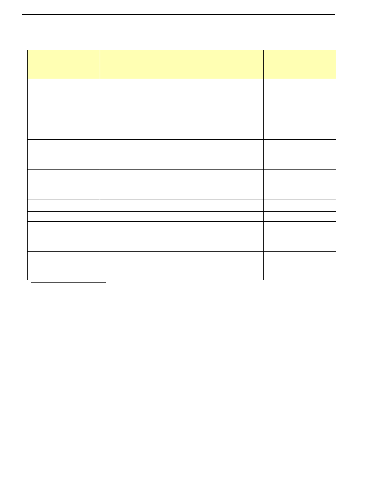
TABLE 1. ADAM Master Controller Card (MC-ADAM 9002-7514-100) DIP Switch Settings (S1)
Description
On=Closed, Off=Open
Switch No.
AZedit baud rate select
1
OFF: 9600
b
ON: 38.4
Key Incoming Message Option
2
OFF: Normal Operation
c
ON: All callers displayed in Incoming Messages window
Keypanel “busy” and “in-use” flash
3
OFF: Enable
d
ON: Disable
Trunk Master baud rate select
4
OFF: 38.4K baud
e
ON: 9600 baud
5
Clock Monitor
f
6 Not Used (set to OFF) OFF
Primary / Secondary ADAM card frame select
7
OFF: Secondary Frame
g
ON: Primary Frame
Test ON / OFF
8
OFF: Normal Operation
ON: Test Mode
a
Default Setting
On=Closed, Off=Open
ON
OFF
OFF
OFF
ON
OFF
a. Always set the DIP switches the same on both the main and backup controller cards.
b. The default setting of 9600 baud is compatible with the default setting for the AZedit configuration software. Alternatively, 38.4k
baud will provide faster uploads and downloads, but the cable from the ADAM Frame to the PC must be kept to a length less than
10ft (3m), and some older PCs may not operate reliably at this speed.
c. Normally, when a call is received by a keypanel, the keypanel checks for a talk key assigned to the caller. If there is no talk key
assigned, the display above that key will flash. If no key is assigned, the caller’s name will appear in the Incoming Messages
window. Some intercom systems may have many keypanels that do not have alpha-numeric displays. In this case, it may be
preferable to have all callers names appear in the Incoming Messages window.
d. The in-use flash is indicated by a slow and continuous flashing display above a keypanel talk key. It is provided for IFBs, ISOs and
trunk lines. It occurs, for example, on all keypanels that have keys assigned to a particular IFB, when that IFB is in-use by any
keypanel.The displays will continue to flash until the IFB is no longer in-use. Any user could activate their talk key to talk to the IFB
while the display is flashing, but they may interrupt a conversation that is in progress.
The busy flash is indicated by a display that alternates between the normal key assignment and a double asterisk (**) when the talk
key is pressed. A “busy” flash occurs when a keypanel tries to talk to an IFB or trunk line that is currently in-use by another
keypanel that has a higher IFB or trunking priority . When a busy flash is indicated, the user cann ot talk to the destination assigned to
the talk key.
e. 38.4K baud is the normal data rate for communication with a local trunk mast. 9600 baud may be selected when the intercom system
is connected to a remote trunk master over some form of long-distance connection (modems, partial T1, etc.). However, expect large
response delays when using 9600 baud. If this is not acceptable, other methods of connection using additional equipment may be
required.
f. Set to ON only for Altera chip versions 4.1 and higher. Provides enhanced error correction for the bus clock. Leave in OFF position
for Altera versions below 4.1.
g. The primary frame is the one which is connected to th e system configuration computer, trunk master, UIO-256s, PAPs, etc. When a
single ADAM frame is used alone, it must be set as the primary frame. When several ADAM frames are interconnected using bus
expanders, one of the frames must be set as the primary frame, and all other frames must be set as secondary frames.
12
Page 17
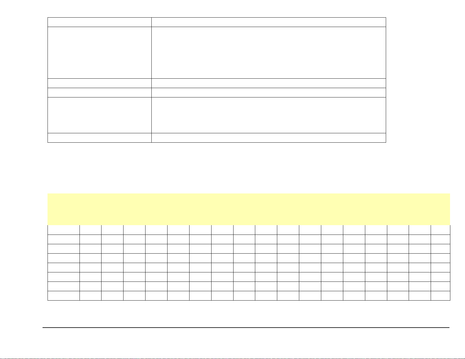
TABLE 2. MCII-e Factory set DIP Switch Settings
DIP Switch 1 Debug Only! Must be in OPEN position.
Sets the baud rate for AZedit serial connection via J1.
By default, AZedit is set for COM1 and 38,400 kbps (38.4k). The baud rate set in AZedit must
match the baud rate setting of the Master Controllers in ADAM.
DIP Switch 2
Default: OPEN
OPEN: 9600 baud
CLOSED: 38.4k baud
DIP Switch 3, 4, and 5 Reserved, keep in OPEN position.
DIP Switch 6 Debug Only! Must be in OPEN position.
Determines the Master / Slave Frame in a multi-frame system
DIP Switch 7
Default: CLOSED
OPEN: Slave Frame
CLOSED: Master Frame
DIP Switch 8 Debug Only! Must be in OPEN position.
WARNING: DIP Switches 1, 6, and 8 should always be left in the OPEN position. These are reserved for debugging and can have unintended consequences if not left in the
OPEN position.
TABLE 3. Relationship between Audio Input/Output Cards, Intercom Ports, and Logical Keypanel Numbers
Intercom Port Numbers, Grouped by Audio I/O Card Numbers
Logical
Keypanel
AIO1AIO2AIO3AIO4AIO5AIO6AIO7AIO8AIO9AIO10AIO11AIO12AIO13AIO14AIO15AIO16AIO
Number
1 1 9 1725334149576573818997105113121129
2 2 10 18 26 34 42 50 58 66 74 82 90 98 106 114 122 130
3 3 11 19 27 35 43 51 59 67 75 83 91 99 107 115 123 131
4 4 12 20 28 36 44 52 60 68 76 84 92 100 108 116 124 132
5 5 13 21 29 37 45 53 61 69 77 85 93 101 109 117 125 133
6 6 14 22 30 38 46 54 62 70 78 86 94 102 110 118 126 134
7 7 15 23 31 39 47 55 63 71 79 87 95 103 111 119 127 135
8 8 16 24 32 40 48 56 64 72 80 88 96 104 112 120 128 136
NOTE: For AIO-16 cards, see the AIO-16 User Manual (p/n 9350-7726-000).
17
13
Page 18
Intercom Port Connections
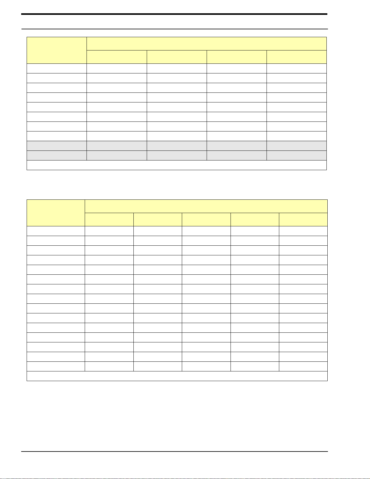
TABLE 4. Address DIP Switch Settings for KP-95, 96, 97, 98 Keypanels and the TIF
Address DIP Switch Setting
Logical Keypanel
Number
SW4 SW5 SW6 SW7
1DOWNUP UP UP
2 UP DOWN UP UP
3 DOWN DOWN UP UP
4UPUPDOWNUP
5DOWNUPDOWNUP
6 UP DOWN DOWN UP
7 DOWN DOWN DOWN UP
8 UPUPUPDOWN
9 DOWN UP UP DOWN
10 UP DOWN UP DOWN
NOTE: The shaded area is for CS9xxx system address only!
TABLE 5. CDP-950 Intercom Range Selection
DIP Switch Number
Ports Controlled
4 5 6 7 8
1 Only Open Closed Closed Closed Closed
1 & 2 Closed Open Closed Closed Closed
1 & 3 Open Open Closed Closed Closed
1 & 4 Closed Closed Open Closed Closed
1 & 5 Open Closed Open Closed Closed
1 & 6 Closed Open Open Closed Closed
1 & 7 Open Open Open Closed Closed
1 & 8 Closed Closed Closed Open C l osed
2 & 8 Closed Open Closed Closed Open
3 & 8 Open Open Closed Closed Open
4 & 8 Closed Closed Open Closed Open
5 & 8 Open Closed Open Closed Open
6 & 8 Closed Open Open Closed Open
7 & 8 Open Open Open Closed Open
8 Only Closed Closed Closed Open Open
#1 refers to the lowest numbered port on any given Audio Input/Output Card; #8 refers to the highest
14
Page 19

KP-32 Addressing
KP-32 Addressing
A rotary switch is used to indicate the logical port address the keypanel is to use when communicating with the
Matrix. The switch is read continuously through polling by the matrix. If the port address is changed, the new
address is effective immediately.
NOTE: The address pot, by default is shipped with an invalid address to ensure that there are no conflicts with
existing keypanels. It is important to set the address port for the KP-32 keypanel for it to function properly.
The Address switch has a white pointer - pointed at 7. This indicates port 7 or the given AIO card. Determine the proper
setting using Table 6.
TABLE 6. Program Assign Panel DIP Switch Settings for Panel Number
ID SW1 SW2 SW3 SW4
0 Open Open Open Open
1 Close Open Open Open
2 Open Close Open Open
3 Close Close Open Open
4OpenOpenCloseOpen
5 Close Open Close Open
6 Open Close Close Open
7 Close Close Close Open
8 Open Open Open Close
9 Close Open Open Close
10 Open Close Open Close
11 Close Close Open Close
12 Open Open Close Close
13 Close Open Close Close
14 Open Close Close Close
15 Close Close Close Close
TABLE 7. UIO-256 DIP Switch Settings for Input/Output Range
DIP Switch Settings
I/O
Range
1-16
a
1 2 3 4 5 6 7 8
Open Closed Open Open Open Open Open Closed
17-32 Open Closed Open Closed Open Open Open Closed
33-48 Open Closed Open Open Closed Open Open Closed
49-64 Open Closed Open Closed Closed Open Open Closed
a. Default
15
Page 20

Intercom Port Connections
TABLE 8. UIO-256 Relay Outputs Connector (J5)
PIN
Relay Output Numbers
a
NC Contact Common NO Contact
1/17/33/49 38 13 40
2/18/34/50 39 14 15
3/19/35/51 41 16 43
4/20/36/52 42 17 18
5/21/37/53 44 19 46
6/22/38/54 45 20 21
7/23/39/55 47 22 49
8/24/40/56 48 23 24
9/25/41/57 26 1 28
10/26/42/58 27 2 3
11/27/43/59 29 4 31
12/28/44/60 30 5 6
13/29/45/61 32 7 34
14/30/46/62 33 8 9
15/31/47/63 35 10 37
16/32/48/64 36 11 12
a. Dependent on UIO-256 DIP Switch SW1 Settings for Input/Output Range as summarized in Table 7.
The relay contacts are rated for 0.5A at 120 VAC; 1A at 24 VDC; 0.3A at 60 VDC
TABLE 9. UIO-256 Opto-Isolated Inputs Connectors (J7)
Relay Output Numbers
a
DC Control Input “-”
1/17/33/49 9 34
1/18/34/50 10 35
3/19/35/51 11 36
4/20/36/52 12 37
5/21/37/53 13 38
6/22/38/54 14 39
7/23/39/55 15 40
8/24/40/56 16 41
9/25/41/57 1 26
10/26/42/58 2 27
11/27/43/59 3 28
12/28/44/60 4 29
13/29/45/61 5 30
14/30/46/62 6 31
15/31/47/63 7 32
16/32/48/64 8 33
PIN Numbers
DC Control Input “+”
(50 to 30 VDC)
16
Page 21

KP-32 Addressing
a. Dependent on UIO-256 DIP Switch SW1 Settings for Input/Output Range as summarized in Table 7.
Inputs will sink 100mA max at a maximum input voltage of +18 VDC
For operation from an external DC voltage source, connect the external control voltage to the “+” pin, and connect the exte rnal common to the “-
” pin.
The UIO265 also has an internal 18 VDC source, which is available at pins 18 to 22. Ground is available at pins 24 and 25. To use the internal 18
VDC source, ground the “-” pin for the desired control input, then use an external switch to connect from the 18 VDC internal source to the “+”
input pin.
TABLE 10.
Intercom
Port No.
Intercom System Planning Worksheet
ADAM
Audio I/O
Card No.
Logical
Keypanel
Number
111
212
313
414
515
616
717
818
921
10 2 2
11 2 3
12 2 4
13 2 5
14 2 6
15 2 7
16 2 8
17 3 1
18 3 2
19 3 3
20 3 4
21 3 5
22 3 6
23 3 7
24 3 8
25 4 1
26 4 2
27 4 3
28 4 4
29 4 5
30 4 6
31 4 7
AZedit
Alpha
AZedit
Alias
Description
(Device Type, Location, User, etc.)
17
Page 22

Intercom Port Connections
TABLE 10. Intercom System Planning Worksheet
Intercom
Port No.
Audio I/O
Card No.
32 4 8
33 5 1
34 5 2
35 5 3
36 5 4
37 5 5
38 5 6
39 5 7
40 5 8
41 6 1
42 6 2
43 6 3
44 6 4
45 6 5
46 6 6
47 6 7
48 6 8
49 7 1
50 7 2
51 7 3
52 7 4
53 7 5
54 7 6
55 7 7
56 7 8
57 8 1
58 8 2
59 8 3
60 8 4
61 8 5
62 8 6
63 8 7
64 8 8
65 9 1
66 9 2
67 9 3
68 9 4
69 9 5
ADAM
Logical
Keypanel
Number
AZedit
Alpha
AZedit
Alias
Description
(Device Type, Location, User, etc.)
18
Page 23

KP-32 Addressing
TABLE 10. Intercom System Planning Worksheet
ADAM
Intercom
Port No.
Audio I/O
Card No.
70 9 6
71 9 7
72 9 8
73 10 1
74 10 2
75 10 3
76 10 4
77 10 5
78 10 6
79 10 7
80 10 8
81 11 1
82 11 2
83 11 3
84 11 4
85 11 5
86 11 6
87 11 7
88 11 8
89 12 1
90 12 2
91 12 3
92 12 4
93 12 5
94 12 6
95 12 7
96 12 8
97 13 1
98 13 2
99 13 3
100 13 4
101 13 5
102 13 6
103 13 7
104 13 8
105 14 1
106 14 2
107 14 3
Logical
Keypanel
Number
AZedit
Alpha
AZedit
Alias
Description
(Device Type, Location, User, etc.)
19
Page 24

Intercom Port Connections
TABLE 10. Intercom System Planning Worksheet
Intercom
Port No.
Audio I/O
Card No.
108 14 4
109 14 5
110 14 6
111 14 7
112 14 8
113 15 1
114 15 2
115 15 3
116 15 4
117 15 5
118 15 6
119 15 7
120 15 8
121 16 1
122 16 2
123 16 3
124 16 4
125 16 5
126 16 6
127 16 7
128 16 8
129 17 1
130 17 2
131 17 3
132 17 4
133 17 5
134 17 6
135 17 7
136 17 8
ADAM
Logical
Keypanel
Number
AZedit
Alpha
AZedit
Alias
Description
(Device Type, Location, User, etc.)
20
Page 25

CHAPTER 3
Device Connections
Connections to the ADAM Frame
An ADAM Intercom System can be setup in a variety of configurations to meet different user requirements. Several common
variations are illustrated in the system drawings starting on page 33.
Configuration Computer Connection and Check
Use an RS-232 serial cable to connect from J1 of the XCP-ADAM-MC Breakout Panel to COM1 or COM2 of the
configuration PC. For cable wiring details, refer to “ADAM-807 ADAM Intercom System AZedit to PC RS-232-C Cable” on
page 51.
Insert the AZedit software CD into the computer. Follow the instructions to load AZedit onto the PC. Note, the computer
should have at least 2 MB of extended memory (4 MB preferably).
If the link between the computer and intercom system is functioning properly, the current intercom system configuration
should upload (even if nothing has yet been programmed). ONLINE mode should appear at the lower right of the computer
screen. If not, check the cable wiring and the connection between the computer and the intercom system.
NOTE: By default, the AZedit configuration program uses COM1 and 38400 baud for communication between the computer
and intercom system. COM2 and/or 9600 baud, USB, Network connections are selectable as options in AZedit
(Options>Communications). When operating at 38.4k baud, DIP switch number 1 must be set to the ON position on both the
main and backup master controller cards in the ADAM frame, see “ADAM Master Controller Card (MC-ADAM 9002-7514-
100) DIP Switch Settings (S1)” on page 12 or “MCII-e Factory set DIP Switch Settings” on page 13, depending on the type of
Master Controller you are using.
Program Assign Panel (PAP) Installation
General
Up to 15 PAPs can be connected to the intercom system. Each PAP has DIP switches to assign it as panel number 1 through
15, and to select either a low or high IFB range. As supplied, PAPs expect all program sources to be connected to sequential
intercom ports of the intercom system starting with port #1. The options and default setting for the P AP series are summarized
in the following table:
21
Page 26

Device Connections
TABLE 11. PAP Addresses
IFB Range
Model
PAP-940 1-24 1-4 1-40 41-80
PAP-950-50 1-50 1-4 1-50 51-100
PAP-951 1-8 1-4 1-12 13-24
PAP-952 1-16 1-4 1-24 25-48
The intercom port addresses for program input, as well as the low and high ranges for IFB output, are stored in EPROM
memory in the PAP. In some cases, it may be desirable to control program sources and IFB ranges other than those allowed by
the defaults. In such cases, new custom EPROMs can be programmed as needed. Contact your intercom system dealer for
further information.
Default Ports for
Program Input
Panel No.
(Default = 1)
Low (Default) High
Connecting a Single PAP
Connect a single PAP to J3 of the Master Controller Breakout Panel as shown in ADAM-101 through ADAM-108
interconnect diagrams on starting on page 35. Use and RS-485 data cable wired as shown in the ADAM-809 installation
drawing on page 53. Connect power to the AC mains connector.
Connecting Additional PAPs
Connect any additional PAPs by wiring them in parallel with the first PAP.
Change the panel number DIP switches in all but one of the PAPs. To do this, remove the covers from the PAP and locate the
8-position DIP switch block on the PMC-15 circuit board. By default, all PAPs are supplied with DIP switches #1 and #2 set
for panel number 1. Reset the switches as shown in Table 6 on page 15, so that each PAP has a unique panel number.
By default, all PAP systems are supplied with the lower of two ranges of IFBs selected. For example, a PAP-952 is set by
default to work with IFB numbers 1 to 24. If a second PAP-952 is connected, it can be reset to work with IFB numbers 25 to
48, if desired.
NOTE: DIP switches 4-8 in PAP systems are not used and their position does not matter.
Programming IFB Defaults to Initialize PAPs
Before a PAP can reassign program inputs, a default configuration for each IFB must first be setup using AZedit. See
“Creating an IFB”.
Note, it is not necessary to have any program sources or output stations connected to setup the IFBs.
Checking PAP Operation
Status of a PAP can be checked by selecting PAP from the Status menu in AZedit.
Alternatively, it is possible to check PAP operation using the XPT (Crosspoint Table) in AZedit. When you select “Force and
Inhibit” from the System menu in AZedit, a port pick list appears. Select one of the IFB output ports. A “Connecting Ports”
table for that port appears. As program sources are reassigned on the PAP front panel, the changes can be viewed in the table
by pressing the ENTER key. As each new program source is connected, a check mark appears next to that port in the table.
22
Page 27

Connections to the ADAM Frame
PAP-32 Program Assign Panel
The PAP-32 connects to J3 on the ADAM system, port 902 on an ADAM CS system. The baud rate, as will all UIO-256, PAP,
and LCP-102 devices is fixed at 76.8k baud.
A cable must be made to connect the PAP-32 to the system. See the following figures for the proper cabling diagram.
FIGURE 1. PAP D-sub Cable Diagram
FIGURE 2. PAP-32 RJ-12 Cable
23
Page 28

Device Connections
Viewing the Program Source for an IFB
Press an IFB destination key which has an IFB assignment (i.e., is not blank/). The IFB key’s lower LED will be turned on
solid red.
If the specified IFB has a program source, the lower LED for the key which has that program source assigned will turn on solid
red for as long as the IFB key is held on. If the program source for that IFB does not appear on any of the source keys, the
source will be displayed in the scroll window, and the scroll window’s lower LED will turn on solid red.
If the specified IFB key is press and does not have a program source, no indication is shown on the source keys.
If an IFB destination key is pressed and the key does not have a program source, no indication is shown on the source keys.
If an IFB destination key is pressed and the key does not have an assignment, the key press is ignored.
If an IFB key is pressed and it does not have an output bus defined (in AZedit), the LED turns on solid green to indicate the
program input for that IFB cannot be changed.
Viewing What IFBs a Program Source Feeds
Press a program source key. The lower LED for that key will be turned on solid red. Any IFB keys which have that program
source assigned will turn on solid red, for as long as the source key is held on.
The program source may also feed other IFBs which are not assigned on the PAP-32. No indication is provided for those IFBs.
Assigning Source and IFB Keys
NOTE: When a key is programmed by entering a programming sequence or by copying the scroll key to it, its LED turns on
green to indicate the key is being programmed. The key must be released and pressed again in order to see information about
its assignment (e.g., for an IFB key, to see what program input is feeding it).
Direct Assignment
To directly assign a source key, enter “1” (‘NUM’), followed by the IFB number (1-3 digits), followed by “PGM”, and tap a
source key. The key will be assigned to that port. A port number of 0 is used to clear any existing assignments.
To directly assign an IFB key, enter “0:, “2” (“Function-IFB”), followed by the IFB number (1-3 digits) followed by “PGM”,
and tap a destination key. The key will be assigned to that IFB. An IFB number of 0 is used to clear any existing assignments.
Scrolling
Press either the “Source” key on the keypad (to scroll through available program sources) or the “Dest” key (to scroll through
IFBs). The first item of the requested list is shown in the scroll window. The scroll keys can be used to step through the list.
Normally, scrolling is one item at a time. Press “5” (“Prefix”) enters prefix scroll mode, in which groups of alphas with the
same 2-character prefix are skipped. Pressing CLR or PGM cancels prefix scroll mode and reverts to normal scroll mode.
When the requested assignment is displayed, press 7 (copy), and then tap the key to which the assignment is to be copied.
Alternatively, for program sources only, the key can be used while it is in th e scroll windo w, without copying. The scroll key
can be cleared, if desired, by pressing up briefly.
When scrolling through program sources, the only ports which are displayed are those for which the “LCP-102 scroll enable”
box is checked in AZedit. By default, the first 200 ports are LCP-102 scroll enabled. However, if a port has been assigned to a
key, the assignment remains even if the port is subsequently scroll restricted.
24
Page 29

UIO-256 Input/Output Frame
UIO-256 Input/Output Frame
Connecting a single UIO-256 Frame
1. Connect a single UIO-256 to J3 of the Master Controller Breakout Panel, as shown in ADAM-101 through ADAM-108
interconnect diagrams starting on page X. Use a RS-485 data cable wired as shown in the ADAM -809 installation drawing
on page 53. If a PAP is also being used, it may be wired to the same connector. Alternatively, use a punch block or other
connector system.
2. Set the SW-1 DIP switch on the back of the UIO-256 to select a range 1-16, as shown in Table 7 on page 15.
The SW-2 DIP switches are not used, and their positions do not matter.
3. Connect relay outputs to external devices using the relay outputs connector, J5.
The J5 connector pinout is shown in Table 8 on page 16.
4. Connect the input devices using the opto-isolator connector, J7.
The connector pinout is shown in Table 9 on page 16.
Connecting Additional UIO-256 Frames
1. Up to 15 additional UIO-256 frames may be connected in a parallel bus configuration using the 15-pin ribbon cables
provided.
2. Connect the J3 output of the ADAM MC to the UIO-256 via J2 on the UIO-256.
3. Connect J2 output of the first UIO-256 to the J2 input of the second UIO-256.
4. Connect the J2 output of the second UIO-256 to the J2 input of the third.
Repeat as necessary
5. Set the SW1 DIP switches on each UIO-256 to select a unique panel number as summarized in Table 7 on page 15.
6. Connect to the opto-isolator outputs and relay inputs as for the first UIO-256.
Programming the UIO-256
Each opto-isolator input is assignable in the GPI Assignments table of AZedit. The GPI Assignment table allows you to
simulate a key on a keypanel at a particular intercom port, regardless of whether or not there is an actual keypanel connected to
that port.
If an input has been assigned to a key, it is then necessary to define a device to be activated by that key. This is accomplished
in the keypanel edit screen for the port to which the digital input was assigned.
The UIO-256 relay outputs are programmed using the GPI Output Edit screen in AZedit.
25
Page 30

Device Connections
Connecting to the SSA-324
General Description
The SSA-324 is a System-to-System Adapter (or interface). It interconnects the voice signals between different types of
intercom systems. In addition, it can optionally interconnect intercom systems. Also, it can optionally interconnect “Calls” or
tally signals between systems. Each SSA-324 includes two, 2-wire to 4-wire converters. The 4-wire interface can deliver and
accept high-level signals such as those from the McCurdy intercom system. An SSA-324 carries two voice channels when
used as dual 2-wire to 4-wire interfaces, and one voice channel when functioning as a 2-wire to 2-wire interface.
Installation
Mechanical Installation
The SSA-324 can be installed in 3 ways:
• a single unit mounted in half rack space using an optional Model MCP2 Kit for rack mounting a single unit.
• two SSA-324 power supplies mounted side-by-side using the optional MCP1 Kit for rack mounting two units side-by-side.
• free standing using the optional MCP8 Kit for adding side channels for non-rack mounting portable use.
Electrical Installation
The connection for t6he headset used to setup the interface is on the front panel, all other connections are on the rear panel.
On the rear panel, on System A the 2-wire connection is at J101, while on System B it is a J102. These are XLR-3-31 (female)
type connectors. System A and B 4-wire connections are both at TB1 and J103. J103 also contains connections to the options
card, when installed. Low voltage alternating current power is applied to J104 (16 volts, AC).
RTS
Unbalanced
Audiocom
Balanced
a
Clear-Com
Unbalanced
b
CH1 2 2, 3 3
CH2 3 - Com111
a. S101 (System A) and/or S102 (System B) set to IN position for balance
operation.
b. If option board installed and Clear-Com call light operation is required,
move jumper W103 (System A) an/or jumper W203 (System B) on
motherboard to 2, 3 position. Jumper J103-7, 20 for System A, and/or
J103-12/25 for System B.
26
Page 31

Connecting to the SSA-324
TB1 Four Wire Connections
System A System B
TB1- TB1-
Audio In Hi 1 5
Audio In Lo 2 6
Audio Out Hi 3 8
Audio Out Lo 4 8
J104 Power Input
Earth 1
16VAC 2
16VAC 3
No Conn. 4
J103 I/O
1Earth
2 4-wire Audio In Hi, System A
15 4-wire Audio In Lo, System A
3 4-wire Audio Out Hi, System A
16 4-wire Audio Out Lo, System A
4 4-wire Audio In Hi, System B
17 4-wire Audio In Lo, System B
5 4-wire Audio Out Hi, System B
18 4-wire Audio Out Lo, System B
6 Call Send GND (A)
19 Call Send Hi (A)
7 DC Call Sig En GND (A)
20 DC Call En Hi (A)
8 Relay Contact NO (A)
9 Relay Contact COM (A)
21 Relay Contact NC (A)
22 Relay Contact NO (B)
23 Relay Contact COM (B)
10 Relay Contact NC (B)
11 Call Send GND (B)
24 Call Send Hi (B)
12 DC Call Sig En GND (B)
25 DC Call Sig En Hi (B)
27
Page 32

Device Connections
Front Panel Dyn. Mic Headset Connector
1Mic Lo
2Mic Hi
3 Headphone Com
4 Headphone Hi
Motherboard Test Signal Jumper
Place jumper on W2 for tone test signal, W3 for voice test signal. Test signal used with headset and front panel nulling
adjustments to null return 2-wire signal.
Operation
Controls and Connections
Front Panel Switches
1. Channel Select switch, CH1 out / CH2 in, Sys A.
2. Press momentary switch for nulling System A, 2-wire
3. Channel Select switch, CH1 out / CH2 in, System B
4. Press momentary switch for nulling System B, 2-wire
Connectors
5. XLR-4-31 Female 4-pin headset connector (DYN MIC HEADSET)
Controls
6. Monitor headphone level (VOLUME)
Indicator
7. Indicator (Power) green LED
Controls
8. LEVEL TO RTS, System A
9. LEVEL FROM RTS, System A
10. DUCK Level, System A
11. Inductive (LOW) null, System A
12. Resistive (MEDium) null, System A
13. Capacitive (HIgh) null, System A
14. LEVEL TO RTS, System A
15. LEVEL FROM RTS, Syst em A
16. DUCK Level, System A
17. Inductive (LOW) null, System A
18. Resistive (MEDium) null, System A
19. Capacitive (HIgh) null, System A
28
Page 33

Connecting to the SSA-324
Rear Panel
Switches
Unbalance (Out) Balance (In) / Select Two-wire, System A
Unbalance (Out) Balance (In) / Select Two-wire, System B
Operation Nulling
Preset Controls as follows:
To/From RTS Set to Midway
Duck Level Set to CW
Low Set to Midway
Med Set to Midway
Hi Set to CW
Volume 10 o’clock
Press Test Switch
1. If test signal tone, adjust Med for null, then Hi, then Low. If test signal voice, say “ahhhhh” into microphone, adjust Med
for null, then Hi, then Low.
2. Release Test Switch
Level Setting
1. Have Talkers 1 and 2 on 4-wire system, Talkers 3 and 4 on 2-wire system. Adjust To / From RTS Controls so that all
Talkers can hear each other at about the same level regardless of which system they are on.
Duck Setting
1. Adjust Duck Level only if full duplex operation is not possible because of feedback. Adjust Duck Level carefully from CW
towards CWW. Only a very small amount of ducking should be used.
29
Page 34

Device Connections
Connecting to an SSA-424
General Description
The SSA-424 Dual Digital Hybrid interfaces two, 2-wire intercom lines to two, 4-wire intercom lines. Unlike earlier analog
hybrids, the SSA-424 features advanced digital signal processing to achieve automatic nulling of the 4-wire lines. Plus, each
hybrid features convenient peak-reading level meters to quickly match the levels between the lines that are being interfaced.
The result is an easy and accurate setup. With the SSA-424, all need for test tones, nulling adjustments, and ducking
adjustments have been eliminated.
4-Wire Audio Connections for ADAM, ADAM CS or Zeus
1. Use standard 9-pin or RJ-12 keypanel cables.
2. Connect from one port of your intercom system to J2A or J3A (System A connection) on the back of the SSA-424.
3. Connect from another port to J2B or J3B (System B connection).
4. on the SSA-424 front panel, set the 4W LEVEL REF SEL switches to the +8dB position.
Audio Connections for Other 4-Wire Communications Systems
1. Construct 9-pin or RJ-11 cables to connect from your 4-wire system to the SSA-424. To to the System A hybrid, use either
J2A or J3A; for the System B hybrid, use either J2B or J3B.
Pin Connections are as follows:
9-pin Connection
Connector Type (on SSA-424 end of cable): 9-pin male D-sub
Pin 1 No Connection
Pin 2 No Connection
Pin 3 No Connection
Pin 4 Balanced Audio + output (to 4-wire system)
Pin 5 Balanced Audio - output (to 4-wire system)
Pin 6 No Connection
Pin 7 Balanced Audio - input (from 4-wire system)
Pin 8 Balanced Audio + input (from 4-wire system)
Pin 9 No Connection
RJ-12 Connection
Connector Type (on SSA-424 end of cable)): RJ-12 plug
Pin1 No Connection
Pin 2 Balanced Audio + input (to 4-wire system)
Pin 3 Balanced Audio + output (to 4-wire system)
Pin 4 Balanced Audio - output (to 4-wire system)
Pin 5 Balanced Audio + output (to 4-wire system)
Pin 6 No Connect ion
2. On the SSA-424 front panel, set the 4W LEVEL REF SEL switches to the position which most closely matches the audio
input and output levels of your 4-wire system. If you don’t know the levels, select +4 dB. for the time being.
30
Page 35

Connecting to an SSA-424
4-Wire Call Signal Connections
NOTE: These connections will require the call signal option. Part Number 9002705500.
Call Signal Connections for ADAM, ADAM CS, and Zeus
You can use the General Purpose Interface (GPI) connector to interface the call signals. The pin-out of the connector is the
same for all of these intercom systems.
ADAM GPI Connector: XCP-ADAM-MC, J11
ADAM CS GPI Connector: J903
Zeus GPI Connector J27
If you intercom system is equipped with a UIO-256 Universal Input / Output Frame, you can also use that for connections.
As an alternative to using the GPI, you can use external components to send and receive call signals.
Call Signal Connections for Other 4-Wire Communications Systems
4-wire Call Send and Call Enable/Inhibit
The SSA-424 accepts a switch-contact input from the 4-wire system and then generates a call signal output to the 2-wire
system. The SSA-424 also accepts an option switch contact input to enable or inhibit call signalling between the 4-wire and 2wire systems.
4-Wire Cal l Receive
The SSA-424 receives call signals from the 2-wire system, then converts this to relay contact closure for use as a 4-wire call
receive indication. The SSA-424 also provides +5 VDC which can be connected to the relay contacts to generate a DC output
signal instead of a contact closure.
The SSA-424 power indicator flashes whenever a call signal is received from either 2-wire line. This can be used as an
incoming call indication for the 4-wire system, if desired, and the level display should provide an indication of which line is
calling.
31
Page 36

Device Connections
32
Page 37

CHAPTER 4
Drawings
33
Page 38

Drawings
34
Page 39

FIGURE 3. ADAM-101 ADAM Intercom System XCP-40-RJ11 Interconnect Diagram
ADAM Installation Manual - 35
Page 40

FIGURE 4. ADAM-102 ADAM Intercom System XCP-40-DB9 Interconnect Diagram
ADAM Installation Manual - 36
Page 41

FIGURE 5. ADAM-103 ADAM Intercom System XCP-955 / Jack fields / SCSI Interconnect Diagram
ADAM Installation Manual - 37
Page 42

FIGURE 6. ADAM-104 ADAM Intercom System XCP-955 / Jack fields / RJ Interconnect Diagram
ADAM Installation Manual - 38
Page 43

FIGURE 7. ADAM-105 ADAM Intercom System XCP-955 / Jack fields / SCSI Interconnect Diagram
ADAM Installation Manual - 39
Page 44

FIGURE 8. ADAM-106 ADAM Intercom System XCP-955 / Jack fields / RJ Interconnect Diagram
ADAM Installation Manual - 40
Page 45

FIGURE 9. ADAM-107 ADAM Intercom System XCP-954-48 / Jack fields / SCSI Interconnect Diagram
ADAM Installation Manual - 41
Page 46

FIGURE 10. ADAM-108 ADAM Intercom System XCP-954-48 / Jack fields / RJ Interconnect Diagram
ADAM Installation Manual - 42
Page 47

FIGURE 11. ADAM-301 ADAM Intercom System Matrix Frame Layout - AIO-8
ADAM Installation Manual - 43
Page 48

FIGURE 12. ADAM Intercom System Matrix Frame Layout - AIO-16
RESET
23
22
21
20
19
18
17
16
15
14
13
12
11
10
9
8
7
6
5
4
3
2
1
0
MCIIe
SYSTEM
CONTROLLER
RESET
TM
TM
23
22
Ports 137 through 272
21
20
19
18
17
16
15
14
13
12
11
10
9
8
7
6
5
4
3
2
1
0
1
MCIIe
SYSTEM
CONTROLLER
2
Ports 1 through 136
1
2
PORTS NOT USED
Bottom Group
137-144
SLOT 1
8 ports (1-8)
+2.1V
+5V
+15V
-15V
POWER
GOOD
+2.1V
+5V
+15V
-15V
Ports 137 through 272
8 ports (169-176)
Top Group
161-168
153-160
PORTS NOT USED
PORTS NOT USED
145-152
137-144
PORTS NOT USED
PORTS NOT USED
Bottom Group
SLOT 1
8 ports (1-8)
Bottom Group
SLOT 2
8 ports (9-16)
Bottom Group
SLOT 3
8 ports (17-24)
Bottom Group
SLOT 4
8 ports (25-32)
Bottom Group
SLOT 5
8 ports (33-40)
Ports 1 through 136
23
22
21
20
19
18
17
16
15
14
13
12
11
10
9
8
7
6
5
4
3
2
1
0
MCIIe
SYSTEM
CONTROLLER
POWER
GOOD
RESET
TM
1
2
RESET
23
22
21
20
19
18
17
16
15
14
13
12
11
10
9
8
7
6
5
4
3
2
1
0
MCIIe
SYSTEM
CONTROLLER
TM
1
2
RESET
RTS™
23
22
21
20
19
18
17
16
15
14
13
12
11
10
9
8
7
6
5
4
3
2
1
0
1
AIO-16
2
AIO-16 Front
Card Plate
with LED Board
RESET
AIO-16
RTS™
AIO-16 Front
Card Plate
(Standard)
RESET
TM
23
22
21
20
19
18
17
16
15
14
13
12
11
10
9
8
7
6
5
4
3
2
1
0
1
MCIIe
SYSTEM
CONTROLLER
2
MCII-e Front Card
Plate, Master Controller
J2
J1
AIO-16 Back
Card Plate,
SCSI
J2
J1
AIO-16 Back
Card Plate,
MDR
ADAM Installation Manual - 44
Page 49

FIGURE 13. ADAM-801 ADAM Intercom System Audio Input / Output / Data 50 Pins SCSI-2 Cable
ADAM Installation Manual - 45
Page 50

FIGURE 14. ADAM-802 ADAM Intercom System Audio Input / Output 25 Pairs Telco Cable
ADAM Installation Manual - 46
Page 51

FIGURE 15. ADAM-803 ADAM Intercom System Audio Input / Output 25 Pairs to RJ-45 Cable
ADAM Installation Manual - 47
Page 52

FIGURE 16. ADAM-804 ADAM Intercom Matrix RJ11 to 50 Pins Telco Translation Cable
ADAM Installation Manual - 48
Page 53

FIGURE 17. ADAM-805 ADAM Intercom Matrix DB9 to 50 Pins Telco Translation Cable
ADAM Installation Manual - 49
Page 54

FIGURE 18. ADAM-806 ADAM Intercom System Master Controller 68 Pins SCSI-2 Cable
ADAM Installation Manual - 50
Page 55

FIGURE 19. ADAM-807 ADAM Intercom System AZedit to PC RS-232-C Cable
ADAM Installation Manual - 51
Page 56

FIGURE 20. ADAM-808 ADAM Intercom System Matrix to Trunk aster RS-485/ RS232C Cable
ADAM Installation Manual - 52
Page 57

FIGURE 21. ADAM-809 ADAM Intercom System UIO-256 and PAP Cables
ADAM Installation Manual - 53
Page 58

1 234 5 6
CONTACTS
FIGURE 22. Intercom Station Cables
(VIEW FROM CABLE ENTRANCE)
RJ11 MOD PLUG
3 TWISTED PAIR TELEPHONE CABLE
PAIR 1: AUDIO TO MATRIX
PAIR 2: AUDIO FROM MATRIX
PAIR 3: DATA
1
2
3
4
5
AUDIO FROM MATRIX +
AUDIO TO MATRIX +
AUDIO TO MATRIX -
AUDIO FROM MATRIX -
6
RJ-11 Intercom Cable
123456
DATA -
DATA +
LATCH
2
8
4
5
7
1
DE-9S (Female)
To Station Breakout Panel
1
2
6
4
5
9
7
8
3
9-Pin D-Sub Intercom Cable
DE-9S (Male)
To Intercom Station
-
1
+
2
6
-
4
+
5
9
-
7
+
8
3
TO INTERCOM
MATRIX
RJ11
1
2
3
4
5
6
DATA -
AUDIO FROM MATRIX +
AUDIO TO MATRIX +
AUDIO TO MATRIX -
AUDIO FROM MATRIX -
DATA +
RJ-11 to 9-Pin D-Sub Intercom Cable
For Connection of the TIF to an RJ-11
Style Station Breakout Panel
TO TIF
DE-9P
(MALE)
2
8
4
5
7
1
TO STATION BREAKOUT PANEL
IN FIRST INTERCOM SYSTEM
DE-9S
(Female)
1
2
6
4
5
9
8
7
3
TO STATION BREAKOUT PANEL
IN SECOND INTERCOM SYSTEM
DE-9S
(Male)
1
2
6
+
4
-
5
9
+
8
-
7
3
TO STATION BREAKOUT PANEL
IN FIRST INTERCOM SYSTEM
1
2
3
4
5
6
RJ11
MOD PLUG
TO STATION BREAKOUT PANEL
IN SECOND INTERCOM SYSTEM
2
8
4
5
7
1
RJ11
MOD PLUG
Intercom Audio Cables for Trunking Interconnect
TO STATION BREAKOUT PANEL
IN FIRST INTERCOM SYSTEM
1
2
3
4
5
6
RJ11
MOD PLUG
TO STATION BREAKOUT PANEL
IN SECOND INTERCOM SYSTEM
1
2
6
+
4
-
5
9
+
8
-
7
3
DE-9S
(Female)
ADAM Installation Manual - 54
Page 59

FIGURE 23. ADAM-811 ADAM Intercom System CDP-950 Cables
ADAM Installation Manual - 55
Page 60

 Loading...