

Page 1

OEI-2
OMNEO
External Interface - 2 Channel
F.01U.287.527
Rev. 01
OCTOBER/2014
Page 2
2 OEI-2
PROPRIETARY NOTICE
The product information and design disclosed herein were originated by and are the property of Bosch Security Systems, Inc.
Bosch reserves all patent, proprietary design, manufacturing, reproduction, use and sales rights thereto, and to any article disclosed
therein, except to the extent rights are expressly granted to others.
COPYRIGHT NOTICE
Copyright 2014 by Bosch Security Systems, Inc. All rights
reserved. Reproduction, in whole or in part, without prior written
permission from Bosch is prohibited.
*All other trademarks are property of their respective owners.
WARRANTY AND SERVICE INFORMATION
For warranty and service information, refer to the appropriate web
site below:
RTS Intercoms .............................. www.rtsintercoms.com/warranty
RTS Digital
RTS TW
AudioCom
RadioCom
Intercom Headsets.....................................................www.telex.com
THE LIGHTNING
FLASH AND
ARROWHEAD
WITHIN THE
TRIANGLE IS A
WARNING SIGN
ALERTING YOU OF
“DANGEROUS
VOLTAGE” INSIDE
THE PRODUCT.
SEE MARKING ON BOTTOM/BACK OF PRODUCT.
WARNING: APPARATUS SHALL NOT BE EXPOSED TO DRIPPING OR
SPLASHING AND NO OBJECTS FILLED WITH LIQUIDS, SUCH AS VASES,
SHALL BE PLACED ON THE APPARATUS.
WARNING: THE MAIN POWER PLUG MUST REMAIN READILY OPERABLE.
CAUTION: TO REDUCE THE RISK OF ELECTRIC SHOCK, GROUNDING OF
THE CENTER PIN OF THIS PLUG MUST BE MAINTAINED.
WARNING: TO REDUCE THE RISK OF FIRE OR ELECTRIC SHOCK, DO NOT
EXPOSE THIS APPRATUS TO RAIN OR MOISTURE.
CAUTION: TO REDUCE
THE RISK OF ELECTRIC
SHOCK, DO NOT REMOVE
COVER. NO USERSERVICABLE PARTS
INSIDE. REFER
SERVICING TO
QUALIFIED SERVICE
PERSONNEL.
THE EXCLAMATION
POINT WITHIN THE
TRIANGLE IS A
WARNING SIGN
ALERTING YOU OF
IMPORTANT
INSTRUCTIONS
ACCOMPANYING
THE PRODUCT.
CUSTOMER SUPPORT
Technical questions should be directed to:
Customer Service Department
Bosch Security Systems, Inc.
www.telex.com
TECHNICAL QUESTIONS EMEA
Bosch Security Systems Technical Support EMEA
http://www.rtsintercoms.com/contact_main.php
DISCLAIMER
The manufacturer of the equipment described herein makes
no expressed or implied warranty with respect to anything
contained in this manual and shall not be held liable for any
implied warranties of fitness for a particular application or
for any indirect, special, or consequential damages. The
information contained herein is subject to change without
prior notice and shall not be construed as an expressed or
implied commitment on the part of the manufacturer.
WARNING: TO PREVENT INJURY, THIS APPARATUS MUST BE SECURELY
ATTACHED TO THE FLOOR/WALL/RACK IN ACCORDANCE WITH THE
INSTALLATION INSTRUCTIONS.
This product is AC only.
Bosch Security Systems, Inc.
Technical Manual
F.01U.287.527
Rev. 01
Page 3

OEI-2 3
Important Safety Instructions
1. Read these instructions.
2. Keep these instructions.
3. Heed all warnings.
4. Follow all instructions.
5. Do not use this apparatus near water.
6. Clean only with dry cloth.
7. Do not block any ventilation openings. Install in accordance with the
manufacturer’s instructions.
8. Do not install near any heat sources such as radiators, heat registers, stoves,
or other apparatus (including amplifiers) that produce heat.
9. Do not defeat the safety purpose of the polarized or grounding-type plug. A
polarized plug has two blades with one wider than the other. A grounding
type plug has two blades and a third grounding prong. The wide blade or the
third prong are provided for your safety. If the provided plug does not fit
into your outlet, consult an electrician for replacement of the obsolete outlet.
10. Protect the power cord from being walked on or pinched particularly at
plugs, convenience receptacles, and the point where they exit from the
apparatus.
11. Only use attachments/accessories specified by the manufacturer.
12. Use only with the cart, stand, tripod, bracket, or table specified by the
manufacturer, or sold with the apparatus. When a cart is used, use caution
when moving the cart/apparatus combination to avoid injury from tip-over.
13. Unplug this apparatus during lightning storms or when unused for long
periods of time.
14. Refer all servicing to qualified service personnel. Servicing is required
when the apparatus has been damaged in any way, such as power-supply
cord or plug is damaged, liquid has been spilled or objects have fallen into
the apparatus, the apparatus has been exposed to rain or moisture, does not
operate normally, or has been dropped.
Bosch Security Systems, Inc.
Technical Manual
F.01U.287.527
Rev. 01
Page 4

4 OEI-2
Bosch Security Systems, Inc.
Technical Manual
F.01U.287.527
Rev. 01
Page 5

Table
of
Contents
INTRODUCTION ......................................................................................................................... 7
Description ...............................................................................................................................................7
Features ....................................................................................................................................................7
Reference View ........................................................................................................................................8
Specifications ...........................................................................................................................................9
Connectors .............................................................................................................................................10
System Drawings ...................................................................................................................................12
INSTALLATION ........................................................................................................................ 17
System Requirements .............................................................................................................................17
Installation Instructions ..........................................................................................................................18
CONFIGURATION .................................................................................................................... 21
OEI-2 Power Cycle ................................................................................................................................21
Software Configuration ..........................................................................................................................21
Firmware Upload – OEI-2 .....................................................................................................................25
LED Indicators .......................................................................................................................................26
User Modes ............................................................................................................................................28
OPTIONAL POWER SUPPLY MOUNT ................................................................................... 37
Power Supply Rackmount Assembly Instructions .................................................................................37
Bosch Security Systems, Inc.
Technical Manual
F.01U.287.527
Rev. 01
Page 6

6 OEI-2
Bosch Security Systems, Inc.
Technical Manual
F.01U.287.527
Rev. 01
Page 7

CHAPTER 1
Introduction
Description
Offering the latest in state of the art technology, the OEI-2 enables connectivity between analog audio sources or legacy RTS
keypanels and an OMNEO network. OMNEO sets the standard for the future of audio communications by offering high
quality IP compatible audio, ultra low latency, and supports DHCP and Bonjour protocols. OEI-2 supports all RTS analog
keypanels.
Features
• Provides an interface between legacy RTS keypanels and the OMI OMNEO interface cards for ADAM
and ADAM-M units.
• Provides less that 20ms of audio latency in typical network installations.
• Provides a frequency response of 20Hz to 20KHz to the keypanel
• Supports IP version 4 DHCP and device discovery for easy set up and network management.
• Supports a optional fiber connection to the keypanel (multi-mode or single-mode).
• Supports CAT-5/5e and CAT-6 with dual Ethernet connectors for device looping.
• Supports compatibility with third-party Dante products.
Bosch Security Systems, Inc.
Technical Manual
F.01U.287.527
Rev. 01
Page 8
8 Introduction OEI-2
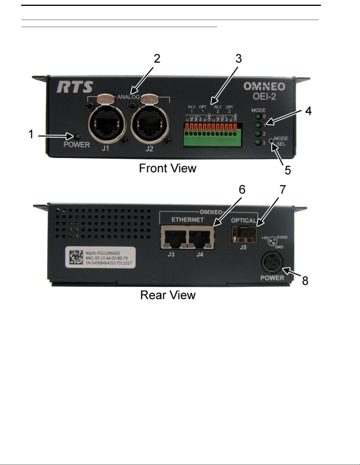
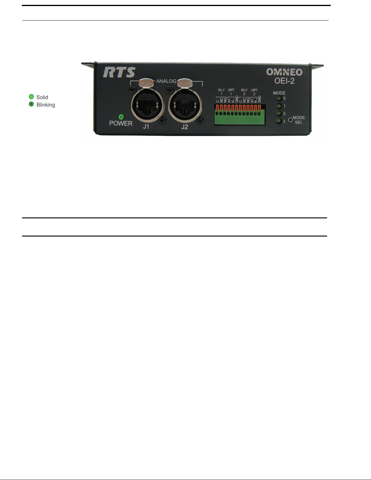
Reference View
FIGURE 1. OEI-2 Reference View
1. Power Light Indicator
2. Channel 1 and Channel 2 – Ethercon RJ-45 Connectors
3. Relay and Opto Isolate Terminal Block
4. Mode Indicator Lights
5. Mode Selection Switch
6. Ethernet Connectors
7. Fiber Connector
8. Power Connector
Bosch Security Systems, Inc.
Technical Manual
F.01U.287.527
Rev. 01
Page 9

OEI-2 Introduction 9
Specifications
General
Dimensions..................................................................................................5.80in x 1.93in x 4.45in (147mm x 49mm x 113mm)
Weight ......................................................................................................................................................................23.2 oz (658g)
Power
Requirements.........................................................................................................................................................5VDC, 2000mA
Power Consumption @ 120VAC ...........................................................................................................................................21VA
Power Consumption @ 220VAC ...........................................................................................................................................27VA
Connectors
2– RJ-45 Ethernet Connectors
SFP Fiber Connector.........................................................................................................................................................LC Type
GP Inputs 1–2
Type.................................................................................................................................................................... Optically coupled
Input ...........................................................................................................................................Internal pull-up resistor to 5VDC
.............................................................................................................................External power up 5–18VDC
GP Outputs 1–2
Type...............................................................................................relays with common normal open and normal closed contacts
Contact Ratings ...............................................................................................................................................1.0 Amp @ 30VDC
Data Keypanel......................................................................................................................................................................RS485
Analog
Input
Type.....................................................................................................................................................................Balanced floating
Level Nominal........................................................................................................................................................................ 8dBu
Level Maximum ................................................................................................................................................................... 20dBu
Impedance ..............................................................................................................................................................................10k
Output
Type.....................................................................................................................................................................Balanced floating
Level Nominal........................................................................................................................................................................ 8dBu
Level Maximum ................................................................................................................................................................... 20dBu
Impedance ..............................................................................................................................................................................600
THD+Noise....................................................................................................<0.1% (measured at 20-20kHz, +0 dBu, unity gain
Digital
Audio
Frequency Response..................................................................................................................................20Hz to 20kHz; ±0.1dB
System Gain ............................................................................................................................................................................ 0 dB
Bandwidth
48kHz/24-bit per channel...............................................................................................................................................2.59Mbit/s
Analog to OMI latency........................................................................................................................................................... 20ms
OMI to Analog latency........................................................................................................................................................... 20ms
Environmental
Storage Temperature ...................................................................................................................... -4°F to 158°F (-20°C to 70°C)
Operating Temperature......................................................................................................................32°F to 131°F (0°C to 55°C)
Bosch Security Systems, Inc.
Technical Manual
F.01U.287.527
Rev. 01
Page 10

10 Introduction OEI-2
Connectors
RJ-45 Pinout
TABLE 1. RJ-45 Analog Connector Pin Out
Pin Description
KP Mode Audio Mode
1RS485 Data + NA
2RS485 Data - NA
3 Audio Out + Audio In+
4 Audio In + Audio Out+
5 Audio In - Audio Out -
6 Audio Out - Audio In -
7RS485 Data + NA
8RS485 Data - NA
IMPORTANT: Keypanels support RTS protocol, USOC, and 568B CAT-5e wiring scheme for RS485 data.
Ter m in al B loc k
RLY 1 C
NC
NO
OPT 1
RLY 2 C
OPT 2 A+
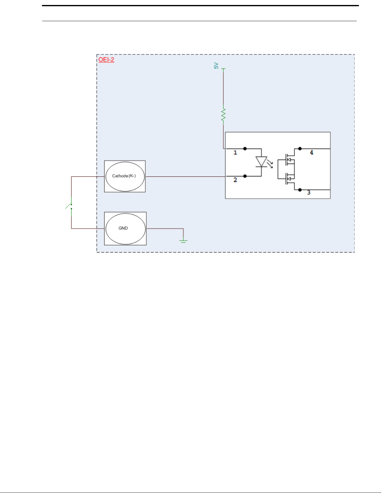
a. Anode
b. Cathode
a
A+
b
K-
GND
NC
NO
K-
GND
Bosch Security Systems, Inc.
Technical Manual
F.01U.287.527
Rev. 01
Page 11
OEI-2 Introduction 11
FIGURE 2. GPIO Input Diagram
Bosch Security Systems, Inc.
Technical Manual
F.01U.287.527
Rev. 01
Page 12
12 Introduction OEI-2
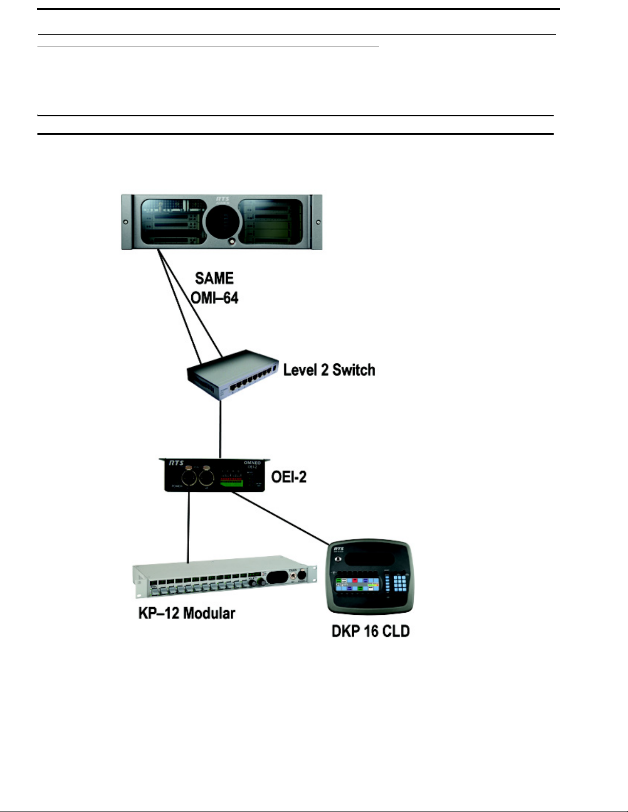
System Drawings
Same Frame, Same OMI Card
IMPORTANT: An OMI Card is necessary for operation.
FIGURE 3. Same Frame, Same OMI Card System
Bosch Security Systems, Inc.
Technical Manual
F.01U.287.527
Rev. 01
Page 13

OEI-2 Introduction 13
Same Frame, Different OMI Cards
IMPORTANT: An OMI Card is necessary for operation.
FIGURE 4. Same Frame, Different OMI Cards System
IMPORTANT: ARNI is only required, if access beyond each subnet is desired by the OMI cards.
Bosch Security Systems, Inc.
Technical Manual
F.01U.287.527
Rev. 01
Page 14

14 Introduction OEI-2
Different Frames, Different OMI Cards
IMPORTANT: An OMI Card is necessary for operation.
FIGURE 5. Different Frames and Different OMI Cards System
IMPORTANT: ARNI is only required, if access beyond each subnet is desired by the OMI cards.
Bosch Security Systems, Inc.
Technical Manual
F.01U.287.527
Rev. 01
Page 15

OEI-2 Introduction 15
Audio Only
FIGURE 6. Audio Only System
IMPORTANT: ARNI is only required, if access beyond each subnet is desired by the OMI cards.
Bosch Security Systems, Inc.
Technical Manual
F.01U.287.527
Rev. 01
Page 16

16 Introduction OEI-2
Bosch Security Systems, Inc.
Technical Manual
F.01U.287.527
Rev. 01
Page 17

System Requirements
You must have the following:
• OEI-2 version 1.1.4 or later
• OMI version 5.1.3 or later
• OKI version 5.1.3 or later
• IPedit version 3.1.0 or later
OR
AZedit version 4.7.0 or later
• FWUT version 3.0.3 or later
CHAPTER 2
Installation
Bosch Security Systems, Inc.
Technical Manual
F.01U.287.527
Rev. 01
Page 18

18 Installation OEI-2
Installation Instructions
Mounting the Unit
To mount the OEI-2 to the underside of a desk, do the following:
1. Holding the OEI-2 unit in the spot you want to mount it, make guide marks, using a marker, for the screw placement.
TIP: To make attaching the unit easier, pre-drilling the screw holes is suggested.
2. Using a screwdriver, attach the OEI-2 unit to the predefined mounting area with the four (4) screws supplied.
Cabling
To install the OEI-2, do the following:
1. On the rear of the OEI-2 unit, connect either the Ethernet (J3 or J4) or Optical connector (J5) to a switch or
OMNEO device connected to the Matrix.
Bosch Security Systems, Inc.
Technical Manual
F.01U.287.527
Rev. 01
Page 19
OEI-2 Installation 19
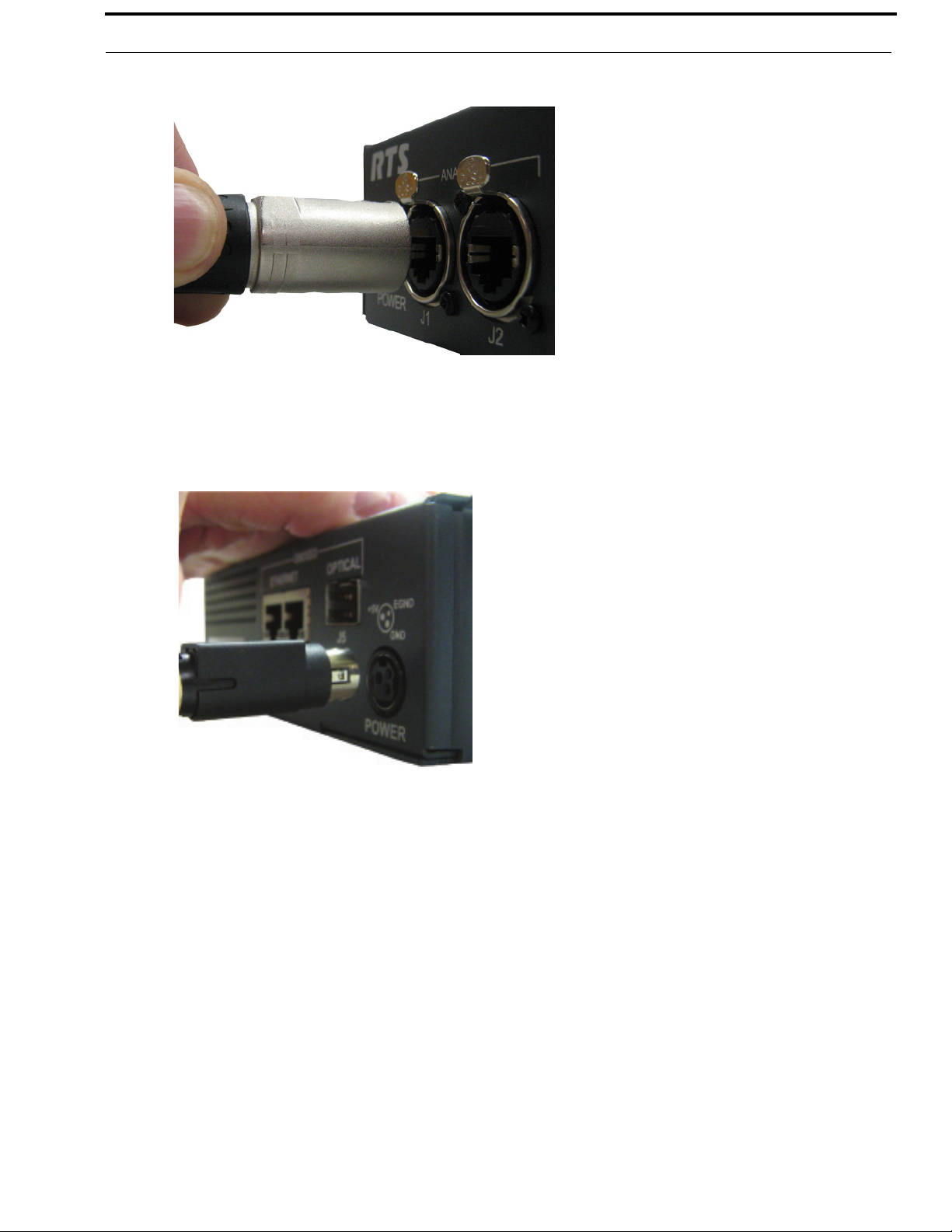
2. On the front of the OEI-2 unit, connect J1 or J2 to the Frame connector on the keypanel.
3. Connect one end of the power supply to the OEI-2 and the other end to the wall outlet.
The OEI-2 powers on. On initial power up, only the Power LED is seen.
NOTE: If you need to mount the power supply (P/N RP_OEI_PS_BRK), see “Optional Power Supply Mount” on
page 37.
4. Using IPedit or AZedit, configure the OMI with the OEI-2. See “Configure an OEI-2 Using AZedit” on page 21 or
“Configure an OEI-2 Using IPedit” on page 23.
Bosch Security Systems, Inc.
Technical Manual
F.01U.287.527
Rev. 01
Page 20

20 Installation OEI-2
Bosch Security Systems, Inc.
Technical Manual
F.01U.287.527
Rev. 01
Page 21

CHAPTER 3
Configuration
OEI-2 Power Cycle
The OEI-2 has an external switch primarily used to power cycle the unit without disrupting power to the unit. For more
information, see “Power On Reset” on page 36.
To power cycle the OEI-2 unit, do the following:
1. Using a straightened paperclip, press and hold the MODE SEL button for 10 seconds.
The POWER and MODE LEDs start blinking.
1. Remove the straightened paperclip from the MODE SEL button.
The POWER LED turns off. The OEI-2 is power cycled.
Software Configuration
Configure an OEI-2 Using AZedit
To configure an OEI-2 with an OMI card using AZedit, do the following:
1. Start AZedit.
2. From the Status menu, select I/O Cards.
The I/O Card Status window appears displaying a list of recognized cards.
3. Right-click an OMI card.
A pop-up menu appears.
Bosch Security Systems, Inc.
Technical Manual
F.01U.287.527
Rev. 01
Page 22
22 Configuration OEI-2
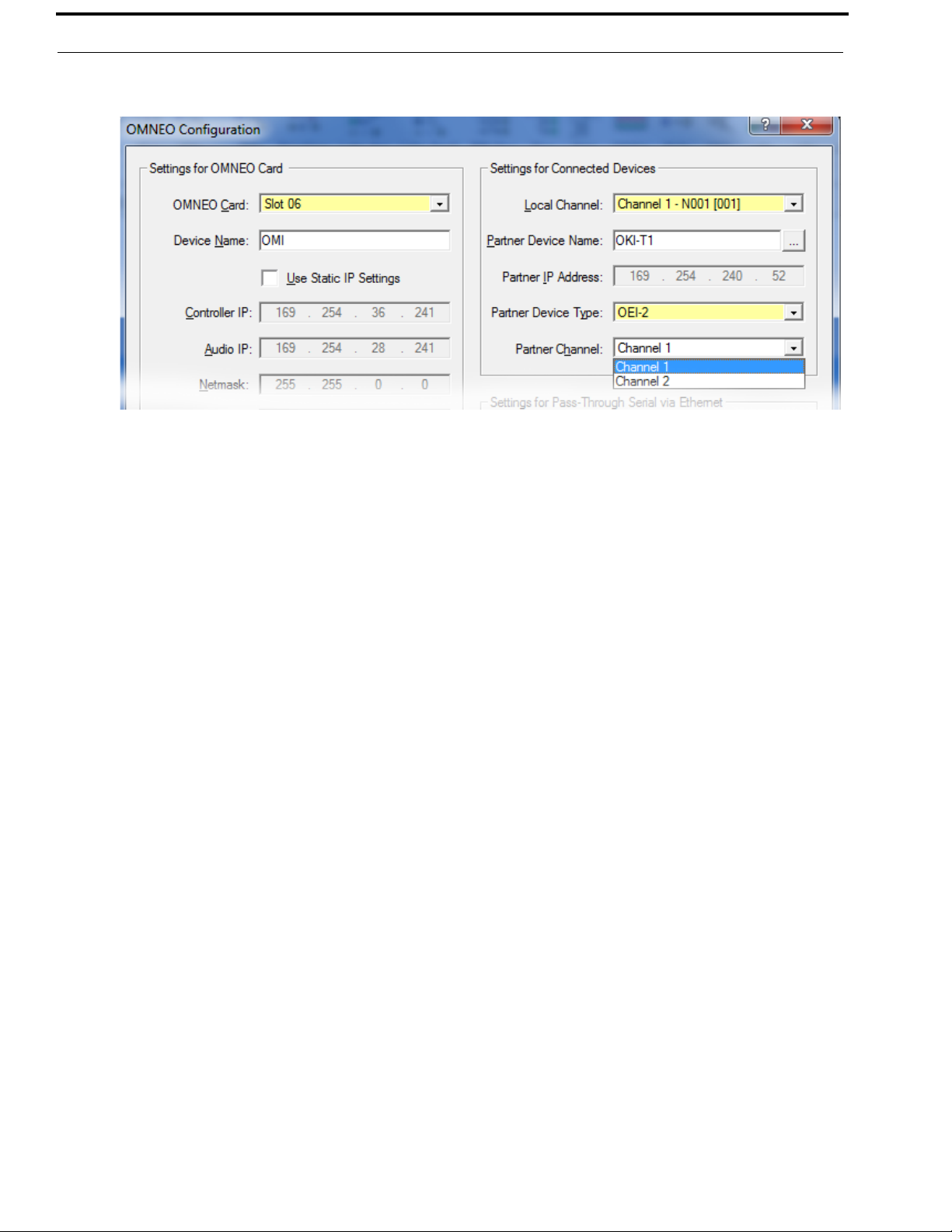
4. From the pop-up menu, select OMNEO Configuration.
The OMNEO Configuration window appears.
5. Verify the Settings for OMNEO Card information is correct.
6. From the Local Channel drop down list, select the channel you want to use to communicate from the OMI to the
OEI-2 device.
NOTE: Non-allocated channels appear with an asterisk next to them.
7. Select the Browse icon to open the Discovered Devices window from which you can choose the device.
The Partner IP Address field automatically populates.
OR
In the Partner Device Name field, enter the name of the OEI-2 you want to communicate with.
8. From the Partner Device Type drop down menu, select OEI-2.
NOTE: If the system detects the type of device it is, the Partner Device Type automatically populates.
9. From the Partner Channel drop down menu, select the channel on the OEI-2 to which the OMI communicates.
10. Click Apply.
Bosch Security Systems, Inc.
Technical Manual
F.01U.287.527
Rev. 01
Page 23
OEI-2 Configuration 23
Configure an OEI-2 Using IPedit
To configure an OEI-2 with an OMI card using IPedit, do the following:
IMPORTANT: You must be signed on with network administrator rights to complete these instructions.
1. Start IPedit.
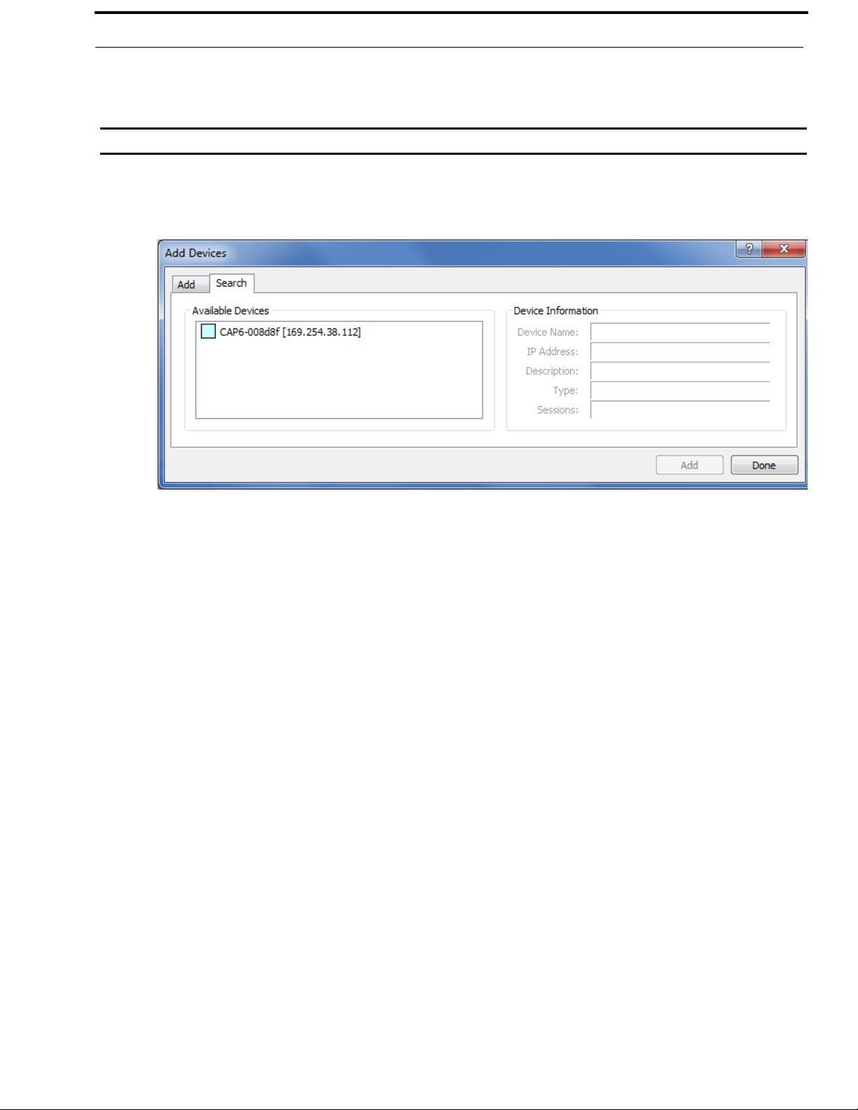
2. From the Device menu, select Add.
The Add Devices window appears.
3. From the Available Devices pane, select the OEI-2 device.
The Add button becomes active.
4. Click Add.
The OEI-2 appears in the device catalog in the left panel.
5. Click Done.
The Add Devices window closes.
Bosch Security Systems, Inc.
Technical Manual
F.01U.287.527
Rev. 01
Page 24
24 Configuration OEI-2
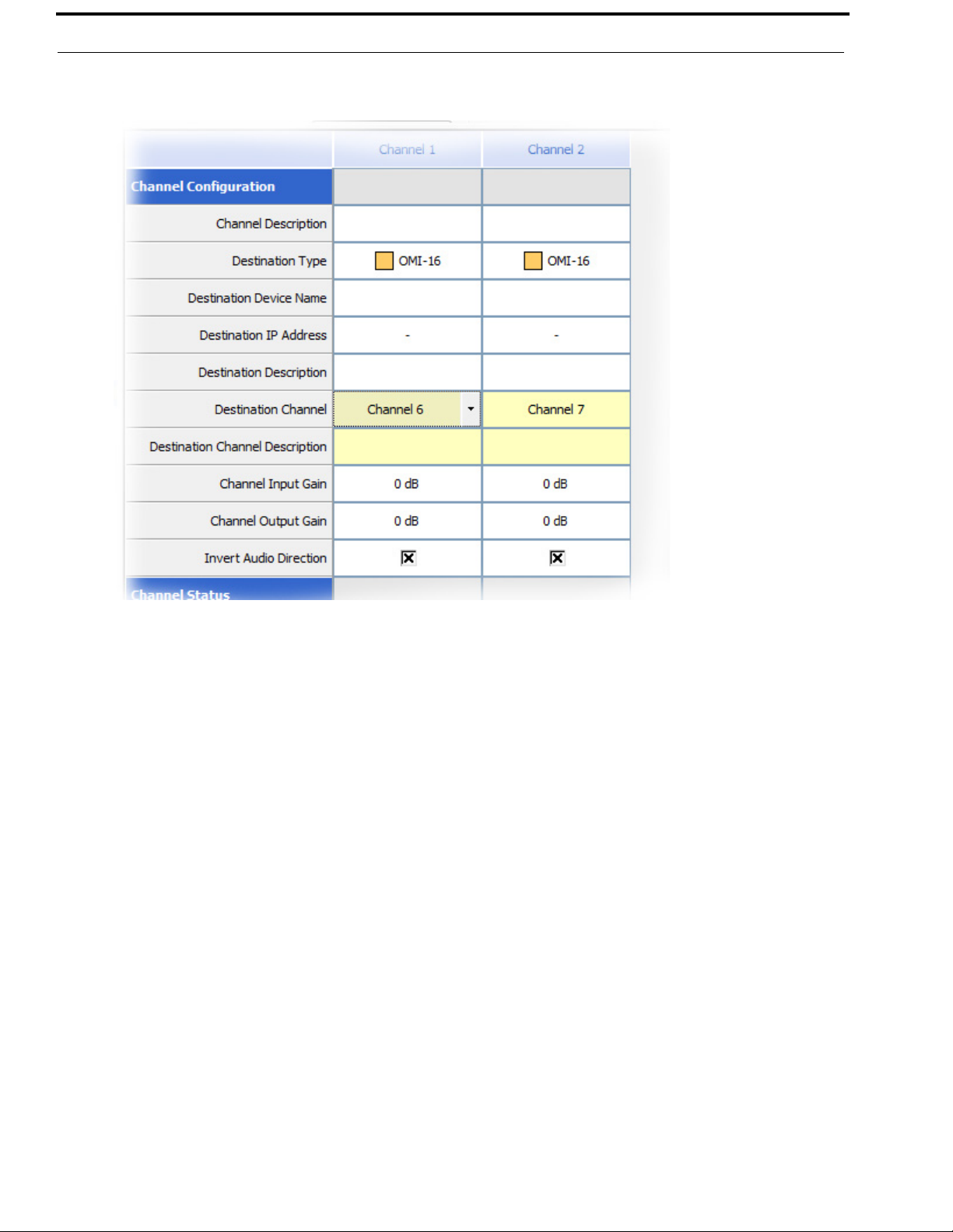
6. From the Device Catalog on the left, select the OEI-2 device.
The Channel Configuration and Status Section populates.
7. From the column headings, select the channel you want to configure (for example, Channel 1 or Channel 2).
8. In the Channel Description field, enter a channel description, if applicable.
9. From the Destination Type drop down menu, select the OMI card to which the channel is connected.
10. In the Destination Device Name field, enter the name of the OMI card to which the channel is connected.
OR
Click the browse button.
The Discovered Devices window appears.
a. Expand the local. tree to view the destination devices available.
b. From the expanded tree, select the device you want for you destination device.
c. Click OK.
The Discovered Devices window closes.
11. From the Destination Channel drop down menu, select the destination channel to which the channel is connected.
12. From the File menu, click Save.
Bosch Security Systems, Inc.
Technical Manual
F.01U.287.527
Rev. 01
Page 25
OEI-2 Configuration 25
Firmware Upload – OEI-2
To upload firmware to the OEI-2 unit, do the following:
1. Start IPedit.
NOTE: The OEI-2 unit must be configured before you upgrade the firmware. For more information, see “Configure
an OEI-2 Using IPedit” on page 23.
2. Select the OEI-2 device you want to update.
3. Right-click the OEI-2 device you want to update.
A popup menu appears.
4. From the popup menu, select Download Firmware.
The OMNEO Firmware Upload Tool starts.
5. From the Network adapter drop down menu, select the network adapter you are using.
6. Click OK.
The OMNEO Firmware Upload Tool window appears.
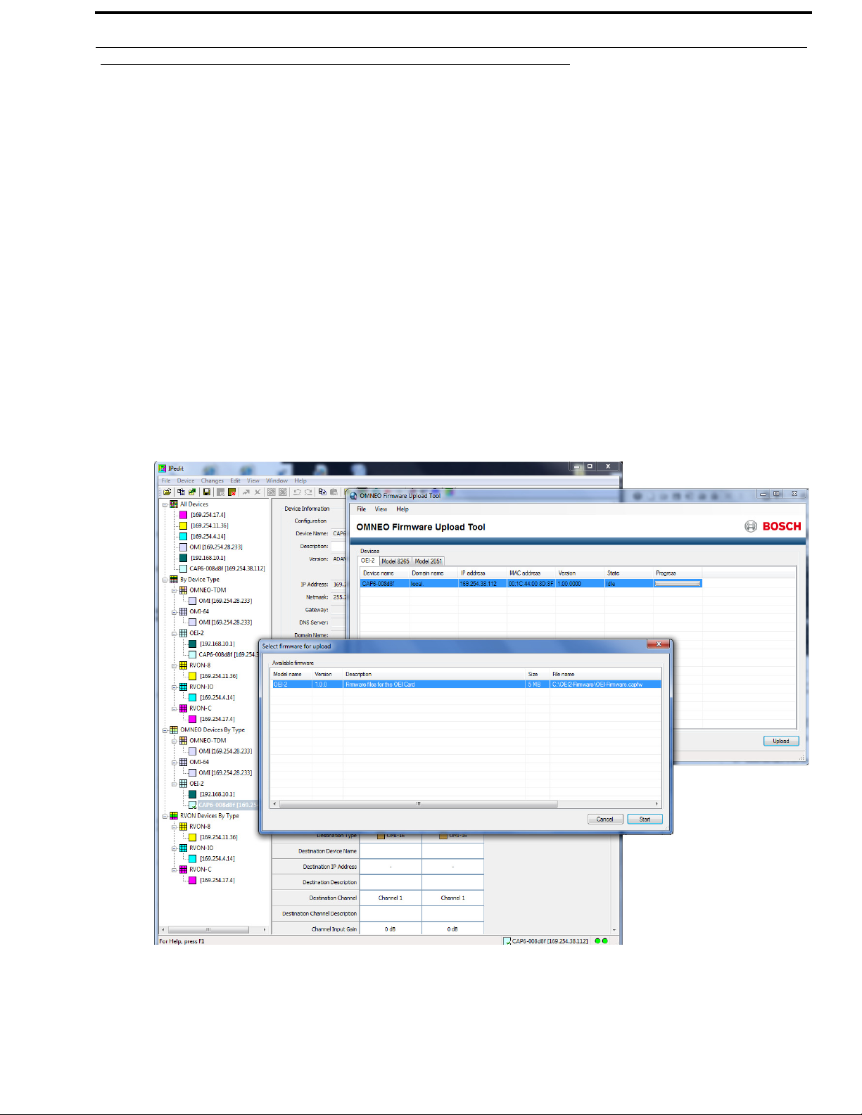
7. Click the OEI-2 tab.
The OEI-2 page appears.
8. Select the OEI-2 device.
9. Click Upload.
The Select firmware for upload window appears.
10. Select the OEI-2 Firmware.
The Start button becomes active.
11. Click Start.
The firmware begins to upload to the OEI-2 device.
Bosch Security Systems, Inc.
Technical Manual
F.01U.287.527
Rev. 01
Page 26

26 Configuration OEI-2
LED Indicators
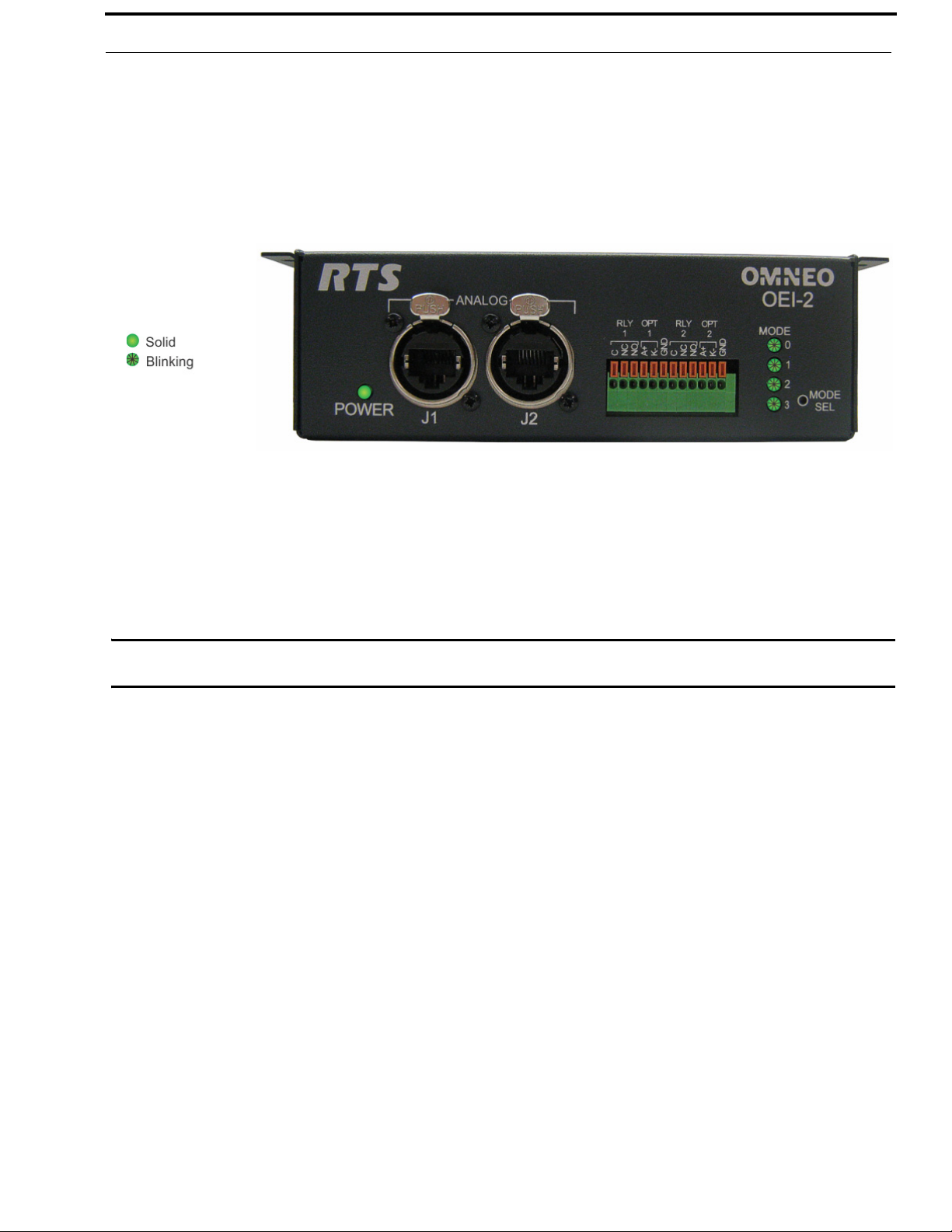
Power Indicator LED
The Power Indicator LED, located on the lower left corner of the OEI-2 front panel, indicates if power is being supplied to
the unit or if there is a communication failure between the OEI-2 and the OMI.
When power is supplied to the unit, the power indicator LED is a constant green.
FIGURE 7. Powered OEI-2 Unit
NORMAL Operation
In Normal operation mode the OEI-2 unit displays LED indication for channel 1 and channel 2.
The channel indicator LEDs are as follows:
Channel 1 is represented by the LED 0
Channel 2 is represented by the LED 1
When blinking is seen on LED 0 or LED 1, this indicates the keypanels are connected and are configured.
FIGURE 8. Keypanels Connected and Configured
Bosch Security Systems, Inc.
Technical Manual
F.01U.287.527
Rev. 01
Page 27

OEI-2 Configuration 27
If a keypanel is connected to the OEI-2 unit, but is not configured, the LED is off.
FIGURE 9. Two (2) Keypanels Connected and One (1) Keypanel Not Configured
FAULT Indicator
When there is a communication failure, or a FAULT the power indicator starts blinking.
FIGURE 10. FAULT Indicator
Bosch Security Systems, Inc.
Technical Manual
F.01U.287.527
Rev. 01
Page 28

28 Configuration OEI-2
User Modes
User Mode Selection
User Modes are used to define how the OEI-2 handles different requests, such as changing the IP Address of the OEI-2 unit,
changing the direction of the audio, configuring GPIO Modes, and reset configuration options. The User Modes are as
follows:
Mode 0 – IP Change Mode
Mode 1 – Audio Direction
Mode 2 – Set GPIO Mode
Mode 3 – Select Port GPIO
RTS IPedit Configuration Software must be used to configure the modes. Three (3) of the modes can be configured from the
front panel of the OEI-2; IP Change Mode, Reset Configuration, and Power On Reset.
Mode 0 - IP Change Mode
IP Change Mode allows the user to change the IP address of the unit through the use of a keypanel connected to port 1 on the
OEI-2 unit (see Figure 1, “OEI-2 Reference View,” on page 8).
NOTE: Once the mode is selected, any power cycles performed will not reset this selection to default.
By default, the IP Change Mode is disabled. However, it can be toggled on and off using the MODE SEL button, located in the
lower-left corner on the front panel of the OEI-2 unit. The IP Change Mode also can be enabled and disabled through the
IPedit interface software.
To enable IP Change Mode from the OEI-2 unit, do the following:
1. Using a straightened paper clip, press the MODE SEL button once.
IP Mode changes.
2. Continue pressing the MODE SEL button to cycle through the different modes.
IMPORTANT: To indicate the IP Change Mode is enabled, the MODE 3 LED flashes for five (5) seconds, and then it
resumes its previous activity.
IMPORTANT: For instructions on changing the IP Address of the OEI-2 device from the Keypanel, refer to the specific
keypanel manual.
IMPORTANT: Only OMNEO menu enabled devices can modify the IP Address of an OEI-2 device.
Bosch Security Systems, Inc.
Technical Manual
F.01U.287.527
Rev. 01
Page 29

OEI-2 Configuration 29
To enable IP Change Mode from IPedit, do the following:
1. Start IPedit.
2. From the left navigation, select the OEI-2 device you want to configure.
The Device Information panel populates.
3. Select the Enable IP Configuration via KP check box.
Bosch Security Systems, Inc.
Technical Manual
F.01U.287.527
Rev. 01
Page 30

30 Configuration OEI-2
IMPORTANT: For instructions on changing the IP Address of the OEI-2 device from a specific keypanel, refer to the
appropriate keypanel manual.
Change the IP Address of the OEI-2 device from an RP-1000
NOTE: Only OMNEO menu enabled devices can modify the IP Address of an OEI-2 device.
To select the fixed addressing for the OMNEO device, do the following:
1. Using the arrow keys, select OMNEO Setup.
2. Tap PGM.
Device Name appears.
3. Using the arrow keys, scroll to DHCP
4. Tap PGM.
Disabled and Enabled appear in the display.
5. Using the arrow keys, select Fixed IP.
6. Tap PGM.
The addressing type is set.
To configure the IP Parameters for the OMNEO device, do the following:
1. Using the arrow keys, select OMNEO Setup.
2. Tap PGM.
Device Name, DHCP, and IP Parameters appear in the display.
3. Using the arrow keys, scroll to IP Parameters.
4. Tap PGM.
IP Address appears in the keypanel display.
5. Tap PGM.
The IP Address octet appears in the keypanel display with the first octet blinking.
6. Using the keypad, enter the IP Address.
Use the PGM key as the dots between octets.
7. When finished entering the IP Address, tap PGM.
Netmask appears in the keypanel display.
8. Tap PGM.
The Netmask octet appears in the keypanel display with the first octet blinking.
9. Using the keypad, enter the Netmask, if necessary.
Use the PGM key as the dots between octets.
10. When finished entering the Netmask, tap PGM.
Gateway appears in the keypanel display.
11. Using the keypad, enter the Gateway, if necessary.
Use the PGM key as the dots between octets.
12. When finished entering the Gateway, tap PGM.
The DNS Srv 1 appears in the keypanel display.
13. Using the keypad, enter the DNS Svr 1 address, if necessary.
Use the PGM key as the dots between octets.
14. When finished entering the DNS Svr 1 address, tap PGM.
Domain appears in the keypanel display.
15. Tap PGM.
The Domain name appears in the keypanel display with the first character blinking.
16. Using the arrows, scroll to the to the first character of the device name desired.
Bosch Security Systems, Inc.
Technical Manual
F.01U.287.527
Rev. 01
Page 31

OEI-2 Configuration 31
17. Tap PGM.
The focus moves to the next character in the device name.
NOTE: You can also use the volume control to move the cursor position to the left and right.
18. Repeat steps 19 and 20 until the Domain Name is entered.
CLR deletes the current character. 0 can be used to insert a character at the current position. Scroll up/scroll down
can also be used to move the current cursor position.
19. Tap FWD to exit.
20. Select Save Cfg to store the OMNEO Setup settings.
Mode 1 - Audio Direction Selection
Audio Direction Selection mode allows the user to change the direction of the audio on the OEI-2. This means the audio
output port can be changed to become the audio input port for their respective ports. This allows the user to connect audio
channels directly to an AIO-16 breakout panel or to the Zeus III ports.
By default, the OEI-2 channels receive audio from the matrix. However, you can modify the configuration to send audio
to the matrix. This is done using the IPedit software application.
FIGURE 11. Audio Direction Mode
Mode 1a - Audio on CH1 and Audio+Data on CH2
FIGURE 12. Audio Direction Mode – Channel 1
Bosch Security Systems, Inc.
Technical Manual
F.01U.287.527
Rev. 01
Page 32
32 Configuration OEI-2
Mode 1b - Audio+Data on CH1 and Audio on CH2
FIGURE 13. Audio Direction Mode – Channel 2
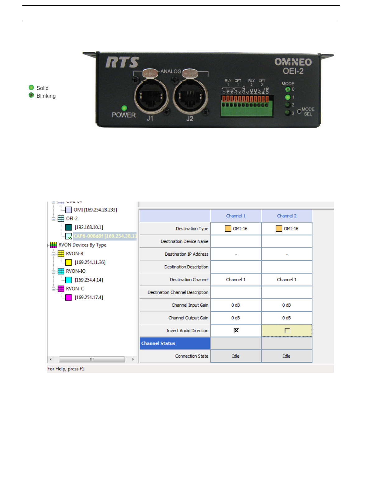
Change the Channel Audio Direction via IPedit
To change the channel audio direction using IPedit, do the following:
1. Start IPedit.
2. From the left navigation pane, select the OEI-2 device you want to modify.
The Device Information and Channel Status information populates.
3. From the Channel Status, Invert Audio Direction Row, select the Channel check box you want to modify (either
channel 1 or channel 2).
Bosch Security Systems, Inc.
Technical Manual
F.01U.287.527
Rev. 01
Page 33

OEI-2 Configuration 33
Mode 2 - Set GPIO Mode
NOTE: The Set GPIO Mode can only be configured using IPedit or from the front panel.
Set GPIO Mode allows the user to select between two (2) modes:
FIGURE 14. Single Keypanel – Channel 1 (LED 2 is solid)
1 Keypanel Mode (single-port mode) – All GPI/Os are controlled by one (1) port. Associating the GPI/O with one port
allows you to access/address the GPI/O in UPL Statements. Mode 3 is used to
define the port to used. The GPI/O is associated with J1. This means that Port 0
has eight GPI/O’s mapped to it. Connected to J1 is a keypanel with the keypanel
ID of 33 in AZedit.
To use the GPI/O, you can create UPL statements. But be careful to assign the
correct Output Action parameters:
RLY1 and OPT1 are Local GPIO 9 on the same keypanel
RLY2 and OPT2 are Local GPIO 10 on the same keypanel
FIGURE 15. Single Keypanel – Channel 2 (LED 3 is solid)
All Keypanel Mode (multi-port mode) – Each port is associated with its corresponding GPI/O. This means if keypanel 1
is connected to GPI/O 1, it is associated with the corresponding GPI/O port.
GPIO1 and RLY1 are paired and assigned to the same panel. These cannot be
split across devices.
Bosch Security Systems, Inc.
When using this mode, an additional GPI/O is available on each port.
RLY1 and OPT1 are represented in AZedit by Local GPIO 9 on the keypanel
connected to J1
RLY2 and OPT2 are represented in AZedit by Local GPIO 9 on the keypanel
connected to J2
Technical Manual
F.01U.287.527
Rev. 01
Page 34
34 Configuration OEI-2
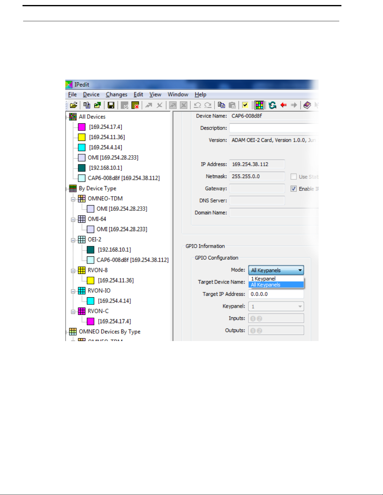
To configure the GPIO mode, do the following:
1. Open IPedit.
2. From the left navigation, select the OEI-2 unit you want to configure.
The Device Information Pane populates.
3. From the Mode drop down menu, select All Keypanels or 1 Keypanel.
Bosch Security Systems, Inc.
Technical Manual
F.01U.287.527
Rev. 01
Page 35
OEI-2 Configuration 35
Mode 3 - Select Port for GPI
Select Port for GPIO Mode is used in conjunction with Mode 2. When 1 Keypanel Mode is selected, the user can select the
port the GPI/Os are assigned.
Reset Configuration
Reset Configuration Mode allows the user to reset all modes to the factory defaults. This also turns all the LEDs off.
FIGURE 16. Reset Configuration
To reset the configuration from the front panel of the OEI-2, do the following:
1. Using a straightened paperclip, press and hold the MODE SEL button for six (6) seconds.
All four (4) MODE LEDs start blinking.
2. Remove the straightened paperclip from the MODE SEL button.
The LEDs turn off. The OEI-2 is reset to Factory default.
IMPORTANT: If the MODE SEL button is held past eight (8) seconds the MODE LEDs stop flashing and show the
existing MODE settings. This means the reset configuration did not occur.
Bosch Security Systems, Inc.
Technical Manual
F.01U.287.527
Rev. 01
Page 36
36 Configuration OEI-2
Power On Reset
The Power On Reset Mode allows the user to cycle power to the OEI-2 unit.
FIGURE 17. Power On Reset
To configure the Power On Reset mode from the front panel of the OEI-2, do the following:
1. Using a straightened paperclip, press and hold the MODE SEL button for 10 seconds.
The POWER and MODE LEDs start blinking.
2. Remove the straightened paperclip from the MODE SEL button.
The POWER LED turns off. The OEI-2 is configured for POWER ON Reset Mode.
IMPORTANT: If the MODE SEL button is held past 15 seconds the MODE LEDs stop flashing and show the existing
MODE settings. This means the reset configuration did not occur.
Bosch Security Systems, Inc.
Technical Manual
F.01U.287.527
Rev. 01
Page 37
APPENDIX A
Optional Power Supply Mount
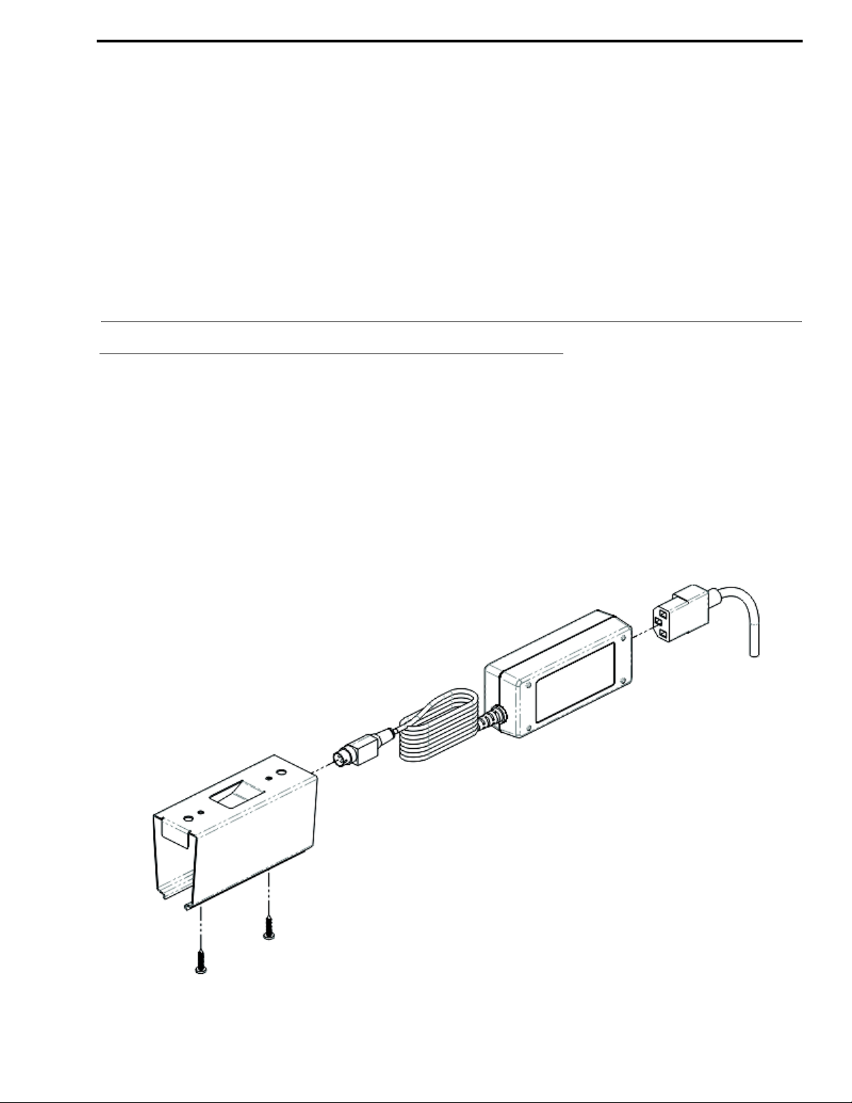
Power Supply Rackmount Assembly Instructions
An optional power supply rackmount is available for purchase (P/N RP_OEI_PS_BRK), if needed.
To mount the power supply rackmount assembly, do the following:
1. Holding the rackmount assembly unit in the spot you want to mount it, make guide marks, using a marker, for the
screw placement.
TIP: To make attaching the unit easier, pre-drilling the screw holes is suggested.
2. Using a screwdriver, attach the rackmount assembly unit to the predefined mounting area with the two (2) screws
supplied.
FIGURE 18. Power Supply Mounting Assembly
3. Carefully slide the power supply into the rackmount unit, as shown in Figure 18.
Bosch Security Systems, Inc.
Technical Manual
F.01U.287.527
Rev. 01
Page 38
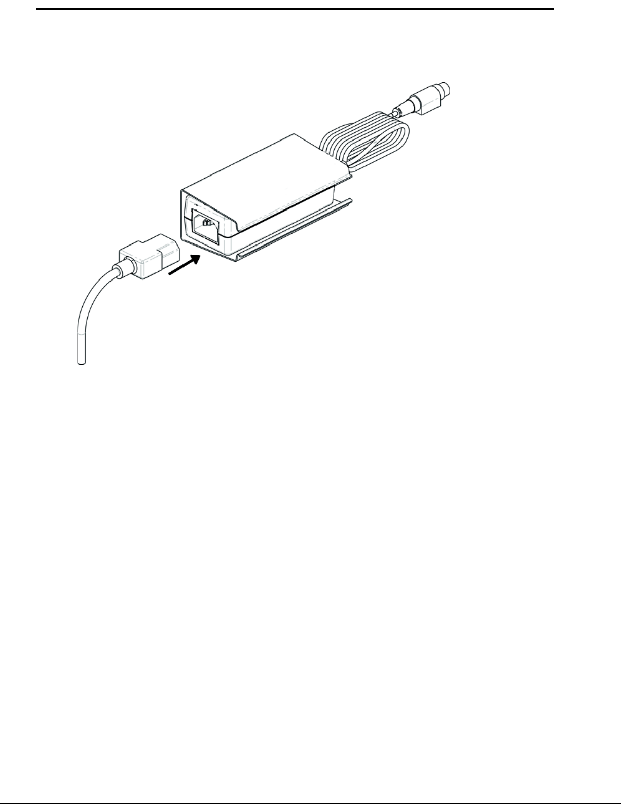
38 OEI-2
4. Attach the power cord to the power supply unit.
FIGURE 19. Attach Power Cord to Power Supply Unit
5. Attach the other end of the power cord to the power outlet.
Bosch Security Systems, Inc.
Technical Manual
F.01U.287.527
Rev. 01
Page 39

OEI-2 39
NOTES
Bosch Security Systems, Inc.
Technical Manual
F.01U.287.527
Rev. 01
Page 40

Bosch Security Systems, Inc.
12000 Portland Avenue South
Burnsville, MN 55337 U.S.A.
www.boschcommunications.com
 Loading...