

Page 1
MCII-e
System Contr oller Car d
User Manual
9350-7734-000 Rev B April / 2007
Page 2

PROPRIETARY NOTICE
SHIPPING TO THE MANUFACTURER
The product information and design disclosed herein were originated by
and are the property of Telex Communications, Inc. Telex reserves all
patent, proprietary design, manufacturing, reproduction, use and sales
rights thereto, and to any article disclosed therein, except to the extent
rights are expressly granted to others.
COPYRIGHT NOTICE
Copyright 2006 by Telex Communications, Inc. All rights reserved.
Reproduction, in whole or in part, without prior written permission from
Telex is prohibited.
WARRANTY NOTICE
See the enclosed warranty card for further details.
CUSTOMER SUPPORT
Te chnical questions should be directed to:
Customer Service Department
RTS/Telex Communications, Inc.
12000 Portland Avenue South
Burnsville, MN 55337 USA
Telephone: 800-392-3497
Fax: 800-323-0498
RETURN SHIPPING INSTRUCTIONS
Customer Service Department
Telex Communications, Inc. (Lincoln, NE)
Telephone: 402-467-5321
Fax: 402-467-3279
Factory Service: 800-553-5992
Please include a note in the box which supplies the company name,
address, phone number, a person to contact regarding the repair , the type
and quantity of equipment, a description of the problem and the serial
number(s).
All shipments of product should be made via UPS Ground, prepaid (you
may request from Factory Service a different shipment method). Any
shipment upgrades will be paid by the customer. The equipment should
be shipped in the original packing carton. If the original carton is not
available, use any suitable container that is rigid and of adequate size. If
a substitute container is used, the equipment should be wrapped in paper
and surrounded with at least four (4) inches of excelsior or similar
shock-absorbing material. All shipments must be sent to the following
address and must include the Proof of Purchase for warranty repair.
Upon completion of any repair the equipment will be returned via
United Parcel Service or specified shipper, collect.
Factory Service Department
Telex Communications, Inc.
8601 East Cornhusker Hwy.
Lincoln, NE 68507 U.S.A.
Attn: Service
This package should include the following:
This package should include the following:
Component Description Qty.
90207734000 MCII-e Front Card Assembly 1
90207734500 MCII-e Back Card Assembly 1
59000240 Screw, M2.5-45x10 PH Pan Head M/S DIN
7985A Zinc
93507734000 Master Controller User Manual 1
38110387 RTS Warranty Lincoln 3 year 1
90207562010 Cable, SCSI-III 10 Ft. Amp 750732-4 1
4
Page 3

Table
of
Contents
Introduction .........................................................3
Introduction .........................................................4
Features ................................................................4
Specifications ......................................................4
System Diagram ..................................................5
Reference View - Front Card ..............................6
Reference View - Back Card ...............................8
DIP Switches .......................................................8
Connector Pinouts .............................................10
Configuring the MCII-e .....................................13
System Requirements ........................................14
Ethernet Setup for MCII-e
System Controller ..............................................14
Set the IP Address for the
MCII-e System Controller .................................14
Download Firmware for the
MCII-e System Controller .................................16
Accessories ........................................................ 19
Accessories ........................................................ 20
XCP-ADAM-MC Master Controller
Breakout Panel ...................................................20
AZedit ................................................................ 20
Trunking Systems ..............................................20
UIO-256 .............................................................20
PAP .................................................................... 21
LCP .................................................................... 21
GPI/O (General Purpose Input/Output) .............21
Trunking and the MCII-e System ......................23
Trunking and the MCII-e System Controller ....24
Page 4

Page 5

In this chapter
CHAPTER 1
Intr oduction
• Introduction
• Features
• Specifications
• Reference View - Front Card
• Reference View - Back Card
• DIP Switches
• Connector Pin-out s
3
Page 6

Introduction
Introduction
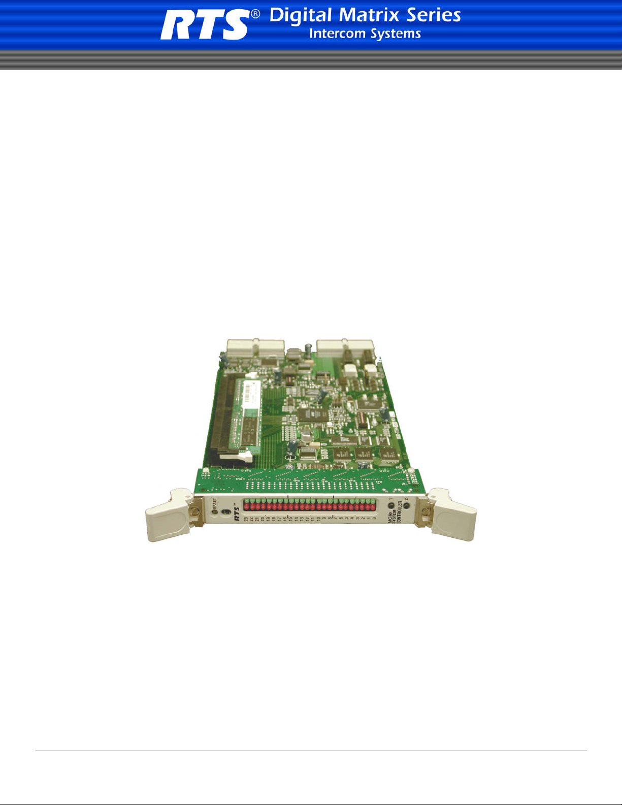
The RTS MCII-e System controller card is the third generation controller for the ADAM Intercom System. Designed to
replace the ADAM-MC, it adds a number of key features. Adding Ethernet connectivity between the ADAM Intercom and the
PC running AZedit, the new controller can support up to 35 simultaneous AZedit sessions (32 using Ethernet and up to 3 using
serial ports). Using a pair of MCII-e controller cards will provide full redundancy with seamless automatic change-over upon
failure.
The speed of Ethernet, combined with expanded memory, allows the card to fully support large matrices with reduced setup
file download time.
As with all ADAM™ Intercom family products, the MCII-e card supports all standard, hot-swappable, and configurable
features through the AZedit configuration software. It is fully compatible with existing ADAM systems and cards, including
AIO-8, AIO-16, AES-3, and RVON VOIP interfaces
*The New MCII-e System Controller card is only for use in the ADAM Matrix Intercom System and cannot be intermixed with older ADAM
master controllers in a given frame.
Features
Installation: The MCII-e System Controller card is hot-swappable and installs into slots 19 or 20 in an
ADAM™ Intercom System.
®
Trunk Capable: The MCII-e System Controller card supports ancillary data control for use with Telex
Trunking.
Ethernet Compatible: Fully Ethernet capable. The MCII-e provides a single RJ-45 connection for use with a 10BASE-T
or 100BASE-TX compliant and network. Each system contro ller ha s its own IP address network
access.
AZedit Configurations: The MCII-e can connect to AZedit via Ethernet or Serial (RS-232) connections. Also, the new
Intercom Sizing Wizard in AZedit makes configuring the new system controller card easier than
ever.
Controls: Reset push-button switch, general indicators, an LED module for advanced monitoring features and
for gathering additional card information.
Intelligent
Specifications
Power
7.5W/ 1.5A @ 5V
Physical
5.687” (144.45mm) W x 11.024” (280.01 mm) L
Connectors
SCSI connector via backcard
RJ-45 Ethernet via backcard
Miscellaneous
4 Mbytes of Code Flash
4
Page 7
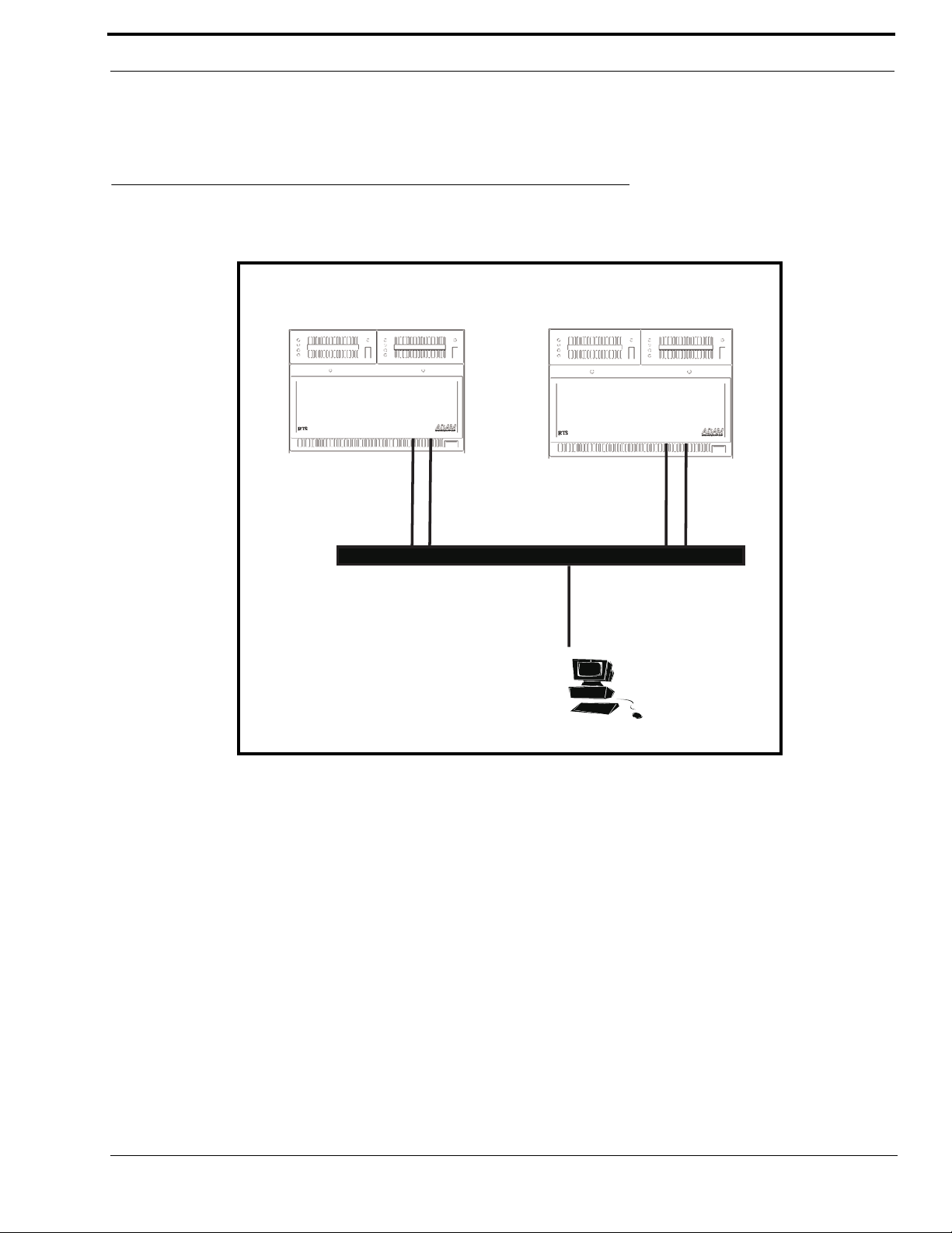
System Diagram
MCII-e
AZedit
A
DAM
MCII-e
A
DAM
LAN
MCII-e
MCII-e
32 MB of SDRAM
8Mbytes Configuration Flash
System Diagram
Figure 1. System Diagram - MCII-e Master Controller
5
Page 8
Introduction
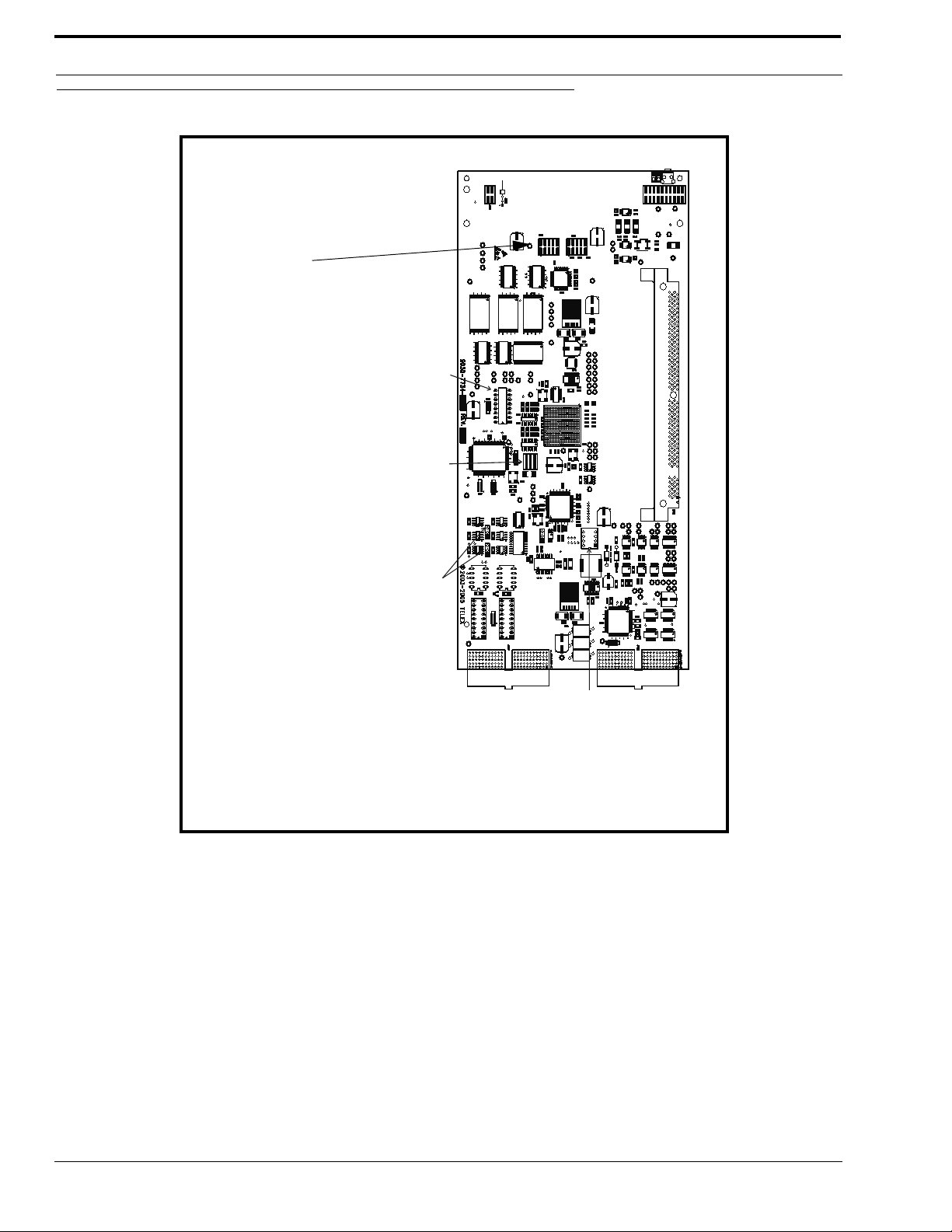
J900
LEDB
SW01
LEDA
SE02
DIP SWITCH BANK
J500 AND J501
RS-232 OR RS-485
FOR J1 AND J2 SERIAL PORTS
J100
DEBUG SERIAL
PORT
J500 (Azedit #1, J1)
J501(Trunking, J2)
RS-232
1 & 2 (default)
2&3
RS-485
2&3
1 & 2 (default)
SE01 -
FOR INTERNAL USE ONLY
ALL DIP SWITCHES MUST BE
IN OFF POSITION
Jumper Settings
For
Programming Use
ONLY!
J801 Pins 1 & 2 must be
shorted.
Pins 3 & 4 must be
shorted.
Reference View - Front Card
Figure 2. MCII-e System Controller Card Board view.
6
Page 9
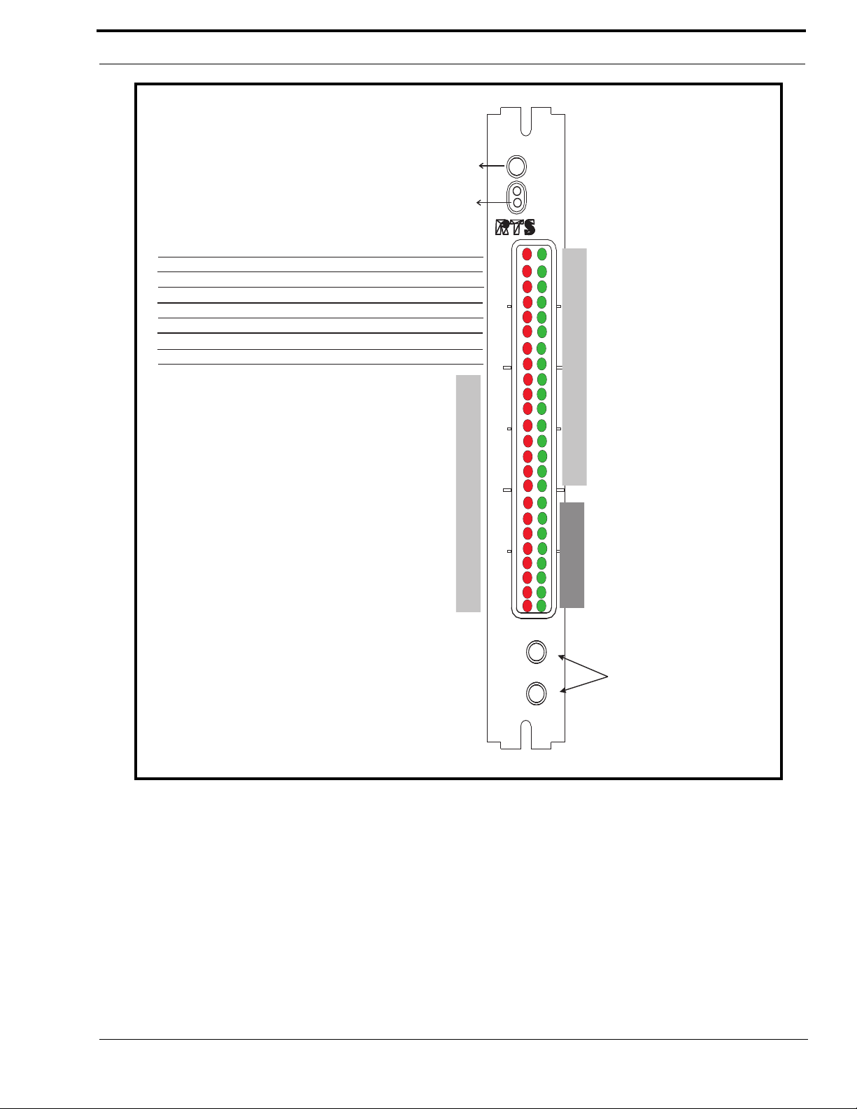
Reference View - Front Card
0
MCIIe
CONTROLLER
SYSTEM
2
1
15
7
1
3
2
5
4
6
11
9
8
10
13
12
14
22
16
18
17
20
19
21
23
TM
RESET
Gives (in binary) the
slot number (1-19) of
the card that the MC
is currently talking with
over the control bus.
Or when all the LEDs are
off, the MC isn’t
talking to a card over
the control bus.
This changes rapidly in
normal operation.
The rest of the green LEDs
show which IO cards are
alive.
For example,
23 = I/O Card in Slot 16 is alive and talking
...
10 = I/O Card in Slot 3 is alive and talking
9 = I/O Card in Slot 2 is alive and talking
8 = I/O Card in Slot 1 is alive and talking
NOTE: There is no LED for I/O card in slot 17.
ON, if acting as the active controller. OFF, if acting as standby.
Flashes while transmitting data on control bus to another card
Flashes while receiving data on control bus from another card
Flashes while transmitting data on private bus to active or standby partner controller
ON, if Trunk Master is alive and connected.
Not used (future)
Not used (future)
Flashes while receiving data on private bus from active or standby partner controller
Illuminated when the corresponding internal task is running
Reset Button
Fail LEDs
Push button 1 Bypass Debug-ONLY
Push Button 2 Unassigned
Figure 3. LED Descriptions for the MCII-e
7
Page 10

Introduction
ETHERNET
J1
J2
LINK
ACT
RJ-45 Ethernet Connection
68-pin SCSI Connection
ON
SE02
1
23
4
5
67
8
Closed
Open
Reference View - Back Card
Figure 4. Back Card
DIP Switches
Figure 5. Dip Switch SE02
DIP Switch 1: Debug Only! Must be in OPEN position.
DIP Switch 2: Sets the baud rate for the AZedit serial connection via J1. By default, AZedit is set for COM 1
and 38,400 kbps (38.4K). The baud rate set in AZedit must match the baud rate setting of the
Master Controllers in ADAM.
DEFAULT = OPEN
OPEN = 9600
CLOSED = 38.4k Baud
DIP Switches 3, 4, and 5: Reserved, keep in OPEN position.
DIP Switch 6: Debug Only! Must be in OPEN position.
DIP Switch 7: Determines Master/Slave Frame in a multi-frame
system.
8
Page 11

DIP Switches
DEFAULT = CLOSED
OPEN = Slave Frame
CLOSED = Master Frame
DIP Switch 8: Debug Only! Must be in OPEN position .
Warning: DIP Switches 1, 6, and 8 should always be left in the OPEN position. These are reserved for debugging
and can have unintended consequences.
9
Page 12

Introduction
Connector Pinouts
68-pin Master
Controller
1 1 RS485 TX/RX3 2 RS232C RX
37 3 RS232C TX
4 4 RS422 TX2 5 Ground
2 6 Ground
38 7 RS422 TX+
35 8 RS485 TX/RX+
68-pin Master
Controller
5 1 RS485 TX/RX36 2 Ground
6 3 RS232C RX
41 5 RS422 TX+
39 6 RS485 TX/RX+
36 7 Ground
40 8 RS232C TX
7 9 RS422 TX-
XCP-ADAM-
Trunking System
XCP-ADAM-
AZedit #1
J-1 of
Assignment 2W
MC
9
J-2 of
Assignment 2W
MC
4Not Used
UIO-256/PAP/LCP
68-pin Master
Controller
8 1 RS485 TX/RX9 2 Ground
44 5 RS422 TX+
42 6 RS485 TX/RX+
9 7 Ground
10 9 RS422 TX-
68-pin Master
Controller
11 1 RS485 TX/RX43 2 Ground
46 5 RS422 TX+
45 6 RS485 TX/RX+
43 7 Ground
12 9 RS422 TX-
J-3 of
XCP-ADAM-MCAssignment 2W
3Not Used
4Not Used
8Not Used
General Purpose
J-4 of
XCP-ADAM-MCAssignment 2W
3Not Used
4Not Used
8Not Used
10
Page 13

Connector Pinouts
General Purpose / Bus Exp.
General Purpose
68-pin Master
Controller
11 1 RS485 TX/RX14 2 Ground
47 6 RS485 TX/RX+
14 7 Ground
General Purpose / Bus Exp.
68-pin Master
Controller
15 1 RS485 TX/RX48 2 Ground
49 6 RS485 TX/RX+
48 7 Ground
J-5 of
XCP-ADAM-
MC
3Not Used
4Not Used
5Not Used
8Not Used
9Not Used
J-6 of
XCP-ADAM-MCAssignment 2W
3Not Used
4Not Used
5Not Used
8Not Used
9Not Used
Assignment 2W
68-pin Master
Controller
16 1 RS485 TX/RX17 2 Ground
50 6 RS485 TX/RX+
17 7 Ground
General Purpose / Bus Exp.
68-pin Master
Controller
18 1 RS485 TX/RX51 2 Ground
52 6 RS485 TX/RX+
51 7 Ground
J-7 of
XCP-ADAM-
MC
3Not Used
4Not Used
5Not Used
8Not Used
9Not Used
J-8 of
XCP-ADAM-
MC
3Not Used
4Not Used
5Not Used
8Not Used
9Not Used
Assignment 2W
Assignment 2W
11
Page 14

Introduction
General Purpose
AZedit #2
68-pin Master
Controller
J-9 of
XCP-ADAM-
MC
Assignment 2W
1Not Used
19 2 Ground
20 3 RS232C RX
4Not Used
5Not Used
6Not Used
19 7 Ground
53 8 RS232C TX
9Not Used
AZedit #3
68-pin Master
Controller
J-10 of
XCP-ADAM-
MC
Assignment 2W
1Not Used
67 2 Ground
21 3 RS232C RX
4Not Used
5Not Used
6Not Used
67 7 Ground
54 8 RS232C TX
9Not Used
J-11 of
Assignment Signal
Controller
68-pin Master
22 1 MI (0) Logical Input (0)
23 2 MI (1) Logical Input (1)
24 3 MI (2) Logical Input (2)
25 4 MI (3) Logical Input (3)
26 5 MI (4) Logical Input (4)
27 6 MI (5) Logical Input (5)
28 7 MI (6) Logical Input (6)
29 8 MI (7) Logical Input (7)
30 9 Ground Ground
31 10 Ground Ground
32 11 Ground Ground
33 12 Ground Ground
34 13 Ground Ground
55 14 MO (0) Logical Output (0)
56 15 MO (1) Logical Output (1)
57 16 MO (2) Logical Output (2)
58 17 MO (3) Logical Output (3)
59 18 MO (4) Logical Output (4)
60 19 MO (5) Logical Output (5)
61 20 MO (6) Logical Output (6)
62 21 MO (7) Logical Output (7)
63 22 Ground Ground
64 23 Ground Ground
65 24 Ground Ground
66 25 Ground Ground
XCP-ADAM-MC
12
Page 15

In this chapter
• System Requirements
• Ethernet Setup for the MCII-e System Controller
• Download Firmware for the MCII-e System Controll er
CHAPTER 2
Configuring the MCII-e
13
Page 16

Configuring the MCII-e
System Requirements
Before you configure your MCII-e System Controller card, verify the following items are updated:
• AZedit v 2.08.01 or later
• AIO-8 v 10.3.4 or later
• AIO-16 v 1.0.0 or later
• Periph-IIe, requires DBX v1.14.0 or later
NOTE: Field upgrade of DBX will requires Boot Code upgrade to version 0.0.3. If the Boot Code is not upgraded, the DBX
card will not work with the MCII-e. Refer to DBX Boot Code Upgrade (pn 38110-472.
Ethernet Setup for MCII-e System Controller
Set the IP Address for the MCII-e System Controller
NOTE: The PC must be running version 2.08.01 or later of AZedit and have an Ethernet card installed. The MCII-e can
support up to 32 concurrent sessions of AZedit on Ethernet.
Verify the MCII-e is connected to the PC using a RS232 (ADAM standard) cable. Connect J1 on the XCP-ADAM-MC to the
COM port on the PC.
NOTE: For more information on Network Basics, see the Basic Networking Guide found at our website
www.telex.com/Intercoms/files.nsf/sitemap#Brochures), under Applications.
If there are two controllers, they must each have their own unique IP Addresses (different from each other and any other
devices sharing the same network).
To connect the Active MCII-e to the PC with a serial cable, do the following:
1. Open AZedit.
The Keypanels/Ports screen appears.
(http://
14
Page 17

Ethernet Setup for MCII-e System Controller
2. From the Option menu, select Ethernet Setup.
The Ethernet Setup screen appears.
3. In the IP Address field, enter the IP Address for the current MCII-e System Controller.
4. In the Network Mask field, enter the Network Mask number for the current MCII-e System Controller.
5. Where appropriate, in the Default Gateway field, enter the Gateway number for the MCII-e System Controller.
NOTE: If the MCII-e will communicate with hosts outside its network, enter the IP address of a host or router which will
serve as the Gateway. Otherwise, if the MCII-e only needs to communicate with the local network, leave the
Default Gateway field at its default setting (0.0.0.0).
The Default Gateway is normally configured the same on both the active and standby MC-II-e System Controller
Cards.
The same screen you use to set the network settings can be used to view the settings as well. You must be
connected using a serial connection via J1 to make changes, but you can view them with any type of AZedit
connection (J1, J9, J10, or Ethernet).
6. Click Apply.
7. Click Close.
The Ethernet Setup window is closed.
8. Connect the MCII-e System Controller to your network with an Ethernet cable.
NOTE: The unique Ethernet MAC address assigned to each MCII-e card during manufacturing is displayed in the field
MAC Address. It is NOT possible to modify this address.
9. Connect the PC to your network with an Ethernet cable.
NOTE: If you do not know these numbers, your system administrator can give you the IP Address and Netmask to use.
Once you have entered the IP Address and Network Mask, do the following:
1. From the Options menu, select Communications.
The Communication screen appears
15
Page 18

Configuring the MCII-e
2. In the Connection area, select the Network radio button.
3. In the IP Address field, either enter the MCII-e IP Address you wish to connect with, or click the Search button .
The search button scans the network for any MCII-e devices. If multiple units are on the network, each will appear in
the list.
4. Select the MCII-e System Controller you wish to work with.
5. Click OK.
The Communications screen closes. The IP Address is configured in AZedit for the MCII-e System Controller.
Download Firmware for the MCII-e System Controller
WARNING: The following procedure will cause one or more brief disruptions in intercom communications. Also, SAVE
your intercom system configuration. From the File menu, select SAVE. Later, if you need to restore the
intercom configuration from disk, use Send File in the Online Menu.
Before you begin, be sure to verify that SERVER mode has been disabled. Also, it is extremely important to take the Standby
Controller card out of the frame, if one is installed.
NOTE: The Active Master Controller will have the topmost red LED (#23) on in the status window lit.
To download master controller firmware, do the following:
16
Page 19

Download Firmware for the MCII-e System Controller
1. From the Status Menu, select Software Versions.
A popup list appears.
2. From the Software Versions popup list, select Master Controllers.
The Master Controller Version Information screen appears.
3. Right-click the active Master Controller, and then select Download Firmware.
The Firmware Download screen appears.
NOTE: You can als o press Ctrl+Shift+D to open the Firmware Download screen once the Master Controller is
highlighted.
4. From the Firmware Download screen, select the firmware update file. Or use the browse button to navigate where
the new file resides.
5. Click Open.
The firmware update appears in the Download Firmware screen.
6. Click Begin Download.
This process can take as little as 30 seconds with “Fast Ethernet” or as long as five minutes when using a serial
connection at 9600 baud.
NOTE: If there is any disruption in the communications link during the download, you wi ll get an error message. In this
case, repeat the download.
7. When the file has been completely downloaded, the MCII-e System Controller will begin processing the update.
IMPORTANT! Any disruption at this point, such as loss of power, removing or resetting cards may result in Master
Controller failure. If this happens, you will have to return the affected unit for replacement or repair.
The AZedit session goes offline for 15-20 seconds when the card performs a reset. It automatically will reconnect when it is
finished.
When the Master Controller is finished, the new software version will appear in the version field of the Version Status screen.
If you do not have a Standby Master Controller Card, you can skip steps eight and nine.
8. Once the Active Master Controller is updated, remove it from the frame.
9. Insert the Standby Master Controller and repeat steps three through eight.
10. When the Standby Master Controller is finished, insert both controllers and resend your system setup file.
17
Page 20

Configuring the MCII-e
18
Page 21

In this chapter
• Accessories
• AZedit
• UIO-256
• PAP
• LCP
• General Purpose
CHAPTER 3
Accessories
19
Page 22

Accessories
Accessories
figure 6. Connection Diagram. The 68-pin SCSI can be attached to the
XCP-ADAM-MC.
NOTE: AZedit sessions are only enabled on J9 or J10 when the advanced communication boxes are enabled from
“communications” screen and the correct baud rates are configured.
XCP-ADAM-MC Master Controller Breakout Panel
The XCP-ADAM-MC Breakout Panel allows many different peripherals to be connected to the master controller of an ADAM
Intercom System, such as AZedit, trunking systems, UIOs, PAPs, LCPs, GPI/Os, etc. For the breakout panel pinouts, see pages
9-15.
AZedit
AZedit is a Windows®-based, full-featured configuration software, providing online and offline configuration capabilities. It
gives you the ability to manage multiple intercom systems, assign and reassign users to dif ferent ports, as well as dynamically
add hardware to your system setup without jumper changes, rewiring, or taking the system offline. AZedit has the capability to
load pre-set configuration files, which means configurations saved to a disk can be uploaded to the “live” application at
anytime, without interruption.
The XCP-ADAM-MC breakout panel has three DB-9 connectors that can be used to connect to AZedit (AZedit #1, #2, and
#3).
Trunking Systems
The RTS™ Trun king System manages intercommunications between separate intercom systems using intercom ports that
have been reserved and interconnected between the intercom systems with devices in other frames. Keypanels or other data
devices can then communicate with devices in other frames.
UIO-256
Each UIO-256 provides 16 GPI inputs and16 GPI outputs. The GPI inputs can be used just like keypanel keys to activate
intercom ports, party lines, relays, etc. Each relay output provides a choice of normal open and normal closed contacts. The
20
Page 23

Accessories
relays can be assigned for activation from keypanel keys, and can be used to control lighting, or to key remote transmitters,
paging systems, etc.
PAP
Program Assist Panels provide a fast and easy method of selecting any of several program sources (connected to input ports of
the intercom system) for use with the IFB outputs feature of the intercom system.
LCP
The LCP panel (Level Control Panel) combines the functionality of three products into one. The LCP allows you to adjust
analog input and output gains, assign sources to IFB outputs and make changes on the fly, and to add members to a party line
on the fly.
GPI/O (General Purpose Input/Output)
J11 provides 8 general purpose control inputs and 8 general purpose control outputs. The control inp ut s ca n be used just like
keypanel keys to activate intercom port s, party lines, relays, etc. The control outputs are open-collector, active-low outputs.
They can be activated by keypanel keys and can be used to control lighting, to key a remote transmitter, to activate a paging
system, etc.
Pin-outs for the digital inputs and outputs are summarized in the table on page 15.
21
Page 24

Accessories
22
Page 25

T runking and the MCII-e System
In this chapter
• Enable Trunk Support for MCII-e System Controller Card
• Connect MCII-e to the Trunk Master (Data)
• Configure TrunkEdit and AZedit to Communicate with the MCII-e System Controller Card
CHAPTER 4
23
Page 26

Trunking and the MCII-e System
Trunking and the MCII-e System Controller
Trunking allows one intercom system to communicate with another remote intercom system with devices in other frames. For
example, a user in New York can talk to a user in Los Angeles if the systems they are using are trunked together. T runking can
be configured to work with cables, fiber optics, voice over internet protocol, or any form of audio/data transfer media, to allow
communication between systems.
To trunk the MCII-e System Controller Card, do the following:
ENABLE TRUNK SUPPORT IN AZEDIT
1. From the AZedit main menu, select Options.
The Options sub-menu appears.
2. From the Options sub-menu, select Preferences.
The Applications Preferences screen appears.
3. On the Applications Preferences screen, click the Advanced tab.
The Advanced screen appear.
4. On the Advanced screen, select Enable trunking support.
5. Click OK to save the change and close the screen. Or, click Apply to save the change and leave the screen open.
When your system has limited bandwidth, you want to set the Allow for Remote T runk Master. By setting this option, the baud
rate is changed to 9600 baud, instead of the default, 38.4K.
To enable the Remote Trunk Master, do the following:
WARNING!: Enabling this option will cause the system to reset. All data will be erased in the frame. Be s ure to save
your system setup to disk before performing this task.
1. Remove the Standby Master Contoller.
2. From the AZedit main menu, select Options.
The Options sub-menu appears.
3. From the Options sub-menu, select Intercom Configuration.
The Intercom Configuration screen appears.
4. On the Intercom Configuration screen, click the Options tab.
The Options screen appears.
5. On the Options screen, select Allow for remote trunk master.
6. Click Test to verify the intercom will accept the new settings.
7. Click Apply.
The intercom will stop communicating with AZedit, reconfigure itself, and then reset.
8. Resend the current setup.
9. Replace the standby contr o ller.
It will automatically reconfigure itself to match the new settings.
CONNECT THE MCII-e TO THE TRUNK MASTER (DATA)
To connect MCII-e to the Trunk Master, do the following:
1. Connect the MCII-e System Controller Card data connecto r to on e of the eight DB-9 connecti ons on the ICP-2000.
CONFIGURE THE TRUNKMASTER TO COMMUNICATE WITH
THE MCII-e SYSTEM CONTROLLER CARD
24
Page 27

Trunking and the MCII-e System Controller
To setup the TrunkMaster to be able to communicate with MCII-e, do the following:
1. Open TrunkEdit.
2. In the left navigation, open the Intercom slide screen.
The Intercom navigation panel displays.
3. From the Intercom navigation, select Setup.
The Intercom Setup screen appears.
4. In the Intercom Setup screen, enter the Intercom System Name (i.e.; ADAM) in the appropriate ICOM port (for
example, if the MCII-e System Controller is cabled to the ICP-2000’s J4 connector, then in the Intercom Setup
screen, enter the MCII-e’s machine name in the line which corresponds with the COM port #4 field).
5. Select the Baud Rate field and enter the baud rate to match the baud setting of the Intercom Trunking port (38.4K or
9600).
6. When you are finished, click the Send button to send the changes to the Trunk Master. When the changes are sent to
the Trunk Master, the MCII-e connects to the Trunk Master and uploads the remote ports. Once the MCII-e has
uploaded this data, it sends its port alphas to the Trunk Master.
In AZedit
1. Open AZedit.
2. On the main screen, select the port you want to make available remotely..
3. In the Scroll Enable field, select Trunk and AZedit.
By enabling Trunk and AZedit on this port, remote users will display in AZedit and remote keypanel users will be able
to see enabled ports.
NOTE: We recommend that you only enable user positions that will be used by remote systems.
4. Send the changes to AZedit.
25
Page 28

Trunking and the MCII-e System
In TrunkEdit - Define the trunk line
NOTE: We recommend you map out your system before defining the trunk lines.
Defining the trunk line shows where a trunk line begins and ends, as well as shows the audio connections between frames.
To define trunk lines, do the following:
1. Open TrunkEdit.
2. In the left navigation, open the Trunk slide screen.
The Trunk Definitions for: All Intercoms panel displays.
3. In the ICOM 1 field, enter the intercom name of one end of the trunk connection (i.e.; ADAM).
4. In the Port Field, enter the port number where ICOM1 is assigned (i.e.; N014). Or, in the Alpha field, enter the
Alpha of the ICOM1 system (i.e.; N014).
5. In the ICOM2 field, enter the name of the system ICOM1 is linked to (i.e.; INT1).
6. In the Port field, enter the port number where ICOM2 is assigned (i.e.; N005). Or , in the Alpha field, enter the alpha
of the ICOM2 system.
7. Once finished with all your definitions, Send the changes to the TrunkMaster.
In AZedit
Once you are finished defining the trunk lines of your system, you can use AZedit to make key assignments for the keypanels.
With Trunking enabled, you will be able to see all trunked system and their ports enabled in AZedit.
26
 Loading...