

Page 1
ADAMTMADVANCED DIGITAL AUDIO MATRIX
USER INSTRUCTIONS
MODEL LCP-100 LEVEL CONTROL PANEL
®
LCP-100
EXP. DATAIN
EXP. DATAOUT
General Description
The LCP-100 Level Control Panel connects to
a KP-9X Keypanel or EKP-9X Expansion Panel. It
lets you adjust individual channel listen levels.
The LCP-100 works only with the ADAM and
ADAM CS Intercom Systems. It is not compatible
with the earlier CS9000 Series Intercoms.
Note: Due to controller bus limitations, no more than
3 level control panels and 2 expansion panels should
be daisy-chained from a keypanel.
Keypanel Firmware Update
A keypanel firmaware update has been provided with
your LCP-100. This must be installed in the keypanel
for proper operation with the LCP-100. Update the
keypanel firmware as follows:
1. Unplug the keypanel power cord.
2. Remove the top cover.
®
Connections and Positioning
For connections, refer to the figures on the reverse
side of this sheet. For ease of use, when positioning
the components it may help to locate each level control panel directly above or below the keypanel or expansion panel that it will be used with. Otherwise,
you may wish to label each LCP control knob according to the key assignment alphas on the keypanel or
expansion panel.
Operation
To adjust a listen level, first activate the listen key for
that channel. While monitoring the level in your keypanel speaker or headphones, adjust the corresponding knob on the LCP.
Note The LCP can only be used to adjust the level
for listen keys that are assigned to ports or
party lines. Levels for IFB’s, ISO’s, and special lists are not adjustable.
3. Use normal precautions about handling staticsensitive devices. Remove the old IC U305 from
the keypanel circuit board and install the new IC.
4. Replace the top cover and reconnect power.
9330-7616-000, Rev A 1/97
™
Page 2
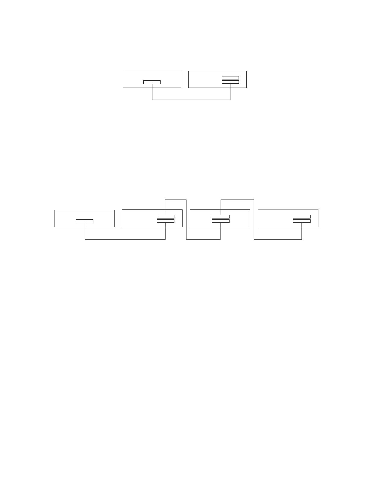
KP-95\96\97
LCP-100
EXPANSION
EXP. DATA IN
EXP. DATA OUT
Figure 1. Simple interconnection of one keypanel and one LCP-100
KP-95\96\97
EXPANSION
EXP. DATA IN
EXP. DATA OUT
LCP-100
EKP-95\96\97*
CONTROL
LCP-100
EXP. DATA IN
EXP. DATA OUT
* The two CONTROL connectorson an EKP arewired in parallel. Either one may be used for input or output.
Figure 2. Typical interconnections when using EKP expansion panels. Note: no more than two expansion
panels should be connected when using LCP’s.
 Loading...