

Page 1

Instruction Sheet
ACS-101
Amplified Broadband UHF Combiner-Splitter
General Description
The ACS-101 (Antenna Combiner Splitter 10 to 1) is an
amplified and filtered broadband splitter-combiner. It allows up
to 10 base stations to use only one (1) transmit and one(1)
receive antenna.
The antenna combiner section contains innovative hybrid
coupling, amplifying and matching technology to combine 10
transmitters to one (1) output with very low intermod distortion.
The antenna splitter section has broadband input filtering and
amplification to maintain signal levels through the splitters.
High output isolation between pots is also achieved.
The industrial strength power supply of the ACS-101 supplies
voltage and current to two (2) outputs on the product. Each
output can supply up to 5Amps at 12VDC.
IMPORTANT: Using products that deliver more than
50mW of transmit power to the ACS-101
is not recommended, and may cause
damage to the unit or accompanying gear.
Specifications
Overall
Antenna Connectors....................................................................................................................................Standard TNC Receptacles
AC Input Power .....................................................................................................................................100–120VAC, 60Hz, 6A max.
AC Input Fuse .............................................................................................................................................................10A, 250V, 3AG
DC Output Power...................................................................................................................................... 12VDC, 5A for each output
DC Output Jacks .......................................................................................................................................Two, 5.5mm x 2.1mm Jacks
DC Output Fuses............................................................................................................................................ 5A, 250V, 5mm x 20mm
Size..................................................................................................... 3.50” (88.9mm) H x 16.75” (426mm) W x 14.63” (372mm) D
Weight ...................................................................................................................................................................10lbs., 4oz. (4.65kg)
Antenna Splitter
Frequency Range..............................................................................................................................................................614–746MHz
Output IP3 ................................................................................................................................................................ Greater than 30dB
Net Gain ............................................................................................................................................................................. 0dB, typical
Noise Figure.................................................................................................................................................................. less than 4.5dB
Minimum Isolation....................................................... 20dB between adjacent ports; greater than 20dB between non-adjacent ports
Antenna Combiner
Frequency Range..............................................................................................................................................................470–608MHz
Net Gain ................................................................................................................................................................................. 0dB max.
Noise Figure...................................................................................................................................................................... 10dB typical
Output IP3 ......................................................................................................................-55dBc @ +17dBm input on each transmitter
Bosch Security Systems, Inc.
Installation Sheet
F.01U.XXX.XXX
Rev. 0X
Page 2

ACS-101 Product Features
A
CS-
1
01
UHF Antenna Splitter/Combiner
POWER - GREEN
OVERHEAT- RED
RadioCom
1
• Ideal for use with BTR-1, BTR-500, BTR-600, BTR-700 wireless intercom systems.
• Two (2) power outputs to supply up to 10 transceivers (5 on each daisy-chain run) which makes large
systems easier to implement
• Standard IEC 320 power input connector
• 115VAC or 230VAC operation
• High Quality TNC connectors for consistent impedance across the entire frequency range
• Rack mount brackets included for 19” (482.6mm) rack
Connections, Fuses and Indicators
Instruction Sheet
FIGURE 4. ACS-101 Front Panel
1. Power/OverHeat Light
4
Bosch Security Systems, Inc.
Green - The unit has power
Red - The unit has overheated and the combiner amplifiers have shutdown. There is a
sensor on the combiner amplifier heatsink that senses if the heat rises above 75°.C
(167°F)
Installation Sheet
F.01U.XXX.XXX
Rev. 0X
Page 3
Instruction Sheet
TRANSMIT
ANTENNA
FUSE
5A SLOW BLOW
DC OUT
12V 5A
FUSE
5A SLOW BLOW
DC OUT
12V 5A
RECEIVE
ANTENNA
TRANSMIT
RECEIVE
8
2
4
3
5
2
4
7
6
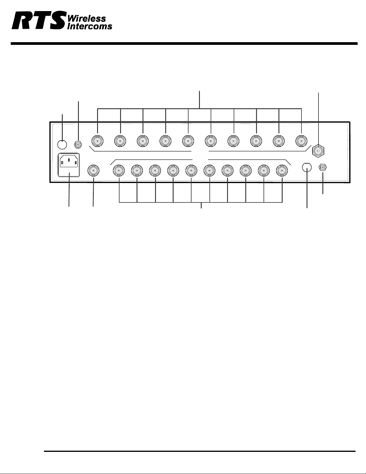
FIGURE 5. ACS-101 Rear View
2. DC Outlet Fuses 5Amp, SlowBlow, 250VDC. Size 3AG
3. IEC Power Inlet with Fuse IEC-320 power inlet with a 10Amp, 250VDC Fuse. Size is 5mm by 20mm.
4. DC Power Output Jacks Threaded 5.5mm x 2.1mm Jacks. 12 VDC up to 5Amps is available at each jack.
5. Receive Antenna Jack This TNC female connector is where the recive antenna connects.
6. Receive Splitter Jacks These 10 TNC female connectors are the outputs for the receive signals.
NOTE: All unused jacks should be terminated with 50 Ohm loads. See
Accessories on page X.
7. Transmit Combiner Jacks These 10 TNC female connectors are the inputs for the transmitters.
8. Transmit Antenna Jack This TNC female connector is where the transmit antenna connects.
Bosch Security Systems, Inc.
Installation Sheet
F.01U.XXX.XXX
5
Rev. 0X
Page 4

Instruction Sheet
TRANSMIT
ANTENNA
FUSE
5ASLOW BLOW
DC OUT
12V 5A
FUSE
5ASLOW BLOW
DC OUT
12V 5A
RECEIVE
ANTENNA
TRANSMIT
RECEIVE
Rx
Tx
Power
Rx
Tx
Power
Rx
Tx
Power
Rx
Tx
Power
Rx
Tx
Power
RECEIVE
ANTENNA
TRANSMITTER
ANTENNA
Rx
Tx
Power
Rx
Tx
Power
Rx
Tx
Power
Rx
Tx
Power
Rx
Tx
Power
Rx
Tx
Power
System Configuration
Figure 6 illustrates the typical system configuration using the ACS-101 to support 10 BTR-1 base stations.
FIGURE 6. System Configuration
6
Bosch Security Systems, Inc.
Installation Sheet
F.01U.XXX.XXX
Rev. 0X
Page 5

Instruction Sheet
T
elex
T
THIS END TOWARD TRANSMITTER
ALP-450
ex
el
R
Antenna Requirements
The ACS-101 may be used with a variety of antennas. For best results, use a pair of ALP-450 directional log periodic antennas
(See Figure 5Figure 2.) or, the ALP-600 Bi-directional log periodic antenna (See Figure 1).
Good results may also be obtained with ½ wave antennas (See Figure 3. All antennas are sold separately.
When using ½ wave antennas, we recommend using the higher frequency model when the receivers operate in more than one (1)
band. If the receivers are more than one (1) band apart, such as yellow and white, we strongly recommend using the ALP-450, or
ALP-600 depending on the application.
Place the ACS-101 with antennas in a location that is in direct view of the beltpacks for best results.
FIGURE 1. ALP-600
FIGURE 2. ALP-450
FIGURE 3. ½ Wave Antenna
Bosch Security Systems, Inc.
Installation Sheet
F.01U.XXX.XXX
7
Rev. 0X
Page 6

Instruction Sheet
Antenna Placement for Optimum Range and Rack Mounting
For maximum range and when rack mounting, the antennas must be remotely located.
The ALP-450 and the ALP-600 antennas come complete with a variety of mounting hardware and 10ft. (3m) of low loss coaxial
cable. A combination mounting bracket with 10ft of coaxial cable is available for ½ wave antennas (Model No. AB-2).
Antennas should be places in a location with a clear signal path to the beltpacks. This path should be as short and free of
obstruction as possible. Obstructions, such as walls, ceilings, and metal objects, reduce range and performance.
FIGURE 7. Rack Mount Brackets
Rack Mounting
Rack mount brackets are supplied with the ACS-101.
To attach the brackets, do the following:
1. Align the rack mount bracket with the holes on the side of the unit (Figure 8).
2. Install flat head machine screws in two (2) holes.
3. Tighten securely.
4. Repeat, step 1 through 3 on the other side of the unit.
NOTE: For best alignment, perform the above steps while the unit and rack brackets are setting on a flat surface.
5. Insert the unit into a 19” rack enclosure and insert four (4) screws (not supplied) in each corner of the rack mount brackets
and secure.
Coax Cable
For best results, it is recommended that cable losses be kept under 4dB. Every 3dB of signal loss results in a system operating
distance reduction of 25%.
See the accessories section of this sheet for special low loss cable assemblies.
8
Bosch Security Systems, Inc.
Installation Sheet
F.01U.XXX.XXX
Rev. 0X
Page 7

Instruction Sheet
T
elex
T
THIS END TOWARD TRANSMITTER
ALP-450
ex
el
R
MICROPHONE STAND
MOUNTING
ACS-101 Accessories and Replacement Parts
ALP-600
480-800MHz Bi-Directional log periodic antenna. Includes
mounting hardware and 10ft. (3m) coaxial cable with TNC
connectors.
Order No. - 878896
Low Loss Coaxial Antenna Cables with TNC Connectors
450-900 MHz Log Period Antenna. Includes mounting
hardware and 10ft (3m) coaxial cable with TNC connectors
Order No. 71147000
½ Wave Antenna (CLA-X)
Model Length Order No.
CXU-10 10ft (3m) 690419
CXU-25 25ft (7.6m) 71151-025
CXU-50 50ft (15m) 71151-050
CXU-75 75ft (23m) 71151-075
CXU-100 100ft (30m) 71151-100
TP-2 50 OHM/TNC Dummy Load
(For unused outputs)
Part No.650095
AB-2
Bracket for ½ wave
antenna with 10ft of coax.
Part No.71138000
ALP-450
Model Part No.
CLA-1 870658-1 Blue 520-565MHz
CLA-2 870658-2 Yellow 565-615MHz
CLA-3 870658-3 Red 615-660MHz
CLA-4 870658-4 White 660-690MHz
CLA-5 870658-5 Green 690-725MHz
CLA-6 870658-6 Orange 725-760MHz
CLA-10 870658-10 Tan 470-518MHz
CLA-11 870658-11 Pink 515-548MHz
CLA-12 870658-12 Brown 542-575MHz
Band
Color
Frequency
Bosch Security Systems, Inc.
Installation Sheet
F.01U.XXX.XXX
9
Rev. 0X
Page 8

 Loading...