

RTS 862 Technical Data Manual
TECHNICAL
DATA
PACKAGE
TDP
3511 / O/N 9300-3511-00
Second Edition
/
October 1989
MODEL
862
SYSTEM
INTERCONNECT
RTS
SYSTEMS
1100 West Chestnut Street / Burbank, CA 91506 / Phone 566-6700 / FSCM:
60572
TECHNICAL DATA PACKAGE
Model 862 System Interconnect
PROPRIETARY NOTICE
UNPACKING INFORMATION AND INSPECTION
The information and design disclosed herein were
originated by and are the property of RTS Systems.
RTS Systems reserves all patent, proprietary design,
manufacturing, reproduction, use an sales rights
thereto, and to any article disclosed therein, except to
the extent rights are expressly granted to others.
Immediately upon receipt of the equipment, inspect
the shipping container and the contents
carefully for
any discrepancies or damage. Should there be any,
notify the freight company and the dealer at once.
The shipping Series 4001 IFB System, Model 4001
container should contain the following components:
COPYRIGHT NOTICE
Ordering Number
9000-3062-00
Copyright 1988 by RTS Systems, Burbank, California,
USA.
All
rights reserved. Reproduction in whole or
in
part without written permission from RTS Systems
is prohibited
TECHNICAL DATA PACKAGE, 'ITM3511
Model 862 System Interconnect
Printing History
First Edition: December 1983
Second Edition: October 1989
This manual is published by the ~n~ineering
Department of RTS Systems, which is responsible for
its contents.
Written by: Stan Hubler
Edited by: Sheryl D. Thompson
Address all communication regarding this publication
to:
Director of Engineering
RTS Systems
1100 West Chestnut Street
Burbank,
CA
91506 USA
RTS Systems
Part Number Description
1
9010-3062-00 Model 862 System
Interconnect
1
9300-3511-00 Technical Data Package
RTS Systems, Burbank, CA 91506
/
FSCM: 60572 TDP35111 Second Edition, October 1989
Page
2
TECHNICAL DATA PACKAGE
Model 862 System Interconnect
TABLE
OF
CONTENTS
m
Unpacking Information
......................................................................................................................................
2
.................................................................................................................................................
Table Of Contents
3
Warranty
..........................................................................................................................................................
4
..........................................................................................................................................
Shipping Information 4
SECTION
1:
INTRODUCTION
.............................................................................................................
1.1
Introduction & Description
.'....
5
1.
2 Specifications
.................................................................................................................................
6
SECTION
2:
PARTS LIST
......................................................................................................................................
2.1 Introduction 6
.............................................................................................................................
2.2 How To Obtain Parts 6
2.3 Shipping List. Model 862
.......................................................................................................................
6
2.4 Final Assembly. Model 862
.................................................................................................................
7
.............................................................................................................................
2.5 Back panel Assembly 7
2.6 Printed Circuit Assembly. Model 862 (Upper)
..................................................................................
8
2.7 Printed Circuit Assembly, Model 862 (Lower)
...................................................................................
8
...........................................
2.8 Printed Circuit Assembly. Motherboard. Model 862
.....................
..
8
2.9 Front Panel. Model 862
.........................................................................................................................
9
SECTION
3:
LIST
OF
DRAWINGS
Schematic Diagram. SA/IFB/PGM. Input Board (Upper) Model 862
...................................................
11
Schematic Diagram. SA/IFB Output Board (Lower). Model 862
..............................................................
12
Assembly Diagram. P.C. Board. SA/IFB/PGM Inputs (Upper) Board
.
Model 862
...............................
13
Assembly Diagram. P.C. Board. SA/IFB Outputs (Lower) Board . Model 862
....................................
14
Schematic Diagram. Model 862. sheet
1
through
3
..............................................................................
15-17
...........................................................
Assembly Drawing. P.C.B. Board. System Interconnect. Model 862
18
.................................................................
Assembly Drawing. Top Assy. System Interconnect. Model 862
19
RTS Systems. Burbank.
CA
91506 / FSCM: 60572 TDP3511/ Second Edition. October 1989
Page 3
TECHNICAL DATA PACKAGE
Model
862
System Interconnect
RTS SYSTEMS' LIMITED WARRANTY
RETURN
SHIPPING INSTRUCTIONS
The products of RTS Systems, a California
corporation, are warranted to
be
free from defects
in
materials and workmanship for a period of one year
from the date of sale.
RTS Systems' sole obligation during the warranty
period is to provide, without charge, parts and labor
necessary to remedy covered defects appearing in
products returned prepaid to RTS Systems, 1100
W.
Chestnut Street, Burbank, California, 91506, U.S.A..
This warranty does not cover any defect, malfunction
or failure caused beyond the control of RTS Systems,
including unreasonable or negligent operation, abuse,
accident, failure to follow instructions in this Manual,
defective or improper associated equipment, attempts
at modification and repair not authorized by RTS
Systems, and shipping damage. Products with their
serial numbers removed or effaced are not covered by
this warranty.
To obtain warranty service, follow the procedures
entitled "PROCEDURE FOR RETURNS" and
"SHIPPING TO MANUFACTURER FOR REPAIR
OR ADJUSTMENT" listed below.
This warranty is the sole and exclusive e ress
warranty given with respect to RTS Systems' pro
"B
ucts.
It is the responsibility of the user to determine before
purchase that this product is suitable for the user's
intended purpose.
ANY
AND
ALL IMPLIED WARRANTIES,
INCLUDING THE IMPLIED WARRANTY OF
MERCHANTABILITY ARE LIMITED TO THE
DURATION OF THIS EXPRESS LIMITED
WARRANTY.
NEITHER RTS SYSTEMS NOR THE DEALER
WHO SELLS RTS SYSTEMS' PRODUCTS IS
LIABLE FOR INCIDENTAL OR
CONSEQUENTIAL DAMAGES OF
ANY
KIND.
Procedure For Returns:
If repair is necessary, contact the dealer where this
unit was purchased.
If repair through the dealer is not possible, phone the
RTS Systems Customer Service Department, located
at the factory, as directed below. They
will
issue a
Return Authorization Number
DO NOT RETURN
ANY
EOUIPMENT TO THE
FACTORY WlTHOUT FIRST OBTAINING A
RETURN AUTHORIZATION NUMBER,
Be prepared to provide your company's name,
address, phone number, a person to contact regarding
the repair, the type and quantity of equipment, a
description of the defect, and the serial number@).
Questions regarding returns for repair should be
directed to:
Customer Service Department
RTS Systems
1100
W.
Chestnut St.
Burbank,
CA
91506, U.SA.
Telephone: (818) 566-6700
Telex: 194855
Telefax: (818) 843-7953
SHIPPING TO MANUFACTURER FOR REPAIR
OR ADJUSTMENT
All shipments of RTS Systems, equipment should be
pre~aid via United Parcel Service or the best available
shipper. The equipment should be shipped
in
the
original packing carton; if that is not available, use any
suitable container that is rigid and of adequate size. If
a substitute container is used, the equipment should
be wrapped in paper and surrounded with at least
four inches of excelsior or similar shock-absorbing
material. All shipments should be directed to the
attention of the Customer Service Department and
must include the Return Authorization Number.
Upon completion of repairs equipment
will
be
returned collect via United Parcel Service or specified
shipper.
RTS Systems, Burbank, CA 91506
/
FSCM: 60572 TDP3511/ Second Edition, October 1989
Page
4
TECHNICAL DATA PACKAGE
Model 862 System Interconnect
SECTION
1:
INTRODUCTION
The Model 862 System Interconnect interfaces with
the Model 802 Master Stations and other external
systems, and equipment. Typically, Model 802 Master
Stations access communications circuits which
include: conference-line and central matrix type
intercom systems, paging systems, telephone lines and
two-way radios. (see drawing AS3062).
The Model 862 System Interconnect enables the
connection of up to twelve Model 802 type intercom
channels; and up to twelve standard 'TW" intercom
system channels. The Model
802
Master Stations
plug into the Model 862 System Interconnect at 51
-
J4 inclusive. The Model 862 converts the twelve
Master Station type channels (two-wire, balanced,
dry) to twelve
"TW"
type channels (two-wire,
unbalanced, 'wet
=
with dc) by using transformer and
capacitive coupling. The
"TW"
circuits are accessed
on rear panel mounted Cpin XLR type connectors:
55 (channels
1,
2, 3) , 56 (channels 4,
5,
6) , 57
(channels 7, 8,9) and 58 (channels 10,
11,
12). These
circuits are directly plug-in compatible with standard
"TW"
intercom lines. The
"TW"
System power supply
(ies) terminate the Master Station type channels. If a
Master Station type channel does not interface to a
"TW" system power supply, a proper termination must
be added. This termination consists of a
200
ohm
resistor and a 10 microfarad capacitor connected in
series. The resistor-capacitor combination is
connected on the unbalanced connector from the
channel pin (to be terminated) to the common pin.
Associated with each Master Station channel is a
"keying" logic type signal which operates a relay in the
Model 862 System Interconnect. There are twelve
such logic signals and they are originated by pressing
a Model 802 'Talk" button. Each of the twelve relays
has a set of single pole double throw contacts
available on one of two rear panel mounted
25-pin
"Dn
type connectors (521, 522). The relay contacts
may be used for control, signalling, or audio switching
functions.
The relays for channels 7 though 12 have an
additional set of audio contacts which are accessed on
six female XLR-3 type input connectors (J9
-
514
inclusive). These circuits are line-level transformer-
balanced and can be used for simple Studio
Announce, Slate Microphone, IFB (Interrupted
FeedBack or program interrupt), and/or similar
functions. (These functions will be common to all
Model 802 Master Stations in the system when they
are equipped with the "Talk Option"). A transformer
balanced, program input (523, AUX PGM IN #2) on
the Model 862 accepts a line level audio signal. This
common program monitoring signal is disrupted to
the "Auxiliary Program Input
#2" on all the Model
802
Master Station in the system.
Additional Details
If more than four Model 802 Master Stations LINE
CONNECTORS are to be connected to the Model
862 System Interconnect, use (a) Model 4025A
1
x
4
Splitter Assembly (s) to parallel the add@onal
incoming cables from the Models 802's. The Model
4025A may be plugged into either the Model 862 or
another Model 4025A. Each Model
802
LINE
CONNECTOR contains
12
balanced audio pairs for
channels
1
through 12. 12 keying limes, 12 keying line
returns and
1
audio program pair (AUX PGM IN
#2).
Functional Details
of
SA/IFB Feature
Normally, in a non-keyed condition, the relays
connect the input female XLR-3 connectors to the
output male XLR-3 connectors. When a talk circuit
key of a given channel is activated, the relay
disconnects the input female XLR-3 connector and
connects the output male connector to that channel's
talk audio from the Mode1
802.
For example, a single
IF3 channel fed audio from channel
7,
also, fed
program audio into 59 should connect a power
amplifier with speaker to J15. When the channel
7
talk button on any Model 802 is pressed, the program
signal is interrupted and audio from that Model 802
will be fed to the power amplifier. When the talk
button is released, the original program signal is
restored.
RTS Systems, Burbank,
CA
91506
/
FSCM:
60572 TDP3511/ Second Edition, October 1989
Page
5
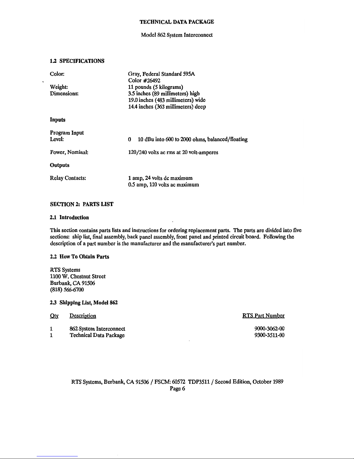
1.2
SPECIFICATIONS
Color:
Weight:
Dimensions:
Inputs
Program Input
Level:
Power, Nominal:
Outputs
Relay Contacts:
TECHNICAL DATA PACKAGE
Model
862
System Interconnect
Gray, Federal Standard 595A
Color
#26492
11
pounds (5 kilograms)
3.5 inches (89 millimeters) high
19.0 inches
(483
millimeters) wide
14.4
inches (363 millimeters) deep
0
10 dBu into
600
to
2000
ohms, balanced/floating
1201240 volts ac rms at
20
volt-amperes
1
amp, 24 volts dc maximum
0.5 amp, 110 volts ac maximum
SECTION
2:
PARTS LIST
2.1
Introduction
This section contains parts lists and instructions for ordering replacement parts. The parts are divided into five
sections: ship lit, final assembly, back panel assembly, front panel and printed circuit board. Following the
description of a part number is the manufacturer and the manufacturer's part number.
2.2
How To
Obtain
Parts
RTS Systems
1100
W.
Chestnut Street
Burbank,
CA
91506
(818) 566-6700
23
Shipping List, Model
862
1
862
System Interconnect
1
Technical Data Package
RTS Part Number
RTS Systems, Burbank,
CA
91506
/
ESCM:
60572
TDP3511/ Second Edition, October 1989
Page
6
 Loading...