

Page 1
SERVICE
I
MODEL
MANUAL
8108
Master Station
1
Series
With Panel Microphone
Without Panel Microphone
800
9360-5729-00 Rev
E
8/97
Page 2
PROPRIETARY NOTICE
The
information and design disclosed
originated by and
Systems resines
niaoufacmin$,
and to any amcle disclosed therein, except to the extent
rights
are
expressly granted to othem.
an
tbc
woDmY
all
nahit
repductioi.
aroOrietv desina.
r$e
herein
of RTS Svstems. RTS
and hes Z&ts thmto.
wm
-
COPYRIGHT NOTICE
NEITHER
SELLS RTS SYSTEMS PRODUCTS IS
INCIDENTAL
ANY
RTS SYSTEMS NOR
OR CONSEQUENTIAL DAMAGES OF
KIND.
THE
DEALER WHO
CUSTOMER SUPPORT
Technical questions should
be
directed
to:
LIABLE
FOR
CopynghtlW6 by RTS Systems. All
R uchon m whole or
permission from RTS Systems is prohibited.
m
pan without prior
rights
resewed.
written
PATENT NOTICE
This equipment contains and uses a design
United States Patent No.
Source for a Multi-urmmal Intercom". This desien
employs a twc-wire to four-wire convener.
4,358,644:
embodied
"A Bilateral Current
in
-
UNPACKING AND INSPECTION
Immediately upon receipt of the equipment, inspect the
shipping container
dimepancies
freight company and the dealer at
and
the
or
damage. Should
contents carefully for any
then
be any,
once.
notify
the
WARRANTY INFORMATION
The
products of
from
defects in materials and workmanship for a
of
three
years
RTS Systems sole obli ation during the warranty
is to provide, without c%arge,
remedy
dd to RTS Svstems.%%%umntv does not cover
by'
control of RTS Systems, includinn unreasonable or
nedimt o~eration.
inhictionj in
defective or improper associated equipment, attempts
modification aid
and ship ing damage. Roducts with the& serial humbek
removecfor effaced
To obtain warranty service, follow the procedures entitled
"Procedure
for Repair or Adjushnent".
This
given with 6-t to RTS Systems produk. It is the
responsibility of
that
ANY
INCL.UDING
mered
defect
warrantv
this product is suitable for the user's intended purpose.
AND
MERCHANTABILITY
DURATION
WARRANTY.
RTS
Systems
from
the
defects
malfu6kion or
~~~
abuse.
the
Senice~Manual or
revair
are
For Rerums" and "Shiminn to Manufacturer
is
the sole and exclusive exmess warrantv
the
urn to dnamine before
ALL
IMPLlED
THE
IMPLIED
OF
THIS
are
warranted to be
date
of sale.
pam
and labor necessary to
-'
g in products returned
.
failure
acci&t
not
autludd
not covered by this w-ty.
----
caused beyond the
failure to follow
the
User
bv RTS Svitems.
--
-
W-,
WARRANTY
ARE
LIMITED
EXPRESS
TO
LIMITED
free
period
period
---
~&ual,
at
purchase
OF
TEE
'
RETURN SHIPPING INSTRUCTIONS
PROCEDURE FOR RETURNS
If
a
repair
is necessary, contact
pure-
was
E%KNAA ORIZATION
DO
TO
OBTAlMNG A RETURN AUTBOREATION.
Be
phone number, a
the
problem and
SHIPPING TO MANUFA- FOR REPAIR OR
ADJUSTMENT
AU
made via United Parcel Service
shimr.
ori&al &king carton;lfhat is not available,=ise an
suitable container that is rigid and of adequate size. da
substitute container is
wrapped
of excelsior or
shipments must be sent to the followinn address and must
include the Return Authorization.
Upon completion of any
returned vla United k=ice or
collect
h
NOT
TEE
prepared
type
and quanti'y of
shipments of RTS Systems equipment should
maid.
in paper and surmunded.dth
Customer Service Deparrment
Telex Communications, Incorporated
West 1st Street
Blue
the dealer
RETURN
FACTORY WrmOIJT
to provide
ANY
the
person
the
senal
number(s).
The ffluioment should
used
similar
shock-abatii marerial.
Earth,
MN
the
dealer where this unit
is
not possible, obtain a
from:
EQUIPMENT
DIRECnY
FIRST
company name, address,
to contact regardink the
equipment,
the eauiDmedt should be
e
descnption%d
or
the
best available
be
shid
at
least four inches
-
56013
U.S.A.
the equipment will
specified
be
in
-
AU
be
shipper
the
--
Page 3
TABLE
OF CONTENTS
Proprietary Notice
copyright Notia
Pateat
Norice
..............................................................................................................
Printing
Unpacking
Quick
Table
Warranty
Shipping
SECTION
Ref
SECTION
Ref
Histoty
Table
Of
...........................................................................................................
Infdon
of
Content8
Content6
...................................................................................................................
Infotmatk
1:
DESCRTPTION
.
No
.
2:
INSTAUATION
. No .
........................................................................................................
.........................................................................................................
and
Inspection
................................................................................
.................................................................................................
........................................................................................................
....................................................................................................
AND
SPECIFICATIONS
m
l2kmstim.
Model
Modal
"
Inputs
md
outputs
810B Specificdons
865
Speci ficatiolvl
........................................................................
...............................................................
......................................................................
2
2
2
2
2
2
3
8
8
10
10
11
SECTION
Mecbaaical
Power
Wim
System Tumination
J:
OPERATING lNSlRUCTIONS
Configurations & System Compnrisons
Sidetone
Level
Chanuel
Squawk Style Systsms
Receive
Talk Chaanel
Dip Switch
'Stringing'
Squawk
lkdemxe
Model
Tennillation
~~OB-CL
Talk
Listen
.........................................................................................
...............................................................................................
and
Cable
cademtiom
...............................................................................
AdjusEmnts
Adj-ts
Output
.............................................................................
................................................................................
Signal hl 14
............................................................................
Chpnael
System
810B-CL
Selection
Selection
&signum&
SquPwk
Style Systems
...........................................................................
..................................................................
Sfations TO@M 20
Pin
in&m
.............................
........................................................................................
-tim
Assigmlmts
Assignments
.................................................................................
...............................................................................
.................................................................
........................................................
....................................................................
.......................................................................
.........................................................
U)
.............................................................
........................................................................
...................................................
-.-
TO
TW
system
.....................................................
13
13
13
13
14
14
14
17
17
17
20
21
21
21
21
22
22
Page
3
Page 4
TABLE
OF CONTENTS
(ewtinued)
SECTION
3.3.6
3.3.7 Dip Switch
3.4 Model 810B-5Cn
3.4.1 810B-5CIZ
3.4.2 8lOB-5
3.4.3 8lOB.5
3.4.4
3.4.5 81OB-5Cll
3.5
3.5.1 810B-AA
3.5.2 81OB-M
3.5.3 810B-AA Tally
3.5.4 81OBB-AA
3.6
3.7 810B
3.7.1
3.7.2 Goosead Minophons
3.7.3
3.7.4
3.7.5
3.7.6
3.7.7 Unswitched Microphone
3.7.8
3.7.9
3.7.10
3.7.11 Microphone
3.7.12 Microphone
3.7.13
3.7.14
3.7.15 Speaker
3.7.16 Speaker
3.8 Special
3.8.1
3.8.2
3.8.3
3.8.4
3.8.5 /&itrary System
3.8.6
3.8.7
3: OPERATING INslraUCXLONS
Self
Tdly
...........................................................................................
kssignmu~ts
................................................................................
Tdk
kssivts
Cn.
Listm
Assignmars
Cn.
T*
kssiw
Dip Switch
M.trix
Combinntions
Dynsmic
Alternnte
Alternnte
Extemd
Remote
Remote
Listen
Extd
Am
Instaat
.
bfmmum
A*
Interface
Interfict
OperPting
Rear
Ansignmmts
Inkuwmedon
Systsm
T&
Listm
Dip
FePtures
Micropb
Electret
Dynamic
Headset
Mi-
Speaker Switch
Outfrdk
SpaLer Output
Limiter
Level
Spealrer
.
On
Microphone
Dim
Enable
Dim
Mjwtmea
Applications
Volume
B&
TO
Md
To
TW
Controls
Panel
Connections
Coaf~on
Assimts
Assignmentrr
Assigm~~ts
Switch
Systems
.........................................................................
......................................................................................
Headset
Microphone
Mimophone
.................................................................................
Switch
In
................................................................................
(R43) 39
Control
(Sl-3) 39
On
(Sl-1
..........................................................................
.................................................................................
................................................................................
802
Intacom
Inkranmedon
................................................................................
(-
23
..................................................................
..................................................................
................................................................
.................................................................
......................................................................
To
TW
Syh
(81OB-M)
.................................................
.....................................................
.....................................................................
...................................................................
....................................................................
kssi&anm~ts
.......................................................
..................................................................
(Optid)
.............................................................
ComwAion
Gd
...................................................
...................................................
.....................................................................
Output
...............................................................
..........................................................................
.........................................................................
23
27
27
27
27
27
27
30
31
31
32
32
33
33
33
34
34
34
34
35
35
35
37
38
......................................................................
...............................................................
(R81) 39
..........................................................................
..................................................................
(S1-4) 39
and
S1-2)
.........................................................
t.
.......................................................................
Mnster Station 42
Speaker Station 43
...................................................
...................................................
Requh-
.............................................
.........................................................................
39
39
41
41
42
43
45
46
SECTION
Ref . No
4.1
4.2 Sys~mThaory 48
4.2.1 Signal
4.2.2
4.3 Modal 810B
4.4
.
4:
THEORY
T&
Intmdu&on
T@
Operating
OF OPERATION
........................................................................................
.....................................................................................
.........................................................................................
Path
.........................................................................................
hth~
Ovadl
Dibca
Fumtkd
ad
Special
Mfion
Considerations
.................................................
.............................................
ks%
48
48
48
50
50
Page 5
TABLE
OF
CONTENTS
(continued)
SECTION
Ref
.
No
.
5.1
5.2
5.3
5.3.1
5.3.2
5.4
5.4.1
5.4.2
5.4.3
5.4.3.1
5.4.4
5.4.4.1
5.4.5
5.4.6
5.4.7
5.4.8
5.4.9
5.4.10
5.4.11
5.4.12
5.4.13
SECTION
5:
MAINTENANCE
m!?
Inhdwtim
Setvic8
Gd
snwr-
ClePning
Test
set
Po~g Supply
Microphone
USM
Line
Listm
ListcaSumAmp
spaLa
Auto
Sm
H*
Listm
Continuity
Logic
Fi
6:
LISTS
Infomation
MaiUbnsocs
............................................................................................
Procedurt
Up
...............................................................................................
O~iput
Driver
Select.
Amp,
Sm
Dim
In/Tdk
Fdm
AdjustmatP
OF
REPLACEABLE
........................................................................................
...............................................................................
............................................................................
OM
.............................................................................
....................................................................................
......................................................................................
Preamplifier
&
Limiter
.........................................................
.......................................................................................
Outputs
..............................................................................
......................................................................................
...................................................................................
Extend
ON
(R86)
Amp
Out
Checks
SpePlrcr
Function
Jack
aad
Speplrsr
*-Off
Switch
........................
.....................................................................
...............................................................................
..................................................................................
Jumpem
.....................................................................
................................................................................
...................................................................................
............................................................................
PARTS
bl!?
51
51
51
51
51
51
55
55
55
55
55
55
56
56
56
56
57
57
57
57
57
6.1
6.1.1
6.2
6.3
6.3.1
6.3.2
6.4
6.5
6.6
6.7
6.8
6.9
6.10
me
Inkduction
Division
How
Shipping
Model
Model
Fi
Rep
cknssis
Switch
Printed
Model
Model
of
To
Obtain
List
810B
865
Shipping
Assembly,
Panel Assembly,
Assembly
Board,
(%wit
865
Final
810B
........................................................................................
Parts
List
Into
Sub-puts
Plrts
.............................................................................
LiM
....................................................
.....................................................................................
Shipping
Model
.
Model
Model
Assambly,
Assembly
Final
Assembly,
......................................................................
List
List
.........................................................................
...................................................................
810B 59
Model
810B
................................................................
810B
Mothehod
............................................................
81OB 59
.............................................................
.....................................................
60
......................................................................
Power
Supply
.................................................
?as
58
58
58
58
58
58
60
60
75
75
Page
5
Page 6
SECTION
7:
MODEL
865
TABLE
OF CONTENTS
(continued)
SECTION
Number
OD2625
ILL6505
OD5729
ASS606
SD5W
SD5732
SD5732
SD5732
SD5732
SD5732
8:
DIAGRAMS
List
of
Di
Outline
Illustration.
Outline
Assembly Drawing. P.C.B. SwiU Model 810B
Schdc
Schematic
Scbmtic
Schematic
Schdc
Scbenvtic
Drawing. Model
Drawing. Master Station. Model 810B
..........................................................................................
865
CmhPl
Mrsttr
Di.
Diagram. Functid Block Repmeatation. Model 810B
Dim.
Di
Dignm,
Diagxam. Switch
Station
&
Related
Switchboard.
Microphone
HeadpWSpesLea
Bii
Cwrd
Matrix.
Matrix
.........................................................
Componats.
Model 810B
.......................................................
Model 810B
PreampISwitching. Model 810B.
Swroe
Model 81OB.
......................................................
Amps
&Power Supply. Model 810B.
Transceiver.
sht
.................................
............................................
.
sht
1
of
6
................
sht
2
of
6
..................
sht
Model 810B
5
of
6
......................................
sht
4
of
6
............
3 of
6
...
78
79
80
81
82
83
84
85
86
87
88
SD5732
WD5732 Wiring
FAB2608 FAB
AS2625
WD2625 Wag Diagrem.
Schuumtic
Top
DirgrPm,
Diagram.
Detail.
Assembly.
P.C.B..
Listen
Switching.
Mothemonrd. Mpster Station. Model 810B
Squawk
Central
Squawk
Jdm
Matrix.
Junction
Model
Unit.
Model 810B.
Unit.
Model 865
MS
...........................................................
Model 865
sht
................................................
6
of
6
...................................
......................................
...........................................
89
90
91
92
93
Page 7
INDEX
OF
Fl
Ref . No
1-1
.
Typical
Model
Sidetom
Talk
Receive Chamel Selection
Squaw%
Squawk
System
'Stringing*
Conf-
CaaF.rara
~ListmAMi~
Self Tally
810B-CL
810B-CL
thfe#ace
Tennidng
810s-SCTL
810s-SCTL
8lOE5CTL
SlOB.5
8lOB-SCTL
810s-5CTL
MMix
8lOB-AA
81OB-AA
810B-AA
8lOB-AA
Dynamic Mic-
E;td
Remote
Unswitched Microphone
Remote
Listen
Extd
Miom
Switchable
Miuimum
SlOB
810B
Model
opsntinlr
Model
Basic
Model
Model
Model
Model
Model
Model
810B
810B
MguratioaslSystem
awl
Level
Adj-
&
Listea
Assipmats
Talk
Chd
Dip
Switch
Trsmhdon
Squawk
Style System Block
..
Talk
Assim
Assilplmeats
Dip Switch
Pin
GxQwntian
Style System
a
Confsrraa
Talk
Assignmmta
Assignmalts
Self
Tally
Crr.
Dip Switch
Pin
Mguratian
To
802fIW
System
OutlTalk
11
Iatuface
810B
810B
Block
810B
810B
SlOB
865
865
Block
Talk
Assipmats
Listen
Assipmznb
Tdy
Assipumnts
Dip Switch
Headset
Micmob Switch
.....
Speakex Switch
Speaker
ccmwxions
.
In
Jump;rs
Canuectioas
Adjustmeats
Options
Volume
Cootrok
Back
Outb
................................................................................
Modifications
To
802
To
TW
Front
Panel
Rear
Diagnm,
Test
Fixlure
Test
cbmections
Test
Set-up
Pnnd
................................................................................
Drawing
&-Up
....................................................................
Coqmimns
...........................................
................................................................
.....................................................................
.......................................................................
Assignmmt
Assignmats
Plug
......................................................................
Style Stations
.............................................................
...............................................................
Together
Di8gnm
.
...................................................................
................................................
....................................................
................................................................
for
8lOB-CL
Assignments
......................................................
.............................................................
.....................................................................
To
TW
System
Style System
......................................................
.......................................................
..................................................................
........................................................................
Assigtuneats
Assignmeats
...........................................................
..........................................................
..................................................................
System
Diagram
................................................................
..................................................................
.....................................................................
...................................................................
....................................................................
Assiv
Hadsst
.............................................................
Camx&ons
..................................................
...............................................................
Coaaections
Output
Camx&ons
Cmumtions
.....................................................
................................................
...........................................................
......................................................................
...................................................................
........................................................................
...............................................................
............................................................................
Speaker Station
.......................................................
.........................................................................
..........................................................................
Model
............................................................
810B
........................................................................
..................................................................
.....................................................................
............................................................................
..............................................................
12
14
15
16
17
17
18
18
19
21
22
22
23
23
24
25
26
27
27
28
28
28
29
30
31
31
32
32
33
34
35
36
36
37
38
40
40
41
42
43
44
45
47
94
95
53
54
77
79
Page
7
Page 8

Tbis
page
is
inteatidy
left
blank,
Page 9
SECTION
1:
INTRODUCTION
AND
SPECIFLCATlONS
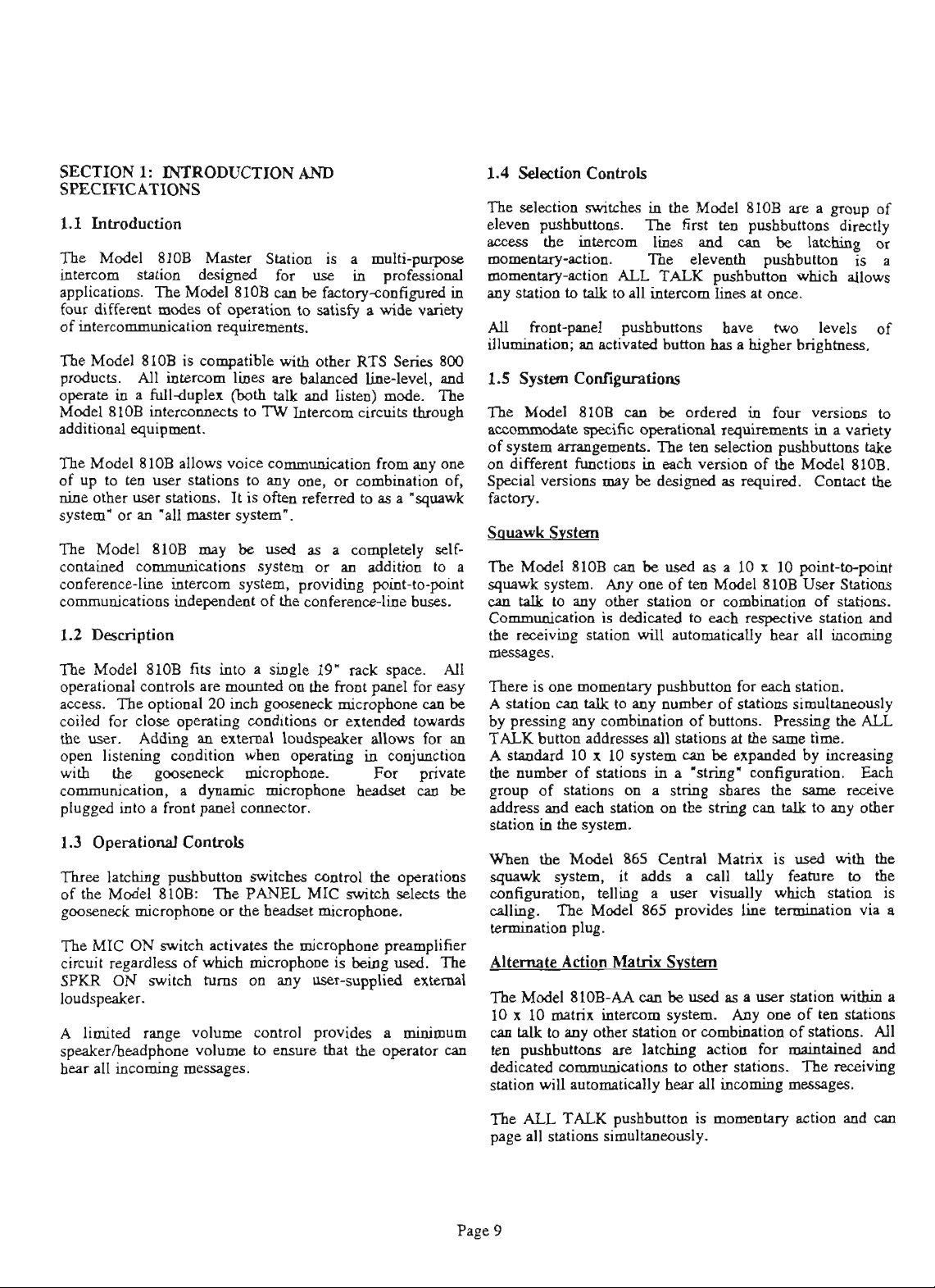
The
Model 810B
intercom station
applications.
different
fouc
of inteM&& req-ts.
The Model 810B
products.
opaPte
Model 810B intermmects to
additional
The Model 810B nllows voice communiclton from my
of
up
nine other
system' or M .all
The
AU
in a fullduplex (both
equipmat.
to ten
user
user
Master
designed
Model 810B
modes
of opesation to
is
compatible
interam
stations to my
stPhOlLP.
master
Station is a
for use in professid
an
be
factoryadigured
satisfy
with
otha
RTS
hes
are
balanced
talk
and
listen)
TW
Intercom circuits
one,
or Wmbination of,
It
is
0th
referred
system'.
to
multi-puqwe
a
wide
variety
Series
hlevel,
mode.
through
as
a
'squawk
1.4 Selection
The
selection
eleven
roess
nmmentqrction. The elevd pushbutton
nmmentq4on
in
mystationtotalktonllintercomlinesatonce.
AU
frontpsnel
illumination; m activated
800
and
1.5
s*
The
The
Model
ConfroIs
swi*
pushbuttas.
the
htercom
in
the Model 810B
The
first
line8
ALL
TALK
pushbuttons
button
ten
pushbuttom
pnd
an
pushbutton
have
has
a higher
are
be
which nllows
two levels of
brightness.
CwTitioD5
8lOB can be ordered in four versions to
a
lntching or
occommodnte@fic~~inaeety
of svstcm MMpemmts.
on kffemt funfunctions in
one
special versions may
l'he
each
be
designed
ten
selection
version of
as
mshbuttons
the
required.
Model 810B.
CoDW
f=W.
group
directly
is
of
a
take
the
The Model 810B may
contained communications system
coaferencbline intercom system, providing point-to-point
communications indepadent of the confereacc-line
1.2
Description
The Model 810B fits
operational controls
~ccess.
coiled for close operating conditions or
the
open listming condition
with
communication, a dynamic microphone
plugged into a front
1.3
Three
of
goosez~~k microphone or the
The
circuit regardless of
SPKR
loudspeaker.
A
speakermeadphone volume to
hear all incoming messages.
The optional20 inch gooseneck minophone
user. Adding
the gooseaeck micqhom.
Operational
latching pushbuttoo
the
Model 810B: The PANEL
MIC ON
ON
limited
ControIs
switch
switch
rnnge volume control provides a
be
used
as
a completely
or
m addition
buses.
into
a single 19"
are
mounted
nn
extemnl
ppnel
actiMtes the microphone preamplifier
which
hms
on the front pel for
lodqedm
whea
opemting in eoojunction
colloector.
switches
head&
microphone
on my user-supplied external
rack
extended
nllows for m
head&
contml
MIC
the operations
switch
microphone.
is
being
space.
For
selects the
used.
can
towards
private
an
minimum
easure
that
the
opator
self-
to
AU
easy
The
can
a
The
Model 810B
squawk
caa
Communication
the
-$es.
There is one
A
be
by pressing my combbation of
systcm. Any
talk
receiving
station
to my
cao
an
be
used
as
a 10 x 10 point-to-point
one
of
ten
Model 810B
other
station
is
dedhted
station
will
momentary
talk
to my number of stations simultaumusly
or
combiion of stations.
to
each
raspective station
automatidy hear
pushbutton
for
buttons.
User
dl
each station.
Mig the
TALKbultoaPddressesnllstntionsatthespmtime.
Astadad
the nnmbe~ of stations
pup
be
10x 10systemcanbeexpmcMby incmshg
in
a
'string'
of stations on a string
urnfiguration. Each
sharea
the
spme
sddreas~eachstationonthestriaganE.ILtomyother
stationinthesystem.
When
tbe
Model
squnwk
dgurotion,
&g.
tenohlion plug.
Altanate
The
system,
TheModel865pmvideslinctembtionvua
Adion
Model 810B-AA
telling a
Central
865
it
adds
Matrix
Svstem
an
10~1OmPtrixintacomsystem.
an
Wk
to
my
other
station
ten
pushbuttons
dedicated communicatim to other
station
will
ua
latching action for
mtomntidy
hear
Mntrix is used
a
CPU
Wy feature
us+r
ViarPlly
be
used
as a user
or
combination of stations.
dl
incoming
which
Anyoneoftenstations
stations.
station
maintpined
The
mssages.
Stations
and
incoming
ALL
receive
with
to
station
within
All
ad
receiving
the
the
is
a
TheALLTALKpushbuttonismomea~taryactionnndcan
page
nll
stations €inlultaumusly.
Page 9
Page 10
latching-action pushbutton
indicating
switch
stPtus
(on or oft).
Tally idmtification is not
Model
865
CeatrPl
Matrix
81OBstatimcanbe~uslngaModel4025A
Splitter.
termination plug.
RTS Systems or
Tm
The
10-Cbanml
pushbuttons
Line
termination must
This
terminntion
nmde
by
the
Channel Conf~ere
Model 810BCL
confereme
are
can
latching
communication on my channel
The
call
tdly feature b not
Ihe810B-cLcanbeusedinavarietyofw~ysWithin
conferw~ce
line
systems.
consists of a single 810BCL cwpled
intercom User Statim.
In-t
is
normslly
used
4012 provides inhwm~&on
the
TW
Inte-rmm User Stations.
pmvides line terminntion for
amtngement
allows
the
81OBCL
TWstationonchannel2mdallTWstatiomcantalkto
each
other on channel
VariaIiom
on system anangemeats
reconfiguring
foaory
Kve
for
more
Channel Conference
1.
and/or
adding equipment. Consult
idomation.
The Model 810ESCIL
conference
latching action
line
inkmom system.
to
allow
continuous
channel or combination of channels.
sepPrnte
wmbiition of
Ihe
Contact
call
talk
tally
the
factory
and
trilling
fealure
listen
and
is not
for
system mg-t.
illuminates
used
in
the
matrix
is
not
negsslry.
be
provided
csn
user
(see
Figure
Line
S'Pstsq
be
used
as
a
use^
line
intearan
action
used
One
to
or
combination of channels.
in
this
example of
The
Model 4012 System
for
this
prpose.
behveen
The
the
to
talk
can
Line
Svh
can
be
used
AU
wdcation on my
pusha
listening
used
in
to
this
when
engaged,
system
be
ordered
by
The
so
Model
a
system
from
3-2D).
station
system.
allow
configuration.
an
within
continuow
mangemeat
With
tea
TW
The Model
the
81OB-CL.
Modal 4012
also
81OBCL. This
directly
easily
within
with
be
made
a
Schmnel
each
pu&buttons
Each
chnnael
this
allows
selected channels.
configuration.
the
a
AU
and
by
the
are
has
my
!hm4
RequiuodMmLiolhapcd.sse:
hlqpltlq4Uwe:
late.MmAndbalowloulpul:
N0mio.l:
l-aopllau)
Uxt
&id.gingimpd.ase: ~obrntomm
-
Transfer
N0mio.l:
Hudrcl
Huda
lnpcauvciluuc:
Headdwae.4md&
Onnu
Inroz5ohmk.d: 9vh@
oulpulParr:
F-Y
HudpbnuIqduxell.npc:
-Am*
la0
kdspe&=R.ogs:
Each
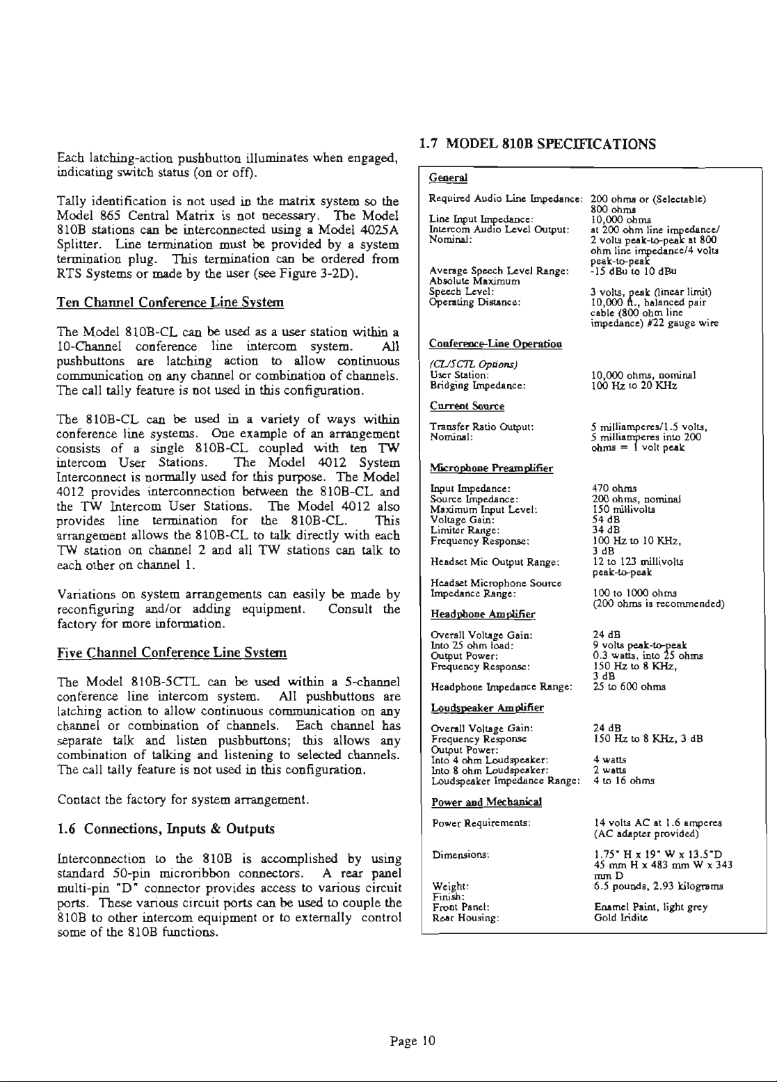
1.7
MODEL
Diaurc:
Sutim:
Ruio
Pram*
Mic
%lpul
Micmphon
Vhp
-:
s
ohm-
810B
SPECIFICATIONS
MoDbrma(SI*stlbk)
800otua
10.000 cbma
3
VOb
10,ood~~
cmb!e@ooobmb
inpcd.oc)N~wlcwirc
10000ohrm,~
anput:
470 cbma
m
150
54 dB
34
lM)IL.u,lOIMz,
3
R.ogs:
Sauce
Win:
dB
12 to 123
pul;w
100to1OOOobrm
(200obrmiS~
24
0.3
ISOlbu,8KHz,
dB
3
25to600obrm
24
15OHzto8KHz.3dB
4wll.
2
wuo
4to 16cbma
dims.
millivolu
dB
dB
wuo,
dB
~rlimii)
p.ir
r.dd
milli&
hTobrm
1.6
Connectioas,
Interconnection
standard
multi-pin
ports.
81OB
mme
SGpin micmribbon
"D'
These
various circuit
to
other
of
the
810B functions.
Inpuk
to
the
810B
&
Outpuk
is
cmnechs.
mector pmvides
ports
intercom equipmeat
accomplished by
A
rear
~ccess
to
various circuit
can
be
used
to
couple
or
to
externally control
using
panel
the
Page 10
~~~
We*: 6.5
Fd:
Fmrn
p.acl:
Btu
H*:
14vobACu1Ia~rsr
(AC
1.75' H x 19- W x 13.5'0
45mmHx483mmWx343
lnmD
-Ria,Gghrwy
Gold
d.p(cr
pormd..
lridii
pmvidcd)
2.93
Lilqnrm
Page 11
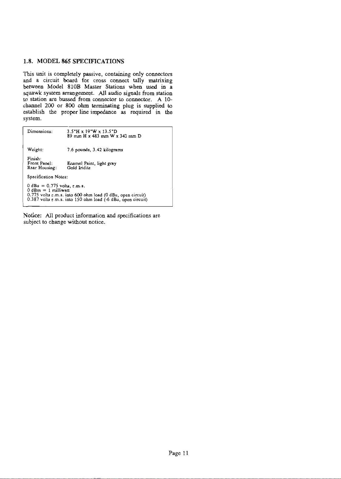
1.8.
MODEL
This
unit
aad
a
circuit
belweu~
squawk
to
channel
system
atation
200
est&Lish
system.
865
SPECIFICATIONS
is
completely
boud
Model
~~t.
are
bussed
or
the
pmperline~~s
810B
800
passive,
for
cross
Mnster
from
conncdor
ohm
tednhg
EontpiniDg
umnect
Stations
AU
do
dy
coMectors
tally
mntrixing
whea
used in
signals
to
plug
fromatation
collasctor. A 10-
is
supplied
required
in
a
to
the
Dime-:
Wcighl:
Pi
FmaRd
ReuHouinp:
Spcsi&
0
dm
-
OdBm-
0.775
0387
Notice:
subject
0.775
voh.
vdu
All
to
NoTu:
v*
1wiUiw.11
r.m.1.
r.m.1.
product
cbange
3J'Bx
7.6
Ooldkidac
+
mto
19W x 13J'D
89nrmHx483mmWx343mmD
pound.,
3.42
Wqntlli
LvmclRilightgsay
t.-.
600
dm
Id
(O
dW,
opcn
150
dm
hud
informption
without
notice.
(-6
and
dm,
cirnii)
apn
&IUI)
specifications
are
Page 12
MODEL 810B
MODEL
865
MODEL 810B
MODEL 8108
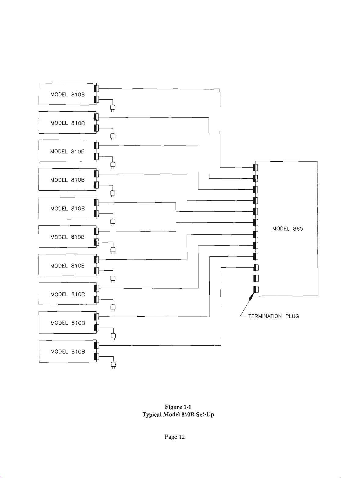
Typical
Figure
Model
Page
1-1
810B
12
Set-Up
TERMINATION
PLUG
Page 13
'
SECIION
This
applies
dguration.
Squpwkcanfiguratim.
2:
sectiw
to
all
INSTALLATION
is
divided
Model
A
standard
into
810B's,
Model
three
parts:
regardl888
810B
of
is
fhctoryaet
the
system
in
the
TheCoafiguxati01lssecti0ndetailsase-upforeachofthe
Model
810B
system
dguratim
Fcstrues
section
Thc
exp~~touseeachofthev.d~~tfeatwesofthe
Model
81OB.
The Model
to
fit in
onerackunitofspace.
allowing plmty of
23
The
810B
mounted
1.6
amps=
or
trausf~mer
used.
of
JlOl
Drawing Rear Panel.) If
positive
the supply
810B
M
EIA
POWER
reqb
power
Attach
on
side
to
is
enclosed within a
stsDdsrd
19.
Seuuelyfastentheunittotherack,
rcmn
in
the
14
volts
AC
module
is
shipped
capable of supplying
the
the
of
the
pin 4 of
with
with
output of
rear
panel.
supply
J101.
the
n
DC
to
each
pin
metal
equipment
back
for
cable
or
18
volts
an output of
unit.
An
this
2
supply
Figure
is
md
the
power
AC
(See
supply
case
nJc
cmmections.
DC.
14
ex&
to
pins
3-2,
used,
negative
desigaed
md
occupy
volts
may
2
Outline
mnaect
wall
A
AC
at
supply
Plso
be
md
the
side
of
3
2.2.1
The
system
those
up
RTS
cable
pir
All
Model
used
to
10,000
sy*,
lea$(h
cable
of
Wm
using
the
and
Cable
810B
is
SO-conductor,
by
the
telephme
feet long.
nfcr
md
type)
(strpnded).
Model
810B
ComiWom
ranntaed
to
(25pir)
company.
These
cables
to
in
Model
flat
4015-XX (-XX
ribbon cable
dgnratim
other
The
are
units
cables,
cables may
available
or
nnmd
nquire
within a
similar
from
refels
twisted
that
to
be
to
the
chsnndsbe~inadertoestablishthecorrect2W
ohm
line
impdwe.
200
ohm
system
number
The
9020-2919-00.
standnrd
Intexcodcatiw
ex+mslly loag cable
This
temidw
liue
impsdPnce
System
is normally
See
Figwe
sums
plug.
is
are
accomplished
RTS
26A.
for
the
200
ohms.
used,
or
Systems
Model
when
with a
part
8lOB
whea
M
8W
ohmlinc~isdcsirrd,an8U)ohm~on
plug is^.
Systems.
Canfully
lwmiguratiw
mpimmsnts
cuefully
using
a
needed
in-tion.
ThispartmsybeordenddirectlyfromRTS
The
part
check
to
Model
since
numba is
the
to
and
location.
avoid any
4012
in
the
4012
detemh
itldhtim
hmhatiw
the
system,
provides
9020-2919-01.
section
termination
Follow the instructions
problems.
a
temhtion
mmhtion
w
each
plug
NOTE:
plug
is
as
well
If
not
pr
Page
13
Page 14
SECTION
3:
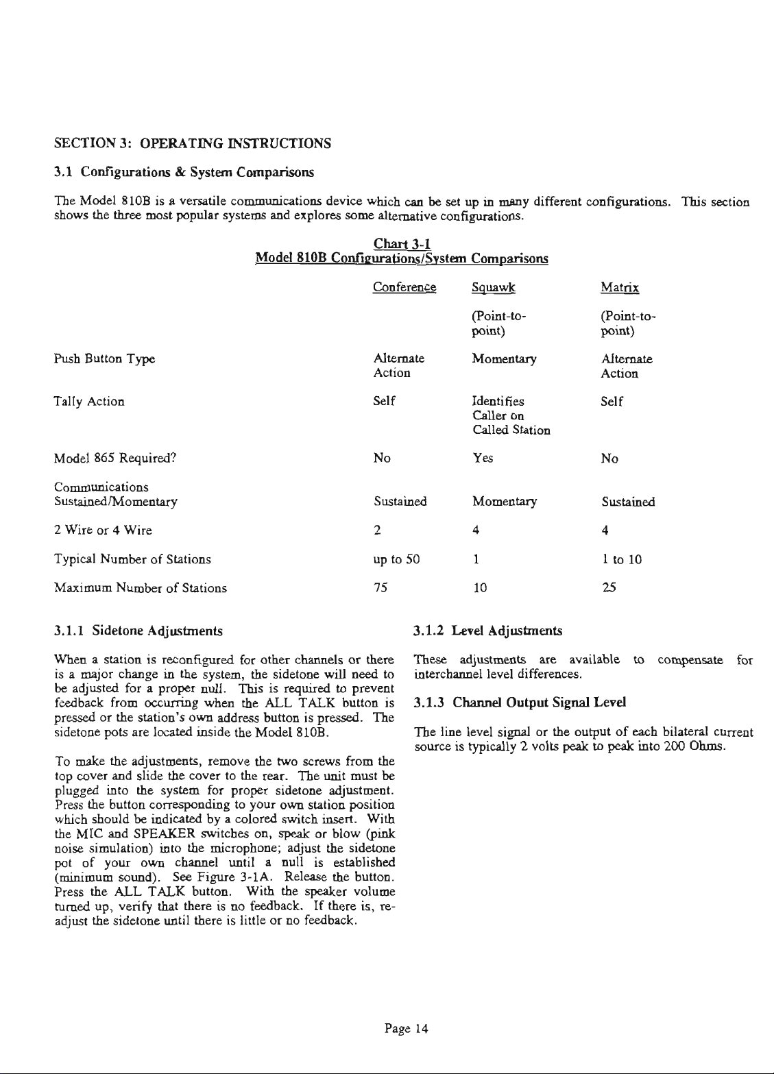
OPERATING INSIRUCTIONS
Codimtions
3.1
The
Model
shows
the
three
Puss
Button
Tally Action
Model
865
2
Wue
or 4 Wire
Typical
Number
&
810B
is
a
versatile codcations
most
popular
Type
Requirsd?
of Stations
System
systems
Compprisolg
and
explores
Model
SlOB
device
which
cat
be
som
alternative
Codiivstcm C-
Attenlate
Action Action
set
up
in mrny
contiguratioas.
M-tPry
Idmtifies
on
wer
Called
Station
different
d@ons.
(Point-to-
point)
Attenlate
self
This section
Maximum
3.1.1 Sidetone AGustments
When
is
a
be adjusted
feedbackfromoccvringwhentheALLTALKbuttonis
pRssedortheststion'sownPddnssbuttonisprrssed.
sidetone pots
To
top cover
plugged into
Preas
which
the MIC
noise simulation) into
pot
(minimum
Press
turned
adjust
Numter
a
station
major chauge in
for
make
the adjustments, remove the
and
the button
should
and
of your own cbl
sod).
the
ALL
up,
verify
the
sidetone
of Stations
is
rocODfigured
the
a
pruper
am
locPUd
slide
the
the
system for
fonsspwding
be
indicated
SPEAKER
See
TALK
that
until
system,
null.
inside
cover to the
by a colored
switches
the
mimophone;
Figure
button. With
there
is
there
for other
the
This
the
proper
to your own ststion position
until
3-1A
no
fedback.
is
little
cham&
sidekae
is
rquired
Model
two
rear.
sidemm
810B.
scrsws
The
switch
on,
speak
or blow
adjupt
a
null
is
Relase
the
speaker
If
or no feedback.
or
will
need
to
preveat
from
uuit
must
djustmmt.
insert.
the
aidezone
established
the
button.
volume
there
is,
thcn
With
(pink
3.1.2
Theae
interchPnnel
to
3.1.3
'Ihc
l'be
source
the
be
re-
Level
Adjustme&
adjustmmts
level
are
available to
differences.
ChnaaelOutputSjgnnlLevd
line
level signal or
is
typically 2 volts
the
peak
output
to
of
peak
compmsDte
each
bilateral
into
200
for
cumat
Ohms.
Page
14
Page 15
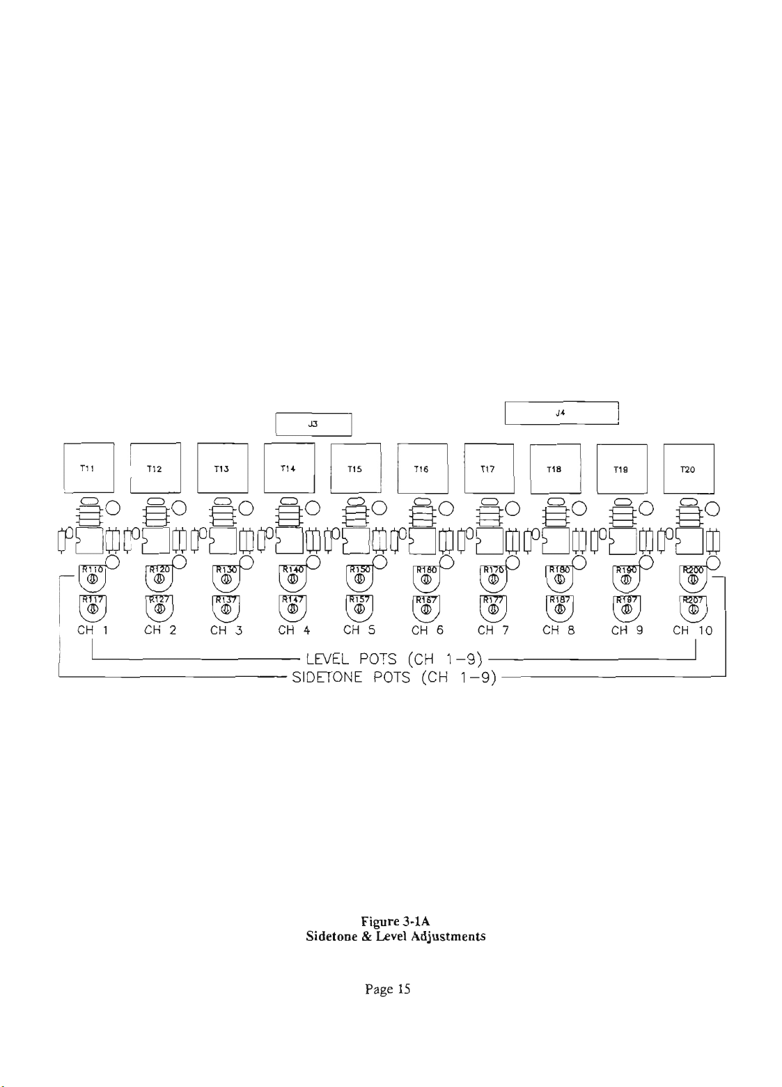
L
LEVEL
Sidetone
POTS
Figure
&
Level
Page
(CH
1-9)
3-1A
Adjustments
15
Page 16
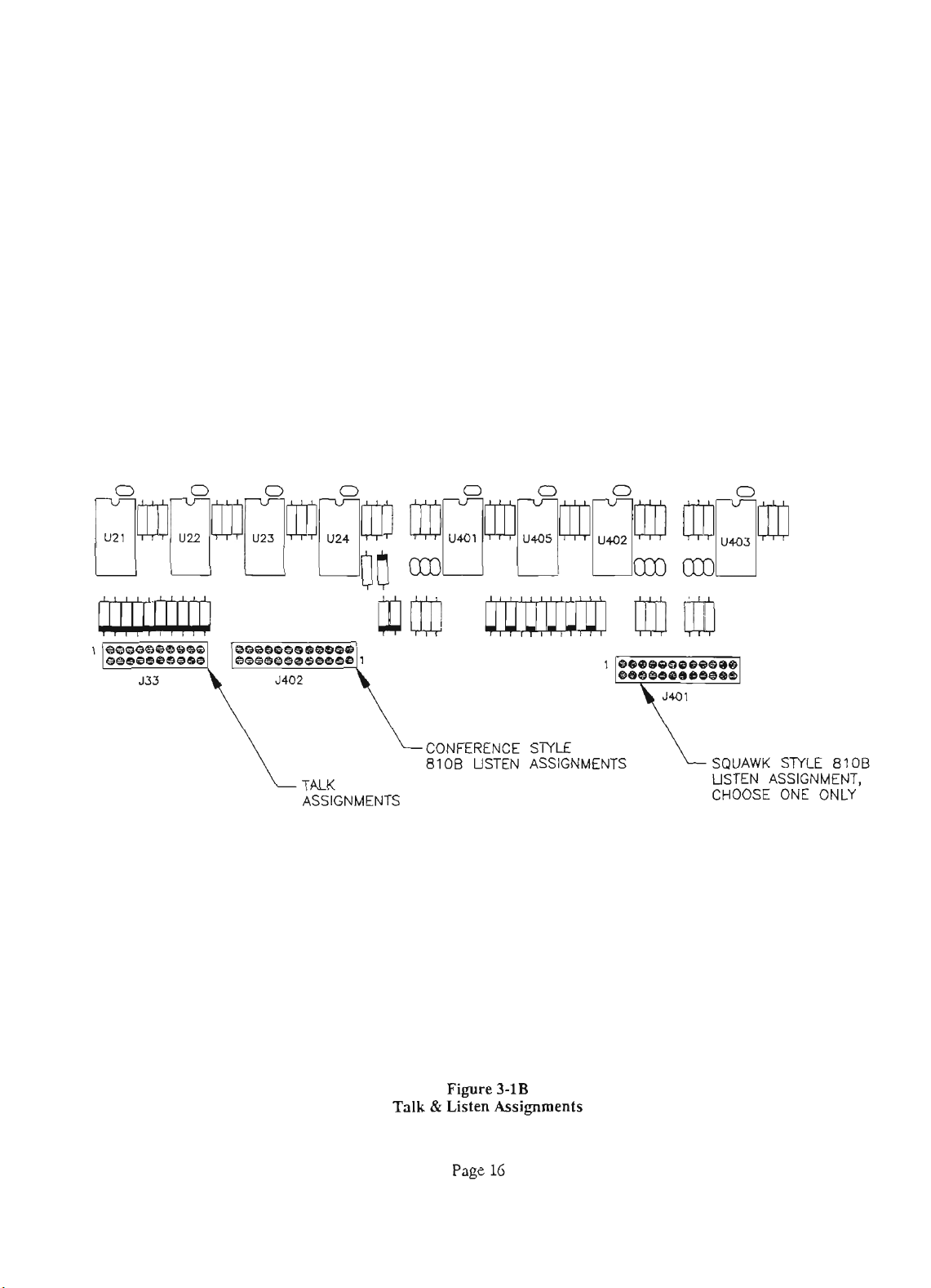
/-
LCONFERENCE
Tu
ASSIGNMENTS
8100 USTEN ASSIGNMENE
STYLE
USTEN ASSIGNMENT,
CHOOSE ONE ONLY
Talk
Fii
&
Listen
Page
16
3-1B
Assignments
Page 17
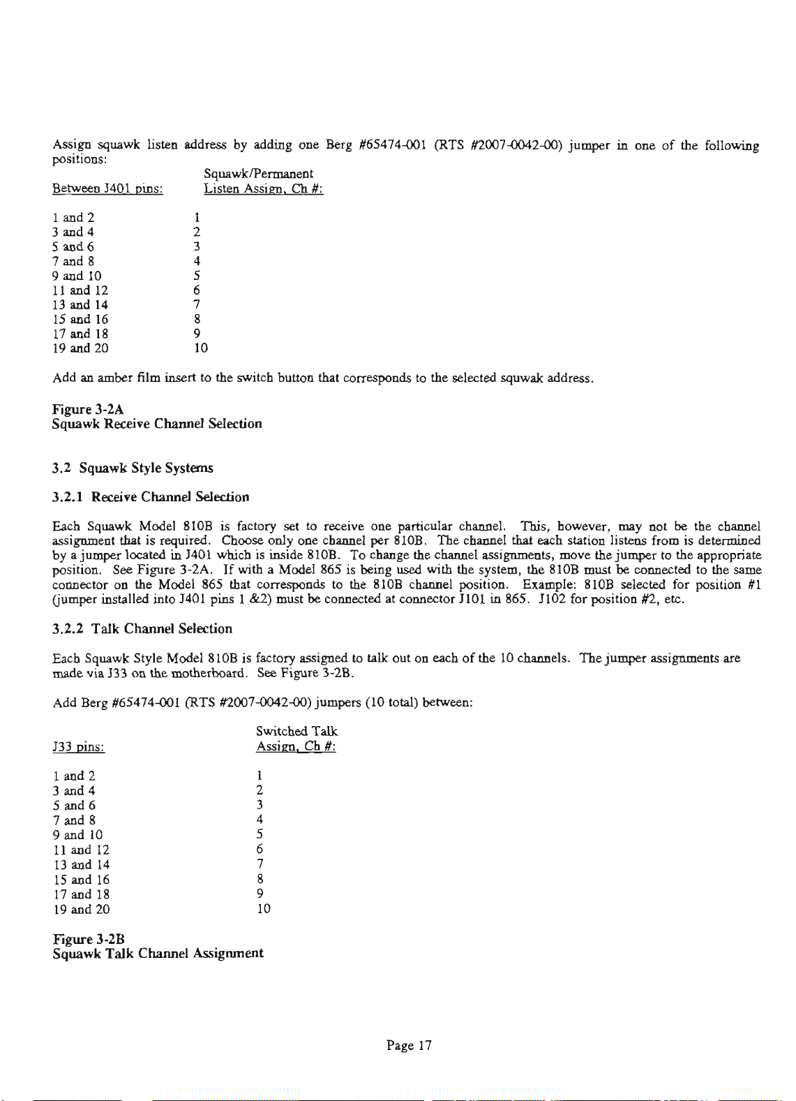
Assip
positions:
Behveen I401
Add
m
squawk
amber
listen
~ias:
film
address
inse.rt
sqlla-t
Listen
to
the
by
adding
Assism.
switch
one
Ch
#:
button
that
Berg
fi5474-001
compds
to
(RTS
the
selected
#2WM)42M))
squwak addma.
jumper
in
one of Ihe following
Fi
Squawk Receive
3.2
3.2.1
Each
assipmatthstisrequirrd.
byajumperlocatsdinJ401whichisinside810B.
position.
connector
(jumper
3.2.2
Each
mPde
Add
$33
3d4 2
5md6 3
7md8 4
9
3-2A
CChsna
Squawk Style
Rcaive
Squawk
See
on
iastalled
Talk
Squawk
via
133
Berg
fi5474-001
~ias:
lmd2
and 10 5
11
dl2 6
d
13
15
17 aud 18
19
14 7
d
16 8
d
20 10
Systems
Chnnael
Model
Figun:
the
Model
into J401
Channel
Style
on
the
Selection
Selection
SlOB
is
Ch00seonlyomohsrmelper81OB.
3-ZA.
865
If
that
pins
Selection
Model
810B
motkhad
(RTS
#2WM)42M))
factory
set
with
a
Model
correspondP
1
&2)
must
is
factory
See
Figure
Switched
Assim.
1
9
to
dve one
865
to
be
connected
assipd
3-2B.
jnmpers
Talk
Ch
#:
perti&
Tochangethcchmnelassi~ts,m~vethejumpertothesppropriate
is
being
used
the
810B
at
cmuector
to
tnlL
out on
(10 total)
chaunel.
This,
however,
may
not
be
the
ohsrmel
ThechPnndthateachstPtionlisteasfromisdetermined
with the
channel
each
betweex
system,
position. Exnmple:
JlOl
of
the
the
in
865. JIM
10
clunnels.
8lOB
must
8lOB
for
The
be
selected
position
jumper
connected
#2,
to
for position
etc.
assignments
the
slm
XI
are
Fi
Squawk
3-2B
Talk
CChsna
Assignment
Page
17
Page 18
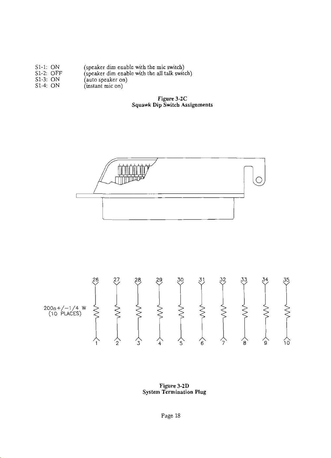
S1-1: ON
S1-2:
OFF
(speaker
(speaker
(auto
(it
dim
dim
speaker
mic
enable
enable
on)
on)
with
the
with
the
Squawk
mic
all
Figure
Dip
switch)
talk
switch)
3-2C
Switch
Assignments
System
Figure
3-ZD
Termination
Page
18
Plug
Page 19
MODEL 8108
u
MODEL 8108
IL
u
MODEL 8108
MODEL
4027
50
/,
50
/
I
I
MODEL 8108
STRING
MODEL 8108
MODEL 810B
nb
I
MODEL 810B
MODEL 8108
I
MODEL 865
I
[
L
4-1
2
MODEL
4027
TWO TYPICAL STRINGS SHOWN;
UP
TO
TEN
STRINGS POSSIBLE.
TERMINATION PLUG
1
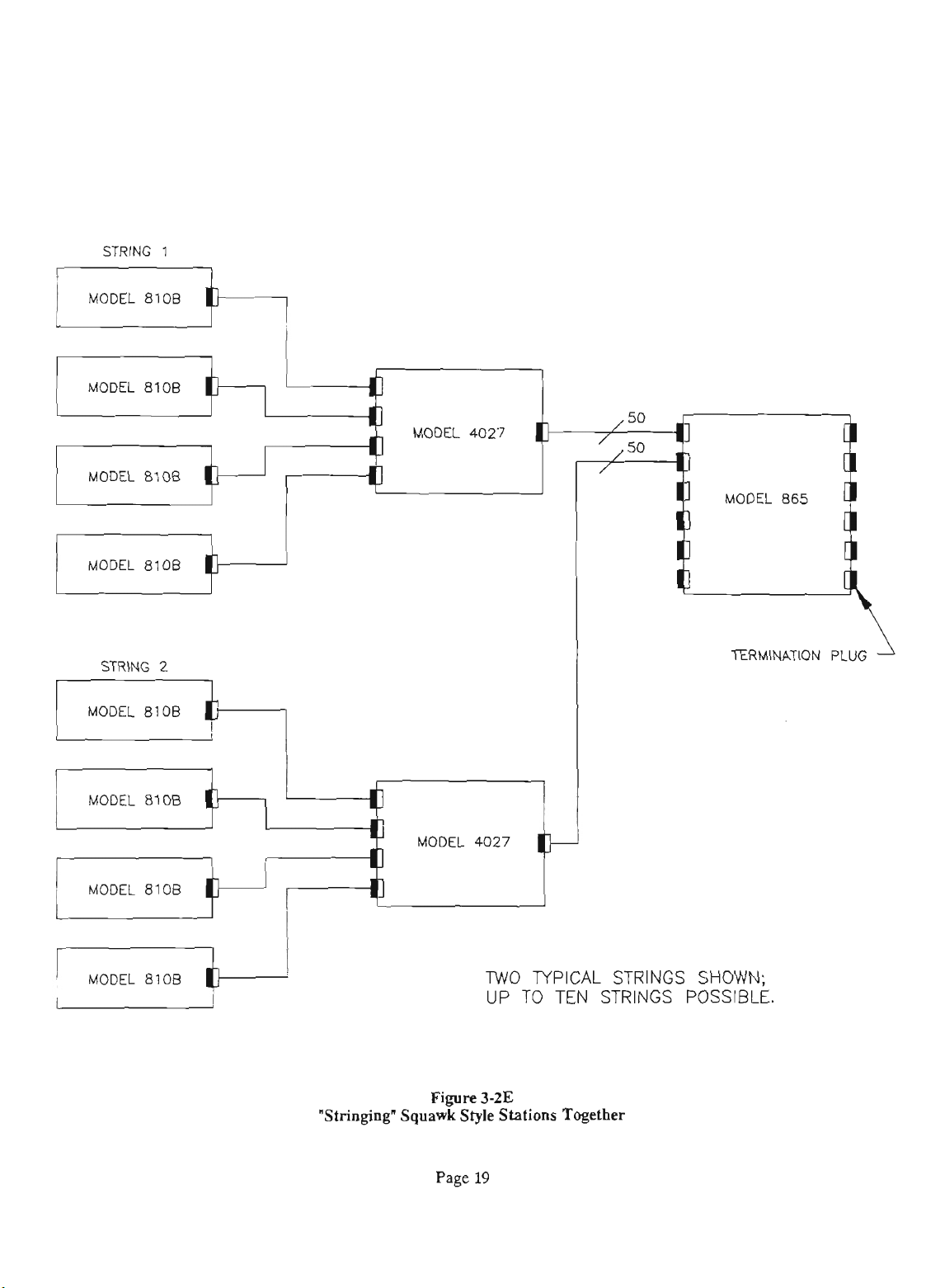
"Stringing'
Fire
Squawk
Page
3-2E
Style
19
Stations
Together
Page 20
33.3
Dip
Switcb
Asigumenta
33.4
"Shkghg"
Squawk
Worn
Together
In a squawk
The
speaker
switchismnbled.
fa
-1SdB.
the
810B
carbled~the81OB~serpushesona"STA'(orsqunwL
cbnnnel)
3.2.5
style
dim
lk
auto
dves a call.
buttm.
Squawk
Systan
810B,
cedu
fuuction
is
logic
active
functions
when
the
am
uSed
MIC ON
Thcspeakerdimpot(R85)isfPctorysct
speaker
See
Figure
on
fuaction
The
instant
3-2C.
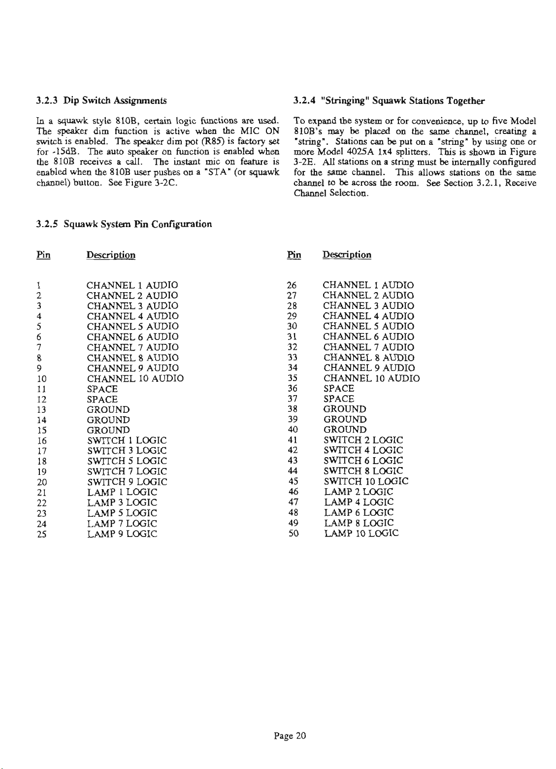
Pin
Confiim
is
mic
carbled
on
feature
whea
To
810B's
'string'.
ma
is
3-2E.
fort he same^.
chnnnel
cbaauol
CHANNEL 1 AUDIO
CHANNEL
CHANNEL
CHANNEL
CHANNn
CHANNEL
CHANNEL
-
--
-
CHANNEL
CKANNU
CHANNEL
2
AUDIO
3
AUDIO
4
AUDIO
~
-.----
5
AUDIO
6
AUDIO
7
--
AUDIO
.
.
-
8
AUDIO
9
AUDIO
10
AUDIO
-
-
-
-
SPACE
SPACE
GROUND
GROUND
GROUND
SWITCH
SWITCH
SWITCH
SWITCH
SWITCH
LAMP
1
LOGIC
3
LOGIC
5
LOGIC
7
LOGIC
9
LOGIC
1
LOGIC
LAMP3UX;Ic
LAMP 5 LOGIC
LAMP
LAMP
7
LOGIC
9
LOGIC
ex&
rimy
tbs
system
be
pl.oed
a
for
on
convsaimcs,
the
spme
channel,
up
Statiu~~ca~beputma'grins'byusingoneor
Model
4M5A
AU
stations
to
be
Sslection.
on
acmes
1x4
splitters.
a
string
'Ihisallowsstati0118onthe~
tht
mom.
must
Sce
This
is
be
interrlly
Section
shown
3.2.1,
CHANNEL 1 AUDIO
CHANNEL
CHANNU
CHANNEL
CHANNEL
CHANNEL
2
AUDIO
4
AUDIO
5
AUDIO
9
AUDIO
10
AUDIO
SPACE
SPACE
GROUND
GROUND
GROUND
SWITCH
SWITCH
SWITCH 6 LOGIC
SWITCH
SWITCH
LAMP
LAMP
LAMP
LAMP8UXiIC
LAMP
2
LOGIC
4
8
10
2
LOGIC
4
LOGIC
6
LOGIC
10
LOGIC
LoGIc
LOGIC
LOGIC
to
five
Model
crdq
in
Figure
configured
Receive
a
Page 21
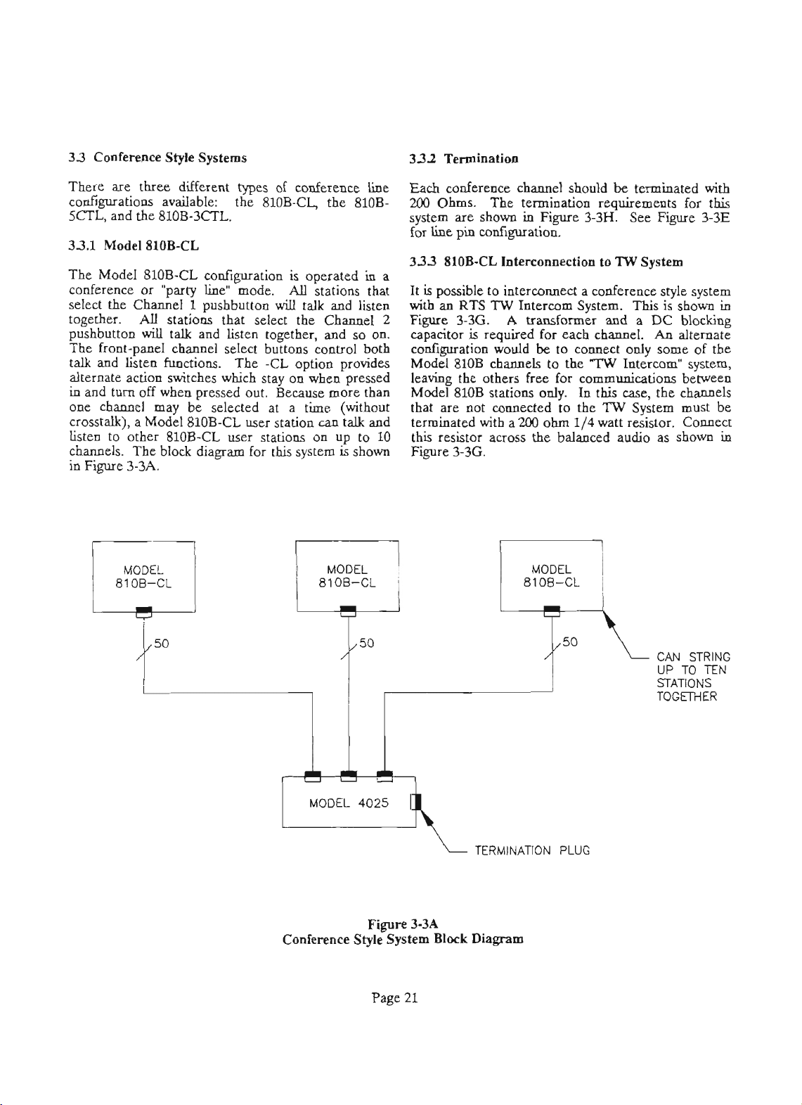
33
Conferena Styk Systems
three
There are
different
wnfigurations available: the
SCl'L,
33.1
and the 810B-3CTL.
Model
81OB-CL
The Model 810B-CL w-tion
wnference or 'party line" mode.
select the Channel
together.
pushbutton
AU
will
1
stations that select the
talk
The front-panel channel select buttons control
talk and listen functions. The
types
of wnference line
810B-Q, the 810B-
is
operated
AU
pushbutton
stations that
will
talk and listen
Channel
and listen together, and so
-CL
option prow
in
on.
both
alternate action switches wbich stay on when pressed
in
and
turn
off when prd out.
one channel
may
crosstalk), a Model
listen to other
channels.
in
Fie
810B-CL user stations on up to 10
The
block diagram for
3-3A.
be
sekcted at a time (without
810B-CL user station
Because
this
system
more
can
than
talk and
is
shown
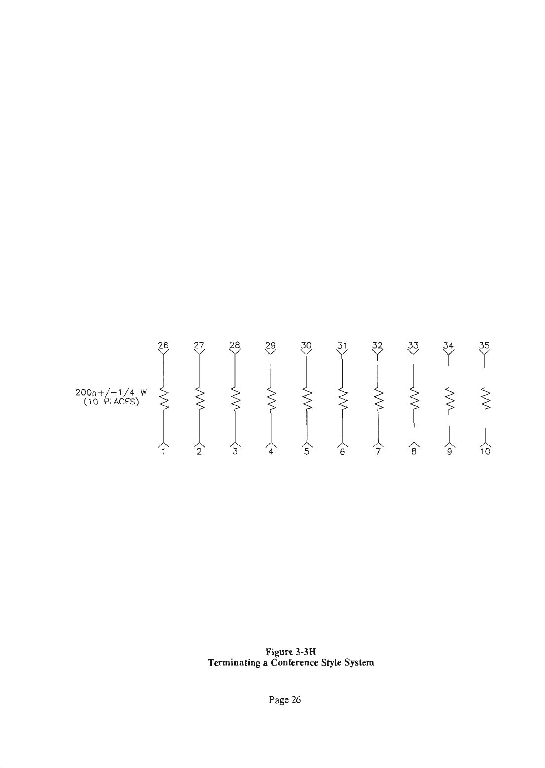
Each conference channel should
be
terminated with
200 Ohms. The termination requirements for
system are show
for
line
pin
wdipatim
333
SlOB-cL
in
Figure
3-3H.
Intereomection
See Fie
to
m'
a
It
is
poshible to interwnnect a wnference style system
with
2
Figure
capaator
configuration would
Model
an RTS
leaY
Mode
that
are
terminated with
this
resistor aaoss the balanced audio
Fie
TW
Intercom System.
3-33.
810B
the others
810B
A
is
required for
chanuek
stations
transformer and a
each
be
to
to
free
for communications between
only.
not conneded to the
a
2W
ohm
>Xi.
chauael.
umuec!
the
"IW
In
this
114
watt
This
only some of the
Intercom" system,
case,
TW
System must
resistor.
system
is
shown
DC
blocking
An
alternate
the channels
Connea
as
shown
this
3-3E
in
be
in
MODEL
81 00-CL
I
U
,50
/
.
MODEL
81 OB-CL
I
/
50
/
I--
U
U
U
MODEL 4025
Fire
3-3A
Conference Style System
Block
MODEL
81 OB-CL
TERMINATION
Dbgmo
I
U
/
/50
PLUG
CAN
STRING
UP
TO TEN
STATIONS
TOGEMER
Page 22
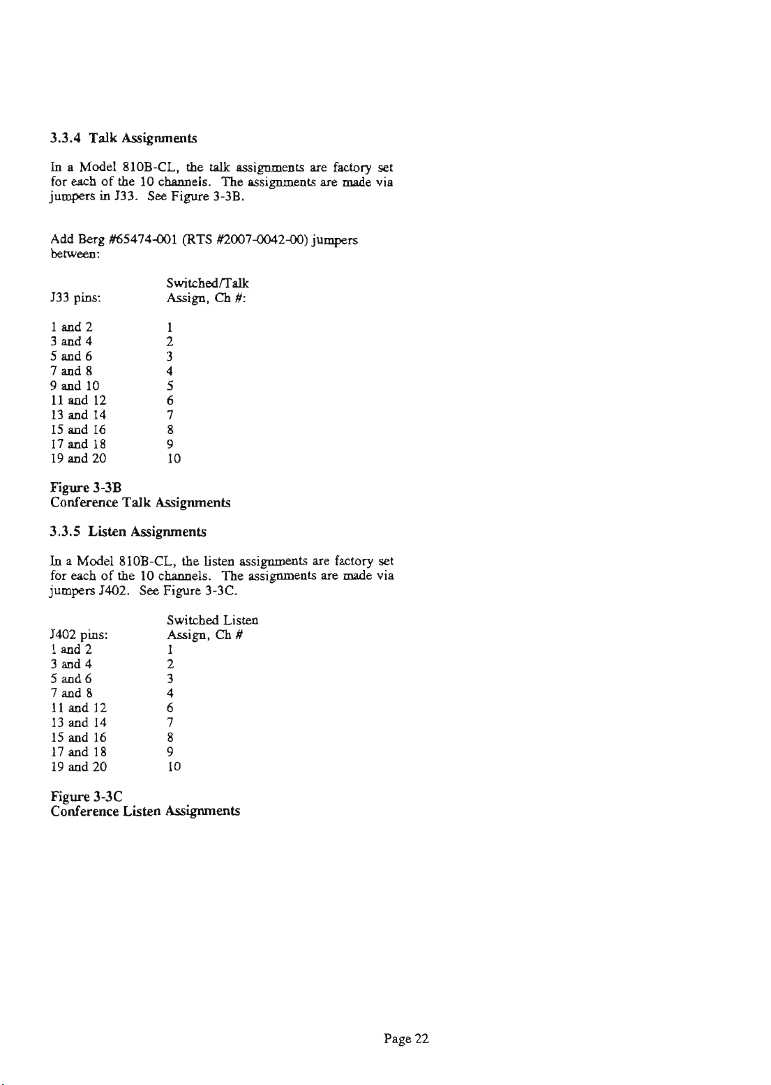
3.3.4
Talk
Assignments
In
a
Model
foreachofthe
jumpers
Add
Berg
btwuK
810B-CL.
locham&.
in
J33.
RX5474.001
the
See
Figure 3-3B.
(RTS
talk
.88ignmz&
Thesssignmeptsaremadevia
m007-004240)
are
factory
jumpen
set
Figure
Conf-
3.3.5
3-3B
Listen
In a Model
for
each
of
jumpers
1402
Id2
3d4
5d6
7md8
11
13
15
17
19
Figure
Conference
pins:
and
and
d
d
and
J402.
12
14
16
18
20
3-3C
Talk
Assignments
ILsigmmb
810B-CL.
the
10
channels.
See
Figure 3-3C.
Listen
Assipnab
the
Lisren
assimts
llie
pssignmenrs
are
factory
are
made
set
via
Page 23
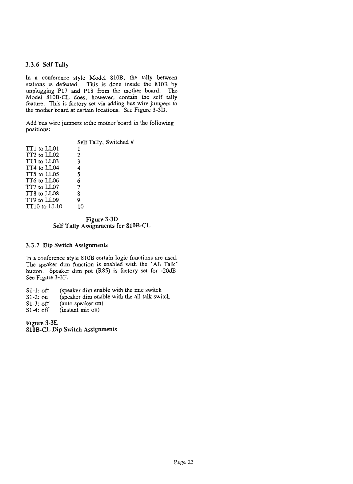
Ia
a
&ce
stations
unplugging
Modcl
feature.
the
Ada
is
810B-CL
Tbisisf.ctorysetvkaddiagbuswirejumpersto
mother
bus
wire
psitions:
style Model
defeated.
This
P17 d PI8
does,
bod
a!
certnin
jumpers
totbe
810B.
is
done
from
however,
loutions.
mother
the
wntaia
board
the
tally
inside
mother
the
See
Figure 3-3D.
in
the
between
the
810B
bod.
self
following
by
Tbp
tally
I
3.3.7
Dip
In
a
de- style
The
speaker
button.
See
sl-1:
si-2:
si-3:
Spdw
Fip 3-3F.
off
oa
off (auto
S14off
Figwe
81OB-CL
3-33
Dip
Fm
Self
Tally
Asignmeats
Switch
Assignments
810B
dim
function
dim
pot
(speaker
(speaket
dim
dim
speaker
(inicon)
Switch
Assiients
3-3D
certain
is
enabled
(R8.5)
euable
eaable
on)
for 810B-CL
logic
functions
with
is
factory
with
the
mic
with
the
Pll
the
set
switch
talk
are
"All
for
switch
used.
Talk'
-2OdB.
Page
23
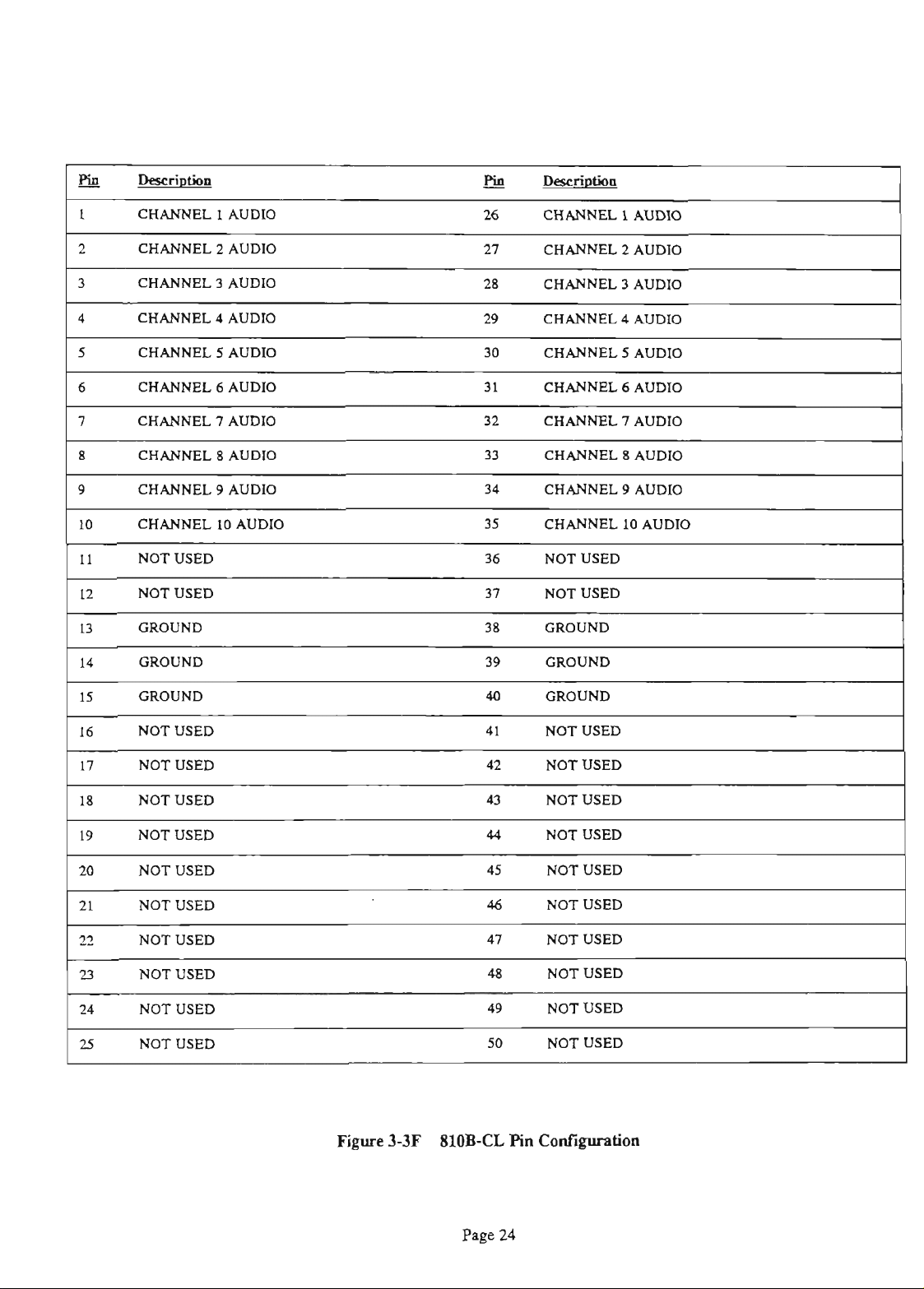
Page 24
rill
ti!!
1
2
3
4
5
6
7
8
9
10
11
12
13
14
CHANNEL 1 AUDIO
CHANNEL
2
AUDIO
CHANNEL 3 AUDIO
CHANNEL 4 AUDIO
CHANNEL 5 AUDIO
CHANNEL 6 AUDIO
CHANNEL 7 AUDIO
CHANNEL 8 AUDIO
CHANNEL 9 AUDIO
CHANNEL
10
AUDIO
NOT USED
NOT USED
GROUND
GROUND
26
n
28
29
30
31
32
33
34
35
36
37
38
39
CHANNEL 1 AUDIO
CHANNEL
2 AUDIO
CHANNEL 3 AUDIO
CHANNEL 4 AUDIO
CHANNEL 5 AUDIO
CHANNEL 6 AUDIO
CHANNEL 7 AUDIO
CHANNEL 8 AUDIO
CHANNEL 9 AUDIO
CHANNEL
10
AUDIO
NOT USED
NOT USED
GROUND
GROUND
15
16
17
18
19
20
21
22
21
24
P
25
GROUND
NOT USED
NOT USED
NOT USED
NOT USED
NOT USED
NOT USED
NOT USED
NOT USED
NOT USED
NOT USED
40
41
42
43
44
45
46
47
48
49
50
GROUND
NOT USED
NOT USED
NOT USED
NOT USED
NOT USED
NOT USED
NOT USED
NOT USED
NOT USED
-
NOT USED
Page 25
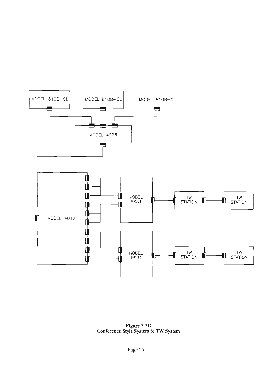
MODEL 81 00-CL
I
7
MODEL 8100-CL
I
&Ia
-
MODEL 4025
I
MODEL 81 00-CL
'r'
[I
MODEL
PS31
[I
I
T
lw
STATION
I
lw
STATION
I
MODEL 401
2
[
[
Conference
[I
MODEL
I
PS31
Fi
Styk System
Page
3-36
25
to
'IOY
System
TW
STATION
I
lw
STATION
Page 26
111111~3~3~313
200n+/-1/4
(10
PLACES)
W
1
2
3
Terminating
4
Fim
a
Conference Style System
5
3-3H
6
7
8
9
10
page
26
Page 27
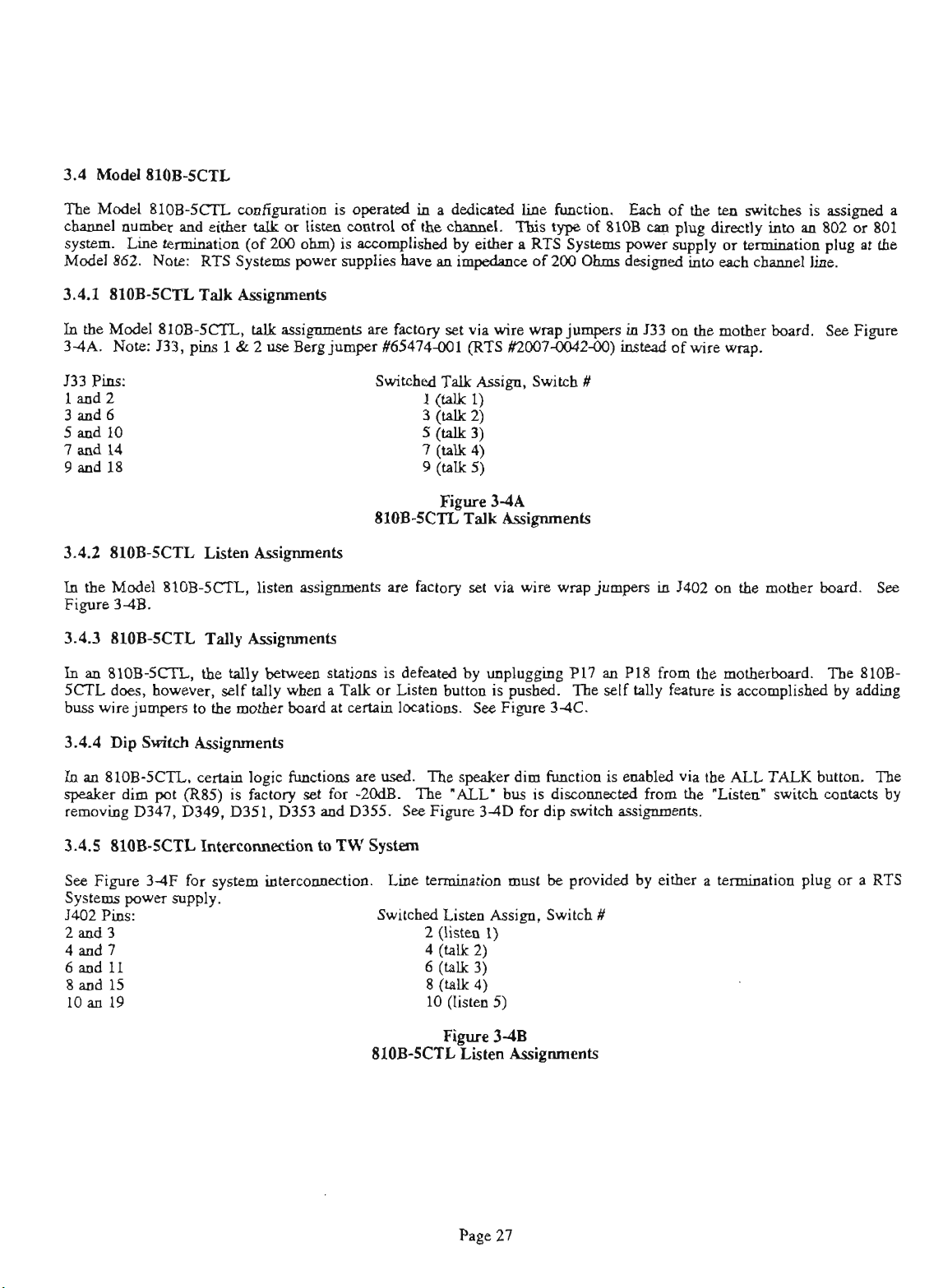
3.4 Model 810BSCTL
The
Model
chPDnel
system.
Model
SIOB-SCTL
number
~i~e
862.
and
tumid011
Note:
RTS
either
cmfiguratim
tdk
or
listea
(of200 ohm)
System
power
is
opfmted
control
is
vlishcd
supplies
in
of
the
have
a
dedicated
cbmukel.
by
ak
an
impahme
line
This
tyDe
a
RTS
of 200
function,
of
810B
3ystems
Ohms
Each
of
an
power
designed
plw
&-ly
the
tea
MY
into
each
switches
or
&mination
chamel
into
is
an
line.
assigned
802
or
plug
801
at
a
the
3.4.1 81OESCIZ
In
the
34A.
J33
Pins:
1
and2
Model
Note:
810B-5Cn,
133,
3d6
5d10
I
and
14
9
d
18
3.4.2 810ESCTL
In
the
Model
81OB-SCn,
Figure 34B.
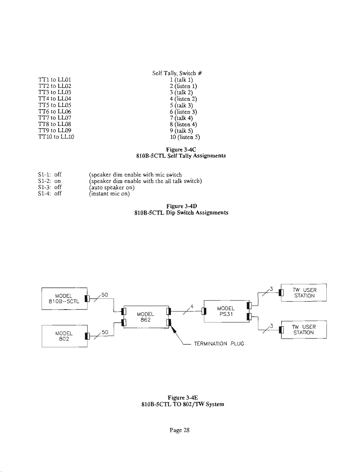
3.4.3 810ESCTL
In
an 81OB-SCTL,
5CTL
does,
however,
buss
wire
jumpers
3.4.4 Dip
Switch
Talk
pias
1 & 2
Listen
Tdy
the
self Uly
to
the
&ipm&
&ipments
talk
assignmats
use
&rg
A&p~ents
li&a~
nssignmeuts
Assignmenb
tolly
between
wha
mother
board
pn
jumper
stations
a
Talk
at
eettpin
factory
W74-001
Switched
1
(U
3
(u
5
(a
(a
7
9w5)
arc
factory
is
defeated
or
Listen
locations.
set
via
wire
(RTS
Tdk
Assign,
1)
2)
3)
4)
set
via
by uapluggiog
button
See
is
Figure
wrap
jumpas in
1Y2007-2M))
Switch
wire
wrap
pushed.
34C.
133
instad
#
jumpers in
P17 an PI8
The
self
tdly feahlre
on
of
J402
from
(hs
mother
wire
wq.
on
the
the
motherboPrd.
is
pccompbhd
board.
mother
Sa
Figure
board.
Tbe
810B-
by Pdding
See
In
an 810B-5Cn,
speaker
removing
dim
D347, D349, D351, D353
3.4.5 810B-SCTL
See
Figure 3-4F
Systems
J402
power
Pins:
ceNia
pot
(RSS)
Intgcodm
for
supply.
is
system
logic
iimctiom
factory
set
for
and
to
intermnmction.
are
-20dB.
D355.
TW
used.
The
See
System
Line
Switched
The qdcer
'ALL*
Figure 3-4D
kzmktion
Listen
2d3 2(listm1)
4 and 7
6andl1
8
and 15
10 an 19
810BSCIZ
(u
4
6
(w
8
(a
10
@istea
Figure
Li
Page
2)
3)
4)
dim
function
bus
is
~rmected
for dip
must
be
Assign,
Switch
5)
3dB
Assignments
27
is
enabled
switch
Pssipm~~ts.
provided by
#
from
either
via
the
ALL
the
'Li'
a
termiaation plug or
TALK
switch
buturn.
contacts
a
The
by
RTS
Page 28
Self
Tallv.
liidk
2
(listen 1)
3
ftalk2)
7 (talk
8
(listen 4)
g(talk-9
10 (listen
Switch
1)
4)'
#
5)
S1-1: off
on
S1-2:
S1-3: off
S1-4: off
MODEL
81 00-5CTL
MODEL
802
(speaker
(speaker
auto
speaker on)
/
50
/
,50
/
dim
enable with
dim
enable
810B-5CTL
mic
with
the
810E5CIZ
MODEL
862
Flgu-W
SeUTally
switch
all
talk
switch)
Figare
Dip
34D
Shtcb
Assignments
Assignments
I
MODEL
PS31
TERMINATION
PLUG
NV
USER
STATION
TW
USER
STATION
Figure
810B-SCTL
3-4E
TO
SOZ/lW
System
Page 29

Danic4bq
Pin
mrxwm
1
2
3
4
5
6
7
8
9
10
11
12-
13
14
CHANNEL 1 AUDIO
CHANNEL 2 AUDIO
CHANNEL 3 AUDIO
CHANNEL 4 AUDIO
CHANNEL 5 AUDXO
CHANNEL 6 AUDIO
NOT USED
NOT USED
NOT USED
NOT USED
NOT USED
NOT USED
GROUND
GROUND
26
27
28
29
30
31
32
33
34
35
36
37
38
39
CHANNEL 1 AUDIO
CHANNEL 2 AUDIO
CHANNEL 3 AUDIO
CHANNEL 4 AUDIO
CHANNEL 5 AUDIO
CHANNEL
6
AUDIO
NOT USED
NOT USED
NOT USED
NOT USED
NOT USED
NOT USED
GROUND
GROW
15
16
17
18
19
20
21
22
23
24
25
GROUND
NOT USED
NOT USED
NOT USED
NOT USED
NOT USED
NOT USED
NOT USED
NOT USED
NOT USED
NOT USED
Model
40
41
42
43
44
45
46
47
48
49
50
Fm
810ESCTL
GROUND
NOT USED
NOT USED
NOT USED
NOT USED
NOT USED
NOT USED
NOT USED
NOT USED
NOT USED
NOT USED
3-4F
Pin
Contiition
Page
29
Page 30

35
Matrix
System
Configuration
(81OB-AA)
The matrix intercom system
Matrix-configured user stations have alternate
station or sct of stations and
does not have tally lighting.
cm6guration for the Matrix Con6guration
is
interconnected
speak
without
Each
station
using
action
having
is
dedicated to a different channel.
to hold the buttons
is
the
same
termination plug into a connector location on the Model
Model
Switch
as
4M5A
4MSA
(-AA
the
Squawk
splitters
or
option)
down
as
4027
splitters
allowing
while
talking.
See
Section
Ontigration.
shown.
as
shown
in Fwe
users to punch
This
type
3.1.
The
Insert
up
of system
JIM
pin-out
the system
S5.
a
Matrix
Figure34
System
Page
Block
30
Dim
Page 31

3.5.1 810B-AA
Talk
higments
Thc8lOEAAtslLsssi~t9mfoctorysetfordofthelQ~.
the
mother
J33
pins:
142 1
3md4 2
546
7md8 4
9 md 10 5
11 md 12 6
13 md 14 7
15 md 16 8
17 md 18 9
19 md 20 10
The
per
unit.
in
one
Betweea
142
3d4
5d6
7ad8
9
and
11d 12
13
and
15
and 16
17
d
and 20
19
bod.
HOB-AA
!%e
of
the
1401
10
14
18
See
listea
Figure
following
pins:
Figure 3-5A.
assignmat
3-5B.
Assign
positions:
is
Add
made
squawk
Berg
6W474-001
Switched Talk,
8loB-'4.4
via
a
jumper
hitea
--t,
3
Fw
Talk
in
J401
.ddre9s
1
2
3
(RTS
X20074042M))
Assign,
3-5A
haipuentp
on
the
by
adding
Listen
Th..sSi~tsmmsdeviajumpersinJ33on
Ch
#
mother
one
board.
Berg
K5474-001
Assign.
jumpers
Oaly
#
(10
total)
bawcm
one cbnnnel should
(RTS
#UXnM)42-OD) jumper
be
selected
8lOB-AA
Fi
3-5B
Listen
Assigameat
Page 32

3.5.3 8lOB-AA
In
a
mahix
810B-M, however,
total) to
the
Tally
style
81OB-M , the
mother
bsipwats
will
board
self
in
tally
tally
the
following
betweeu
when
a
positions:
sfations
chaaael
Self
Tally,
is
defeated
button
Switch
1
is
pushed
rY
by
unplugging
on.
See
Figure
P17
.nd
3-512.
PI8
from
Add
the
Bus
mother
wire
bcd.
jumpers
The
(10
3.5.4 810BAA
In
the
HOB-AA,
active.
S1-1:
S1-2:
S1-3:
S14
The
off
on
off
off
Dip
speaker
Switch
fatnin
dim
(speaker
(sperlrer
(itmt
Assignments
logic
functions
pot
(RW)
dim
dle
dim
dle
on)
mic
on)
is
factory
810BM
pre
used.
set
with
the
with
the
SlOB-M
for
mic
all
The
-2MB.
talk
Fi
3-5C
Tally
Assignments
speeker
See
witch)
switch)
Fi
Dip
3-5D
switch
dim
feaIure
figure
3-5D
Assignments
is
for
enabled
dip
switch
when
the
ALL
Pssi~tp.
TALK
button
is
Page 33

3.6
Combinations
Systems
3.7
8108
Features
The Model
810B
is
designed
so
users
have
the option
Each
of combining several elements of a system to produce &on
"custom"
set-ups. Contact the factory for
details.
COM~~~ODS
3.7.1
This
w
w-tiom
shown
I
--MICROPHONE GROUND
2--MICROPHONE HI
810B
unit conhius many built-in features.
will
expain
their operation and user
to these features.
Dynamic
front-panel
staudard headsets.
in Fie
Mlerophone
connector
The
comcetions for
3-75.
Headset
is
provided for
This
waneding
allows private
this
wnueetor are
This
3--HEADPHONE GROUND
4--HEADPHONE HI
Dpamic
rqyre
Microphone
3-75
Headset
Connections
Page 34

3.72
Gooseneck Microphone (Optional)
The gooseneck mic attach to the Model 810B front
RTS
paneL
microphone,
gooseneck microphone Wires are
Molar plug labeled
Model 810B mother board through J22
pin Molex connector. The pin-out description
Pi
1
-
Pi
2
-
Pin
3
-
Pi4
-
3.73
Alternate
(on rear panel, J103)
This
connection
to electret microphones.
requires a different
R18 and
wuc
as
Pi
8 - mic hi
Pi
9
Pi7
Systems supplies
which
is
specially designed for
P22.
mic hi/voItage supply
n/c
miclow
chassis
a.
follows:
-
voltage supply (when R1 on circuit board
connected)
-
miclow
comeet shield to
ground
Eleebet
is
used
Adjust
,
bias
R81
an
elearet gooseneck
us.
The
cnmcded
P22
is
comcbed to
Microphone Conneetion
as
a
an
alternate connection
If
the microphone. selected
network, remove Jl03, R17,
(mic
level
chassis
of 810B
pot)
to a
which
as
4
pin
the
is
a
4
is:
desired.
is
3.7.4
Alternate
(on rear
When repbeing
dynamic mic gooseneck do
Rl, R18,
as
Pi8
Pin9
Pin
3-75
This
DYNAMIC
amneaion to a
miaophone must
shielded cable to avoid electrical coupling of the
headphone
miaophone ground and
To disable the front panel dynamic headset connector,
unplug
terminal labeled .J21" on the Model 810B printed
circuit board. Wue the external headset to 5103
shown
panel,
follows:
-
-
7
-
mic low
External
is
used
P21 (4-pin Molex ~omcbor) from the
in
Dynamic Microphone Gooseneck
1103)
the
electret goasneck
the
foil* Remove
CZ,
C1 and
michi
nfc
connect
HEADSET
into the microphone. Do not connect the
Fwe 3-75.4
U.
shield to
Headsek
as
an
headset
be
Wire
the gooseneck to 1103
chassis
(on
extension to the front-panel
CONNECTOR. Only one
may
connd
the
of 810B
rear
panel, J103)
be
used
headset ground together.
mic
with
at a time. The
with
a separate
a
as
MIC HP
HP
J103
LO
LO
[=fJ21 14
HI 15
Figure
Extd
Headset
Page
4
3-75A
Conmetions
34
2
3
DYNAMIC
MIC
HEADSET
Page 35

3.76
Remote Microphone Switch
(on rear panel
J103)
These
microphone
contads to
miaophone switch must
switch to
3.7.7
pane1
These
level output from the miaophone preamplitier and
limiter.
fonnections
switch
turn
JlO3
as
Unswitched
are
used
such
as a footswitch.
the microphone on The front-panel
be
shm
in
Figure
Microphone
as
OFF.
3-7.6.
Output
an external It
Short
these
Wue external
(on rear
J103)
contacts provide a transformer-baknced line-
is
not
affected
level
is
3
are
&own
3.78
Remote
Shorting
front-panel speaker
See
the contacts
Figure
by
volts
peak-to-peak
in
Fie
Spalru
3-73.
the
MIC
3-7.7.
Switch
switch
ON
switch.
nominaI.
(on
rear
the speaker on when the
is
in
the
Tbe
Comecxio~ls
panel,
1103)
OFF
position.
output
Fii
Remote Microphone Switch Connections
3-76
REMOTE
MIC
SWITCH
Page 36

USM
J103
UNSWITCHED
MIC
OUTPUT
SPEAKER SWITCH LOGIC
q
Figure
Remote
Speaker
3-78
Switch
SPEAKER
ON/OFF
CONTROL
Connections
Page 37

In
the standard factory conSguration
via
amplifier output
connected to the LISTEN
htabg
program
jumper
will
be
jumper
W1;
controlled by the
SUM
this
is
W2;
the
3103
this
AMP
TALK
810B
pins 6 (Hi)
is
the LISTEN
output
which
IN
configuration.
MASTER
and 9 (lo)
OUT
configuration. Pins 6 and 9 may
precedes
VOLUME
the
See
control.
are
htetdy connected to
volume
Fie 3-7.9.
ewtroi,
The
by
removing jumper
volume of the
the
headphone
be
optionally
TALK
WZ
and
IN
INSTALL
REMOVE
Listen
Figore
Out
Page 37
/
3-79
Talk
In
Jumpers
Page 38

3.7.lO
This
the
7
External
connector
114"
stereo phone plug.
is
RING N/C
SLENE
TIP
Spealcer
Output
the output from the speaker amplifier.
Connections
are
shown
ia
1
I+
1
Note
that the output
Fw
57.10.
4-16
5
OHM
WAlTS
is
on the
TIP
and
SLEEVE
EXT
of
SPEAKER
External
Figure
Speaker
Page
3-7.10
Connectio~s
38
Page 39

The
micmphone
of
the
microphone
set
for
3
Figure
The
3-7.11.
microphone
mimuphones
microphones
unusually
mimophone
the
desired
factory-&
3.7.U
On
mpbledaudcllurestheextemnlspesLertotumonwhea
my incoming
chanllel.
style units.
to
RBS
made
a
Squawk
the
OFF
controls
for
Auto
limiter
volts
peak
with
normally
soft
or
gain
control,
microphme
at
midpoi
Spealrer
style
signal
The
function
To
disable
position.
the
level
squawk
style
colltrol
amplifier
to
peak
gain
colltrol
output
supplied,
id
pmmplifier
See
On
unit,
is
is
the
See
of
units
is
circuit.
output
is
lev&
in
hismer
trim
pot
Figure
(Sl-3)
this
function
received
nody
function,
Figure
3-7.12.
sperker
is
dim
-15
used
to
It
is
(at
used
differeat
or
whm
spePLing
R81,
can
gain.
3-7.11
is
at
the
disabled
move
whea
dB;
for conf-
adjust
the
nody
u4,
pin
when
comedug
f'rom
the
voice.
be
adjusted
This
coatrol
normally
assigned
in
confelwlce
DIP
switch
one
of
output
factory
See
1).
the
user
is
Ihs
for
Wry
listm
S1-3
tbc
Speskec
style units
is
The
on
'instant
the
microphone
microphone
whea
on"
function automatically
a
station
or
TALK
button
tums
is
prassed,ev~wbeathefront-plmicswitchisinthe
OFFpasitiOn.
factory
collferrace
switch
S14
3.7.U Spealrer
The
speslrer
two
ways
with
1)
style)
2)
with
(conference
RS5
(speaker
OnaSqupwksty1e,itisdysetatthe
for
ON.
The
style units.
to
the
Dim
dim
(see
Fi
the
MIC
or,
the
ALL
style).
dim
huctim
To
OFF position.
Enable
Mon automatically
3-7.12):
ON
&h,
TALK
level
pot)
disable
(Sl-1
switch,
adjusts
is
nody
the
See
and
when
instant
Figwe
51-2)
earbles
S1-1
when
the
mio on,
3-7.12.
is
level
disabled
in one of
ON
(~au~wk
.
S1-2
is
of
@u
on
me
-
ON
dim.
3.7.16 Spealrer
Dm
Enable
the
speaker
Dim
switched
dim
Adjambent
is
selected.
is
adjusted
for
The
-20
factory
dB.
adjustmmt
Page 40

\--
MIC LIMITER CONTROL
MIC
GAIN CONTROL
Figure
Microphone
3-7.11
Adjustments
Fiire
3-7s
Swltchable Options
Page
40
Page 41

38 Spedal
3111
The
minimum
actbate
the headphone
AppUcaUoms
Minimum
this
feature, cut the trace under
Volume
volume option prevents the volume mntrol
R49
on
circuit
side
and
speaker volume.
from
of
810B
being
board
turned
see
all
the
Fwe
3-8.1.
way
down
This
or
OK To
affeas
both
CUT
THIS TRACE
,*-.
I
\
1'
I
\.-./r,+,+#,+
,'yllllllll
\-/IIIIlIIII
I
UQ
I
f
'
0
\_-/I
lL4+#++
I
r---1
I
L---J-L---J
TI
)
I!
J
II
I II
"
I
II
I
,'
\-/
()
,'-"
.
r--'
'
i-----i
I
u3<
f
I1III
IIIII
rr~~~.~~
;I
j
1;
L
-----
;I
I
I
I
!L=====LU
/*-.
1
I'
\.-/
I
I11111 111111~
IIII!
rrrLLL2f
;I!
1;
--=--
1
jj
I
0
I
\=.I
=L=====,LU
,
I
'
n
V
\
()A%
?----1
r-----l
J26
1
c=====j
LOOKING FROM CIRCUIT SIDE
C.
I
U8
f
J
I I I
Ill,
Yfr'
1
1-1
\-'
'
I
/*-,
1
'
'.-,
I II
111
4
11
I
Il
I
II
I
I1
I
I
I
I
111111~
yhwI
~xxxx>i----i~l
r\n
tt
H+fh
, ,
I
I I I I
),I11111
&&HlrW
N-
33
A
I,,
V
,;-If
U403
I
I
I
-7
I
I
j
I
I
I
Minimum
Figure
3-81
Volume Modifications
Page
41
Page 42

3.8.2
Auto
Answer
Back
3.83
lntulsa
to
Model
802
Master
Station
The AUTO
to respond to an incoming
having
feature
in
the table below.
EV8->
EV9->TI9 Channel9
EVlO ->lTlO Channel
After
the
ON
ANSWER
to
press
in
a
standard 810B, install the
'IT8
the
jumpers
pooition.
MODEL
BACK feature allows a
any buttons. To implement
Channel8
have been installed,
802
10
signal
PWI
1
TB11
HI
message
jumpers
verify
person
without
listed
S1-3
is
An
8108
pser
station
802
MASTER
this
the sveaker and
To
akmplish
LEVEL
msw.
rear panel k selected on The
the
802
front oanel
802
Verify that P1 switches and control
adjustment board
in
STATION.
switch to
Verify
may
the
miamhone
this,
see
MIC
LVL
the intenmi
will
adiust
am
ON.
J105
HI
be
comebed
This
FG~
W
3.82.
and
the
ider
AUX
the
MODEL
to a
MODEL
allows 810B to
in
the
Model
Set
the
MODE
switch
VOL control on
810B volume
810B
switch
on the
pots
in
in
use
802.
802
to
802
the
the
PROOlUIlI
INPUT
gffi3~~[
i
-
UK:
MIlPVT1
m13
HI
OUWUT1
UlCROWNE
k&i-j~~[
i
I
rbme-
810B
INPLIT/OUFUl
M-
UNSWllQlED
Interlace to
Page
42
802
LmEN
W
6
1s
HI
8
W
5
=
>1\-4
]I$&
U-
SmTCH
Page 43

3.8.4
Interface to
An
810B
user
Speaker Station that
This
allows the speaker aad
TW
Speaker station to
the 810B. Fve
'IW
station
3-83
Intercom Speaker Station
can
be
connected to a
has
the squawk option added.
the
miaophone
be
used
in
place
of those on
shows
the
co~ections.
in
TW
the
3.85
Arbihary
Reqoimments
Other devices may
Before
device
the 810B.
wmedq
beii
System
connected
lntcrconnection
also
be
co~ected to the 810B.
external
does
deviw
not
verify
exceed
the
rw of
that
the
HEADPHONE
P*IP
LllC
PRE
RMS3OO-SQ
+
-
57
-
J103
-
a
-
Our
,,
-
g
1
-
-
-
MODEL
81
08
3"5+mp
MIC
SUM
"-+-
*
AMP
810B
Fire
Interface to
Page
3-83
TW
Speaker Station
43
Page 44

Model
Figure
3.84
8108
Front
page
44
Panel
Page 45

Figwe 3-8.5
circled numbem
Ref
&
lists
BaP2
the
Model 810B
in
Figure 3-8.4.
front
pel
opexatbg
controls.
The
refacncs
rmmbers
in
this
table
correspond
to
the
..
3
4
5 MIC ON Switch
6
clmld
(Optid)
DYN
SPKR ON Switch
PANEL
Select
Gwsmeck
MIC
HeodseQ
MIC Switch
Switches
Mic
Conwctor
PushLlutton~.Sdcctswhi&cbsnntlthe~~totnlL
to.
It
is
m
alternate
-5CTL configuration.
the
squawk
An
electret
PANEL
A
MIC switch
female
purchrsed
An
alternate
microphollc
action
dgudh.
gooeadc
is
4-pin
XLR-
from
RTS Systems
action
pushbutton
as
seld
@ushudpshhoff)
It
is
a
mommtary
microphone
pushed
connector.
via
the
for
the
on.
Sw
plug
in
here.
switch which
PANEL
MIC
craritch
in-AA,-CL,
stion
switch
810B.
Is
rl-pin
turns
on
switch.
when
active
wbca
headsets
the
or
used
in
the
Analtemateactionpushbuttcmswitchwhichturnsonthespesker
amplifier.
An
albmte
g~mi~&*theswitchisplshedin("on')the
had&
indidon
dim
switch.
action
minophons
for
ON
is
mrrhbutta~
when
the
switch
a
brinht
switch
-
switch
md
come&
is
8eld
the
the
out
('oft-).
tbecstion
for
'Ibe
OEE
is
a
SlOB
Front
Fi
Panel
3-8.5
Operating
Page
45
Controls
Page 46

3.8.7
Rear
Pnael
Connections
Table 3-8.6
comespad
Table 3-8.4
Ref.
th
1
2
&!B
PWR
AUXILLARY
CONNECIIONS, 1103
PPadMic,
3
4
POWER
LOUDSPEAKER ConecdorJla
LINE
below
lists
the
810B
to
the
circled
IN,
'3um&or
Opsrpting
mmbm
in
Figure
JlOl A4-pincim~larcoaaedor.
controls
3-8.7.
Descri~tim
atpins2md3,toopastetbad
CoptsCtbrtOryfor-infomath.
A25pinfemde~'~.H.sdonsforEx~
Redset,
and~forspecirl~ons.
AMP
CONNECTION, J102
Unswitched
OW TO
Mic,
Rcm,te
mextcnnlspeplar.
A
50p'm
amecth.
Model4012,oritcsnbecoaastedto.nOtbsrsystem.
temhationismdeatthispointoratrmyorbardirsctconuectionto
this
point.
and
dot16
SpaLa
micm-ribboa
Switch.
1/4*sterro~jack,istheoutprt~ta
found
on
the
mu
pad.
14volCsACat1.6pmpaisrequirsd~,
ADCpowerslqrplycrmbaused.
Rcmote
camoztm.
Mic
This
is
the
lint
Ths
ref-
inputloutput
This~isusunllyeolmsdedtathsModel865,
Syata
numbers
Switch,
Page
46
Page 47

Model
Fire
810B
Page
3-8.7
Rear
47
Panel
Page 48

SECTION 4: THEORY OF OPERATION
4.1
Intmduction
Section
worlcsaswdasthe~onofeachunit.
4.2
4.2.1
A
stations,
conductor
.nlOideaticaltslWlistm~els.
Mnnected
chaaael1in~on#1,ischannel1inaUothrModel
810B's
chamel.
must
~wi~toherr.
Four
Systan
Sjgnsl
typical
in
be
connected
is
a
Tbeorg
Paths
system
m
865
Ceatrnl
cables.
togetha
the
system
For
a
station
descsiptim
masists
In
each
of
of
Model
Matrix
Model
how
the
SlOB
and
inUraamctiq
810B usez
810B
squawk
station
TbeselO~rue
throughaut
Any
to
to
(usually by
station
receive
the
svhole
may
a
call,
a
jumper)
systeal.
talk
the
listen
the
M
call
channel
In~stmdudsqunwLcoufiguratim
6ystem
style
50-
them
Thus
to
my
amplifier
the
ePchstationisdediutcdtoherronly~ch.nned.
In
a
intmwnd.
wderma?
Tbe
style
front+
system,
chamel
all
select
channels
buttoas
ue
rue
connactaltotbelistmamplifisr;thusywrmylidmtoas
mpny
channels
4.2.2 Tdy
Thetallylightsareusuallymutedbytheararit~h
the
865.
fmmtheswitcksmd1Otdlyinputstothelamps.
tally
outputs
which
mds
properstation.
style
units
coaference
only (called
as
yw
select.
Potbs
In
esch
8lOB
station
are
cabled
them
SeeFigure4-1.
and
is
style
units,
aelf
tally).
to
the
used
tally
to
the
proper
for
caller
is
used
there
are
10
tally
outputs
circuit
tally
bod
inputs
in
on
the
the
810B
Thisistruefor~wk
idaotification.
to
indicate
switch
action
The
865
For
Page
48
Page 49

This
fii
appeam
on
Page
94
at
the
rear
of
this
manual.
Basic
Block
Fii
Diagram,
4-1
Page
49
Model 810B
Page 50

4.3
Model
For
this
SD5732.
have
mirropbont
MIC
goceaeck
810B
Overall
dkusdon,
Beginning with the
the
El&
is
Select
a gd electret
allows
mic.
Ametionnl
please
refer
uppa
Bias
Nehvork. The stmdud
Dcseriptim
to
pge 1 of
lefi-haud
condmsff
bdwea!
the
headset
tbe
schematic
aide
mi*.
mic
tbas
is
pawl
or
the
TbsM1cPrtamplifiestbemi~Signaltoalinclevd
signal.
gaiu
The
R43
is
the
limitor
of the mic
elwhunic mic switch is
pre.
R81
antrols
adjust.
The
the
coatrolled
limiter
gain
by Mic Logic: Mic
coatrols
before
limiting.
tbe
logkiscoatroUedbyPin9anddetermineswhatherthemic
will
be
tuned
fnmt-pmd
REMOTE
m
MIC
switch
MIC
SWITCH 1103
or off.
.ad
The
shndard
the
mVi
~
9
in- is
.ad
10.
mid
Whm
from
the
strip
S1-4
isintheONposition,them~wiUtumonwhenevaa
channel select button
Idmt
micon.
on.
off.
Mic.
TJw
Ifanyofthassfeshucsared1edthemicwillbe
AUofthesefeahues~beoffforthemictotum
is
pmssed.
MS1 input
can
This
also
faPtun
be
used
to
is
turn
called
the
Whentheelectronicmicswitchison,signalisfedtothe
buffer
nominal.
The line drivers
amplifier
The
that
feed
10
~~lltroUed
by
wbers
buffer amplifia
line
the "TC'
are
the
drivers.
inputs.
voltage
level
is
3
feeds 10
The
electronic
controlled
volts
peak-to-pepli
electronic
&kk
cunmt
switches
sources.
are
A
rurrentsourcelllowsmpnyst.6onstobecoDnectedtotbe
same
line.
with no loading effects. With
Ohm's
so
cwent
on
them
voltage controlled
current.
the audio voltage
~OnscanbeplsoedonthehewithoutloPdirrgdownthe
audio signal. UnfortrmPtely in
area't
(From
perkt
law
VOLTS/I=R).
the
line
is
a
source
is,
VII
d
limit
to
thatcanbeplacedontheline.
no
input
signal,
will
output
is
ate.
life
our
the numba of station6
contactthefsctoryfoi
No
matts
amePt
or
sink
Thus
many
sources
no
wbd
a
specifics.
fnnnotherstationswiU,howcver,pp.88thepot.
If
thepotis~tedtotbtlisteauaplifi~f.sLT7isinthe
blodrdinpnm,
crllsonthatcbmnel.
eschst.tianisjumprrdtomonitocmecb.lma.
the~onopaatorwillbeabletoheuall
Inastmdud~dguration,
Ina
oonfezeacestylesydsm,eachlistmtrp(LT)isbrought
tbroughtheswitchmodule~tothe~sumamplifia.
Thus,
whwer
comspoading
r
ehsrmcl
chmael
will
be
select
head.
button
is
pr&,
the
Tbtlistmsumuaplifiasumsalltbeaudiocomingintoit.
Theoutput
panel
fromtbeListeaSumAmplifiafeedsthefront-
volume
pot.
It
contmls
the.
ld
going
to
the
HeoaphoasAmpIaa.
The
front
psmel
volume
speaker switch
the
sperker
caMectstoan~~te.n%ll~er.
The
elechnic
p~nel
speak
the
lamp
speaka
commsnd
speaker
The +er
S1-1
is
button
snd
used
is
on.
to
which
amplifier. The
sp.lra
switch, the
module if
override switch. Whemver
is
This
S1-2.
dim
eDnbIed. In a
S1-3
smt
kgh
cod
dim
tinction
In
tbe
the
speak
pot
also
feeds
the
buffer
speaker
switch
stmdsrd
rear-@
is
in
tbe
St-3
is
daived
is
coatrolled
lOdB
is
squpwtr
coafsrmce
feeds
the
amplifier
jack
11,
Vmen
conhulled by the
REM
SPK
on
position.
a
call
to
automatidy
from
S1-3
is dved, a
the tally lights.
by
two
mnfigulation,
(via
R85)
when
style
unit,
S1-2
elsbonic
that
drives
used,
fnmt-
SW,
and
is
tum
switchts,
S1-1
the
MIC
is
used
the
the
todimthe~zodB(viaR85)whentbeWTALK
button
be
The
is
dtd.
msde
in
an
switch
module
thetaUyoutpltstothe865.
iIlcoming tally
Lamps.
backfaturc.
This~dssthepropasignaltortbenutolnswa
810B.
signals
Only
one
antrols
md
spepLsr
tbe
talk
Thelampderecicvesthe
controls the brightncs3 of
dim
sdeaim
dechunic switches
should
and
the
The
output ammt
voltage
plpcsdacmsseachlitte.
the
the
peak
miuiipk-to-peakonthelinewhichwilltrPlslPte
to
The line driver
nulling of
of
of
This
at
lii
driver.
resistor
at
0.01
x
sidetom
the
pot
allows
the
Pad
the
200
the
is
somewhere
from
the
865
junction.
~5milli.mperrsflowsout
0.005
x
200
on
the
line.
input
of
the
=
2
volts
peak-to-@
also
invats
usgs
own
voice
accomplished by a
near
csncellation
midpoiat r null
of
line.
Hen
=
l\VOLTS
A
line
the
at
the
station's
drivers
a
200
signal
of 3 volts
driver will
audio
their
station.
pot.
By setting
own
ue
converted
ohm
will
appear
on
Which
The
will
be
do. Audio
mistor
across
peuk-to-
yield
the
line
allows
nulling
the
wiper
OM.
to
a
is
10
Page
TIe
power
stifis
lamp.
supply
and
me
takes
film
it.
rsgulntsd
in
14
volts
Urnplated
12
volts
feeds
6voltsisuscdtobiitbeopunps.
The
Model
fium
50
the
865
8lOB
with
usa
#22
station
gauge,
will
twisted
AC
at
14
volts
the
eaectronics. The
opaste
at
pair-cable.
1.6
DC
up
.mpncs,
feeds
to
1
the
mile
Page 51

SECTION
This
5:
section
msintaumce,
infodon.
MAINTENANCE
provides
factory
mrvice
perf-
idomation
tests
aud
tmub1-
for
normPl
Amss
scms
Clean
alcohol or a mild
the
caa
To
on
the
inkxior
be
cleaned
get
inside
the
top
and
outside
solution of
with
dry,
with
bottom
of
the
low
W-
the
MODEL 810B,
coven.
Mcdel 810B
dm
pmme
air.
or
Slide
aud
The
Freon
covers
with
water.
ckuit
sUoutbpsCor.~~~&cntstogetintothepots.
me
the
off.
drmturrd
Clem
boards
TF.
Do
not
Equipmeat
Thss
only.
servicing
dcing
TO
WO~
other
iMhuctioM
dccrric
tlwn
that
aIe
for
shock,
do
contained
qualified
aot
perf-
in
the
pasonncl
opmting
-
pny
~oMd~quslifiedtodoso.
WARNING:
53.1
Safety
Although
withintematidsPfetyst.aduds,this~d~
information,
f0Ud to
equipmeat
adjwrrmts
Di
ComidaPtiom
this
e4pipmeat
mutiom.
eamre
in
safe
should
be
power
hss
aad
£afe
opedon
opemting
performed
before
bem
designed
wadqs
aad
condition.
only
by
serviciag.
in
pccordfmce
which
to
mainbin
Savice
qualified
must
hce
be
the
md
ped.
Any
djustmnt,
equipmeat
avoided
is
while
much
msintemace,
my
power
is
possible,
or
voltage
and,
aad
when
repk
is
applied
inevitable,
of
the
should
opmed
be
should
be&edoutonlybyaskiUedpersam.wboiswreofthe
hazard
involved.
Needcd
Voltage
md
~f~,
-
TW
Chmd
baadu.idtb.
-
Audio
Si@
-
AC
vol
W
-
RTS
MCP10101810B
Figure
El.
(see
Figure
currcat
metered
'VARIAC',
Oscillarcope,
-,
with
decibel
5-2,
Teat
Set-Up)
variable voltage
"POWERSTAT",
15
20
-20
~dgiagl600
T&
Fixture
kil-
(SD2743).
etc.
minimum
ohm.
Any
inteMptioa
(ide
or
protective
dangmus.
eroundim
it
is
possPble for
be
charged
from
i&powes
The
service
normpuy
power
many
applied
points
of
outside
conductor
the
earth
Iaten60nal
capacitors
wen
if
source.
information
wed
with
to
may,
WARNING
the
pWve
equipneat)
is
likely
to
or
make
interruption
is
stridv
wohibited.
&de
the
equipmeat
pmted
the
protective
the
equipment.
if
contact4
dt
go-
disaMDpetiw
the
of
the
the
equipment
hrs
bcm
in
this
avers
Energy
in
#
conductor
of
the
equipmeot
protective
to
still
diswmecterl
manual
rmnoved
aVpilpMe
and
iqjmy.
is
at
Page
51
Page 52

Tbis
fm
appears
on
Page
M
at
the
rear
of
this
manual.
Model
Fm
810B
Page
5-1
Test
52
Fature
Page 53

4-PIN XLR
LO
MIC IN
HI
II;
1
/4"
STEREO
PHONE PLUG
LO
0
4
DYNAMIC MIC HEADSm
200
HI
FRONT PANEL
HEADPHONE OUT
CHANNEL
(TERMINATE
CHANNEL WrrH 200
1
EACH
LINE
AUDIO
0
)
REAR
POWER AMP OUT
TO LOUDSPEAKER
PANEL
Model
Figure
8108
Page
5-2
Test
Connections
53
1
2v
CHANNEL 1 LINE
-
CHANNEL
PUSH BUllON SWrrCH
1
Page 54

-
SCOPE
SIG GEN
,
MCP1010/810
TEST
1
7""
FIXTURE
(SD2743)
. .
-
.
. .-
VOLTAGE
SUPPLY
WSFORMER
J102
UNE POWER AMP
CONNECTION
81
o
MASTER
Model
OUT TO INPUT
LOUDSPEAKER
STATION
Figure
8108
Page
5-3
Test
54
Set-Up
J
1 J101
POWER
DM
HEADSET
-
MIC
Page 55

1
Note:
If the
RTS
test
fixture
performd
onthe810Btobetestedusingthetest~torsof~gun
5-3.
And
for
by
parts
cmaecting
rep-t:
is
not available,
the
test
the
testing
equipmeat to
the
may
points
be
With
an
isolated
It should be
Messunthevoltage.crossC306orC307.
16.0 + 0.5
Mersun
volts,
the voltage
DC.
45
millivolts
volts,
meter,
DC.
snoss
mtssure
DC.
C308.
the voltage
It should
scross
R321.
Itshouldbe
be
12.7 + 0.2
b
Tamperahas
Rosim
controlled
core,
60140
W
NOT
&tion,
USE
soldering
SOmER
iron,
and
solder.
Pm!
Messun
6.0 + 0.3
AU
5.4.3
Schematic
Figure
Figure
Figure
Viy
amp
Check
propa
Set
...
R200).
...
R207)
Set
~dlswitchesto~ff@othontheboardandonthefront
panel). If
them off (out
With
ground
gmuud
Also check
810B
Connect
Di,
5-3 Model 810B
5-2
Model
5-1
Model
inspect
slow blow)
that
all
cnbles
oneatation.
the
sidetone pots
Se.t
R81 to
midpoint.
the
unit
position).
an
ohm
meter,
('GND
point,
122
for
and
pin
1
the ribbon cable
SDS732, SD5606
Test
810B
Test
810B
Test
the
board
are
plugged
to
again pots
Se.t
hPs
alternate
check
Test
Point"
ph
4.
0
ohms
bem:
of
th
four
from
conuedoas
Set-up
FixM
for
proper
midpoint
to CCW (R117, R127, R137,
R43
fully canterc1ochvise.
action
for
22,000
on
pin
coancftor
the
I.C.'s
md
in
properly
(R110, RlU), R130,
dl
ohms
PC
The
hc
fixture
and
switches, switch
behuem
board)
med
md
chesss of the
(J101).
to JIOZ.
with the
fuse
cidt
chPnsis
Apply a
the fmnt-pand
gmentorswitchonthetestfixhuetoMIC.
bechefksdbysettingthemctalscopeswitchtoMICaad
ve&jsignalonthesoope.
pin
(2
5.4.3.1
Check
and
peak.
ConnectprobetoU4pin7.
MIC
Signal
Select PANEL
&ould
opedingonthescope. TumoffthePANELmicmdsee
3.0 + 0.5~ peak-peak on
on.
Red-
to-peak).
peak-bpeak.
peaktopeakand1,000Hertz
lights
1.
6.
switch off.
10,000
the voltage
volts,
DC.
should
be
Mkrophoae
123
millivolt
microphone
Adjust
R43
USM
Output
USM
(uaswitched
Output
shonld
dhppar
level
be
3.0 + 0.5
MIC
mimpkme
Qpnge
hear
The signal should
Rctum
at
the output of
on
dim.
Reamplifier
peak
to peak, 1,000
camnestor
for
Puuh
and
ConnectthescopepmbetoU4
3.3
volts
microphone output)
SbOuld
switch
be
Thereshouldbenosignalwith
on the fmn-pauel
volts
to
the ppnel
scope
signal
by
20
lhe
frestmcy
the
input
And
U302.
IKmiter
It should
He&
by
setting
Thelevelcsn
peak to peak.
at
3.0 + 0.5
peak to peak.
on,
the
Mfc
with
the microphone switch
dB
(to 12
to 100
remain
sigd
volts
MIC
1,000
should be
millivolts
hptz,
Dbove 2 volts
to 120
signnl
the signal
J103
pins
peak to
switch.
Hertz
peak-
thm
millivolts
be
to
3
tone
seen
to
5.4.2
Power
Attach
Using
current
troubleshoot.
the
a variable voltnge
slowly
to 120
eonsumption.
power
Supply
trausfomw
to 1101.
transformer,
volts, checking its
If
more
than
amp
750
incream
meter
millinmpJ,
the voltage
for excess
stop
d
Page
Connect
a
120
millivolt,
1,000
he&
signal
to
the
front-
paaelhapdsetconnectorbysettingthesignalgenerntor
switch
to MIC.
the
line
switch
on
the
test
volts
peeL
signal should
to
1.
fixture
to
should light.
peak
stop.
~Iswpe
Press
fmnt-pad
on the
line.
Prtss
the
Check
Release
ALL
switch
button.
button
for
button
to
2.0
LINE
1.
The
md
Button
+I
-0.5
1.
The
signal
1
Set
the
shddrssumtraddlthelightaonlhetestfixhue~d
light. Release the
55
ALL
buttoo.
Page 56

Repeat
for
outputs
2
through
10.
5-4.6
speaker
Sw
Amp,
Exteraal
ON-OFF switeh
Speplrer
Jack
And
5.4.4.1
If
chnanel
4uachmel2.etc.
Repmt
Dadregsjumperinthe
jumper
off.
lavelto2voltSpf!aktoperk.
switchtochpnnell.
the
button.
The
5.4.5
Connect
peak
the
PROBE.
Check
Leave
Lii
testing
a
squawk
1
(ii
for
channels
in
cw
Set the
volume level
signal
should
Listea
the
oscillv
to
peak,
test
fixture
for
3.0 + 0.5 volt
signal
in
Select
into J401),
1
signal
gmerotor
up
appear
h
Amp
1,000
Hertz
with
E62
input
style
810B,
pins
2
through
poslZZTie
SettheswpeswitchtoHPdtum
half
way.
at
the
to pin 7 of
signnl
the
signnl
peak
point
add
Dadregs
1-2
pre
10
setting,
'
position.
mic
switch to
Setthetestfixtureline
Depress
headphone
U3.
to E62
geawotor
to
peak
output.
on
PC
board.
jumper
chpMel1,
dg
Inset
switch
lint
md
tllL
chd
output.
Connect
using
the
switch
pins
addlets
should
the
signal
a
1
probe
set
InsattheEXTSPKRplugfromthehefixhueintothe
for
3-
the
mr-pad
EXTSPKR.
Veriry
lKHz)
should
of
the
EXT SPKR
Turnthevolumnp50%.
signal
is
push
on
go
to 8 volts
speaker
switch.
being
the
jack.
applied
spsrker
p-p
Verify
before
Set
the
to E62
switch.
dipping.
that
isc cop
(
1
the
speaker
volt
peak-to-peak,
The
Check
isonbxightwhenthe~ispushedonddimwhen
thespsrfraswitchispwhedoff.
volt
on
to
Connect
1
Set
3
button#l.
beiig
the1,OOOHertztame;throughtheextsmnlspeakernadsee
the
fixturedbuttonsndthetoneahwld~.
mdchrnaelswi~onthe81OBbsingtestadshoulddim.
5.4.7
Turn
MIC switch
talk
should
m
8
ohm
speaker
SPKR switch to OFF
(AUTO SPKR ON).
Asywprassbutton#l,switch#lonthe810B
teated
should
SPKR SW
Auto
Speaker ON
on
dip
cham1
dle
light
switch
on
the
button
Pnd
brighten.
on
#4
fnmt
the
position.
Press
the
Fundim
(AUTO
on
the
MIC
to
the
Tum
810B
panel.
front
ON
POWER
Twn
the
8lOB
up
volume
brighten.
MIC
ON)
Now,
pad,
bnttoa
should
AMP
on
DIP
test
Rdmse
and
when
fb
switch to
output
level
opemticm
switch
light
OUT. J1.
switch Sl-
fixtw
pot to
the
Theqledm
push
off
depregging
mic
circuit
brightm.
call
hear
test
the
a
In a
squawk
style
810B.
set
dip
switch S1-l
on.
Push
on
theSPEAKERswitchmdputalKHztone~ghthe
speaker.
achieved.
haease
Push
on
the
speaker
the
fmar
volume
pel
MIC
until
button
OdBm
and
adjust
is
thespePLcrdimpotfor-1OdBm.
In
a
coaf.rarc
the
SPEAKER switch
speaker.
achieved.
panel
nad
810B unit,
Increase
the
and
mer
set
dip
put a 1
switch S1-2
KHz
volume
until
tone
on.
Push
through
0
dBm
on
the
is
PushcmtheALLTALKbuttmonthefnmt
adjust
the
speaker
dim
pot
for
-2OdBm.
Page 57

5.4.9
Eeadphooe
Amp
Setthe~I~switchtoHP. Putascopeprobe.crms
pins
6
aad
19.
J103
Inmuse
forheadphmesignslourpurof
clipping
to HP.
ontheheLdpbaoeoutput.
volts peak to
If
jumper
occurs.
Increrss
psk
W2
Set the
tbe
befm
(listm
volume collrrol
out)
the
test
fixture
volume control
8voltspeaktopeakbefae
MFTWSCOPE switch
until
aad
clippiag
'IkehgdpbolreIcvdsbwldbe8
dipping.
is
installed
in
the
810B, verify
check
occurs
thtthesigasll.velb.hmeclpins6.rd19ofJ103istbt
spmeastbebeDdphontoutput.
instsued
1103
in
should
the
be
SlOB,
fixed
the
at
6
jumper(WlorW2)&ouldbeiastdIedntatims.
normally
Check
continuity
front
cormectiolls
installed
with
with
pad.
sn
Check
at
J21
in
ohm
rhe
on
st.odud
nxter,
dplmic
continuity
PC
SfjumperWl(talk0lrt)is
sip4
volts
units.
at
1109
headphone
board.
behuem
peak
at
JlO9 with
pins
to
peak.
pins
9
camstiom
through
the
6
psncl
d
Only
19 of
one
WZis
19
for
on
the
MIC
Put a 1000
pPtlCl
ONlOFF CONTROL
output
brightea.
SPKR
should
W
switch
come
RcmDve
signal
thqh
to OFF. Sbat
(p'i
5
aad
on
and
the
&nt.
the
spcrlier.
the
18 of J103).
the
spcplrsr
Th
speslar
Switch front-
urmio.Ls
Th
switch
mitch
of SPKR
sperLer
sbwld
sbwld
dimrmdthespaLerqUier
InaSquawkstyleunit,thefoUowhgdipswitchesare
dected ON = Switch S1-1, S1-3 & S1-4.
is
off.
In
a
mdexmce
S1-2, S1-3
special
For
as
to
the
In
a
mixed
dip
switches
4.
Switch S1-1
For
Squawk
on your 81OB.
am&
81OB.
chPnnel
switch leas
Put
position.
810B unit,
&
S1-4 a off.
8lOB units,
selection of
SqunwklCONF style 810B uuit,
rre
selected ON
is
off.
style BlOB,
Use
a
jmpr
check
dip
switch
only
inside
in
J402
dip
switch S1-1
the
schematic
fundions.
=
Switches
select
one
one
bilat
consspading
mnespoDding
Listen
per
Switch S1-2
is
on.
Switches
for
your unit
lb
following
S1-2, S1-3 & S1-
chsnnel
810B
switch on your
station.
to
the
desired
selected
Put
Page
57
Page 58

SECTION
lais
section
li.
listed
C:
LISTS
contoins
below
in
OF
REPLACEABLE
parts
lists.
6.1.1
d
Division
PARTS
instmctia~
of
Pads
Lists. Immtdi.talv
for
oduhg
npLccmmt
followinn
parts.
the
'Ibs
dwxi~tion
Parts
of
List
a
oert
is
divided
is
the
into
mMIfrtura
d-puts
md
Supplier
6.1.1
Model 810B
Model
62
Pmts
cage
Diricioa
6.4
6.5
6.6
6.7 Switch
6.8 MothsrbDPrQ Model81OB
865
6.9
6.10
Haw
To
may
be
Tekx
9600
Minneapolis,
Tdeuhm
63
Shipping
6.3.1
Model
a&
tor
each
llum-.
Of
Parts
List
Into
Fi
-ly, Model 810B
Reu
Pawl ksscmbly, Model 810B
Qssris
Fid
Fi
Obtain
obtidned
Aldrich
Assembly, Mahl810B
Board,
Assembly, Model 865
Assembly,
Model 810B
Power
Parts
directly
Commm.
Aveflut
MN
(800)
fmn
Soutfi,
54420
8286107
Inc
USA.
List
SlOB
Shipping
List
Sub--
Supply
Telex
Lids
For
Commam.
Model 810B
k.:
6.3.2
Model865
QtY
1
Model 8lOB
Model 810B Shipping
p-
Sllpply
Semi08Mmupt
Plasticbag
25
pin
"Dm
Cable
Tie
Shippiog
List
De!Wi~ti~
Model
865
(wlgooscmsck
-Y
Comeator
Panduit
PLT2M
microphone)
carton
Female
with
hood,
Cllnd
30-562
Page 59

RTS
Part
Number
1
4
4
4
4
4
AIR
11
AIR
AIR
14
14
1
6.5
Am
AIR
AIR
AIR
Am
1
Am
AIR
Wnsha,
Wash,
Nut,
Screw,
Screw,
Scraw,
Sbrhk slewing, 114' Blk Fit221
J-
Cabie,
Win,
Lms
Lcgmd
Fuse,
Rear
Pad
Lug,
Cable
Jack
Nut,
Screw,
Conn.
Cam.
Conn.
Cotla.
Jack.
Cable,
Wire,
Wire,
Wire,
Wire,
Cable Assembly, 81OBM810B
Conn,
Conn.
Conn.
Ribbon
Back
Spacer,
Nut,
nylon
shoulder
lock
Hex Kep 6-32
24
Cap,
2
solder
MTG
Socket, 3/8',
HexKep4-40cadp1.ted
4 Conductor
Panel. 810B Fab
Hex
#8,
4-40
x
114'
6-32 x 318' Bind
8-32 x 1/2'
-
Gold
Plate
2
Cud
shielded-LOW
Awg BlWWhite,
Pkc
Clear
Plw,
Pkc
Amp
Slo-Blo Bushman MDL-2
Aswrbly,
#6
Smith 1416-6
CRdl.
4-40
x
1/2"
4
Pin
Fde
Pin
Fern.
Crimp
25
pin
9'
26
Pin
Female 3M 3399426
26
Pin
Flat
18 Awg Brown 19 Strand, Teflm
18 Awg
18 Awg,
18 Awg, Black 19 Strand, Teflon
10
50
20
Green
Red
Pin
3M 34736010
Pin
Male 3M 3564-1002
Pos
w1S.R.
Cable
50
hex
6-32 x 518' Smith 8836
Kep
440
Smith
PIN
intend
Male 3M 8225-6000
Cond
tooth
Pan
HD,
Phil,
Yd
Hd,
Phil,
Cad
Pan
Hd,
Phil,
Ye1
Bern
65474-001
noise.
TwkId
EAO
99-921.7
Wh.
EAO
Model
RAF
Cplnd
Spectra 8431352801026
81OB
Panduit
Pan
19
Cad
TMlS4
47504
Hd,
Molex 0945-3041
Molex 08-504106
30-454
19 Strand, Teflon Roll
Stnnd,
Beq
66900-020
Spectra 8431352801050
Per
Dwg FD5649
Plated
99-908.9
-
Phil,
Ye1
Teh
R,
2668
Cad
Cad
Beldm
IPVC
9020-564940
Cad
Roll
Roll
Roll
Scmv,4-40~1/2"FlHd,Phil,WhZinc
~rrnv,
Shrink Slseving. 114' Blk Fll221
Shrink Slewing, 3/16' Blk FIT221 3/16"
6-32 x 114"
m,
ppn
~d, nw
ad
9452
UL1007
1006MK14M)
low-oo27-00
10074002-00
1008402300
1008-6013-00
100&8025-00
1301-0001-00
20074042-00
2503M)04-00
2506a03-00
2705-0005-00
270&0011-00
2801-0009-00
RTS
Put
1003-0003-00
1005M126-00
10054193-00
10074al1-00
1008-4W-00
2006413-00
2006416-00
2008-0018-00
20080033-00
2013-0005-00
2501-0011-00
2511410740
25114u)eoo
25114305-00
25114319-00
902G5687-00
2007-0038-00
20084oll-00
2008-0015-00
2501-0001-00
9080-564-
1001-0045-00
1007-0001-00
1008-4015-00
1008603800
1301-0001-00
1301-0005-00
Number
Page
59
Page 60

1
2
9
1
1
1
4 113
1
1
1
1
1
1
1
1
1
1
1
19
19
6.7
Pot,
Cona.
Cme
Caul.
Caul
Caul
Wire,
Wh,
Wire,
Wh,
Wire,
Wi,
Wire,
Mi,
Windscrrcn,
Knob,
Cap,
Ext.
Ext. Froat
Switch
pcscri~tion
Audio 10K, 1 118
4
Pi
Fde
Pin Crimp Tem Molex 08-05-0108
Pin
Fem.
3 Pin Fde hiolex 09-50-3031
4PinFemrleCamonAXR4-31
Shidd
Bad
24
Awg,
Bnmn
24
Awg,
Red
24
Awg,
Orange
24
Awg.
Yellm
24
Awg,
Black
24
Awg,
Red
24
Awg,
Ornnge
Gooseaeck
LR41W420
Gray 114'
Gray wm Selco, C212
Side
10'
x
12'
x
Bosrd,
Model
AB
WlNlO8S103A
Mob. 09-05-3041
Crirm,
Molu 08-50-0106
F8inita
267300601
Vinyl, Stmuded, 5'
Vinyl,
Shmded,
Vinyl, Stranded, 5'
5" Lang
Type
Bn,
Type
Bn,
Type
20'
Shiba
LR420
Shibp
Shaft,
Sdco
1
314
Die
3780
1
314
Die
3854 Alloy 6M3T5
810B
-
9030-560600
Roll
Roll
Bn,
Roll
16-51G
S210-150
Mat'L
5'
6063T6
PTS
Part
Number
12
14
11
-
-
3 switch.
3
14
6.8
kf
PC1
Cl
C2
C3
C4
CS
C6
C7
C8
C9
C10
Cll
Cl2
Cl3
CauDlinp
6,
Switch.
Header,
Switch
Printed
Circuit
DeSCriD6Oll
Printed
Capacitor,
Capacitor,
Capacitor,
Capacitor,
cppolcitor,
Notused
capacitor*
Capacitor,
Capacitor,
~ltor,
Capacitor,
Capacitor,
Capcitor,
~~.
Pi-
EAO
99-910
fi
volt
JKL,
8099SBP
EAO
99456
~~
EAO
99-486
20
Pin,
Leas
Holder, Gray
Asmbly,
Circuit
dectm,
electm, 47uf110
electm, 2.2 uf150 volts
electm,
electm,
cuamic
cuamic
cuamic
celamic
electm 47uf116 volts
cuamic
cuamic
M-tarv
~-
Alt..
"Long"
MotbaboPrd,
Bod
47uf110 volts
lOuf110 volts
1hrfllO volts
disc,
mono,
mono,
mom,
mono,
mono,
Berg
radial
Linhted PIB
Lighied. FIB
68691-420
EAO
99-920.8
volts
22Opfl50 volts
radial
.luf/50 volts
radial
.luf/50 volts
ndial
.lufl50 volts
ndial
.022uf~100volts
radial
.luf/50 volts
Model
810B
-
9030-SnMO
Page
60
Page 61

6.8
Rinted
kf
Circuit
Assembly,
DeMiDtion
MothaboPrd,
Modei
810B
-
9030-~
RTS
Pnrt
N*
C14
C15
Cl6
C17
C18
C19
CzO
a1
C22
C23
C24
CZS
C?6
CZ7
C28
Capacitor,
capacitor,
Capacitor,
Notused
Capacitor,
Not used
Notused
capacitor,
capacitor,
Capacitor,
Notd
hitor.
C&itor;
CPpscitor,
CIDscitor,
~dt
Not
Capacitor,
capacitor,
Capwitor,
Capacitor,
Not used
Camcitor.
dc
ceamic
ceamic
taatalum,
canmic
dc
nylnr,
electro
canmic
el&tro
electro
used
-
used
electro
dc
tantalum,
cledro
dctro
~oiused.
capacitor,
Capacitor,
capacitor,
Caoacitor.
N'4"i.d'
Not
Capitor,
Not
Not
Cmacitor.
N'i
csp.Cltor,
hitor.
*tor;
Capacitor,
capacitor,
Capitor,
Capacitor,
Capacitor,
Capacitor,
Capitor,
CPpscitor,
eleotro
cusmic
mono
dc
used
el&tro
used
d
mvk.
...
uaed
cmmic
dc
dc
ceramic
cusmic
cusmic
dc
Gamic
ceramic
arsmiC
dc
diac,
rsdial1OOpfIlkvolts
mmo,
rndisl.2uf/50volts
mono,
radial
.luf/50
radial
luf135
volts
disc,
radial
.OOZZuflloOv
mono,
radial.
lufl50
dial
.Wluf/lOO volts
rPdifllOuf/25 volts
mmo,
rPdirl
.Zuf/50v
10ufl16
.Oluf150
47uf116
mono,
47Ouf116
rsdtl
10uf116
.033uflU)
10ufl16
radial
radial
1WI16
mono,
mono.
.luf/250
mono,
maro.
mono;
mono,
mono,
mono,
mono,
mono,
mono,
mono,
mono,
volts
volts
volts
radial
.luf/50
luf135
volts
volts
volts
volts
rPdirl . lufI50
volts
radial
.
luf150
volts
volts
miid
.luf/SO
radial
.luf150
radial
.luWO
radial
.lufI50
radial
.lufI50
radial
.luf/50
radial
.
luf150
radial
.
lufI50
radial
.
lufm
rsdial
.luf/JO
radial
.luf/50
volts
volts
volts
volts
volts
volts
volts
volts
volts
volts
volts
volts
volts
volts
volts
volts
Page
61
Page 62

htd
Circuit
Desamtion
Assembly,
Motbsbosrd,
Model
810B
9030-5732-00
Clll
Cll2
Cl22
Cl23
ClM
capacitor,
capacitor,
capacitor,
capacitor,
capacitor,
capacitor,
capacitor,
capacitor,
capacitor,
capacitor,
Capacitor,
capacitor,
Capacitor,
capacitor,
capacitor,
capacitor,
capacitor,
capacitor,
c.ppcitor,
capacitor,
c.ppcitor,
capacitor,
Capacitor,
c.ppcitor,
capacitor,
capacitor,
capacitor,
capacitor,
capacitor,
capacitor,
capacitor,
Capacitor,
Capacitor,
Capacitor,
Capacitor,
Capacitor,
Capacitor,
Capacitor,
Capacitor,
capacitor,
capacitor,
Capch,
Capacitor,
capacitor,
capacitor,
Capacitor,
ccnmic
ceramic
ceramic
Poly
dcctro
elecho
tmtrl~rm,
onmic
Poly
dc&u
onmic
ceramic
&ctm
csrsmio
elecho,
ceramic
dectro
ceramic
dectro,
ceramic
dectro
ceramic
elecho,
ceramic
electro
ceramic
elecho,
Ceramic
electro
ccnmic
dectro,
ceramic
dectro
mpmic
electro,
ceramic
dectro
ceramic
alsctro,
mpmic
dectro
ceramic
dm,
ccnmic
tlectro
Ceramic
molm,
radial
mono,
Rdid
mono,
dial
Film
luf150
47W16
10uf116
volts
a
mono,
Rdirl.2dISOv
Film
la0
dial
1OOOaf/16
mono,
dial
caPmio,
1/50
1/50
1/50
1/50
1/50
1/50
1/50
1/50
1/50
radial
volts
disc,
radial
47uft10
mono,
radial
volts
disc,
radial
47uft10
mono,
radial
volts
disc,
radial
47uf/10
mono,
radial
volts
disc,
radial
47uf/10
mono,
radial
volts
disc,
dial
47uf110
mano,
ndirl
volts
disc,
redial
47uf110
mmo, dial.
volts
disc,
radial
47uft10
mono,
radial
volts
disc,
ndial33pf150
47uf110
mmo,
radial
volts
disc,
radial
volts
volts
1um5
volts
33pft50
volts
33pf/SO
volts
33pftSo
volts
33pfI50
volts
33pfI50
volts
33pft50
volts
33pfBO
volts
volts
33pf150
.luf/50
.luf/50
.luf/50
volts
volts
volts
voha
volts
.022uf/lOOv
.
luf150
volts
volts
.
luft50
volts
volts
.
lufI50
volts
volts
.
lufI50
volts
volts
.luf/50
volts
volts
.Iuf/SO
volts
volts
luft50
volts
volts
.
luft50
volts
volts
.luf/50
volts
volts
Page 63

6.8
Printed
Circuit
Assembly,
MotborboPrd,
Model
810B
9030-573-
m~ti~
Capacitor, eledm, 47ufI10 volts
capacitar,
Capacitor, electro 1/50 volts
Capncitor,
c.pscirOr,
CPpscitor,
CPpritor,
Capacitor,
Capacitor,
Not
Not
capacitor,
Capacitor,
Capacitor,
Capacitor,
Capacitor, electro,
capacitor, electm,
Capacitor, electro,
Capacitor, elcctro lOOOufI16V
Capacitor,
Capacitor,
Capdtor, elechu loo0 ufll6V
Capacitor,
Capacitor,
Capacitor,
Capacitor,
Capacitor,
Capacitor,
ceramic
ceramic
electro, 47ufI10 volts
ceramic
Cenmic
csnmic
ceramic
used
used
ceramic
ceramic
ceramic
csnmic
ceramic
ceramic
Cenmic
csnmic
ceramic
ceramic
ceramic
csnmic
mono,
radial
disc,
dial
mono,
radial
mono,
radial
mono,
ndid
mono,
radial
disc
.Oluf/lkv
disc
.Oluf/lkv
disc
.Oluf/lkv
disc
.Oluf/lkv
PXirl22OOuf125
axial22aOufm
axial
2200uflZS
mono,
radial
mno,
radial
mono.
radial . luf/50 volts
mono,
radial . luf150 volts
mono,
radial . lufI50 volts
mono,
radial
mwo,
radial
lnono,
radial.
.luflM vdts
33pf150 volts
.lufI50 volts
.luf/50 vdts
.lufI50 volts
.lufl50 volts
.2uf/SOv
.2ufl5Ov
.
lufI50 volts
.lufI50 volts
lufl50 volts
RTS
Put
Nudq
Diode, IN6263
Diode, IN6263
Diode, IN4004
Diode, lN4K4
Diode, lN6263
Diode, IN4004
Diode, IN4004
Diode, IN4004
Diode, IN4004
Not
used
Not
usLd
Not
used
Not
used
Not
used
Diode, IN4004
Diode, 1N914B
Diode, IN4004
Page 63
Page 64

~NI
~NI
~NI
~NI
~NI
WNI
~NI
~NI
~NI
m~t
~NI
~NI
~NI
~NI
~NI
~NI
~NI
~NI
~NI
~NI
WNI
~NI
~NI
WNI
~NI
zom'?po!a
zom'apo~a
muu'?po!a
'apo!a
'Ipota
'Fa
'-!a
'Fa
*?a
'-?a
'apo!a sIca
'TOW
'ma
'-?a
'+?a
'opo?a cIca
'-!a
'-!a
'-!a
'?po!a
'-?a
'=POW
'VW
'-a
'epow
'-!a
'-?a
'-!a
ma
Lzca
9zea
nca
Izca
ozca
61ea
LIca
9tEa
sIca
ma
zIca
Ilea
ona
coca
80ca
Loca
9oca
mca
ma
coca
zoca
Toea
ma
soza
ma
OO-ZESQCO6
8019
laPoEY
-oEY
'LA-
zomlw!a
~NI
~NI
~NI
~NI
~NI
WNI
m~r
~NI
WNI
WNI
~NI
'Fa
'-!a
'-?a
'WW
'-!a
'-!a
'*a
'Fa
'W?U
'opola IoIa
'-!a
m~r'v!a
~NI
~NI
'Fa
'+?a
ww=cr
3-
W!Jd
10x1
ona
cola
ma
Lora
ma
ma
wIa
cola
ZOIQ
oza
61a
81a
LIa
Jm
g'9
Page 65

Page 66

nld
91:
'0~t-119s9
oz
'OZP-119s
3d8PIINx
Posn
Pasn
PaSn
pasn
F="
-
posn
'T*f
j?Y
WN 81
WN
WN
*ON 91
ION Sf
JapgH
JapgH
WN
Lf
Lt
Pf
Ef
ZI
I1
LLSE'IEO
nva
-9~s
'~YMHX
'JTI~~I
~NI
WNI 'apo!a PIM
~NI
~NI
~NI
~NI
WNI
m~~'apo~a
~NI
mNI
WNI
~NI
mN1
~NI
~NI
rnrn'aPO!a
U)SXW
U)SXN'+!a 86Ea
zorn'~po~(l
~NI
~NI
~NI
mNI
~NI
WNI
~NI
WOPNI
mNI
~NI
~NI
~NI
~NI
~NI
~NI
~NI
~NI
PoOpNI
POOPNI
ma
IOE~
'-!a
'+!a
'*a
'-!a
'v!a
'?po!a
'apo?a
'-!a
'-?a
'-!a
'apo?a
'w!a
'*?a
'-!a
SIM
EIta
ZIW
11Pa
OIM
60W
OW
LOW
90W
SOW
POW
€OW
zow
IOW
OOW
66Ea
ma
'apofa
'-!a
'-?a
'-!a
'-!a
'+?a
'apo!a o6Ea
'ma
'?po?a
'-?a
'apo!a
'w!a
'?!a
'm
'w!a
'ma
'v!a
'V!a
'IpoI(l
%ca
s6~a
p6Ea
E6Ea
z6~a
16Ea
68Ea
88Ea
gsca
gsca
s8~a
mEa
CsEa
zsEa
18~a
o8sa
6LEa
8LEa
MnUEW
8018
Iapoyy
=wP=arn
'~lqmassY
9-3
WWd
SY
Page 67

6.8
Printed
Circuit
ably,
MotherboPtd,
Model
810B
9QJQ5l3Z-W
PTS
Part
Number
19
110
111
112
113
114
115
116
117
118
119
120
121
I22
123
124
125
126
127
128
129
130
131
132
J33
1401
1401
Not used
Not used
Notused
Not used
Not used
Not used
Not used
Not used
Header.
Header,
Notd
Notused
Clam,
&nu,
Comq
COM,
Header,
co00,
Herds,
Not
Not
Header,
Header.
Not
Header,
Header,
Header,
Berg
Berg
dex
molex
molcx
molex
&rg
molcx
Berg
used
used
Berg
BerP
used
Berg
Berg
Berg
65611410
65611410
-
09-74-1041.4pin
09-74-1041.4pin
09-74-1041,4pin
09-74-1031,3 pin
65000-210,U) pin
09-74-1031,3 ph
65611410
65000-210.20 pin
65000-21.0 20 pin
-
65611420.20
65611-424,24 pin
6561 1-424,24 pin
-
pin
Q1 Transistor, 1305,
R1
R2
R3
R4
R5
R6
R7
RE
R9
R10 Resistor
R11 Resistor
R12 Resistor
R13 Resistor
R14
R15
R16
R17
R18
R19
R20
Resistor
Resistor
Resis(orCF114~5%22kilohms
ResistorCF1/4~5%22kiIohms
ResistorCF114~5%22kilohms
ResiscorCF1/4~5%22kilOhms
ResistorCF1/4wS%22kilohm
RcoiscorCF114~5'1622kilohms
Resistor
Mstor
Rtsisror
Not
Resistor
Res'ir
Resistor
Resistor
used
CF
114w 5% 2.2
CF
114w 5
CF
114w 5% 22
CF
114w
CF
114w
CF
114w
CF
114w
CF
114w 5%
CF
114w 5% 22
CF
114w 5%
CF
114w
CF
114w 5 % 470
CF
114w 5% 470
silicaix
%
22
ldlohms
5%
22
5
%
22
5%
22
5%
22
22
1
kilohms
5%
1
kilohms
kilohms
kilohms
kilohms
Idlohms
kilohms
kilohms
kilohms
kilohms
ohms
obms
Page
67
Page 68

6.8
Printed
Circuit
ably,
Motberbonrd,
Model
810B
9030-LmMO
RTS
Part
Numk
R21
R22
R23
R24
R25
R26
R49
Rso
Rsl
Redst01 CF 5% 112w 10
ResistorCFlI4~5%2Zkilohms
Notused
ReeistoI
Resistm
RssistorCF1/4~5%22kilohms
Nor
Rd&x
ResisrorCF 114~5% 22oh
Resistor@ 114~5%
Resistor@ 114~5%
Redst01CF 114~5%
ResistorCF 114~5%
Resistor
Not
Not used
Redstor
Resistor CF 114w 5% 240 ohms
ResistorCF 114w 5%
Pot
Not used
R&toICF114w5%22ohms
Resistor CF 114w 5%
Not
Pot
Resistor
Not used
Nit
Resistm
RasistorCFl/4~5%22kil0hmS
CF 114w 5% 3.3
CF 114W 5% 68
used
CF 114w 5% 56
CF 114w 5% 100
used
CF
114w 5%
Tnlm
Pihu
used
Audio
clamstat
CF
1/4w 5% 100
used
CF 114w
FTlOLvplOK 10
ohms
kilohms
kilohms
kilohms
5.1Mohms
22kilohms
240ohms
Ukilohms
kilohms
22 kilohms
Ukilohms
22 kilohmr
G6835 10
ohms
5%
2.2
kilohms
kilohms
kilohms
Not
used
Not
used
Not
used
Redst01
Rcgistor
Resistor
Not
Resistor
---..
Not
Resist01
Resistor
Zstor
Not
Not
Not used
Not
CF
CF
CF
used
CF
used
CF
CF 114w 5
5
used
used
used
114w 5
%
22
114w 5%
114w 5% 220
114w 5%
114w 5% 4.7
114w 5% 39
680
22
%
1
Mob
kilohms
ohmar
kilohms
kiiohms
ohms
ohm
Page 69

RTS
Part
Number
R71 Not
R72 Not
R73 Not&
R91
R92
RllO
Rlll
Rll2
R113
used
used
Not
used
RssistorCFl/Zw5% looohms
Resistor CF 114w 5% 120 ohms
ResistorCF114~5%220ohms
Rcsistoi CF 114w 5% 100 duns
ResistorCF 114~5% mkilohms
Pot,
trim
RcsistoiCF 114~5% 20ldlohms
used
Not
Not
used
Pot,
Trim
ResistorCF 114w5%22kiI~
ResistorCF1/4w5% lkilohms
Resistor
Resistor CF 114w 5% 1 kilohms
Resistor
Rtsistor
Optid
Pot
Trim
Rebi
Resistor- 114w
Resistor
ResistorMF 114w
RefistorMF 114w
ResistorCF 114~5% 100ohms
Pot
Trim
Trim
Pot
Resistor CF 114w 5%
Resistor MF 114w
Resistor MF 114w
ResislorMF 114w 1% 20kilohms
Resistor MF 114w
ResistorCF 114~5% 100duns
Pot
Trim
Pot
Trim
Resistor CF 114w 5
Resistor MF 114w
Resistor MF 114w
Res'ir MF 114w
Resistor MF 114w
Resistor CF 114w 5% 100
Pot
Trim
Trim
Pot
Rtsistor CF 114~5% 22ohms
Resistor
Resistor MF 114w
WrMF 114w 1%2OkMms
linesr
Piher
PTClOLVP500KA 500 kilduns
Audio
Piher
PTIOVVPZOKA 20 kilohms
CF
114w
5%
39
ohm
CF
114w 5% 22 kilobma
CF
114w 5%
Piher
CP
114w 5%
MF
114w
lineor
Piher
22
kilohms
PTlOLwlOK 10 kilduns
2??
1%
60.4kilduns
1%
60.4 kilohms
1%
20kil0hms
1%
20kil0hms
carnet
PTlOLwlOK 10 kilobm
,PTClOLVPU)KA
2??
1%
60.4 kilohms
1%
60.4 kilohms
1
%
20
linear
cemW
Piher
lT1OLvplOK 10 kilohms
linear
carnet
Piher
PTlOLvplOK 10 kilohmr
MF
114w
,PTClOLVPZOKA 20 Hob
%
22 ohms
1%
60.4 kil0hms
1
%
60.4 kilduns
1
%
20 kilohma
1
%
20 kilduns
,lTclOLVPU)KA 20 kilohms
1
%
60.4 kilohms
1%
60.4 kilohms
oh
ohms
kilohms
ohms
20
kilohms
Page
69
Page 70

inted
Cit
Assenbly,
Motkbomd,
Model
810B
9030-932-00
Resistor
RtsistorCF
Pot
Pot
RcsistorCFl/4~5%Ziohms
Resistor
Resistor
pot
Pot
RcsistorCF 114~5%
Resistor MF
Resistor
pot
Pot
ResistorCF 114~5%
Resistor MF 114w
Resistor
Resistor
Resistor
Rcsi
Pot
Pot
ResistorCF114w5%~ohms
Resistor ME 114w
Resistor MF
~esistor~~
ResistorMF
Resistor
Pot
Pot
Resistor
Rssistor
Resistor
ResistorMF
ResigtorW
Resistor
Pot
MF 114w
Trim
linePr
Trim
Piher
MP
CF 114w
rim
lineu
rim
pibsr
CE 114w 5% 100
rim
line~r
Trim
Pi
MF 114w
MF
ME 114w 1%
CF 114w 5% 100
Trim
linear
Trim
Pihec
1%
114~5%
mmet
PTlOLwlOK 10
114w
1%
5%
carmet
PTIOLV~IOK
114w
1
%
mmet
PTlOLwlOK 10 kilohms
1%
1%
114w
1%
cermet
PTlOLwlOK 10
1%
114w
1
%
114~
1%
114w 1%
CF 114w 5R;~lOOohms
Trim
Lineu
cmm%
Trim
Pi
PTlOLvplOK 10
CF 114~5%
Trim
ME 114w
ME 114w
CF 114w
linear
1%
1%
114w
1%
114w 1%
5%
armet
20
kilob
100ohms
,PTClOLVP20KA 20
60.4 kilohms
100
ohms
.PTCIOLVP~OKA
10
22ohms
60.4
kilohms
ohms
,PTC~OLVP~OKA m kilohms
fiohms
60.4
kilohms
60.4
kilohms
20
kilohms
20
I;ilohms
ohms
,PTClOLVP2OKA 20
60.4
kilohms
60.4
kilohms
mkilohms
20kilOhms
,PTClOLVP2OKA 20
22olum
60.4
kilohms
60.4
kilohms
mkilohms
20kilohms
100
ohms
,PTClOLVP20KA 20
kilohms
mhms
kilohms
kilohms
kilohms
m
kilohms
kilohms
kilobms
kilohms
Pot
Trim
Piher
PTlOLvplOK 10
ResistorCF 114~5%
Resistor MF
Resistor MF
Resistor
RasistorMF
114w
114w
ME 114w
114~1%
Wohms
1
%
60.4
1
%
60.4
1
%
20
mkilohms
kilohms
kilohms
kilohms
kilohms
Page
70
Page 71

6.8
Printed
Cit
Assanbly,
Motkboad,
Model
810B
9030-573240
&f
R206
RUYl
R208
R209
R2lO
R211
R212 ~CF114w5%22kilohms
R213
R214
R215 Rssistor CF 114w 5% 22 kilohms
R216
R217
R218 Not&
R219 Notused
R220
R301
R302
R3m
R304
R305 RssistorCF114wSA Wkilob
R306 Resistor CF 114w 5% 22
R307 Resistor CF 114w 5% 22 kilobms
R308 Resistor CF 114w 5
R309 Res'iCF1/4w5%22kilohms
R310
R311
R312
Descriutim
ResistorCF114~5%1000hms
Pot
Trim
linspr
cermet
,PTClOLVPU)KA 20 kilohms
RasistorCF114~5%22kilohms
RssistorCF114~5%22kilobms
Resistor
ResistorCF
Resistor
Resistor
CF 114w 5% 22 kilobms
114~5%
CF 114~5% 22kilohms
CP
114w
22kilohms
5%
22 kilohms
ResistorCF1/4~5%22kilobms
Resistor
Resistor
Rssissor
Resistor CF 114w 5 % 22 kilohms
Resistor
0
114w
5
%
22 kilobms
CF 114w 5 % 22 kilohms
CF 114w
CF 114w 5% 22 kilohms
5%
22 kilohms
ResistorCF114~5%22kilohms
kilohms
%
22 Idlohms
ResistorCF1/4~5%22kilohms
RtsistorCF1I4wSA22kilohms
RtsistorCF1/4w5%22kilohms
R318 Rcsislor CF 114w 5% 2.2 kilobms
R319 ResistorCF114~5%240ohms
R320 Notuscd
MF
112w
5%
.1
22
$6
100 kilobms
4%
100
96
100 kilohms
5%
22 kilohms
ohm
ohmr
ldLohms
kilohms
lrilohms
R321
R322 RcsislorCFl14w5% 100ohms
R323
R404
R405 Resistor CF 114w 5
R406
R407
R408
R409
R410
R411
R412 Resistor CF 114w
R413
Resistor
Resistor CF 114w
Rcaistor CF 114w 5 % 100 Lilohms
Resistor CF 114w 5
Resistor CF 114~ 5
Resistor CF 114w 5% 100
RtsistorCF1/4~5%100lrilohms
Resistor
CF 114~5% 100
5%
ReeistorCFl14~5%22kilohms
Resistor
CF 114~5% 22 kilohms
Page
71
Page 72

6.8 Printed
Cit
Assenbly,
Motberbosrd,
Model
810B
9030.573200
R416
R417
R418
R419
R420
ResirtorCF114~5%22kilohms
RtsistorCF1/4~5%22kiIohms
Raristor
Resistor
RcsistorCF114~5%22kilohms
Resistorcp
ResistorCF
Resistor-
Resistorcp
ResistorCF
Rss'iCF
ResistotCF
Resistor
RgistorCF
ResistorCF114~5%22ldlohms
ResistorCF
Resistor
ResistorCF
CF
114w 5% 22
CF
114w 5% 22
114~5% 22kilohm
114~5% 22kilobms
114~5% 22Lilohms
114~5% 22kilohms
114~5% 22kilOhms
114~5% 22kilohms
114~5%
CF
114~5% 22kilohms
114w5%22Lilohans
114~5% 22ldlohms
CF
114w 5% 100 kilohms
114~5% 22kilohmr
22MOhms
kilohtllr
kilohms
~esistor~~i14~s%zzkilohms
XasistorCF
Resistot
Resistor
Resistot
Resistor
Switch
Not
used
Not
used
ODtiolul
114~5% 22kilohms
CF
114~5% 22kilohms
CF
114w 5 % 100
CF
114w 5% 100
CF
114w 5% 100 kilohms
Dip
AM
Rosead
bl?
LM9003)
kilohms
lcilohms
K40-8
--
Not
used
Not
used
Not
used
Not
used
Not
used
TRnsfm
Trallsfm
LM9003
LM9003
Page 73

6.8
Rinted
I.C.,
I.C.,
Cdt
Analog
Voltage
I.C., NE5532N.
I.C., NE5532N.
Not
used
I.C..
LM380N-8,
No
used
I.C.,
Td,
I.C.,
Tmnsi&r,
uscd
Not
-
-~
I.C., NES532N,
I.C.. NES532N,
I.C., NE5532N,
LC., NES532N.
LC., NE5532N.
I.C., NES532N.
I.c.;
~532~;
I.C..
NES532N.
,.~
I.C., NE5532N.
I.C., NE5532N.
I.C..
Analon
I.c.;
Anal4
I.C.,
Analog
I.C..
Analog
Assembly,
switch
Rag.
Motbbd,
RCA, CD4053BE
TL317C. LM317LZ
Signetics
Si@cs
National
LM383A-T01,
LM383A-T01,
Sign&~
Signetifs
Si@a
Si@cs
SigDetics
Simetics
siacs
Sides
'
----~:--
Signetlcs
Signetics
switch
RCA. CD4043BE
switch
RCA;
switch
RCA, CD4043BE
switch
RCA, CD4053BE
Natid
Natid
CD4043BE
Model
810B
9030-513200
RTS
Part
Numbq
w110
will
Wl20
W121
W130
W131
W140
W141
WlSO
WlSl
W160
W161
I.C.,
V01tageRe.g.
LM317T,
I.C., UA78L06ACLP.
I.C.,
I.C.,
I.C.,
LC.,
Analog
Analog
Analog
Analog
switch
RCA, CD4053BE
switch
RCA, CD4053BE
switch
RCA, CD4053BE
switch
RCA, CD4053BE
LC., 4503
I.C.. 4503
Optid
Jumper
Optid
Jumper
Optid
Jumper
Optid
Jumper
Optid
J-
Opti-d
Jumper
AP#
AP#
AP#
AP#
AP#
AP#
92334541
92334541
92334541
92334541
92334541
92334541
Notid
Texas
Instnuneats
Page
73
Page 74

6.8
XU1
XUZ
XU3
XU4
XU5
XU6
Rinted
I.C.
Nosocket
I.C.
LC.
Notused
I.C.
Cit
sockst
sockst
sockst
Sock&
AstmMy,
Burndy
Bumdy
Bumdy
Bwndy
DIL16P-108,16
DIL8P-108.8
DmP-108. 8
DIL8P-108.8
pin
pin
pin
pim
Model
810B
9030-Sn2
XU10
XU11
---
XU12
XU13
XU14
XU15
XU16
XU17
XU18
XU19
XU20
XU21
XU22
XU23
XU24
XU30
..-..
XU302
XU401
XU402
XU403
XU404
XU405
XU406
~otd
I.C.
Soclrst
-
I.C.
Socket
I.C.
Soclrst
I.C.
Socket
I.C.
sockst
I.C.
sockst
I.C.
sockst
I.C.
sockst
I.C.
sodrst
I.C.
sockst
I.C.
Sockst
I.C.
sockst
I.C.
sockst
I.C.
sockst
Heatsid.
Not
Gi
I.C.
Soclrst
I.C.
Swkd
I.C.
sockst
I.C.
sockst
I.C.
sockst
I.C.
Soclul
Pem
Fameas
Wisher
Bumdv
~umdi
Bumdy
Bumdy
Bumdy
Bumdy
Bumdy
Bumdy
Bnmdy
My
Bumdy
Bumdy
Bumdy
Bumdy
IERC
Bumdy
Bnmdy
Bumdy
Bumdy
Bumdy
Bumdy
tzomxdon
DIL8P-108.8
DIL8P-108, 8
DIL8P-108, 8
DIL8P-108,8
DIL8P-108.8
DIL8P-108.8
DIL8P-108. 8
DEW-108, 8
DIL8P-lO8,8
DIL8P-108, 8
DIL16P-108,16
DILl6P-lO8,16
DIL16P-108, 16
DIL16P-108, 16
439-lW2O
DIL16P-108,16
DIL16P-108,16
DIL16P-108.16
DIL16P-108,16
DIL16P-108,16
DIL16P-108,16
PEM
KF2-440.4.40
MOTBS2200F006
~ut,RadioIiEXMclesrc.d
Scrn
M
x
318' 100
&.
FL
HD,
in
$n
pin
pin
pin
pin
pin
pin
pin
pin
pin
pin
pin
pin
pin
pin
pin
pin
pin
pin
CIR,
Br
Wb
Zinc
Page 75

og
RTS
Put
Number
SF,
Scrrw,
Scm~,
Screw,
~p.m,
Wrsber,
Nut,
Scrrw,
'Ih-
Screw,
RBiaor,
Corm,
c.bleussmbly
connstor,
connstor,
Connector,
Ribbon
-pPnd
emu.
Tedmting plug rrscmbly
Resistors,
Comect.0150
lOpinheaderBag651WlO
PCB,
Fmt
Side
Top
Bottom
hex
4-40
8-32 x 314'
8-32 x 314'
hex
flat
Irep,
440
4-40
6-32 x 318'
CF,
femslc
cable
stab.
CF,
model
pad
d,
VIE306
wvcr
aver
6-32 x 9/16.
x
114'
slot
paa
M,
flat
M,
6-32
x
1
in.
6-32
Nylon
x
318'
paa,
6-32 x 1/2'
dot,
114
w,
+5%, 200
50
pin
10
pin
3M 34736010
50
pin
mPls
3M 3564-1002
50
pin
female
50
d
Spectn
plate
5%,114 W 200
pin
fede
865
Amptom
Smith,
M,
Smith
pan
3M 3565-1000A
8216-A432
phil,
black
phil,
blrk
ox
Smith,
slot,
8429
2515
cad
2366
M
ohm
57-205004
3M 3565-1000A
843 1352801050
ohm
10014023-00
1008-4019-00
1008-8009-00
1008-801(Ml
1001MX)6M)
1006-0019-00
10084CS-00
1008-6002-00
1008-6022-00
1rn-rnSD
2008MXn-00
9020-2622-00
m403gOO
200gOOll-00
2008-0013-00
2SO1~1-00
9080-2619-00
9100-1942-00
9020-2919-00
irn-2000-m
6.10
1
1
Fi
mbly,
Jack,
Power
4
d.
Supply,
Power
female
12 VAC,
Supply,
Cairad
Coador
Modd
30-453
8lOB
WPM412
9020430940
RTS
Part
Number
Page 76

SECTION
Tbe
Model
7:
MODEL
865
is
m
electronic
86!5
DDESCRIPFION
coupmeat
used
to
allow
the81OMnstcrStati~llltohrvcacross~tally
feature.
This
feahm
is
only
available
whm
the
810
stationsaredinasqumrksysUmarraogemeat.
The
Model
d~andsignrlmutiagaecca~rytormtsthe
tally
single
tooperPtsthslmit.
feature.
circuit
865
board,
is
a passive
Thgc
are
md
no
a
power
~mit,
contPining
he
dechmics
supply
all
of the
on
the
is
not
rsquired
AUoftheradiosignalsuebussedfmmcomectorto
mmector.
tallys
this
comrected
865.
switch
the 865.
All
of
are
cross
mMixing of
For
positicm
connected
to
their
example,
#4,
the
logic
on the printed
sip&
vtive
if
then
au
reqPirrs
810
it must
signals
fdQsss
is
set
to
be
that
oolLPtilute
circldt
dl
810's
amuectom
dve
plugged
into
the
board;
to
on
the
signals
J4
be
on
on
Siaccasystsmtemhtionplugisraquirsdtoestablish
thecomctaudiolkimpedure,aUK)ohmplugis
supplied
112onthebackofthe865.
with
ach
Mit.
Plug
this
termidng plug
into
Locntedontherearpanelareallofthe~onnector
locations.
Master
pin
females.
co~tor
outside
male
termination plug.
Collmaors
Stations
md
systems.
connector
1
through
Conaector
is
used
The
last
nnd
is
J1
through
10.
J11
to
provide
wnnector,
the loation for
'Ihpt
is
Plso
J10
connectors
an
comspoad to
a
female
in-
J12,
is a 50
the
are
50-
5o.pin
with
pin
system
865
is
The Model
19" equipmat
using
4
screws
boles.
The
865
un
choosing
Muaa
Rgllove
umm+ag
receive
ItisimpoNnttoinsurease~ure~tionbetweenthe
cables
make
necssnry
material.
The
a
Stations
the
address
and
the
sun,
it
connected,
to
Model
designed
&.
placed
be
placed
mtd
cable
cable
kcapers
the
thmbmm.
connector
refa
to
nllmbers.
comeaos.
is
in
plam.
-lam the cable
use
a
810
-4011
to
Securely
thrwgh
anywhere
loation
imgths
locations.
the Model
Geatly
When
piece
of
moPnt
in
a
hstm
the
865
the
frmt
pad
in
a
ncL;
between
can
fmm
Plug the able8
be
minimized,
the
The
810
the Model
back
11
Master
wiggle
dl
of
the
keepas.
rubber
or
System
rtsndard
however,
~ghJ10
each
cables have
other
to
the
momring
penel
into
Station
clble
(It
may
flexible
needs
EIA
rack
by
810
by
the
to
be
to
havetheEhsnaels~inordato~lishthe
proper
Termhation
purposa
200
ohm
Plug
Ins&
line
bpedmca
is
supplied
the termidon plug
with
A
the
200
ohm
Model 865
into
System
for
this
the
J12
wnnsctoronthebckpen%oftheMalel865.
Whenexceptidy
800
ohm
line
System
directly from RTS Systems,
2919-01.
Temhticm Plug.
longcablenmsared,
impedance
is
dcsired,
This
'Ihe
part
part
u&
m
may
number
orwhmau
820
ohm
be
ordered
is
9020-
Page
76
Page 77

Model
Figure
865
Back
7-1
Panel
Page 78

SECTION
I):
Lm
OF
DIAGRAMS
OD 2625
ILL6505 Illustration.
OD5729
AS5606
sD5606 Schdc Disgmm. Switchbod
sD5732 Schematic
SD5732 Schsmptic Diagram,
SD5732 Schematic Din- HeodphonelSpeaker
SD5732 Schewatic
SD5732 Schsmptic
SD5732 Schematic
WD5732
FAB2608 Fab
AS2625
Outline
Outline
Assermbly
Wiring
Top
Dming.
Dnwing.
Diagram.
Detail.
Assembly.
Model
MuAer
Master
Drawing. P.C.B. Switchbod.
Dingrpm.
Diagram,
Dingrpm.
Dipgram.
Mothehard.
P.C.B..
CCPtral
865
CeaeP1
Station
&
Related
Station,
Functid
Micmphom
Bilptsnl
Switch
Listea
Squawk
Cunmt
Matrix.
Switching.
Junction
Matrix. Model
Motiix.
Cmponeats.
Model
.
Model
Blodi
PrrampISwitching.
Sourcs
Model
UPster
Unit.
.......................................................
Model
810B
.......................................................
Model
810B
810B
......................................................
-on,
Amps
&Power
Tnmsceiver.
810B
.
sht
Model
810B
.
Station,
865
Model
Model
865
...........................................................
810B
.................................
............................................
Model
81OB.
sht
1
of
6
................
Model
sht
810B
.
sht
2
of
Supply . Model
Model
5
of
6
......................................
6
of
6
...................................
810B
......................................
810B
810B.
sht
6
..................
sht
4
of
6
.............................................
3
of
6
...
............
79
80
81
82
83
84
85
86
87
88
89
90
91
92
WD2625
Figure
Figure 5-1
4-1
Wiring
Basic Block
Model
Diagram,
810B
Squawk
Di
Test
Model
Fixhue
Junction
Unit.
Model
865
................................................
810B
.....................................................................
...............................................................................
93
94
95
Page 79

Page 80

Page 81

Page 82

Page 83

Page 84

Page 85

Page 86

Page 87

Page 88

TALLY
dl7
-
<I
f,
<3
4
3
I
I
I
I
i.
.4L
Dl-5
rnz
S.Wo34
WLCS
JSCIFFED
pw
--
NOTES:
JEe
SUEST
6
RTSSYSTEMS
SCHSM
PI-
D1A6 - SWITCH
88
A
)-nSOF6
4
Page 89

Page 90

Page 91

Page 92

Page 93

Page 94

Page 95

 Loading...