

Page 1
ELECTRONIC SWITCH ACTION
TM
USERINSTRUCTIONS
MODEL803
MASTERINTERCOMSTATION
INSTANT
BILAT
TOTAL
QUICKTOUCH TOLATCH
HOLDFOR MOMENTARY
MODEL803
MASTERSTATION
MASTER
VOLUME
PROGRAM
VOLUME
CARB MIC
HEADSET
BUTTON
MIC
RELAY2
CONF
TALK
CONF
LISTEN
SELECT
RELAY3
XPM
IHM
CONF
2
3
TALK
CONF
2
3
LISTEN
LOCK
LOCAL
2W/4W
IFB
2W
1
2
PRESET1
PRESET2 PRESET3
4W
4
5
PRESET4
PRESET5
PRESET6
MICS
NL
7
8
OFF
BUFFER
0
RECALL
*
P1
ISO/4W
PGM1PGM
VOXPMVOX
HM
RELAY1
SP/L/R
3
6
9
GRST
#
P2
2
IPM
CALL
&
CONF
SETUP
1
TALK
SPKR
SPK
ON
CONF
1
PANEL
L
LISTEN
ON
MIC
R
ON
SIDE
LAMP
TONE
DIM
CHIME
AUTO
MUTE
SELECT
RELAY4
RELAY5
XHM
CONF
CONF
4
5
TALK
TALK
CONF
CONF
4
5
LISTEN
LISTEN
543216789101112
LISTEN
RELAY6
CONF
TALK
CONF
LISTEN
AUTO
TALK
CALL
DISABLE
CONF
6
7
TALK
CONF
6
7
LISTEN
NULL
LEVEL
CONTACT
LATCH
DISABLE
CONF
TALK
CONF
LISTEN
EXT
TALKTURNS
TALKTURNS
PRESETS CALLER ID
ONLISTEN
OFFLISTEN
MIC
VOX
SELECT
ENABLE
CONF
CONF
8
9
10
TALK
TALK
CONF
CONF
8
9
10
LISTEN
LISTEN
LISTEN
PRESET
EXCLUDE
CONF
TALK
CONF
UPPERSWITCH
SPECIAL
LOWER SWITCH
PURPOSE
CONF
11
12
TALK
CONF
11
12
LISTEN
DYN-MIC
HEADSET
®
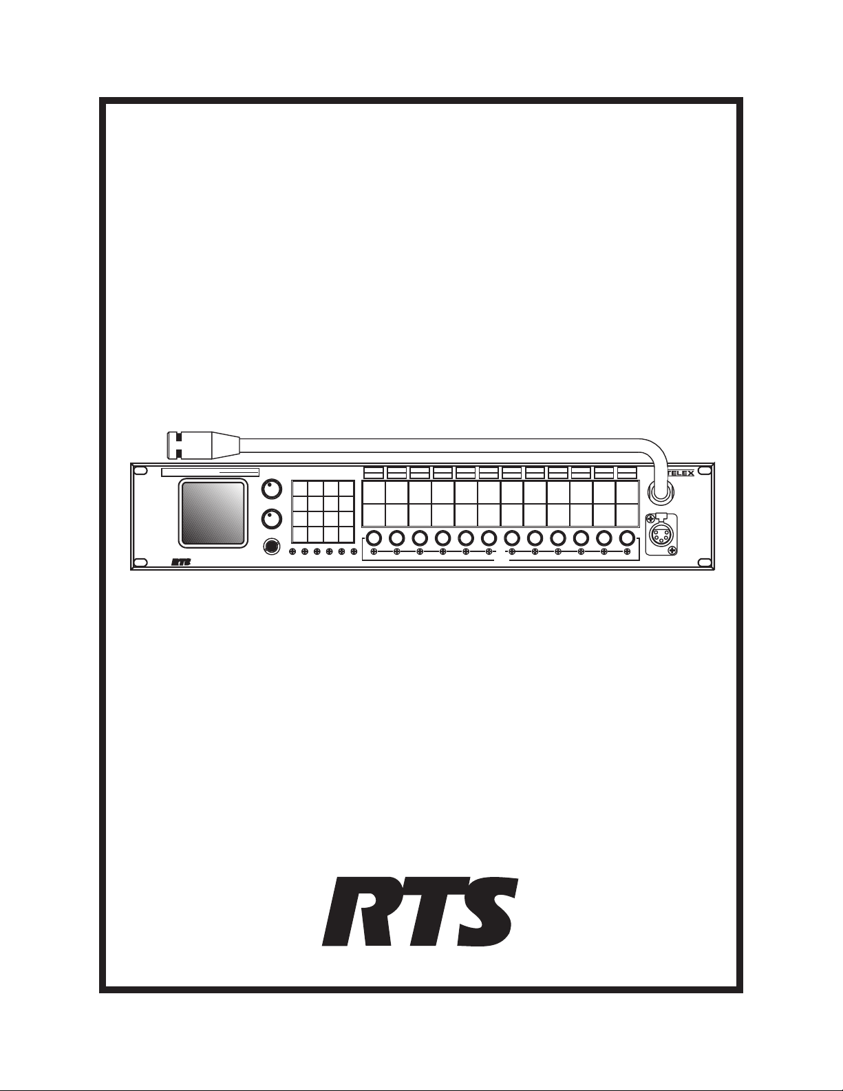
Model 803 Master Intercom Station
(Shown with Optional Panel Microphone)
9350-7547-000Rev A1,8/21/97
™
Page 2

Proprietary Notice
Customer Support
The RTS product information and design disclosed herein
were originated by and are the property of Telex
Communications, Inc. Telex reserves all patent,
proprietary design, manufacturing, reproduction, use and
sales rights thereto, and to any article disclosed therein,
except to the extent rights are expressly granted to others.
Copyright Notice
Copyright 1996 - 1997 by Telex Communications, Inc..
All rights reserved. Reproduction in whole or in part
without prior written permission from Telex is prohibited.
Unpacking And Inspection
Immediately upon receipt of the equipment, inspect the
shipping container and the contents carefully for any
discrepancies or damage. Should there be any, notify the
freight company and the dealer at once.
Warranty Information
RTS products are warranted by Telex Communications,
Inc. to be free from defects in materials and workmanship
for a period of three years from the date of sale.
The sole obligation of Telex during the warranty period is
to provide, without charge, parts and labor necessary to
remedy covered defects appearing in products returned
prepaid to Telex. This warranty does not cover any defect,
malfunction or failure caused beyond the control of
Telex, including unreasonable or negligent operation,
abuse, accident, failure to follow instructions in the
Service Manual or the User Manual, defective or
improper associated equipment, attempts at modification
and repair not authorized by Telex, and shipping damage.
Products with their serial numbers removed or effaced are
not covered by this warranty.
To obtain warranty service, follow the procedures entitled
"Procedure For Returns" and "Shipping to Manufacturer
for Repair or Adjustment".
This warranty is the sole and exclusive express warranty
given with respect to RTS products. It is the responsibility
of the user to determine before purchase that this product
is suitable for the user's intended purpose.
Any and all implied warranties, including the implied
warranty of merchantability are limited to the duration of
this express limited warranty. Neither Telex nor the dealer
who sells rts products is liable for incidental or
consequential damages of any kind.
Technical questions should be directed to:
Customer Service Department
RTS/Telex,
2550 Hollywood Way, Suite 207
Burbank, CA 91505 U.S.A.
Telephone: (818) 566-6700
Fax: (818) 843-7953
Return Shipping Instructions
Procedure For Returns
If a repair is necessary, contact the dealer where this unit
was purchased.
If repair through the dealer is not possible, obtain a return
authorization from:
Customer Service Department
Telex Communications, Inc.
Telephone: (800) 828-6107
Fax: (800) 323-0498
DO NOT RETURN ANY EQUIPMENT DIRECTLY
TO THE FACTORY WITHOUT FIRST
OBTAINING A RETURN AUTHORIZATION.
Be prepared to provide the company name, address,
phone number, a person to contact regarding the repair,
the type and quantity of equipment, a description of the
problem and the serial number(s).
Shipping to Manufacturer for Repair or Adjustment
All shipments of RTS products should be made via
United Parcel Service or the best available shipper,
prepaid. The equipment should be shipped in the original
packing carton; if that is not available, use any suitable
container that is rigid and of adequate size. If a substitute
container is used, the equipment should be wrapped in
paper and surrounded with at least four inches of
excelsior or similar shock-absorbing material. All
shipments must be sent to the following address and must
include the Return Authorization.
Factory Service Department
Telex Communications, Incorporated
West 1st Street
Blue Earth, MN 56013 U.S.A.
Upon completion of any repair the equipment will be
returned via United Parcel Service or specified shipper
collect.
2
Page 3

TableofContents
1 Description and Specifications 5
1.1 General Description 5
1.1.1 General 803 Features 5
1.1.2 803 Controls, Indicators, Connectors 6
1.1.2.1 Front Panel, User Controls 6
1.1.2.2 FrontPanel Trimmers 6
1.1.2.3 Front Panel, Connectors 6
1.1.2.4 Back Panel, Controls 6
1.1.2.5 Back Panel, Standard Connectors 6
1.1.2.6 Back Panel, Optional Connectors 6
1.1.2.7 Back PanelTrimmers 6
1.1.2.8 Internal DIP Switches and Jumpers 7
1.1.3 Setup Mode Description 7
1.1.3.1 Names for Setup Mode Features 7
1.1.3.2 Setup Mode Features 7
1.1.4 803 Compatibility with RTS Video ISO System 9
1.1.5 803 Compatibility with RTS Model 4000 IFB System
and Local IFB 10
1.1.6 Comparison of 803 and 802 10
1.1.6.1 Retained Features 10
1.1.6.2 New Features & Changes 10
1.2 Specifications 11
1.2.1 803 Master Station 11
1.2.2 External Power Supply 11
2Installation13
2.1 Unpacking 13
2.2 Option Cable Installation 14
2.2.1 General Information 14
2.2.2 Back Panel Connector Installation 14
2.2.3 4-Wire Option Cable Notes 14
2.2.4 IFB and ISO Option Cable Notes 14
2.2.4.1 General Notes 14
2.2.4.2 IFB 1 Cable Notes 15
2.2.4.3 IFB 2 Cable Notes 15
2.2.5 ISO 1 Cable Notes 15
2.2.5.1 ISO 2 Cable Notes 15
2.3 DIP Switch Settings 16
2.4 LED "Off" Brightness Jumpers 17
2.5 Front Panel Button Inserts 17
2.6 Setting the Key Code Switch 17
2.7 Resetting the 803 19
2.8 Mounting the 803 20
2.9 803 Connections 20
2.9.1 J101 Connector 21
2.9.2 J102 Connector 22
2.9.3 J103 Connector 23
2.9.4 J104 Connector 24
2.9.5 J104A Connector 25
2.9.6 J105 Connector 26
2.9.7 J106 Connector 27
2.9.8 J108 Connector 28
2.9.9 J109 Connector 29
2.9.10 J110 Connector 31
2.9.11 J111 Connector 32
2.9.12 J112 Connector 32
2.9.13 J201 Connector 33
2.9.14 J202 Connector 33
2.9.15 J203 Connector 33
2.9.16 Miscellaneous Connections 34
2.9.16.1 Local IFB 34
2.9.16.2 External ISO 34
2.9.16.3 Using the Talk KeyingSignal Outputs 34
3 Setup Mode 43
3.1 Introduction 43
3.2 Entering Setup Mode 43
3.3 Names for Setup Mode Features 43
3.4 Using the Setup Features 43
3.4.1
3.4.2
3.4.3
3.4.4
3.4.5
3.4.6
3.4.7
3.4.8
3.4.9
3.4.10
3.4.11
3.4.12
2W
Setup 43
2W/4W
4W
AUTO LISTEN
AUTO T ALK
BILAT SELECT
Setup 43
Setup 44
Setup 44
Setup 44
Setup 44
BUFFER RECALL
BUTTON LOCK
CALL DISABLE
CALLER ID
Setup 46
CHIME SELECT
EXT CONTACT
Setup 46
Setup 45
Setup 45
Setup 46
Setup 46
3
Page 4

3.4.13 G-RST (Global Reset) 46
3.4.14
3.4.15
3.4.16
3.4.17
3.4.18LSetup 47
3.4.19
3.4.20
3.4.21
3.4.22 MICS OFF 48
3.4.23
3.4.24
3.4.25
3.4.26
3.4.27
3.4.28
3.4.29
3.4.30
3.4.31
3.4.32
3.4.33
3.4.34
3.4.35
3.4.36
3.4.37
3.4.38
IHM
(Internal Headset Microphone) Setup 47
INSTANT MIC
IPM
Setup 47
ISO/4W
LATCH DISABLE
LOCAL IFB
MIC SELECT
NL
Setup 48
P1 and P2
PRE 1
PRESET EXCLUDE
PRESETS
R
(Right Headphone) Setup 49
RELAY 1
SP/L/R
SPECIAL PURPOSE
SPK
(Speaker) Setup 49
Setup 47
Setup 47
Setup 47
Setup 47
Setup 48
Setup 48
through
(Speaker Left/Right Select) Setup 49
PRE 6
Setup 48
through
Setup 48
Setup 48
RELAY 6
Setup 49
TALK TURNS OFF LISTEN
TALK TURNS ON LISTEN
TOT AL MUTE
VOX ENABLE
XHM
(External Headset Microphone) Setup 50
XPM
(External Panel Microphone) Setup 50
Setup 50
Setup 50
5.3 Headset or Panel Mic/Speaker Selection 53
5.4 Talking to an Intercom Channel 53
5.5 Listening to an Intercom Channel 53
5.6 Program Listen 53
5.7 Receiving Call Signals 53
5.8 Sending Call Signals 54
5.9 Using MICS OFF to Deactivate
Microphones on an Intercom Channel 54
5.10 Telephone Dialing with the Keypad 54
5.11 ISO Operation 54
5.11.1 ISO Operation in VCP Emulate Mode 54
5.11.2 ISO Operation using an External VCP Panel 55
5.12 IFB and SA (Stage Announce) Operation 55
5.12.1 Model 4001 or 4002 IFB Panel Emulation 55
5.12.2 Local IFB 55
6 Index 57
Setup 49
Setup 49
Setup 50
4 Adjustments 51
4.1 Back Panel Adjustments 51
4.1.1 Microphone Level Adjustments 51
4.1.2 ISO (Channel 15) Adjustments 51
4.1.3 USMB (Unswitched Microphone Balanced)
Output Level Adjustment 51
4.2 Front Panel Adjustments 51
4.2.1 VOXPM / VOX HM Adjustment 51
4.2.2 PGM1 / PGM2 Adjustment 51
4.2.3 LAMP DIM Adjustment 51
4.2.4 Null Adjustment 51
4.2.5 Sidetone Adjustment 52
5 Intercom Operation 53
5.1 Initial Volume Adjustment 53
5.2 Momentary vs Latching Button Operation 53
4
Page 5

1 Description and Specifications
1.1 General Description
The RTS Model 803 Master Intercom Station is an updated replacement to the popular Model 802. By employing many of the technological breakthroughs that have
occurred since the design of the 802, RTS has been able
to integrate into the 803 the complete circuitry for all 802
base features and options except squawk. For example,
call signaling is now standard on all twelve intercom channels. For applications requiring 4-wire operation, IFB
panel emulation or ISO panel emulation the circuitry is already there; you simply install an option cable to the back
panel, set one or two internal DIP switches (IFB and ISO
emulate only) and you're ready to go. For all other applications, everything you need is "in the box".
In terms of form, fit and function the 803 can directly replace the 802 with the following exceptions: 1) squawk is
not supported on the 803; 2) many users do not require a
front panel gooseneck microphone, so that is now supplied as a separate plug-in style microphone (unlike the
802 microphone which was permanently mounted); 3) the
803 includes built-in DC blocking for the intercom channels, so when connecting to powered intercom channels
that were previously connected to an 802, the external isolation capacitors are no longer required and may have to
be removed for best audio performance; 4) although seldom done in practice, the 802 could be DC powered; the
803 cannot.
In addition to it's role as a product replacement for the
802, the 803 also adds several new features in response to
the increasing communication needs of a variety of users.
Following is a general description of 803 features. Expanded descriptions of these features, a detailed comparison and contrast with the 802, and a list of specifications
may be found on the following pages.
1.1.1 General 803 Features
♦ Audio Inputs and Outputs: 12 intercom channels
(channels1-12); 3 auxiliary channels (channels13-
15); 2 program inputs; 2 headsetdynamic-mic inputs
and headphone outputs; 2 headset carbon-micinputs
and headphone outputs; 2 electret panel mic inputs;1
built-inspeaker and 1 switched speaker output;1 unswitched,balanced mic output (hot mic).
♦ Three Operating Modes: 1) normal operation, where
front panel controls are used for intercommunications
2) setup mode, where front panel buttons access the
user-programmable setup features; 3) DTMF mode,
where the keypad is used for telephone dialing on a
selected intercom channel.
♦ Audio Input Control: Complete control of audio mix
for all audio inputs via a combination of user controls, setup trimmers and the RS232/RS485 port. All
audio inputs are assignable, via setup mode, to left
headphone, right headphone, speaker, or any combination.
♦ Two-Wire and Four-Wire Operation: two-wire opera-
tion (with or without nulling) or four-wire operation
independently selectable for each intercom channel
via front panel setup mode; two-wire operation is
standard (balanced or unbalanced); four-wire intercom channel operation requires an optional 50-pin
connector); auxiliary channels 13 & 14 are four-wire
only; auxiliary channel 15 is two-wire only. All channels (intercom and auxiliary) support simultaneous
two-way communication (full duplex).
♦ ISO Operation: Compatible with RTS VIE-306 Video
ISO System; interfaces with external RTS VCP-6 or
VCP-12 ISO Panels, or emulates these panels internally (requires one optional 50-pin connector for
VCP-6 emulation; two for VCP-12 emulation).
♦ IFB Operation: Compatible with RTS Model 4000
IFB System; interfaces with external RTS Model
4001 or 4002 IFB panels, or emulates these panels internally (requires one optional 50-pin connector for
Model 4001 emulation; two for Model 4002 emulation). Also supports "local IFB", where any channel
may be configured as a stand-alone IFB.
♦ User-Programmable Setup Features: A varietyof pro-
grammable features allow the user to customize, simplify, and "automate" communication tasks. (Features
list includes original 802 features plus new features.)
♦ Control Signals: Call send and receive (compatible
with TW intercom system), with 3 chime tones (or no
chime) selectable for call send; talk-off send (compatible with RTS TW intercom system); global reset
send (compatible with RTSVIE-306 Video ISO System); DTMF send (for touch-tone dialing).
♦ Control Inputs and Outputs: 6 DPDT relay outputs
and 1 external switch contact input, all assignable via
the front panel setup-mode; 12 dedicated, open-collector keying outputs (one for each intercom channel); 1 RS232/RS485 port for remote control,
programming, and monitoring.
Note: control signals are applicable to the 12 intercom
channels only, and not to the 3 auxiliary channels.
5
Page 6

1.1.2 803 Controls, Indicators, Connectors
1.1.2.4 Back Panel,Controls
1.1.2.1 Front Panel,User Controls
♦ 1 Master volume control.
♦ 1 Program master volume control.
♦ 12 intercom channel level controls.
♦ 16-button keypad with backlit, user-replaceable la-
1
bels
; the keypad operates in normal, setup and
DTMF modes; normal and DTMF mode labeling is
printed on the button labels in normal text; setup
mode functions are printed on the button labels or on
the front panel next to the buttons in italics; the leftmost twelve buttons contain standard telephone keypad nomenclature in standard layout (letter
designations excluded).
♦ 12 conference talk/listen button pairs with backlit,
user-replaceable labels; buttons operate in normal
and setup modes; normal-mode intercom functions
are identified on the labels in normal text; setup
mode functions are printed in italics on the front
panel above the buttons.
1.1.2.2 Front Panel Trimmers
Trimmers are recessed and adjustableusing a number 0
flat-blade jeweler's screwdriver or equivalent.
Key code switch (selects 1-digit passcode for front-panel
access to setup mode, or no passcode, or locks out setup
mode).
1.1.2.5 Back Panel,Standard Connectors
♦ RS232/RS485.
♦ Ancillary.
♦ Relay/switch/ISO.
♦ Headset/microphone/program/hot mic.
♦ 2-wire intercom channels.
1.1.2.6 Back Panel,Optional Connectors
♦ IFB 1: used for Model 4001 emulate, or 4002 emu-
late when used with IFB 2 connector.
♦ ISO 1: used for Model VCP-6 emulate, or VCP-12
emulate when used with ISO 2 connector.
♦ IFB 2 / ISO 2: used with IFB1 or ISO1 connector
(but not both) for Model 4002 IFB Panel or VCP-12
ISO Panel emulation.
♦ 4-wire intercom channels.
♦ Panel mic VOX threshold adjustment.
♦ Dynamic-mic and carbon-mic headset VOX threshold
adjustment.
♦ Program 1 input level.
♦ Program 2 input level.
♦ Sidetone level.
♦ Master lamp brightness.
♦ Null adjustment: one trimmer for each intercom channel.
1.1.2.3 Front Panel,Connectors
♦ Carbon-mic headset.
♦ Electret gooseneck mic.
♦ Dynamic-mic headset (5-pin stereo standard, 4-pin
mono or 6-pin stereo w/mic switch input optional ).
1.1.2.7 Back Panel Trimmers
Trimmers are recessed and adjustableusing a number 0
flat-blade jeweler's screwdriver or equivalent.
♦ Front panel headset mic gain (adjusts both carbon
and dynamic).
♦ Front panel gooseneck microphone gain.
♦ External headset-mic gain.
♦ External electret-mic gain.
♦ ISO (channel 15) receive level.
♦ ISO (channel 15) null adjustment.
♦ Hot mic output level.
1 Button labels are printed black on clear acetate.
6
Page 7

1.1.2.8 Internal DIP Switches and Jumpers
1.1.3 Setup Mode Description
Note: Access to DIP switches and jumpers requires top
cover removal.
DIP switches
♦ IFB1 and IFB 2 select: enable the back panel IFB
emulation connectors and allocate front panel buttons
for IFB Panel emulation. Default: disabled.
♦ ISO 1 and ISO 2 select: enable the back panel ISO
emulation connectors and allocate front panel buttons
for ISO Panel emulation. Default: disabled.
♦ Number of active presets: selects whether multiple
presets may be activated at once, or only one at a
time. Default: multiple presets may be activated.
♦ Exclusive listen enable: when this feature isdisabled,
activating a talk button has no effect on the listen buttons; when this feature is enabled, activating a talk
button automatically turns off all active listen buttons
for all other channels except that channel. Default: exclusive listen disabled.
♦ Power-up reset option (warm or cold reset). See "Re-
setting the 803", page 19 for details. Default: warm
reset at power-up.
♦ Call light time-out select: selects 20 seconds or 20
minutes for time out of flashing button indication for
incoming calls. Default: 20 seconds.
♦ Number of active intercom channels: selects channels
1-6 active or channels 1-12 active. Default: all 12 intercom channels active.
1.1.3.1 Names for Setup Mode Features
Names for setup mode features are printed in italics on
the front panel as follows:
Setup Mode Features for Talk Buttons: Setup mode features that are accessed using the talk buttons are printed at
the very top of the front panel. For example, access BUTTON LOCK by pressing the TALK 1 button during setup
mode.
Setup Mode Features for Listen Buttons: Setup mode features that are accessed using the listen buttons are printed
just below the setup mode features for the talk buttons.
For example, access RELAY 1 by pressing the LISTEN 1
button during setup mode.
Setup Mode Features for Keypad Buttons: Some names
for setup features are printed in italics next to the buttons.
Some are printed in italics on the buttons. For example,
access the LOCAL IFB feature by pressing button 2 during setup mode. Access presets by tapping any one of the
buttons labeled PRE 1 through PRE 6. Labels that are not
italicized are operating features and not setup mode features.
Note: some italicized labels are not setup mode features,
but are submenu items for use with a particular setup
mode feature.
1.1.3.2 Setup Mode Features
♦ 801 emulation: Default: 801 emulation disabled.
♦ Internal/external ISO select: internal is used when the
803 emulates a VCP panel; external is used when the
803 connects to an external VCP panel, or when ISO
is not used. Default: external.
♦ ISO listen disable: turn off all activeconference chan-
nel listen buttons during ISO: Default: off (listens not
disabled during ISO).
♦ ISO enable/disable: Default: disabled.
♦ IFB talk disable: turns off all active conference chan-
nel talk buttons during IFB. Default: off.
Jumpers
Separate jumpers set the "off" brightness for the keypad
buttons and for the talk/listen buttons. Available settings
are high, low and off.
2W/4W Setup
Each intercom channel may be set for two-wire operation,
four-wire operation, or both (not applicable to auxiliary channels). For two-wire operation, nulling may also be optionally
turned on or off. Thus, theintercomchannels may be individually programmed to operate with a variety of inputs and
outputs. For example,two-wire operation won't work with a
typical two-way radio, which often requiresa four-wire, unbalanced connection. R TS "TW" belt packs and intercom
channels, of course, operatein two-wiremode, and nulling is
normally activa tedwhen connecting to TW devices.
Default setting: all channels set for two-wire operation
with nulling.
AUTO LISTEN Setup
Each listen button may be individually programmed for auto
listen. When auto listen is assigned to a channel, that channel's listen button will automatically turn on when there is an
incoming call signal from another intercom station.
Default setting: auto listen is disabled for all channels.
7
Page 8

AUTO TALK Setup
Each talk button can be individually programmed to automatically activate when an incoming call signal is received on its intercom channel. The microphone also
activates, so that the803 user can talk to the caller without having to press any buttons.
Default setting: auto talk disabled for all channels.
Default setting: caller ID is disabled on all intercom channels.
CHIME SELECT Setup
Chime select lets you select one of 3 chime tones for incoming call announcement on the intercom channels. The
currently selected tone always sounds at power-up or after
a reset.
BILAT SELECTSetup
If one or more of the auxiliary channels 13-15 are not being used with the ISO and IFB options, these channels
may be assigned to front-panel buttons (usually unused
keypad buttons) for talk and listen activation.
Default setting: channels 13 through 15 unassigned.
BUFFER RECALL Setup
The 803 has an internal buffer which stores the current
status (on or off) for all 24 talk and listen buttons. The
contents of this buffer can be recalled and stored in any
one of the 6 presets (the PRE 1 through PRE 6 buttons on
the keypad). You can then activate that preset button at
any time during normal operation to recall the saved talk
and listen button settings.
Default setting: N/A
BUTTON LOCK Setup
This feature locks selected talk and listen buttons in the
on or off position. You must also use this feature to unlock
buttons.
Default setting: all buttons unlocked.
CALL DISABLE Setup
Default setting: a single high-low tone
EXT CONTACT Setup
This feature lets you activate any one button on the front
panel (except CALL & SETUP) using an external switch.
You can also activate a group of buttons by assigning
those buttons to a preset and then activating the preset
with the external switch.
Default setting: the external switch activates the MIC ON
button on the keypad.
INSTANT MIC Setup
In order to talk to an intercom channel, both the MIC ON
button and the talk button for that channel must be on. In
some cases it may be convenient to have both of these activate when the talk button is pressed. This is referred to as
"instant mic".
Default setting: instant mic is disabled for all channels.
LATCH DISABLE Setup
Most front panel buttons can operate in both momentary
and latching mode. You may not want certain buttonsto
have the ability to latch (for example, a button that talks
to a radio transmitter). You can disable latching for these
buttons.
This feature disables or enables call signal reception on selected intercom channels. When call signal reception is
disabled on a channel, there will be no chime tone or button flash to indicate an incoming call. Outgoing call signals are not affected.
Default setting: call reception enabled for all intercom
channels.
CALLER ID Setup
Caller ID causes the listen button for an intercom channel
to flicker when audio is being received on that channel.
This provides a visual cue of which channel is talking.
You can set caller ID to provide this indication when the
listen button is on and/or off.
Default setting: latching operation enabled for all buttons
that support latching.
LOCAL IFB Setup
Any of the intercom channels 1-12 can beconverted into
a local IFB channel. (Not applicable to channels 13-15). A
local IFB channel normally sends a program feed to a remote listener. By pressing the talk button for the local IFB
channel, the 803 station operator can interrupt the program feed and then talk to the remote listener. The program source for a local IFB channel can be either of the
program 1 or 2 inputs, or the listen input for that channel.
Default setting: local IFB is off for all channels.
8
Page 9

MIC SELECT Setup
This feature selects which microphone inputs areactivated by the PANEL ON button in both the on and off positions.
Default setting: the PANEL ON button selects the front
panel gooseneck microphone in the on position and the
front panel headset microphone (either carbon or dynamic) in the off position.
PRESET EXCLUDE Setup
Selected talk and listen buttons may be excluded so that
they cannot be assigned for activation using the preset buttons.
Default setting: talk turns off listen is deactivated for all
channels.
TALK TURNS ON LISTEN Setup
You can set the talk button for any channel so that activating that talk button will automatically turn on the listen
button.
Default setting: talk turns on listen is deactivated for all
channels.
TOTAL MUTE Setup
Total mute lets you turn off all talk and listen buttons by
tapping a single button.
Default setting: no talk or listen buttons are excluded
from assignment to presets.
PRESETS Setup
Any combination of talk and listen buttons may be assigned for activation by any one of the 6 preset buttons.
Default setting: no presets setup.
RELAY Setup
Any of the 6 built-in relays may be assigned for activation
by selected front panel buttons.
Default setting: no relays assigned.
SP/L/R (Speaker Left/Right Select) Setup
Each audio input can be directed to the speaker, the left
headphone, the right headphone, or any combination of
the three.
Default setting: all audio inputs are assigned to the
speaker and to both the right and left headphones.
SPECIAL PURPOSE Setup
This feature is only available for special-order products.
TALK TURNS OFF LISTEN Setup
Occasionally, activating a talk button while the listen button is on may cause feedback, echo or other undesirable
sounds. This may only happen on selected channels, or it
may happen on all channels in certain environments or
with certain audio sources. You can eliminate this problem by setting selected listen buttons to automatically turn
off while their associated talk buttons are on.
Default setting: no total mute button assigned.
VOXENABLESetup
The 803 can be set for voice-activated microphone. When
this feature is enabled the microphone will remain off
when you are not speaking into it. When you do speak,
the microphone will turn on, and your voice will be transmitted on any channels that have talk buttons activated.
Default setting: vox disabled.
1.1.4 803 Compatibility with RTS Video ISO System
The 803 can be connected to an external VCP-6 or VCP12 Video ISOPanel. For external ISO, button activation at
the VCP panel causes deactivation of all conferencechannel talk buttons at the 803 (listen button deactivation may
also be setup via an internal 803 DIP switch), and the 803
mic audio is automatically routed to the VCP system.
The 803 can also emulate a VCP-6 or VCP-12 ISO Panel.
VCP-6 emulation requires installation of an optional 50pin cable and resetting internal DIP switches. VCP-6 emulation takes over 3 intercom channels (and their talk and
listen buttons) and auxiliary channel 15. VCP-6 emulation
can be installed along with Model 4001 IFB panel emulation. VCP-12 emulation is similar to VCP-6 emulation,
but requires installation of two 50-pin option cables. VCP12 emulation takes over 6 intercom channels and auxiliary channel 15. Also, IFB panel emulation is not possible
when VCP-12 panel emulation is installed. (However, local IFB is still possible on any unused intercom channels.)
9
Page 10

1.1.5 803 Compatibility with RTS Model 4000
IFB System and Local IFB
1.1.6 Comparison of 803 and 802
1.1.6.1 Retained Features
The 803 can be connected to an external 4001 or 4002
IFB Panel. For external IFB, button activation at the IFB
panel causes deactivation of all conference channel talk
buttons at the 803, and the 803 mic audio is automatically
routed to the IFB system.
The 803 can also emulate a 4001 or 4002 IFB Panel.
Model 4001 IFB Panel emulation requires installation of
an optional 50-pin cable and resetting internal DIP
switches. Model 4001 emulation takes over 3 intercom
channels (and their talk and listen buttons) and auxiliary
channel 13. Model 4001 emulation can be installed along
with VCP-6 ISO Panelemulation. Model 4002 IFBPanel
emulation is similar to Model 4001 emulation, but requires installation of two 50-pin option cables. Model
4002 emulation takes over 6 intercom channels and auxiliary channels 13 and 14. Also, VCP emulation isnot possible when Model 4002 emulation is installed. However,
external ISO is still possible.
Any intercom channel that is not being used for intercommunication or IFB/ISO panel emulation may be configured as a local IFB channel. This channel can be set to
normally monitor a program input at either the program 1
or 2 input. Or, if the local IFB channel is operated in 4wire mode, the listen input may be used as the program
source. Pressing the talk button for that channel disconnects the program input and causes the 803 operator's
voice to be heard at the IFB output.
Presets Total Mute
Relays Chime Select
Latch Disable Auto Listen
Preset Exclude Auto Talk
Special Purpose External Contact
Button Lock Talk Turns On Listen
Instant Mic Talk Turns Off Listen
Bilat Select
1.1.6.2 New Features & Changes
Model803 Model802
Depth 10" 14.25"
Weight 10 lb. 18 lb.
Std. Channels 12 6
Internal Jumpers 2 Many
Technology Surface-mount Through-hole
Indicators LED Incandescent lamp
Hot Mic Output Adj. to +26dBm Fixedat 0 dBm
Outputs Active balanced Transformer balanced
Listen Controls Front panel Adjustment board
Null Adjustment Front panel Adjustment board
Lamp DimAdjust Frontpanel Adjustment board
VO XAdjust Front panel N/A
Local IFB Yes Onlywith 862
Local IFB Pgm Adj Front panel None
DTMF Generator Yes No
Talk Off Signaling Yes No
Call Light Standard Optional
2W/4W Select Via software Via hardware
Listen Output Config Via software Via hardware
Headset Connector Optional 4-, 5-, or 6-pin 5/6-pin female
Auxiliary Connections 2) DB25 connectors Terminal strip
Program lockout Via software Via hardware
CPU Watchdog Yes No
Circuit Cards 3 Up to 14
Listen Activity Ind. 12 channels None
Mic inputs & levels Software adjustable Fixed
Panel Mic Removable Non-removable
Warm/Cold Start Front panel Adjustment board
Multi Listen Dim Yes No
Presets 6 4
Squawk No Optional
10
Page 11

1.2 Specifications
1.2.1 803 Master Station
Inputs
Dynamic Microphone
Source Impedance: 50 to 1000 ohms
Level: -55 dBu to -25 dBu
Carbon Microphone
Level: -15 dBu nominal
Excitation: 10 milliamperes
Four-Wire Receive Level
-20 dBu to 0 dBu into 40 kilohms
Program Input Level
0 dBu to +10 dBu into 40 kilohms
Outputs
Headphone Level
40 mW peak into 25 ohms
62.5 mW peak into 100 ohms
81 mW peak into 1000 ohms
Speaker Level
6 W peak power into 4 ohms
Unswitched Balanced Mic Out (Hot mic)
Adjustable to +25 dBm peak
Current Source Line Driver
Current: 10 mA pp nominal
Two Wire Level: 2 Vpp @ 200 ohms
Four Wire Level:6 Vpp @ 600 ohms
Relays
Bellcore surge withstand: 2.5 kV
Agency Approvals: UL,CSA,FCC Part 68
Contact Typeand Ratings
Type: SPDT (wired DPDT in parallel)
Maximum resistive current: 2 A
Maximum operating voltage:125 VAC, 110 VDC
Maximum switching capacity: 62.5 VA, 60 W
Minimum load:10 uA, 10 mVDC
Rated load, resistive: 0.5A@125VAC;1 A@ 30 VDC
Coil Ratings
Power Consumption:140 mW
Dielectric Strength: 1000 VAC
Key Outputs
0.4 A, 50 VDC maximum
Operating Distance
1 mile, nominal
RS232/RS485 Data
Baud rate: 2400 baud*
Data bits: 8
Stop bits: 1
Parity: none
Handshaking: none
* Initial connection at 2400 baud required. After connect-
ing the 803 may be set to 300, 600, 1200, 2400, 4800,
or 9600 baud.
Environmental
Ambient Temperature
Storage: -40°C to +85°C
Operating: 0°C to 50°C
Relative Humidity
10% to 90% Non-condensing
Mechanical
Color, Front Panel:Gray, Federal Standard 595A Color
#26492
Weight:10 lb.
Dimensions (Excluding connectors and panel mic)
Height: 3.5" (89 mm) high
Width: 19.0" (483 mm)
Depth: 10.0" (254 mm)
Electrical
Power, Nominal:43VA
Supplies
+5 VDC, 3 A
+15 VDC, 1.6 A
-15VDC, 0.3A
1.2.2 External Power Supply
General
Type: Model UP30431 Power Supply Specifications (Uni-
versal Input, Switching Type Supply)
Efficiency: 75% min.
MTBF: 50,000 hours
EMI: Meets FCC Class "B" and VDE Class "B"
Safety Approvals: UL / CSA / TUV/ CE Safety Marks
Environmental
Ambient Temperature
Storage: -20°C to 85°C
Operating: 0°C to 40°C
Relative Humidity: 0% to 95% Non-Condensing
Cooling: Free air convection
Input
Input Voltage: 100 VAC to 250 VAC at IEC connector
11
Page 12

Input Frequency: 47 Hz to 63 Hz
Inrush Current, Cold: 15 A @115 VAC, 30 A @230 VAC
Outputs
Power,Nominal: 43 VA
Supplies
+5 VDC,3A
+15 VDC, 1.6 A
-15 VDC, 0.3 A
Line regulation: +0.2%
Load regulation
+5 VDC: +/-3%
+15 VDC: +/-5%
-15 VDC: +/-10%
Ripple & Noise, 20 MHz BW: 1% max
Hold-up Time: 20 ms
Overvoltage Protection at main rated output: +15%
Overcurrent Protection: +150% load
Mechanical
Weight: 2 lb. (0.9 kg)
Length: 6.08" (154.4 mm)
Width: 3.33" (84.5 mm)
Height: 1.97" (50.0 mm)
Output Cord Length: 4 ft (1.2 m)
Output Connector: 5 pin DIN, male
Output Connections: pin l, return; pin 2, return, pin 3, +5
VDC; pin 4, -12 VDC; pin 5, +12 VDC
12
Page 13
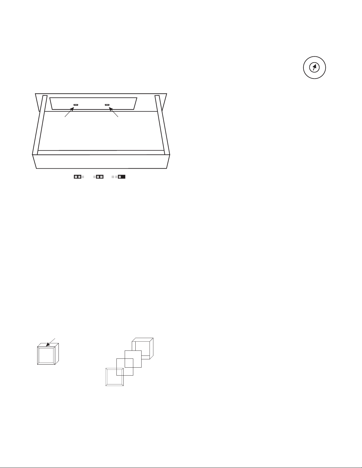
2 Installation
2.1 Unpacking
The package contents vary depending on what options are
included. Refer to Table 1 for the items included with
your 803. If anything appears missing or damaged,contact your dealer.
If your 803 includes option cables, proceed to "Option Cable Installation" on the next page. Otherwise, skip to "DIP
Switch Settings", page 16.
4-wire option cable Button insert sheet
ISO 1 / IFB 1 option cable
MICONMICONSPKRONSPKRONSPKRONPANE L
MIC
ON
STA
STA
2
1
STA17STA18STA19STA20STA21STA22STA23STA
IFB
IFB
2
1
IFB
IFB
2
1
ISO
ISO
2
1
ISO
ISO
2
1
STA
STA
2
1
CONF
CONF
CONF
2
1
CONF
CONF
CONF
2
1
TALK
TALK
TALK
CONF
CONF
CONF
2
1
LISTEN
LISTEN
LISTEN
CONF
CONF
CONF
2
1
TALK
TALK
TALK
MIC
STA
STA
STA
STA
STA
3
4
5
6
7
IFB
IFB6IFB7IFB8IFB9IFB10IFB11IFB12IFB
IFB
IFB
5
4
3
IFB
SA IFB
IFB
IFB
ISO
ISO
STA
ALL
4
3
ISO
ISO
5
4
3
ISO
ISO
5
4
3
STA
STA
3
4
5
CONF
CONF
5
4
3
CONF
CONF
5
4
3
TALK
TALK
CONF
CONF
5
4
3
LISTEN
LISTEN
CONF
CONF
5
4
3
TALK
TALK
IFB
1
LOCAL
ISO
RESET
6
ISO6ISO7ISO8ISO9ISO10ISO11ISO
STA
STA
6
7
CONF
CONF
7
6
CONF
CONF
7
6
TALK
TALK
CONF
CONF
7
6
LISTEN
LISTEN
CONF
CONF
2
1
LISTEN
LISTEN
PANE L
MIC
STA
8
24
IFB
2
GLOBAL
RESET
STA
8
CONF
1
8
CONF
1
8
TALK
CONF
1
8
LISTEN
CONF
3
LISTEN
ISO 2 / IFB 2 option cable
Figure 1. Option components
PRE1PRE2PRE3PRE
PANE L
MIC
STA
STA
9
10
CONF
ALL
TALK
TALK
IFB
3
PROD2
PROD1
TALK
TALK
STA
STA
9
10
CONF
CONF
9
CONF
CONF
9
TALK
TALK
CONF
CONF
9
LISTEN
LISTEN
CONF
CONF
4
LISTEN
LISTEN
STA
11
CONF
1
2
TALK
IFB5IFB6IFB4IFB
IFB
4
AUDIO
TALK
ALL
TALK
ALL
TALK
10
CONF
10
11
TALK
CONF
10
11
LISTEN
ALL
TALK
5
STA
12
CONF
1
LISTEN
LOGHTS
TALK
SPKR
MUTE
SLATE
MIC
CONF
TALK
CONF
LISTEN
IFB
1
4
STA
13
CONF
2
LISTEN
ALLSA1SA2SA3
7
ISO1
TALK
LOCAL
RESET
12
ISO1
LISTEN
IFB1
ISO
1
12
ISO
5
12
IFB
2
SET
SIGNAL
UP
STA
14
PGM
1
8
ISO2
TALK
PROD1
GLOBAL
LISTEN
RESET
ISO2
AUDIO
LISTEN
LISTEN
IFB2
ISO2ISO3ISO
ISO
GLOBAL
6
RESET
IFB
3
CALL
STA
15
PGM2PGM
ALL
SA1
IFB4IFB
TOTAL
MUTE
STA
16
SOUND
SA
SA
2
PROD2
LISTEN
LIGHTS
LISTEN
SA2
4
SA
ALL
Table 1. 803 Package contents for various option configurations
Description
803 Standard, No Options
803-C:4-Wire Option
803-C-G1:4-wire & IFB1 Options
803-C-G1G5:4-wire, IFB1 & IFB2 Options
803-C-G1-H1:4-wire, IFB1 & ISO1 Options
803-C-H1:4-wire & ISO1 Options
803-C-H1H5:4-wire, ISO1 & ISO2 Options
803-G1:IFB1 Option
803-G1G5:IFB1 & IFB2 Options
803-G1-H1:IFB1 & ISO1 Options
803-H1: ISO1 Option
803IntercomStation 111111111111
PowerSupply,100-250V,50-60Hz,1.2A 111111111111
803Manual 111111111111
Ribbon Cable Assy, 14-inch, with one 50-pin
connector to five10-pin connectors for ISO1
or IFB1
Ribbon Cable Assy, 17-inch, with one 50-pin
connector to five10-pin connectors for ISO2
or IFB2
Ribbon Cable Assy, 10-inch, 50-pin to 50-pin
for 4-wire option.
ButtonInsertSheet 1111111111
1121111211
1111
111111
803-H1H5: ISO1 & ISO2 Options
13
Page 14
2.2 Option Cable Installation
2.2.3 4-Wire Option Cable Notes
2.2.1 General Information
The connector openings for the option cables are labeled
on the back panel as follows:
ISO 1 Connector: Used for VCP-6 and VCP-12 ISO Panel
Emulation; provides connections for ISO1 through ISO6.
IFB 1 Connector: Used for 4001 and 4002 IFB Panel
Emulation; provides connections for IFB1 through IFB4
and SA1 (Stage Announce 1)
IFB 2 / ISO 2 Connector: Can be used with the ISO1 connector for VCP-12 Panel Emulation (provides the ISO7
through ISO12 connections). Or, can be used with the
IFB1 connector for 4002 IFB Panel Emulation (provides
the IFB5 through IFB8 and SA2 connections)
2.2.2 Back Panel Connector Installation
1. Remove the 12 top cover screws and remove the cover.
2. Select thedesired connector opening in the back panel.
Remove the 3/16 jack screw and the phillips screw
that hold the mesh screen and white plastic cable retaining clip in place.
3. Insert the 50-Pin"D" connector of the option cable into
the connector opening. The connector should be oriented the same way as the TWO WIRE LINE CONNECTOR that is already installed.
4. Reinstallthe white plastic cable retaining clip and the
screws. Note that the "D" connector has threaded inserts, so the hex nuts that were originally used are no
longer required.
5. Refer tothe following installation notes for each option
cable to complete the installation.
Connect the 4-wire cable to J55 on the main circuit board.
The red wire on the cable corresponds to pin 1 of J55.
Note: there are no internal DIP switches directly related to
the 4-wire option. You configureindividual channels to
operate in 4-wire mode via the front panel setup mode.
See "2W/4W Setup", page 43 for details.
2.2.4 IFB and ISO Option Cable Notes
2.2.4.1 General Notes
The priority and tally connectors are identified in Figure
2. Only one priority connector is used for each cable. It
determines who gets controlling access to IFB's and ISO's
when there is more than one IFB or ISO panel in the intercom system. Priority 1 overrides all panels set to priority
2, 3, or 4; priority 2 overrides priority 3 and 4 etc. When
an IFB or ISO button is pressed at a panel which has a
higher priority, any lower priority panels will be disconnected from that IFB or ISO until the buttonis released on
the higher priority panel. If the same IFB or ISO button is
activated on two panels with the same priority, both will
be able to talk to the IFB or ISO at the same time.
The tally connector is used in all cases. It distributes button-pressed signals throughout the intercom system to notify all other IFB or ISO panels when any IFB or ISO
button has been pressed.
Important! The priority and tally connectors can be installed backward if the correct location of pin 1 is not observed. Also, the connectors can be misaligned so that all
pins are not connected. Check carefully when installing.
Tally
Priority 4
(IFB Only)
4-Wire (J55)
Front Panel
IFB & ISO
(J325-J332)
Figure 3. Locations of option cable connectors on
the main circuit board
Priority 3
3M NO.3564
Priority 2
Priority 1
Pin 1 (Brown Wire)
All 10-Pin Connectors
Figure 2. Priority and tally connectors for IFB and
ISO option cables
14
Page 15

When you install an IFB or ISO option cable and set the
internal DIP switches as noted in the following paragraphs, specific front panel buttons will be reserved for
the installed option. The button insert sheet provides
standard button labels for these reserved buttons. See
"Front Panel Button Inserts", page 17 for details.
2.2.4.2 IFB 1 Cable Notes
♦ Connect the desired priority connector to J325 on the
main circuit board. Connectthe tally connector to J326.
♦ Set DIP switch S1-3 (page 16 ) to the ON position*.
DIP switch S2-8 may optionally be set to the on position if you want all talk buttons to automatically shut
off whenever any IFB button is activated.
♦ When installing button inserts for IFB 1 (page 17)
note that different buttons are used, depending on
whether or not another IFB or ISO connector is installed.
♦ Use a 50-pin cable to connect from the IFB 1 connec-
tor to a Model 4010 Central ElectronicsUnit. Typical
connections are shown in Figure 20, page 40. Refer
also to your Model 4010 Manual; if you are only using the IFB 1 connector and not IFB 2, connections
are the same as for a Model 4001 Control Station.
2.2.4.3 IFB 2 Cable Notes
♦ The IFB 2 cable should only be installed in addition
to the IFB 1 cable. If you install and activate thiscable, do not install and activate any ISO option cables.
♦ Connect the desired priority connector to J327 on the
main board. Connect the tally connector to J328.
♦ Set DIP switch S1-4 (page 16 ) to the ON position to
activate the IFB 2 connector*. (You should already
have set DIP switch S1-3 to the on position to activate the IFB 1 connector.)
2.2.5 ISO 1 Cable Notes
♦ Connect the desired priority connector to J329 on the
main circuit board. Connectthe tally connector to J330.
♦ Set DIP switches S2-4 and S2-6 (page 16 ) to the ON
position to activate and use this connector*. DIP
switch S2-5 may optionally be set to the ON position
if you want all conferencechannel listen buttons to
automatically shut off whenever any ISO button is activated (all conference channel talk buttons always
shut off during ISO).
♦ When installing button inserts for ISO 1 (page 17)
note that different buttons are reserved,depending on
whether or not another IFB or ISO connector is installed.
♦ Use a 50-pin cable to connect from the ISO 1 connec-
tor to a Model VIE-306 Video ISO Electronics Unit.
Typical connections are shown in Figure 20, page 40.
Refer to your Model VIE-306 Manual for further information. If you are only using the ISO 1 connector
and not ISO 2, connections are the same as for a
Model VCP-6.
2.2.5.1 ISO 2 Cable Notes
♦ The ISO 2 cable should only be installed in addition
to the ISO 1 cable. Also, if you install and activate
this cable, you cannot install and activate any IFB option cables.
♦ Connect the desired priority connector to J331 on the
main board. Connect the tally connector to J332.
♦ Set DIP switch S1-4 to the on position to activate the
ISO 2 connector*. (You should already have set DIP
switches S2-4 and S2-6 to the on position to activate
the ISO 1 connector.)
♦ Install the button inserts (page 17).
♦ Install the button inserts (page 17).
♦ Typical system connections are shown in Figure 18,
page 38. Refer also to your Model 4010 Central Electronics Manual. When using both the IFB 1 and IFB
2 connectors, connections are the same as for a
Model 4002 Control Station.
* Any time you change any of these DIP switch settings, you must perform a reset in order for them to take effect. All
previous setup mode programming will be erased during the reset.
♦ Typical system connections are shown in Figure 19,
page 39Refer to your Model VIE-306 Video ISO
Electronics Manual for connection information.
When using both the ISO 1 and ISO 2 connectors,
connections are the same as if you are connecting a
Model VCP-12 Control Station.
15
Page 16
2.3 DIP Switch Settings
Table 3. DIP switch S2 settings
Unless you are using the 803 for IFB or ISO operations,
you will probably not need to change any of the DIP
switch settings. However, briefly review the tables below
and make any required or optional changes before proceeding. Figure 4 showsthe locations of the DIP switches.
Access the switches by removing the 12 screws securing
the top cover.
Switches that are grayed-out in the tables require a reset
after changing, and will cause any setup-mode programming to be erased. All other switches do not require any
reset. See "Resetting the 803", page 19.
If you activate any of the DIP switches for the IFB or ISO
connectors on the back panel, change the front panel button inserts as described on the next page. Otherwise, proceed to "Setting the Key Code Switch", page 17.
Table 2. DIP switch S1 settings
Switch
No.
S1-1 Not used OFF
S1-2 Not used OFF
S1-3
S1-4
S1-5
S1-6
S1-7
S1-8 Not used OFF
Description
IFB enable for Model 4001/ 4002 emulate
No: OFF
Yes: ON
Note: 4001 / 4002 Emulation uses the
IFB1 / IFB2 connectorson the back panel.
Back Panel IFB / ISO connector
configuration:
Only IFB 1 and / or ISO 1 installed:OFF
IFB 1 & 2 or ISO 1 & 2 installed:ON
Number of presets (PRE 1 through PRE 6)
that can be activatedat the same time:
All may be activated at same time:OFF
Only one at a time: ON
Note: Each of the preset buttons (PRE1
through PRE6 on the keypad) can be
assigned to simultaneously activate
various combinations of front panel
buttons.See "Presets Setup", page 48.
Exclusive listen with talk
Talk does not turn off listens:OFF
Talk does turn off listens: ON
Note, when S1-6 is on:if a talk button is
pressed, all listen buttons except the one
associated with that talk button will turn off
until talk is released.However, listen
buttons may be manually reactivated
while a talk button is on.
Power-up reset options
Warm reset:OFF
Cold reset: ON
Note: see "Resetting the 803", page 19.
Default
Setting
OFF
OFF
OFF
OFF
OFF
Switch
No.
S2-1
S2-2
S2-3
S2-4
S2-5
S2-6
S2-7 Not used OFF
S2-8
Description
Call light time out select:
20 seconds:OFF
20 minutes: ON
Note: Call light time out determines how
long front panel listenbuttons will flash
after receiving an incoming call.
Number of active intercom channels
12: ON
6: OFF
Note: If S2-2 is set to off, the talk and
listen 6-12 buttonswill not operate at all
for intercom usage. The IFB1, IFB2, ISO1
and ISO2 options do use some or all of
these buttons; however, the position of
S2-2 does not affect any of these options.
801 Emulation
No: OFF
Yes: ON
ISO type select:
External ISO: OFF
VCP Emulate: ON
Note:In VCP emulate mode some front
panel buttons are used for ISO control as
showninFigure7,page18.Inexternal
ISO mode,an external VCP6A orVCP12A
is used forISO selection and the 803
microphone is usedto talk to the selected
ISO.For both types of ISO, S2-6 must be
ON to activate S2-4.
Disable all active conference channel
listen buttons during ISO?
No: OFF
Yes: ON
Note: All conference channel talk buttons
are automatically disabled during ISO.
ISO enable
Disable: OFF
Enable:ON
Turn off all active conferencechannel talk
buttons during IFB?
No: OFF
Yes: ON
Note: this feature applies only for Model
4001/4002 IFB Panel emulation.
DIP Switch S1DIP Switch S2
Back Panel
Figure 4. Locations of DIP switches
Default
Setting
OFF
ON
OFF
OFF
OFF
OFF
OFF
16
Page 17
2.4 LED "Off" Brightness Jumpers
There are 3 settings available for the"off" brightness of
the button LED's: off, low brightness and high brightness.
For most cases, the default setting will be satisfactory, and
the overall brightness of the lamps can be adjusted as
need via the front panel LAMP DIM trimmer.
J10, Talk/Listen
Button Off Brightness
J11 KeypadButton
Off Brightness
Back Panel
High Low Off
(Storage)
Figure 6. Locations of jumpers to select the "off"
brightness for the front panel buttons
2.6 Setting the Key Code Switch
KEY
The key code switch on the back panel controls access to the user-programmable setup
mode features. (The setup mode features are
described starting on page 43.) Key code
switch settings are as follows:
0: No access permitted (no one can program the 803)
1-9: User must enter this number before accessing
setup mode
A-F: No restrictions on access to setup mode (default)
Note: The key code switch has a stop at the 0 setting. Do
not attempt to rotate the switch through 0 to F.
To restrict access, select one of the settings 0 through 9.
Otherwise, leave the setting in the default position. If you
change the switch setting, the new setting will take place
immediately. Note that if you select the 0 position, you
will need to gain access to this switch if you ever need to
change any 803 programmable features.
CODE
5
4
6
3
2
1
0
F
E
C
D
7
8
9
A
B
2.5 Front Panel Button Inserts
The default setting for the front panel buttons is 12 conference intercom lines, with one talk and listen button pair
for each line. This configuration applies to both 2-wire
and 4-wire conference lines. If ISO or IFB options are installed, the front panel button configuration may be
changed by installing different inserts from the supplied
button insert sheet. Or, you can make your own custom inserts. Figure 7 summarizes the button usage for the various option configurations.
Pry out lens along edge Reassembly
CONF
7
TALK
CONF
7
TALK
Button
White filter
Label
Clear Lens
Figure 5. Button insert replacement
17
Page 18
DEFAULT CONFIGURATION
12 CONFERENCE LINES
(2-WIRE OR 4-WIRE)
CONF
1
TALK
CONF
1
LISTEN
CONF
2
TALK
CONF
2
LISTEN
CONF
3
TALK
CONF
3
LISTEN
CONF
4
TALK
CONF
4
LISTEN
CONF
5
TALK
CONF
5
LISTEN
CONF
6
TALK
CONF
6
LISTEN
CONF
7
TALK
CONF
7
LISTEN
CONF
8
TALK
CONF
8
LISTEN
CONF
9
TALK
CONF
9
LISTEN
CONF
10
TALK
CONF
10
LISTEN
CONF
11
TALK
CONF
11
LISTEN
CONF
12
TALK
CONF
12
LISTEN
IFB 1 CONNECTOR INSTALLED
9 CONFERENCE LINES;
REMAINING 6 BUTTONS EMULATE
A MODEL 4001 IFB PANEL
IFB 1 AND IFB 2
CONNECTORS INSTALLED
6 CONFERENCE LINES;
REMAINING 12 BUTTONS EMULATE
A MODEL 4002 IFB PANEL
ISO 1 CONNECTOR INSTALLED
9 CONFERENCE LINES;
REMAINING 6 BUTTONS EMULATE
A MODEL VCP-6 ISO PANEL
CONF
1
TALK
CONF
1
LISTEN
CONF
1
TALK
CONF
1
LISTEN
CONF
1
TALK
CONF
1
LISTEN
CONF
2
TALK
CONF
2
LISTEN
CONF
2
TALK
CONF
2
LISTEN
CONF
2
TALK
CONF
2
LISTEN
CONF
3
TALK
CONF
3
LISTEN
CONF
3
TALK
CONF
3
LISTEN
CONF
3
TALK
CONF
3
LISTEN
CONF
4
TALK
CONF
4
LISTEN
CONF
4
TALK
CONF
4
LISTEN
CONF
4
TALK
CONF
4
LISTEN
CONF
5
TALK
CONF
5
LISTEN
CONF
5
TALK
CONF
5
LISTEN
CONF
5
TALK
CONF
5
LISTEN
CONF
6
TALK
CONF
6
LISTEN
CONF
6
TALK
CONF
6
LISTEN
CONF
6
TALK
CONF
6
LISTEN
CONF
7
TALK
CONF
7
LISTEN
IFB
1
IFB
5
CONF
7
TALK
CONF
7
LISTEN
CONF
8
TALK
CONF
8
LISTEN
IFB
2
IFB
6
CONF
8
TALK
CONF
8
LISTEN
CONF
9
TALK
CONF
9
LISTEN
IFB
3
IFB
7
CONF
9
TALK
CONF
9
LISTEN
IFB
1
IFB
3
IFB
4
IFB
8
ISO
ISO
IFB
IFB
2
ALL
IFB
SA
4
1
SA
SA
1
2
IFB
ALL
ISO
ISO
ISO
2
3
ISO
5
6
1
4
ISO 1 AND ISO 2
CONNECTORS INSTALLED
6 CONFERENCE LINES;
REMAINING 12 BUTTONS EMULATE
A MODEL VCP-12 ISO PANEL
CONF
1
TALK
CONF
1
LISTEN
CONF
2
TALK
CONF
2
LISTEN
CONF
3
TALK
CONF
3
LISTEN
IFB 1 AND ISO 1
CONNECTORS INSTALLED
6 CONFERENCE LINES;
6 BUTTONS EMULATE
A MODEL 4001 IFB PANEL
CONF
1
TALK
CONF
1
LISTEN
CONF
2
TALK
CONF
2
LISTEN
CONF
3
TALK
CONF
3
LISTEN
6 BUTTONS EMULATE
A MODEL VCP-6 ISO PANEL
Figure 7. Button usage for various configurations of the 803
18
CONF
4
TALK
CONF
4
LISTEN
CONF
4
TALK
CONF
4
LISTEN
CONF
5
TALK
CONF
5
LISTEN
CONF
5
TALK
CONF
5
LISTEN
CONF
6
TALK
CONF
6
LISTEN
CONF
6
TALK
CONF
6
LISTEN
ISO
ISO
IFB
1
IFB
3
ISO
ISO
10
ISO
ISO
ISO
ISO
11
ISO
ISO
ISO
5
6
ISO
12
ISO
2
3
ISO
5
6
4
1
4
ISO
ISO
IFB
IFB
4
ISO
2
3
ISO
8
9
IFB
ALL
2
SA
1
1
7
Page 19

2.7 Resetting the 803
Prior to mounting the 803, perform a power-up reset.This
will allow any DIP switch changes to take effect, and it
will allow you to verify the operation of the front panel
displays. To perform the power-up reset, simply plug in
the power supply module.
At the start of reset, the front panel buttons will light in sequence. Then one listen button and one keypad button
will light simultaneously to display the version number.
The listen button displays the high digit and the keypad
button displays the low digit. For example, if the LISTEN
5 button and the "7" button on the keypad are both lit, the
version number is 5.7.
After the version number is displayed, the currently selected chime tone (if any) willsound. This is the tone that
you will hear for incoming call announcement. (You can
change this tone or turn it off. See "Chime Select Setup".
page 46.) At this time, the SPK ON button will also light
and remain on.
A warm reset only occurs underthe followingconditions:
♦ At power up if DIP switch S1-7 is set to the off posi-
tion AND NO HARDWARE DIP SWITCH SETTINGS HAVE BEEN CHANGED ANDTHE
BACKUP BATTERY IS FUNCTIONING CORRECTLY. (DIP switches that affect hardware opera-
tion are grayed-out in Tables2 or 3 , page 16.)
♦ When the user forces a warm reset during normal op-
eration (see below) AND NO HARDWARE DIP
SWITCH SETTINGS HAVE BEEN CHANGED
AND THE BACKUP BATTERY IS FUNCTIONING CORRECTLY.
Forcing a cold reset
Simultaneously press and hold the talk 1, 5, and 9 buttons
and the listen 2 button. Then, release the talk buttons
while continuing to hold the listen 2 button. After the
front panel lights begin to cycle release the listen 2 button.
Note: The rest of this page provides a detailed explanation
of the reset operation. You may skip this and proceed to
"Mounting the 803" on the next page; however, note that
changes to DIP switch settings after you have programmed the 803 (using setup mode, as described starting
on page 43) could erase your programmed settings.
The 803 has two reset modes: cold reset and warm reset.
A cold reset restarts the 803 and erases all setup mode programming. All front panel buttons are turned off (except
the SPK ON button, which always starts up in the on position). A warm reset restartsthe 803 and resets all front
panel buttons to the positions they were in before the reset
was initiated.
A cold reset occurs under the following conditions:
♦ DIP switch S1-7 is set to the on position and the 803
is powered up.
♦ The user forces a cold reset during normal operation.
(See "Forcing a Cold Reset", below.)
♦ The user changes any of the DIP switches that are
grayed-out in Tables 2 or 3 (page 16) and then performs a cold or warm reset by any means.
Forcing a warm reset
Simultaneously press and hold the talk 1, 5, and 9 buttons,
then release all 3 buttons.
♦ The backup battery fails and any kind of reset by any
means occurs.
19
Page 20
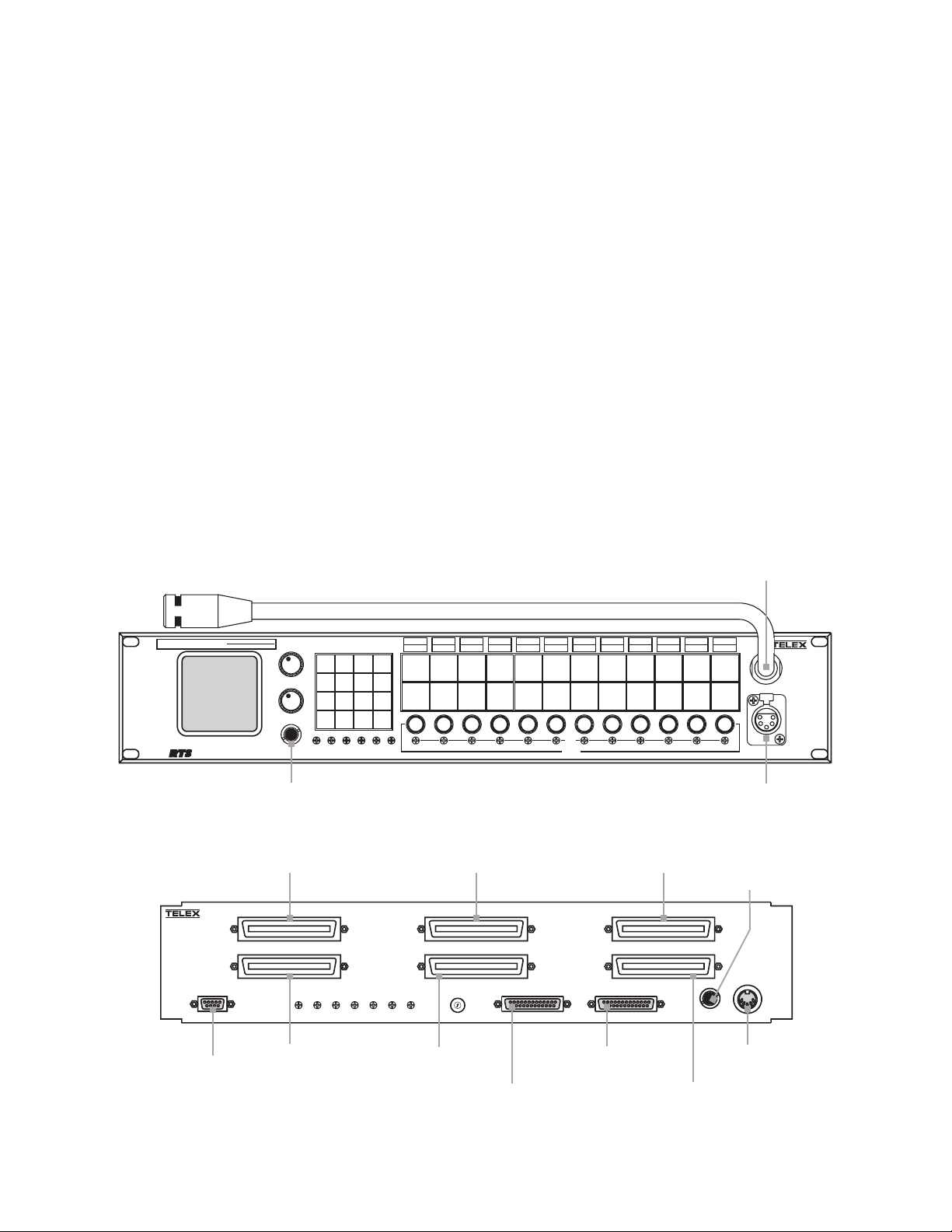
2.8 Mounting the 803
2.9 803 Connections
Note: If the mounting location for the 803 provides access
to the back panel controls and connectors, you should be
able to mount the 803 at this time. Otherwise, perform the
connections and adjustments as described in the following
sections before mounting the 803.
The 803 mounts in any standard equipment rack or bay
and occupies 2 rack spaces (3.5 inches high). Depth is
10.5 inches behind the front panel. Allow an additional 2
to 3 inches for connectors.
If the 803 will be used with a VCP-6/VCP-12 ISO Panel
or a 4001/4002 IFB Panel, it is generally located within
easy reach of these devices. General consideration should
also be given to the visibility of the controls and indicators from the operator's position to avoid eye or neck
strain during extended usage and to assure unobstructed
vision of other personnel or equipment. If necessary, discuss the positioning of the 803 and related components
with personnel who will have to use them to assure the
best setup. Once the 803 has been mounted, you should
be ready to connect it to the intercom system. Proceed to
the next page.
Refer to the connector pin-out tables and notes on the following pages for information about each connector. For
examples of connector usage, refer to the diagrams following the connector pin-out tables. After you connect the
803, you may have to configure one or more features
prior to operation. See "Setup Mode", starting on page 43 .
J201, page 33
ELECTRONIC SWITCH ACTION
MODEL 803
TM
MASTER STATION
®
TELEX COMMUNICATIONS,INC.
MADE INU.S.A.
MODEL 803
MASTER STATION
RS485 / RS232
J109, page 29
QUICKTOUCH TO LATCH
HOLDFOR MOMENTARY
MASTER
VOLUME
PROGRAM
VOLUME
CARB MIC
HEADSET
J203, page 33
J106, page 27
ISO 1
IFB 1
J103, page 23
2W
4W
NL
BUFFER
RECALL
HM PM
2W/4W
PRESET1
PRESET4
ISO/4W
VOXPMVOX
*
LOCAL
IFB
1
2
PRESET2 PRESET 3
4
5
PRESET5
MICS
7
8
OFF
0
P1
PGM1PGM
HM
EXTHMEXTPMR
SP/L/R
PRESET6
G RST
CALL
&
3
SETUP
SPKR
6
ON
PANEL
9
ON
MIC
#
ON
P2
SIDE
2
TONE
ISO
INSTANT
MIC
RELAY2
XPM
CONF
TAL K
CONF
LISTEN
BILAT
SELECT
RELAY3
IHM
CONF
2
3
TAL K
CONF
2
3
LISTEN
BUTTON
LOCK
RELAY1
IPM
CONF
1
TAL K
SPK
CONF
1
L
LISTEN
R
LAMP
DIM
J104 (IFB 2) page 24
J104A (ISO 2) page 25
IFB 2/ ISO 2
ANCILLARY
N
ISO
USMB
CODE
KEY
0
9
1
8
2
7
3
6
4
5
J102, page 22
TOTAL
CHIME
AUTO
AUTO
EXT
TALKTURNS
TALKTURNS
MUTE
SELECT
LISTEN
TALK
CONTACT
RELAY4
RELAY5
XHM
CONF
CONF
4
5
TAL K
TAL K
CONF
CONF
4
5
LISTEN
LISTEN
543216789101112
RELAY6
CONF
TAL K
CONF
LISTEN
CALL
DISABLE
CONF
6
7
TAL K
CONF
6
7
LISTEN
NULL
LEVEL
LATCH
DISABLE
CONF
TAL K
CONF
LISTEN
ONLISTEN
MIC
SELECT
CONF
8
9
TAL K
CONF
8
9
LISTEN
OFFLISTEN
VOX
ENABLE
CONF
10
TAL K
CONF
10
LISTEN
PRESETS CALLER ID
PRESET
EXCLUDE
CONF
TAL K
CONF
LISTEN
UPPERSWITCH
SPECIAL
LOWERSWITCH
PURPOSE
CONF
11
12
TAL K
CONF
11
12
LISTEN
DYN-MIC
HEADSET
J202, page 33
J101, page 21
J110, page 31
TWO WIRE LINE CONNECTOR
RELAY/ SW / ISO
FOUR WIRE LINE CONNECTOR
HDST / MIC/ PGM / USMB
J111, page 32
POWER IN
+5V 3A
+15V 1.6A
-15V 0.3A
EXT
SPKR
+5V RTN
RTN
J112, page 32
-15V+15V
J105, page 26J108, page 28
®
Figure 8. Connector reference view
20
Page 21

2.9.1 J101 Connector
Table 4. J101 connector pin-out
Intercom Audio
By default, 803 channels 1-12 are set for 2-wire bilateral
operation with nulling. This may be modified forselected
channels. See "2W/4W Setup", page 43 for further details.
The 803 uses a balanced configuration for 2-wire operation. The 803 channels can be connected to either balanced or unbalanced intercom stations or channels.
However, when making unbalanced connections, the
noise immunity of the balanced 803 channel will be compromised, and it is best to not distribute that channel over
cabling to other points in the intercom system. If you are
connecting the 803 to an unpowered (dry) intercomchannel, terminate that channel at one and only one point by
connecting a 200 ohm, 1/4-watt resistor across the intercom channel. If you are connecting a powered channel,
termination is usually accomplished by the power supply.
The 803 has built-in dc isolation, and so it is not necessary to use isolation capacitors when connecting to a powered intercom channel.
Talk Ke ying Signal Outputs
The 12 talk keying signal outputs are activated by the
803's talk buttons. These outputs may be used to activate
external devices such as relays. See "Using the Talk Keying Outputs", page 34.
Program 2
For a description of the program inputs, see this topic on
page 22.
Applications for J101
J101 may be used in several ways:
♦ Connecting to a TW intercom system using an RTS
Model 4012 System Interconnect Panel. An application is illustrated in Figure 15, page 35.
♦ Connecting to a TW intercom system using an RTS
Model 862 System Interconnect Panel. An application is illustrated in Figure 16, page 36.
♦ Direct interconnection of several 803 Master Stations.
An application is illustrated in Figure 17, page 37.
♦ Direct connection to intercom stations and other
audio inputs and outputs. Use an RTS Model 4024
Connecting Block or equivalent to break out the connections. The pin numbers on the 4024 Connecting
Block correspond to the pin numbers on the J101 connector.
Description Pin Numbers
2-wire bilateral audio, low, Ch 1 (2WBL1) 1
2-wire bilateral audio, high, Ch 1 (2WBH1) 26
2-wire bilateral audio, low, Ch 2 (2WBL2) 2
2-wire bilateral audio, high, Ch 2 (2WBH2) 27
2-wire bilateral audio, low, Ch 3 (2WBL3) 3
2-wire bilateral audio, high, Ch 3 (2WBH3) 28
2-wire bilateral audio, low, Ch 4 (2WBL4) 4
2-wire bilateral audio, high, Ch 4 (2WBH4) 29
2-wire bilateral audio, low, Ch 5 (2WBL5) 5
2-wire bilateral audio, high, Ch 5 (2WBH5) 30
2-wire bilateral audio, low, Ch 6 (2WBL6) 6
2-wire bilateral audio, high, Ch 6 (2WBH6) 31
2-wire bilateral audio, low, Ch 7 (2WBL7) 7
2-wire bilateral audio, high, Ch 7 (2WBH7) 32
2-wire bilateral audio, low, Ch 8 (2WBL8) 8
2-wire bilateral audio, high, Ch 8 (2WBH8) 33
2-wire bilateral audio, low, Ch 9 (2WBL9) 9
2-wire bilateral audio, high, Ch 9 (2WBH9) 34
2-wire bilateral audio, low,Ch 10 (2WBL10) 10
2-wire bilateral audio, high, Ch 10 (2WBH10) 35
2-wire bilateral audio, low,Ch 11 (2WBL11) 11
2-wire bilateral audio, high, Ch 11 (2WBH11) 36
2-wire bilateral audio, low,Ch 12 (2WBL12) 12
2-wire bilateral audio, high, Ch 12 (2WBH12) 37
Channel 1 Talk KeyingSignal Return 13
Channel 1 Talk Keying Signal 38
Channel 2 Talk KeyingSignal Return 14
Channel 2 Talk Keying Signal 39
Channel 3 Talk KeyingSignal Return 15
Channel 3 Talk Keying Signal 40
Channel 4 Talk KeyingSignal Return 16
Channel 4 Talk Keying Signal 41
Channel 5 Talk KeyingSignal Return 17
Channel 5 Talk Keying Signal 42
Channel 6 Talk KeyingSignal Return 18
Channel 6 Talk Keying Signal 43
Channel 7 Talk KeyingSignal Return 19
Channel 7 Talk Keying Signal 44
Channel 8 Talk KeyingSignal Return 20
Channel 8 Talk Keying Signal 45
Channel 9 Talk KeyingSignal Return 21
Channel 9 Talk Keying Signal 46
Channel 10 Talk Keying Signal Return 22
Channel 10 Talk Keying Signal 47
Channel 11 Talk Keying Signal Return 23
Channel 11 Talk Keying Signal 48
Channel 12 Talk Keying Signal Return 24
Channel 12 Talk Keying Signal 49
Program 2 Input Low 25
Program 2 Input High 50
21
Page 22

2.9.2 J102 Connector
Table 5. J102 connector pin-out
Relay Outputs
Each of the 6 internal relaysmaybe assigned for activation
by most of the front panel buttons.See "Relay 1 Through
Relay 6 Setup", page 49. The relays can be used for any
audio or low-current switching requirements. For each relay, the normal closed contact acts like a simple closed
switch (shorted to common) when the assigned front
panel button is not on, and the switch contact opens when
the button is activated. The normal open contact operation
is the reverse of the normal closed contact. The two common connections for each relay are electrically identical.
All relay connections are electrically isolated from the
rest of the 803 circuitry. Relayconnections are also available at J108, page 28.
External Switch Contact Input (XSW)
A switch may be connected between pins 13 and 38 for remote operation of a front panel button. By default, switch
contact closure will turn on the MIC ON button.To activate some other button, see "External Contact Setup",
page 46. The XSW connection is also available at J108.
Program Inputs
Program inputs 1 and 2 are balanced, line-level audio inputs. Nominal input levelis 0 dBm. Balanced or unbalanced sources may be connected, but use normal
precautions when connecting an unbalanced source (use
shielded cabling, keep leads short, avoid routing wires
near high voltage etc.). The program 1 and 2 inputs are adjustable via the PGM 1 and 2 trimmers on the front panel,
and they may be assigned to either right or left headphones or the internal speaker via front panel programming. The program 1 pins of J102 are electrically
identical to the program 1 pins of J111; the program 2
pins of J102 are electrically identical to the program 2
pins of J101, J105 and J111. For each program source,
use only one connect point.
Channels 13 and 14
J102 provides access to channels 13 and 14, which do not
normally have front panel buttons assigned. Channel 13 is
reserved when the Model 803 is configured for Model
4001 IFB emulation. Both channels 13 and 14 are reserved when the Model 803 is configured for Model 4002
IFB Station emulation. If one or both channels are not
used for IFB, they may be used as 4-wire channels. Use
the "Bilat" pins for output and the "Listen input" pins for
input. See "Bilat Select Setup", page 44, to assign front
panel buttons to use the channels. Note that there is no
provision for call signaling, mic-off signaling or keying
output signals on these channels.
Description Pin Numbers
Normal open contact 1
Relay 1 (K1)
Relay 2 (K2)
Relay 3 (K3)
Relay 4 (K4)
Relay 5 (K5)
Relay 6 (K6)
External Switch
Input (XSW)
Program 1 Input
Program 2 Input
No connection
Bilat 13
Bilat 14
Listen Input 13
Listen input 14
No connection
Common 26
Common 2
Normal closed contact 27
Normal open contact 3
Common 28
Common 4
Normal closed contact 29
Normal open contact 5
Common 30
Common 6
Normal closed contact 31
Normal open contact 7
Common 32
Common 8
Normal closed contact 33
Normal open contact 9
Common 34
Common 10
Normal closed contact 35
Normal open contact 11
Common 36
Common 12
Normal closed contact 37
Ground 13
Normal open contact 38
Low 14
High 39
Low 15
High 40
16
41
Low 17
High 42
Low 18
High 43
Low 19
High 44
Low 20
High 45
21
46
22
47
23
48
24
49
25
50
22
Page 23

2.9.3 J103 Connector
Table 6. J103 connector pin-out
J103 is an optional connector provided when the IFB 1 option is installed. Typical applications of this connector are
shown in Figure 18, page 38 and Figure 20, page 40.
Description Pin Numbers
IFB button #1 1
IFB button #2 26
IFB button #3 2
IFB button #4 27
IFB Priority 1
Connections
IFB Priority 2
Connections
IFB Priority 3
Connections
IFB Priority 4
Connections
IFB 1-4 Tallies and
SA1 Tally
No connection 48
Ground 24
Ground 49
Ground 25
Ground 50
SA1 button 3
Ground 28
Audio High 4
Audio Low 29
Ground 5
Ground 30
IFB button #1 6
IFB button #2 31
IFB button #3 7
IFB button #4 32
SA1 button 8
Ground 33
Audio High 9
Audio Low 34
Ground 10
Ground 35
IFB button #1 11
IFB button #2 36
IFB button #3 12
IFB button #4 37
SA1 button 13
Ground 38
Audio High 14
Audio Low 39
Ground 15
Ground 40
IFB button #1 16
IFB button #2 41
IFB button #3 17
IFB button #4 42
SA1 button 18
Ground 43
Audio High 19
Audio Low 44
Ground 20
Ground 45
IFB #1 Tally 21
IFB #2 Tally 46
IFB #3 Tally 22
IFB #4 Tally 47
SA1 Tally 23
23
Page 24

2.9.4 J104 Connector
J104 is an optional connector provided when the IFB 2
connector is installed. A typical application of this connector is shown in Figure 18, page 38.
Table 7. J104 connector pin-out for IFB usage (see
Table 8 for ISO usage)
Description Pin Numbers
IFB button #5 1
IFB button #6 26
IFB button #7 2
IFB button #8 27
IFB Priority 1
Connections
IFB Priority 2
Connections
IFB Priority 3
Connections
IFB Priority 4
Connections
IFB 5-8 Tallies and
SA2 Tally
No connection 48
Ground 24
Ground 49
Ground 25
Ground 50
SA2 button 3
Ground 28
Audio High 4
Audio Low 29
Ground 5
Ground 30
IFB button #5 6
IFB button #6 31
IFB button #7 7
IFB button #8 32
SA2 button 8
Ground 33
Audio High 9
Audio Low 34
Ground 10
Ground 35
IFB button #5 11
IFB button #6 36
IFB button #7 12
IFB button #8 37
SA2 button 13
Ground 38
Audio High 14
Audio Low 39
Ground 15
Ground 40
IFB button #5 16
IFB button #6 41
IFB button #7 17
IFB button #8 42
SA2 button 18
Ground 43
Audio High 19
Audio Low 44
Ground 20
Ground 45
IFB #5 Tally 21
IFB #6 Tally 46
IFB #7 Tally 22
IFB #8 Tally 47
SA2 Tally 23
24
Page 25

2.9.5 J104A Connector
Table 8. J104A connector pin-out for ISO usage
J104A is an optional connector provided when the ISO 2
connector is installed. A typical application of this connector is shown in Figure 19, page 39.
Description Pin Numbers
ISO button #7 1
ISO button #8 26
ISO button #9 2
ISO button #10 27
Priority 1
Connections
Priority 2
Connections
Priority 3
Connections
No connection
Tallies
ISO button #11 3
ISO button #12 28
Audio High 4
Audio Low 29
Ground 5
Ground 30
ISO button #7 6
ISO button #8 31
ISO button #9 7
ISO button #10 32
ISO button #11 8
ISO button #12 33
Audio High 9
Audio Low 34
Ground 10
Ground 35
ISO button #7 11
ISO button #8 36
ISO button #9 12
ISO button #10 37
ISO button #11 13
ISO button #12 38
Audio High 14
Audio Low 39
Ground 15
Ground 40
16
41
17
42
18
43
19
44
20
45
ISO #7 Tally 21
ISO #8 Tally 46
ISO #9 Tally 22
ISO #10 Tally 47
ISO #11 Tally 23
ISO #12 Tally 48
Ground 24
Ground 49
Global Reset Tally 25
Global Reset button 50
25
Page 26

2.9.6 J105 Connector
Table 9. J105 connector pin-out
J105 is an optional connector provided when the 4-wire
connector is installed. A typical application of this connector is shown in Figure 21, page 41.
Description Pin Numbers
4-Wire Listen Low 1 (4WLL1) 1
4-Wire Listen High 1 (4WLH1) 26
4-Wire Listen Low 2 (4WLL2) 2
4-Wire Listen High 2 (4WLH2) 27
4-Wire Listen Low 3 (4WLL3) 3
4-Wire Listen High 3 (4WLH3) 28
4-Wire Listen Low 4 (4WLL4) 4
4-Wire Listen High 4 (4WLH4) 29
4-Wire Listen Low 5 (4WLL5) 5
4-Wire Listen High 5 (4WLH5) 30
4-Wire Listen Low 6 (4WLL6) 6
4-Wire Listen High 6 (4WLH6) 31
4-Wire Listen Low 7 (4WLL7) 7
4-Wire Listen High 7 (4WLH7) 32
4-Wire Listen Low 8 (4WLL8) 8
4-Wire Listen High 8 (4WLH8) 33
4-Wire Listen Low 9 (4WLL9) 9
4-Wire Listen Audio Inputs, Channels 1-12
4-Wire Listen High 9 (4WLH9) 34
4-Wire Listen Low10 (4WLL10) 10
(Items in parenthesis are the schematic abbreviations)
4-Wire Listen High 10 (4WLH10) 35
4-Wire Listen Low11 (4WLL11) 11
4-Wire Listen High 11 (4WLH11) 36
4-Wire Listen Low12 (4WLL12) 12
4-Wire Listen High 12 (4WLH12) 37
4-Wire Talk Low 1 (2WBL1) 13
4-Wire Talk High 1 (2WBH1) 38
4-Wire Talk Low 2 (2WBL2) 14
4-Wire Talk High 2 (2WBH2) 39
4-Wire Talk Low 3 (2WBL3) 15
4-Wire Talk High 3 (2WBH3) 40
4-Wire Talk Low 4 (2WBL4) 16
4-Wire Talk High 4 (2WBH4) 41
4-Wire Talk Low 5 (2WBL5) 17
4-Wire Talk High 5 (2WBH5) 42
4-Wire Talk Low 6 (2WBL6) 18
4-Wire Talk High 6 (2WBH6) 43
4-Wire Talk Low 7 (2WBL7) 19
4-Wire Talk High 7 (2WBH7) 44
4-Wire Talk Low 8 (2WBL8) 20
4-Wire Talk High 8 (2WBH8) 45
4-Wire Talk Low 9 (2WBL9) 21
4-Wire Talk Audio Outputs,Channels 1-12
4-Wire Talk High 9 (2WBH9) 46
4-Wire Talk Low 10 (2WBL10) 22
4-Wire Talk High 10 (2WBH10) 47
4-Wire Talk Low 11 (2WBL11) 23
4-Wire Talk High 11 (2WBH11) 48
(The 4-wire talk output s are electrically identical to the 2 -wire bilats at J101)
4-Wire Talk Low 12 (2WBL12) 24
4-Wire Talk High 12 (2WBH12) 49
Program
2 Input
Low 25
Hi 50
26
Page 27

2.9.7 J106 Connector
Table 10. J106 connector pin-out
J106 is an optional connectorprovided when the ISO 1
connector is installed. Typical applications of this connector are shown in Figure 20, page40 and Figure19,page39.
Description Pin Numbers
ISO button #1 1
ISO button #2 26
ISO button #3 2
ISO button #4 27
Priority 1
Connections
Priority 2
Connections
Priority 3
Connections
No connection
Tallies
ISO button #5 3
ISO button #6 28
Audio High 4
Audio Low 29
Ground 5
Ground 30
ISO button #1 6
ISO button #2 31
ISO button #3 7
ISO button #4 32
ISO button #5 8
ISO button #6 33
Audio High 9
Audio Low 34
Ground 10
Ground 35
ISO button #1 11
ISO button #2 36
ISO button #3 12
ISO button #4 37
ISO button #5 13
ISO button #6 38
Audio High 14
Audio Low 39
Ground 15
Ground 40
16
41
17
42
18
43
19
44
20
45
ISO #1 Tally 21
ISO #2 Tally 46
ISO #3 Tally 22
ISO #4 Tally 47
ISO #4 Tally 23
ISO #4 Tally 48
Ground 24
Ground 49
Global Reset Tally 25
Global Reset
button
50
27
Page 28

2.9.8 J108 Connector
Table 11. J108 connector pin-out
Relays and External Switch
The relay and external switch connections at J108 are electrically identical to those at J102. See "J102 Connector",
page 22.
External ISO Connection
For external ISO, the 803 is used with an externalVCP
panel located adjacent to the 803. Activating any of the
ISO buttons on the external VCP panel sends a control signal to the 803 which causes all active talk channels to deactivate. The 803's microphone audio is then output at the
bilat 15 pins on the J108 connector. This audio output is
connected to the audio input of the VCP, which then sends
it to the ISO system.
To connect external ISO:
Connect J108, pin 13 of the 803 to TB2, pin 2 of the
VCP; connect J108, pin 25 to TB2, pin 3. Thisis the
audio output connection from the 803 to the VCP.
Connect J108, pin 12 of the 803 to TB4, pin 4 of the
VCP; connect J108, pin 24 to TB4, pin 3. This is the control input connection from the VCP to the 803.
Set DIP switch S2-6 to ON; S2-5 to ON or OFF as desired; S2-4 to OFF. For DIP switch details, see page 16.
Bilat 15
As previously described, bilat 15 can be used for ISO. If
ISO is not required, bilat 15 can be used asa 2-wire intercom channel, or for audio output or input. Note that there
is no provision for call signaling, mic-off signaling or keying output signals for bilat 15. To assign talk andlisten
keys to use bilat 15, see "Bilat Select Setup", page 44.
Note that there is no LISTEN control on the front panel
for bilat 15. Adjust the listen level at the "R ISO" trimmer
on the back panel. Adjust nulling at the "N ISO" trimmer
on the back panel.
Description Pin Numbers
Normal open contact 1
Relay 1 (K1)
Relay 2 (K2)
Relay 3 (K3)
Relay 4 (K4)
Relay 5 (K5)
Relay 6 (K6)
External Switch Input (XSW) Normal Open
Contact
XSW and YSW Common 10
External Switch Input (YSW) Normal Open
Contact (Not used on base mode)
External ISO
control input
from VCP
Bilat 15
Normal closed contact 2
Common 14
Normal open contact 15
Normal closed contact 16
Common 3
Normal open contact 4
Normal closed contact 5
Common 17
Normal open contact 18
Normal closed contact 19
Common 6
Normal open contact 7
Normal closed contact 8
Common 20
Normal open contact 21
Normal closed contact 22
Common 9
23
11
TB4, Pin 3 (Common) 24
TB4, Pin 4 (Normal open
contact)
Audio Low 25
Audio High 13
12
28
Page 29

2.9.9 J109 Connector
Table 12. J109 connector pin-out
J109 can be used to connect to a computer or terminal for
remote access and control of the 803. Use a standard
RS232 cable (not null modem). Default RS232 port settings are 2400 baud*, 8 data bits, 1 stop bit and no parity.
No handshaking is used. You can send commands to do
any of the following:
♦ operate all front panel buttons or read their settings
♦ inhibit manual operation of front panel buttons
♦ read the settings of all DIP switches
♦ read and modify the 803's programmable memory
♦ operate all relays, talk/listen gates and key lines inde-
pendently of button positions
♦ initiate a reset (warm or cold)
♦ request notification upon operator initiation of reset
♦ send a command upon operator initiation of any func-
tion, front panel or DIP switch change
Command Structure
Most commands generally consist of 3 parts: a one- or
two-character command letter, followed by a numeric
modifier, followed by an operator. Commands which perform memory operations are structured as follows: a oneor two-character command letter, followed by a memory
location, followed by a memory operator. If the memory
operator modifies memory, it will be followed by one or
more bytes of information to be sent to memory. All commands must be followed by a carriage return. All commands, except memory load commands, are limited to
128 characters in length.
Command Letters
Description Pin Numbers
NC 1
RS232TX 2
RS232 RX 3
NC 4
GND 5
NC 6
NC 7
RS485 8
RS485 9
Numeric Modifiers
Buttons and certain functions are numbered as follows:
1-12 top row of buttons
13-24 second row of buttons
25-40 keypad buttons (left-to-right, top-to-bottom)
41 external camera iso input
42 external global reset tally #1
43 external mic
44 external global reset tally #2
45-56 call light detectors
57-68 listen activity detectors
69 special mute (on special order software)
70 headset mic switch
71 carbon mic switch
72 external carbon mic switch
73 vox detect
74 external preset 3
Certain other items are also numbered as follows:
Relays: 1-6
Keying outputs: 1-12
Gates (icom channels): 1-15
LEVEL controls: 1-12
A attenuator
B button
C cold start
D dump memory as bytes
DW dump memory as words
E eavesdrop (watch 803 button activity)
F full duplex
G gate (icom channels 1-15)
H half Duplex
I inhibit
K keying signal outputs
M memory operation (for factory testing)**
R relay
V version
W warm start
Z baud rate change
Operators
+ turn on the item specified in the numeric modifier
- turn off the item specified in the numeric modifier
? read the item specified in the numeric modifier
* You must connect at 2400 baud. After you connect, the
803 may be reprogrammed for any of the following
baud rates: 300, 600, 1200, 2400, 4800, or 9600. To
change the baud rate, send Z300 or Z9600 etc.
** Memory operations can modify the standard operation
of controls, but require a knowledge of controller programming and the 803 I/O list.
29
Page 30

Table 13. Examples of commands and responses
Description.. .. .. .. .. .. .. .. .. .. .. .. .. ..CommandSequence. ..803Response
Turnbutton12on:.. .. .. .. .. .. .. .. .. .. .. ..Bl2+. .. .. .. .. .. ..none
Turnbutton12off:.. .. .. .. .. .. .. .. .. .. .. ..B12-. .. .. .. .. .. ..none
Testbutton12status:. .. .. .. .. .. .. .. .. .. .. ..B12?.. .. .. .. .. ..+or-
Inhibitbutton12usebyoperator(lockincurrentposition). ..I12+.. .. .. .. .. ..none
Allow button12usebyoperator:. .. .. .. .. .. .. .. ..I12-. .. .. .. .. .. ..none
Testifbutton12isinhibited:. .. .. .. .. .. .. .. .. ..I12?. .. .. .. .. .. ..+or-
Assignrelay5 tobutton12:. .. .. .. .. .. .. .. .. ..B12R5+. .. .. .. .. ..none
Removerelay5assignmentfrombutton12:. .. .. .. .. ..B12R5-. .. .. .. .. ..none
Identifyrelay(s)assignedtobutton12:.. .. .. .. .. .. ..B12R?.. .. .. .. .. ..1,or2,or3 etc.(ormorethanone)
Turnonrelay5:.. .. .. .. .. .. .. .. .. .. .. .. ..R5+. .. .. .. .. .. ..none
Turnoffrelay5:.. .. .. .. .. .. .. .. .. .. .. .. ..R5-. .. .. .. .. .. ..none
Check relay 5status:. .. .. .. .. .. .. .. .. .. .. ..R5?. .. .. .. .. .. ..+or-
Turnongate12:.. .. .. .. .. .. .. .. .. .. .. .. ..G12+.. .. .. .. .. ..none
Turnoffgate12:. .. .. .. .. .. .. .. .. .. .. .. ..G12-.. .. .. .. .. ..none
Check gate12status:. .. .. .. .. .. .. .. .. .. .. ..G12?.. .. .. .. .. ..+or-
Turnonkeyingoutput12. .. .. .. .. .. .. .. .. .. ..K12+.. .. .. .. .. ..none
Turnoffkeying output12. .. .. .. .. .. .. .. .. .. ..K12-.. .. .. .. .. ..none
Check keyingoutput12status:.. .. .. .. .. .. .. .. ..K12?.. .. .. .. .. ..+or-
Startingatmemorylocation01F0, load04,0D,0A &00.. ..M0lF0L04,0D,0A,00. ..none
Atmemorylocation01F0,setbit. .. .. .. .. .. .. .. ..M0IF0S40. .. .. .. ..
Atmemorylocation01F0,resetbit.. .. .. .. .. .. .. ..M0lF0R40. .. .. .. ..
Readmemorylocation 01F0. .. .. .. .. .. .. .. .. ..M01F0?. .. .. .. .. ..4C
Dumpmemoryatlocation 01F0(asbytes).. .. .. .. .. ..D01F0.. .. .. .. .. ..0100:040D0A 00
Dumpmemoryatlocation 01F0(aswords). .. .. .. .. ..DW0IF0.. .. .. .. ..0100:0904000A
AdjustattenuatorLEVEL 9tolevel10(rangeis0-15). .. ..A0910. .. .. .. .. ..none
Check attenuatorLEVEL9.. .. .. .. .. .. .. .. .. ..A09. .. .. .. .. .. ..10
Turneavesdropmodeon:. .. .. .. .. .. .. .. .. .. ..E+.. .. .. .. .. .. ..none(Statusofbuttonsisreportedasthey
change. Examples:button12turnedon=B12+;button12turnedoff=B12-.)
Turneavesdropmodeoff:. .. .. .. .. .. .. .. .. .. ..E-.. .. .. .. .. .. ..none
Eavesdropmodeactive:.. .. .. .. .. .. .. .. .. .. ..E?.. .. .. .. .. .. ..+(active)or- (inactive)
Warmstart:.. .. .. .. .. .. .. .. .. .. .. .. .. ..W.. .. .. .. .. .. ..W orC (waitforresettofinish)
Coldstart:. .. .. .. .. .. .. .. .. .. .. .. .. .. ..C.. .. .. .. .. .. ..C (waitforresettofinish)
Versionnumber:. .. .. .. .. .. .. .. .. .. .. .. ..V.. .. .. .. .. .. ..TLX0XX(Telexversion0X.X)
Fullduplex.. .. .. .. .. .. .. .. .. .. .. .. .. ..F. .. .. .. .. .. .. ..Usercommandsechoed
Halfduplex(default). .. .. .. .. .. .. .. .. .. .. ..H.. .. .. .. .. .. ..Usercommandsnotechoed
Changebaudrateto1200baud.. .. .. .. .. .. .. .. ..Z1200.. .. .. .. .. ..Changeto1200baud(defaultis2400baud)
30
Page 31

Error Handling for the RS232 and RS485 Ports
Upon detection of an error in a command, the 803 will
typically ignore the command and send out an error message consisting of the letter E along with a 2 digit code as
follows:
E00 syntax error
E01 output buffer overflow
E02 unrecognizable command
E03 Unrecognized operator (+, - or ? expected)
E04 numeric modifier out of range
E10 RS-232 framing or parity error
E20 RS-422/485 framing or parity error
Note: Relays are updated every time a button is pushed or
released. This means, for example, that if the host computer turns on a relay, it may be turned off the next time
the 803 operator pushes any button. Keying output signals
and gates may also be affected if the operator pushes the
button associated with that key or gate.
2.9.10 J110 Connector
If desired, an external speaker may be connected and used
in place of the internal speaker. Connector insertion
causes the internal speaker to disconnect.
J110
1/4-inch, 5-conductor Phone Jack
with Switched Contacts
5
4
3
2
1
Figure 9. J110 connector pin-out
No connection
No connection
To internal speaker
Speaker amp output
Common
31
Page 32

2.9.11 J111 Connector
Table 14. J111 connector pin-out
External dynamic-mic Headset
An external dynamic-mic headset with stereo headphones
can be connected at the back panel rather than at the front
panel DYN-MIC HEADSET connector. Note thatthese
two connectors are not wired in parallel, but are separate
circuits. Set the mic input sensitivity for the external dynamic mic at the EXT HM trimmer on the back panel. To
activate the external dynamic-mic input, see "Mic Select
Setup", page 48.
External Panel Microphone
An external panel microphone can be connected at the
back panel rather than at the panel microphone connector
at the upper-right of the front panel. Note that these two
connectors are not wired in parallel, but are separate circuits. Set the mic input sensitivity for the external panel
microphone at the EXT PM trimmer on the back panel.
To activate theexternal panel microphone input, see "Mic
Select Setup", page 48.
Program Inputs
For a description of the program inputs, see this topic on
page 22.
Unswitched balanced mic output (USMB)
Whatever microphone is currently being used, the signal
from that microphone is continuously available atthis output. The output cannot be muted on the standard 803
model.
Description
Dynamic mic ground 1
External
dynamic-mic
Headset
Chassis ground 16
Chassis ground 4
External panel mic
External carbon mic
headset
No connection 20
Digital ground 8
Program 1 input
Program 2 input
Chassis ground 23
Chassis ground 11
Unswitched
balanced mic output
(USMB)
Dynamic mic high 14
Headphone gnd 2
Left headphone high 15
Right headphone high 3
Mic low 17
Mic high 5
Mic excitation 18
Common 6
Mic high 19
Headphone high 7
Low 21
High 9
Low 22
High 10
Low 24
High 12
Pin
Number
2.9.12 J112 Connector
J112 is intended for use with the external803 power supply.
Chassis ground 25
Chassis ground 13
J112
DIN5S
Pin 3: +5V
Pin 5: +15V
Pin 1: Return
Pin 4: -15V
Pin 2: Return
Figure 10. J112 connector pin-out (looking toward
the back panel)
32
Page 33

2.9.13 J201 Connector
J201 accepts a an electret condenser type panel microphone. Any microphone installed at this connector is referred to as the internal panel microphone (IPM). By
default, the IPM is active when the PANEL ON button is
in the on position. To change this, see "Mic Select Setup",
page 48. The IPM gain is adjusted via the IPM trimmer
on the back panel.
2.9.14 J202 Connector
J202 accepts a stereo, dynamic-mic headset. The microphone for any headset connected at J202 is referred to as
the internal headset microphone (IHM). By default, the
IHM is active when the PANEL ON button is in the off
position. To change this, see "Mic Select Setup", page 48.
The IHM gain is adjusted via the IHM trimmer on the
back panel. The standard 803 uses a 5-pin connector for
J202. This connector is used for headsets without a mic
switch. The 6-pin version accepts a mic switch input
which activates the MIC ON circuit.
J201
1/4-inch, 3-conductor Phone Jack
3
2
1
Figure 11. J201 connector pin-out
4
5
4
J202
3
J202
3
Pin 1: Mic low
Pin 2: Mic high
Pin 3: Common
1
2
1
2
Pin 4: Headphone high
Pin 1: Mic low
Pin 2: Mic high
Pin 3: Common
Pin 4: Headphone left high
Pin 5: Headphone right high
D4F Audio Connector
D5F Audio Connector
Mic High
Mic Low
Chassis ground
2.9.15 J203 Connector
J203 accepts a standard monaural, carbon-mic headset.
Operation of the PANEL ON button and the mic gain adjustment are identical to what is described for an IHM
connected at J202.
5
4
J202
6
3
Pin 1: Mic low
Pin 2: Mic high
Pin 3: Common
1
2
Pin 4: Headphone left high
Pin 5: Headphone right high
Pin 6: Mic switch
D6F Audio Connector
Figure 12. J202 connector pin-outs
J203
1/4-inch, 3-conductor Phone Jack
3
2
1
Headphone output
Mic input/excitation
Common
Figure 13. J203 connector pin-out
33
Page 34

2.9.16 Miscellaneous Connections
2.9.16.2External ISO
2.9.16.1Local IFB
Any of the intercom channels 1-12 can beconverted into
a local IFB channel. (Not applicable to channels 13-15). A
local IFB channel normally sends a program feed to a remote listener. By pressing the talk button for the local IFB
channel, the 803 station operator can interrupt the program feed and then talk to the remote listener. Three
sources can be selected for the program feed: either the
program 1 or 2 inputs, or that channel's 4-wire input (if
the 4-wire option is installed).
To use an intercom channel for local IFB:
1. Set the intercom channel for local IFB operation and select the desired program source: see "Local IFB
Setup", page 47. Note: Youcan only use the program
1 or 2 inputs unless the 4-wire option is installed.
2. Connect the intercom channel to the remote listener's
station. When connecting both local IFB channels
and standard intercom channels to the 803, it may be
convenient to usesplitters. An example for 2-wire applications is shown in Figure 22, page 42. For a 2wire IFB channel, use the appropriate pins at the
J101 connector, page 21. (Note: the 2-wire channels
are normally used for bi-directional audio. In this
case, however, you will be using the channel for
audio output only.) For a 4-wire channel, use the appropriate talk audio output pins at J105, page 26.
External ISO connection was discussed on page 28.
2.9.16.3Using the Talk Keying Signal Outputs
The 12 talk keying signal outputs at J101 may be used to
activate externaldevices by pressing the associated talk
key. A typical configuration using a relay is shown in the
figure below.
Note: Since the 803 uses Darlington outputs for the talk
keying signals, the "on" state for the outputs may not pull
sufficiently close to ground for use as a CMOS or TTL
logic control output. Some type of external signal conditioning circuit is recommended.
803 EQUIVALENT
INTERNAL CIRCUIT
Signal
Return
USER-SUPPLIED
EXTERNAL COMPONENTS
+50VDC
MAX
CONNECT NO & COM
NO
OR NC & COM TO SWITCH
COM
CONTACT INPUT OF DEVICE
NC
TO BE CONTROLLED
3. Connect the program source. For both 2-wire and 4wire IFB, you may use either program 1 or 2 connected at any one of the following points:
Program 1
J102: page 22
J111: page 32
Program 2
J101: page 21
J102: page 22
J111: page 32
If you are using a 4-wire channel for IFB, instead of using
the program 1 or 2 input you may connect program
input directly to the 4-wire listen input of the channel
that you are using for IFB output.
4. If desired, label the talk button for the new IFB channel
to distinguish it from a normal talk button.
5. For local IFB button operation see page 55.
Figure 14. Connecting an external relay for use
with one of the keying outputs.
34
Page 35

50
803
3
BP325
BP325
PS-31
3
3
3
3
3
3
3
MRT-327
MRT-327
3
3
4012
BP325
MRT-327
BP325
MRT-327
BP325
MRT-327
BP325
MRT-327
3
3
3
Figure 15. Interfacing an 803 to a TW intercom system using a 4012 System Interconnect Panel.All BP325 and
MRT-327 intercom stations conference on channel 1. Channel 2 of each intercom station communicates with the
803 on a private channel.The PS-31 provides powerto the intercom stations on channel 1 and also provides the
200-ohm line termination for this channel.The 4012 provides a separate 200-ohm line termination for each of the
twelve channels of the 803 that communicate separatelywith each intercom station.
35
Page 36

803 803
BP325
50
CH 1, 2, 3
CH 1, 2 CH 4, 5
TW5W
3
3
3 33
BP325
CH 1, 3 CH 4, 6
TW5W
3
3
3 3
PS-31 PS-31
CH 4, 5, 6
TW5W
BP325
50
862
3
TW5W
3
3
BP325
3
3
BP325
BP325
3
3
MCE-325
BP325
BP325
3
3
MCE-325
BP325
BP325
3
3
MCE-325
BP325
BP325
3
3
MCE-325
Figure 16. An application showing 803 master stations connected to a TW intercom system using an 862 interconnect panel. In this application, each PS-31 provides power to three intercom channels. All intercom stations
connected to each power supply can intercommunicate on a common conference channel (channel 1 or channel
4). This channel is not available to the 803's.Each 803, however can selectively communicate with any of the 4 in-
tercom branches on a private channel.
36
Page 37

803
50
50
803
803
803
803
50
50
50
50
4025A
50
803
50
803
50
1 2 3 4 5 6 7 8 9 10 1112 13 14 1516 17 18 19 20 2122 2324 25
26 27 28 29 30 31 32 33 34 35 36 37 38 39 40 41 42 43 44 45 46 47 48 49 50
SYSTEM TERMINATION 200 OHMS, 1/4W X 12
Figure 17. A balanced, 2-wire intercom system using only 803 intercom stations. Each intercom station can talk
and listen to any one or combination of intercom stations.A 200-ohm resistor is connected across each 2-wire
channel to set the terminating impedance. By adding another 4025A interconnect panel, the system could be expanded to 12 stations.
37
Page 38

803-G1G5
50
50
803-G1G5
50
50
803-G1G5
50
50
803-G1G5
50
50
4025A 4025A
50 50
To Program Sources
and Stage Announce
4020 or 4030
Talent 8
4020 or 4030
Talent 7
4010 4010
4020 or 4030
Talent 6
4020 or 4030
Talent 5
To Program Sources
and Stage Announce
33
4020 or 4030
Talent 4
4020 or 4030
Talent 3
33
33
4020 or 4030
Talent 2
33
4020 or 4030
Talent 1
Figure 18. IFB panel emulation with 803 Master Stations.In this example, the 803 stations are equipped with optional IFB1 and IFB2 connectors.Twelve front panel buttons emulate a Model4002 IFB panel.Each 803 may send
IFB selectively to any of the 8 talent locations or to all 4 talentstations on each 4010, or to all 8 talent stations.
Each 803 may also selectively address either of two stage announce outputs. Note that in this configuration, channels 1 through 6 are still available for use as 2- or 4-wire intercom channels.Also, since no ISO option is installed,
Bilat 15 is available as extra 2-wire intercom or audio I/O channels.
38
Page 39

803-H1H5
803-H1H5
803-H1H5
50
50
50
VIE-306 VIE-306
3 33 33 33 33 33 3
CPK62 CPK62
CPK62 CPK62
CPK62 CPK62
50 50 50
CPK62 CPK62
CPK62 CPK62
CPK62 CPK62
Figure 19. ISO panel emulation with 803 Master Stations.In this example, the 803 stations are equipped with optional ISO1 and ISO2 connectors. Twelve front panelbuttons emulate a Model VCP-12 ISO panel.Each 803 may
selectively ISO any of the twelve cameras.Note that in this configuration, channels 1 through 6 are still available
for use as 2- or 4-wire intercom channels.Also, since the IFB1 and IFB2 options are not installed, Bilats 13 and 14
are available as extra 4-wire intercom or audio I/O channels.
39
Page 40

803-C-G1-H1
50
50
50
50
3 3 3 3 3 3
803-C-G1-H1
803-C-G1-H1
VIE-306
CPK62
4025A
50
50
50
To Program Sources
and Stage Announce
3
4020 or 4030
Talent 4
4020 or 4030
Talent 3
4010
3
3
4020 or 4030
Talent 2
3
4020 or 4030
Talent 1
CPK62
CPK62
CPK62
CPK62
CPK62
Figure 20. IFB and ISO panel emulation with 803 Master Stations.In this example, the 803 stations are equipped
with optional IFB1 and ISO1 connectors.Six front panel buttons emulate a Model 4001 IFB panel, and six emulate
a V CP-6 ISO panel. Each 803 may send IFB selectively to any of the 4 talent locations or to the stage announce
output of the 4010. Each 803 may also selectively ISO any of the six cameras. Note that in this configuration, channels 1 through 6 are still available for use as 2- or 4-wire intercom channels.Also, since the IFB2 option is not installed, Bilat 14 is available as an extra 4-wire intercom or audio I/O channel.
40
Page 41

50
1728394105116
3 3 3 3 3 3
803-C
PS-31
3
12
4012
50
510152025
30 35 40 45 50
4 9 14 19 24
29 34 39 44 49
3 8 13 18 23
28 33 38 43 48
2 7 12 17 22
27 32 37 42 47
1 6 11 16 21
26 31 36 41 46
From 4-wire audio outputs
of external devices
Note: the breakout panel
terminal numbers correspond
to the pin numbers for J105.
See page 26.
4022
4-wire listen audio
receive breakout
4024 4024
terminal numbers correspond
to the pin numbers for J101.
5050
510152025
30 35 40 45 50
4 9 14 19 24
29 34 39 44 49
3 8 13 18 23
28 33 38 43 48
2 7 12 17 22
27 32 37 42 47
1 6 11 16 21
26 31 36 41 46
To 4-wire audio inputs
and/or keying circuits of
external devices
Note: the breakout panel
See page 21.
4-wire talk audio
send and keying
signal breakout
803 Channels 7 to 12
BP325
BP325
BP325
803 Channels 1 to 6
BP325
BP325
BP325
Figure 21. An application showing the use of both 2-wire and 4-wire circuits. Note that in this e xample, the 4-wire
talk outputs use the 2-wire connector (J101).When a channel is operated in 4-wire mode, the 4-wire talk audio outputs from the 803 use the 2-wire bilats, which are bi-directional, as outputs only. The 2-wire bilat connections are
available at both J101 and J105.In this application, the 4-wire talk outputs are connected using J101.The only reason for doing this is to also provide access to the keying outputs of the 803.For example, it may be necessary to
key a radio transmitter when talking to it.If you only need audio input/output for 4-wire circuits and do not need to
use the keying signals, you can eliminate the 4024 used for 2-wire breakout and just use one 4024 for 4-wire
breakout.
41
Page 42

50
1728394105116
3 3 3 3 3 3
803-C
50
4022
50
510152025
30 35 40 45 50
4 9 14 19 24
29 34 39 44 49
3 8 13 18 23
28 33 38 43 48
PS-31
3
To 2-wire Local IFB circuits using
2 7 12 17 22
27 32 37 42 47
1 6 11 16 21
26 31 36 41 46
4024
803 channels 7-12.
12
4012
BP325
BP325
BP325
BP325
BP325
BP325
803 Channels 1 to 6
Figure 22. Using splitters with 2-wire channels to provide 6 regular intercom channels and 6 local IFB channels.
42
Page 43

3 Setup Mode
3.1 Introduction
Setup mode lets you access almost all of the programmable features of the 803 using the front panel buttons. This
section describes each of these features.
tons. For example, access the
pressing 2 during setup mode. Access presets by tapping any one of the buttons labeled
PRE 6
. Labels that are not italicized are operating
features and not setup mode features.
3.4 Using the Setup Features
LOCAL IFB
PRE 1
feature by
through
Reminder: Changing certain internal DIP switch settings
(the ones that are grayed-out in Tables 2 and 3 on page
16) will erase all user programming that you configured
in setup mode.
3.2 Entering Setup Mode
1. If a key code was assigned during installation (page 17)
first enter that code on the keypad. Otherwise, skip
this step and go directly to step 2.
2. Press and hold the CALL & SETUP button for about 3
seconds. It should flash brightly during this time.
When setup mode activates, the CALL & SETUP
button will become brightly lit. Also, all buttons that
immediately access setup features will begin to flash
dimly.
3. Tap any flashing button to access its setup feature.
Note: Select a setup feature within about 13 seconds after
entering setup mode. Otherwise, the 803 will automatically return to normal operating mode. Once a feature
has been selected the 803 will remain in setup mode until
you exit.
4. To exit setup mode at any time,tap CALL & SETUP
again.
The following paragraphs describe how to use all of the
setup features that are named on the front panel. The features are listed in alpha-numeric order.
2W
3.4.1
See "2W/4W Setup", below.
3.4.2
Each intercom channel may be set for 2-wire operation, 4wire operation, or both. For 2-wire operation, nulling may
also be optionally turned on or off. Thus, the intercom
channels may be individually programmed to operate with
a variety of inputs and outputs. For example, 2-wire operation won't work with a typical 2-way radio, which often
requires a 4-wire, unbalanced connection. RTS "TW" belt
packs and intercom channels, of course, operate in 2-wire
mode, and nulling is normally activated when connecting
to TW devices.
Default setting: all channels set for 2-wire operation with
nulling
Select 2-wire/4-wire operation for selected channels as
follows:
1. Enter setup mode as previously described.
Setup
2W/4W
Setup
3.3 Names for Setup Mode Features
Names for setup mode features are printed in italics on
the front panel:
♦ Setup Mode Features for Talk Buttons: Setup
mode features that are accessed using the talk buttons
are printed at the very top of the front panel. For example, access
TALK 1button during setup mode.
BUTTON LOCK
by pressing the
♦ Setup Mode Featuresfor Listen Buttons: Setup
mode features that are accessed using the listen buttons are printed just below the setup mode features
for the talk buttons. For example, access
by pressing the LISTEN 1 button during setup mode.
RELAY 1
♦ Setup Mode Featuresfor Keypad Buttons: Some
names for setup features are printed in italics nextto
the buttons. Some are printed in italics on the but-
2. Tap theflashing 1 button on the keypad. The listen but-
tons will flash dimly.
3. Tap a flashing listenbutton to select that intercom channel. That listen button will flash brightly.
4. Select the desired type of operation by tapping any of
the following buttons.
2W
Tap
eration on or off. (Bright flash = on.)
Tap
eration on or off. (Bright flash = on.)
Tap
or off for 2-wire operation. (Bright flash = on.)
5. This completes the assignment. Youmay now tap another listen button to change the settings for that button.
43
(the "1" button on the keypad) to turn 2-wire op-
4W
(the "4" button on the keypad) to turn 4-wire op-
NL
(the "7" button on the keypad) to turn nulling on
Page 44

6. Tap theCALL & SETUP button to exit setup mode
when finished.
4W
3.4.3
See "2W/4W Setup", page 43.
3.4.4
Each listen button may be individually programmed for
auto listen. When auto listen is assigned to a channel, that
channel's listen button will automatically turn on when
there is an incoming call signal from another intercom station.
Default setting: auto listen is off for all channels.
Activate auto listen for selected channel as follows:
Setup
AUTO LISTEN
Setup
3.4.6
In addition to the 12 regular intercom channels which can
be configured for either 2-wire or 4-wire operation, the
803 has three extra audio channels, channels 13 through
15, that don't havetalk and listen buttons associated with
them. Channels 13 and 14 are 4-wire-only channels. Channel 13 TALK is reserved for IFB use when DIP switch S13 is set to the ON position ( page 16). This switch selects
Model 4001 IFB panel emulation when the optional IFB 1
connector is installed. Channel 14 TALK is reserved for
IFB use when DIP switches S1-3 and S1-4 are set to the
ON position (for Model 4002 emulate using both the IFB
1 and IFB 2 connectors). Channel 15 is a 2-wire-only
channel. This channel is reserved for ISO use when DIP
switch S2-6 is set to the ON position. (Note: the nulling
adjustment for channel 15 is the "N ISO" trimmer on the
back panel. See "ISO Channel 15 Adjustments", page 51.)
BILAT SELECT
Setup
1. Enter setup mode (page 43).
2. Tap the
3. Tap listen buttons to turn auto listenon or off.Auto listen is on when a listen button flashes brightly and off
when it flashes dimly.
4. To quitauto listen assignment but remain in setup
mode, tap the MIC ON button. To quit setup mode entirely, tap the CALL & SETUP button.
3.4.5
Each talk button can be individually programmed to automatically activate when an incoming call signal is received on its intercom channel. The MIC ON button also
activates, so that the803 user can talk to the caller without having to press any buttons.
Default setting: off for all channels.
Activate auto talk for selected channel as follows:
1. Enter setup mode (page 43).
AUTO LISTEN
AUTO TALK
button (TALK 6).
Setup
If one or more of these options are not installed, the unused channel can be used elsewhere; as an additional intercom channel, for example, or for some other audio input
or output. Bilat select lets you assign these unused inputs
and outputs to front panel buttons for activation.
Default setting: channels 13 through 15 unassigned.
To assign an unused bilat to a button:
1. Enter setup mode (page 43).
2. Tap the
3. Depending on what options are installed, the following
buttons will flash brightly to indicate which inputs
and outputs are available for assignment:
TALK 10: channel 13 talk
TALK 11: channel 14 talk
TALK 12: channel 15 talk
LISTEN 10: channel 13 listen
BILAT SELECT
button (TALK 3).
2. Tap the
3. Tap listenbuttons to turn auto talk on or off. Auto talk is
on when a listen button flashes brightly and off when
it flashes dimly.
4. To quitauto talk assignment but remain in setup mode,
tap the MIC ON button. To quit setup mode entirely,
tap the CALL & SETUP button.
AUTO T ALK
button (TALK 7).
LISTEN 11: channel 14 listen
LISTEN 12: channel 15 listen
4. Tap any one of these buttons that is brightly flashing to
select it. If the corresponding input or output is currently assigned to a button, that button will flash
brightly.All other buttons that may be used for assignment will flash dimly.
5. Tap any flashing button to assign the unused input or
output to that button.
44
Page 45

6. To quitsetup mode tap the CALL & SETUP button.
Note that you must quit, then re-enter setup to assign
additional unused channels.
2. Enter setup mode (page 43).
3. Tap the
BUTTON LOCK
button (TALK 1).
BUFFER RECALL
3.4.7
Buffer recall is a convenient way to assign the current
on/off settings for all talk and listen buttons to any one of
the
PRE 1
activate that preset button at any time during normal operation to recall the saved talk and listen button settings.
Default setting: none
Use buffer recall asfollows:
1. With the talk and listen buttons set as desired, enter
2. Tap the
3. The
through
setup mode (page 43). When you enter setup mode,
the talk and listen button settings will automatically
be stored in the buffer.
PRE 6
PRESETS
PRE 1
should now be flashing. Tap one of these buttons to
select it. Any talk and listen buttons that arecurrently
assigned for activation by that preset will be indicated by brightly flashing talk & listen buttons.
through
Setup
preset buttons. You can then
button (TALK 11).
PRE 6
buttons on the keypad
♦ If you don't want to overwrite the selected preset, can-
cel by tapping the same preset button again. Then tap
the
PRESETS
other selection.
button (TALK 11) again to make an-
♦ To store the buffer contents into the selected preset,
tap the
BUFFER RECALL
the talk and listen buttons that were on just before entering setup mode are now flashing brightly. This indicates that the contents of the buffer have been
successfully stored in the preset.
button. You will note that
4. Tap thesame talk and listen buttons that you selected in
step 1. They should flash brightly when selected.
5. Tap theMIC ON button on the keypad to store your
changes but remain in setup mode. Or, tap the CALL
&SETUPbutton to exit setup mode. When you return to normal operation the talk and listen buttons
that you selected will be locked in theon position.
To lock buttons off:
1. Turn off all talk and listen buttons that you want to lock
in the off position.
2. Enter setup mode (page 43).
3. Tap
4. Tap thetalk and listen buttons that you want to lock in
5. Tap theMIC ON button on the keypad to store your
Note: A talk or listen button that has been locked in the
off position can still be activated by a preset button. However, you must assign that talk or listen button to the preset before locking it. (See "Presets Setup, page 48.)
To unlock buttons that are locked on or off:
1. Enter setup mode (page 43).
BUTTON LOCK
the off position. They should flash brightly when selected.
changes but remain in setup mode. Or, tap the CALL
&SETUPbutton to store your changes and exit
setup mode. When you return to normal operation the
talk and listen buttons that you selected will be
locked in the off position.
.
4. Tap theCALL & SETUP button to exit setup mode
when finished.
3.4.8
BUTTON LOCK
This feature locks selected talk and listen buttons in the
on or off position. You must also use this feature to unlock
buttons.
Default setting: all buttons unlocked.
To lock buttons on:
1. Turn on all talk and listen buttons that you want to lock
in the on position.
Setup
2. Tap
3. Tap theMIC ON button to store your changes but re-
4. When you return to normal operation any buttons that
45
BUTTON LOCK
are locked in either the on or off position will be
flashing brightly. Tap any of these buttons that you
want to unlock. They will flash dimly after being unlocked.
main in setup mode. Or, tap the CALL & SETUP button to exit setup mode.
were formerly locked in the on position will still be
on. Simply tap them to turn them off.
. All talk and listen buttons that
Page 46

3.4.9
CALL DISABLE
Setup
Change the chime tone as follows:
This feature disables or enables call signal reception on selected channels. When call signal reception is disabled on
a channel, there will be no chime tone or button flash to
indicate an incoming call. Outgoing call signals are not affected.
Default setting: call reception enabled for all channels.
Disable or enable call signal reception as follows:
1. Enter setup mode (page 43).
2. Tap the
3. The listen buttons will flash brightly for all channels
that have call reception enabled and dimly for all
channels that have call reception disabled. Tap listen
buttons as desired to enable or disable call signal reception.
4. Tap theCALL & SETUP button to exit setup mode.
3.4.10
Caller ID causes the listen button for a channel to flicker
when audio is being received on that channel. Thisprovides a visual cue of which channel is talking. You can set
caller ID to provide this indication when the listen button
is on and/or off.
Default setting: no caller ID.
Turn caller ID on or off for selected channels as follows:
1. Enter setup mode (page 43).
CALL DISABLE
CALLER ID
Setup
button (LISTEN 7).
1. Enter setup mode (page 43).
2. Tap the
3. The LISTEN 10 through LISTEN 12 buttons select the
chime tones as follows:
CHIME SELECT
button (TALK 5).
♦ LISTEN 10 selects a sweep tone
♦ LISTEN 11 selects high/low tone
♦ LISTEN 12 selects a staccato tone
4. Tap any one of these buttons to select its tone. The button will flash brightly for the currently selected tone.
You can turn all tones off by tapping the button that
is flashing brightly.
5. Tap theCALL & SETUP button to exit setup mode.
3.4.12
This feature lets you activate any one button on the front
panel (except CALL & SETUP) using an external switch.
You can also activate a group of buttons by assigning
those buttons to a preset and then activating the preset
with the external switch.
Note: the external switch can be connected at either J102,
page 22 or J108, page 28. To configure apreset, see "Presets Setup", page 48.)
Default setting: the external switch activates the MIC ON
button on the keypad
EXT CONTACT
Setup
2. Tap the
3. Talk andlisten buttons will flash brightly or dimly to indicate the current caller ID settings for each channel.
If you want the listen button for a channel to display
caller ID when that button is off, tap the listen button
so that it is flashing brightly. If you want the listen
button to display caller ID when it is on, tap the talk
button so that it is brightly lit. Tap a button again to
turn caller ID off.
4. Tap theCALL & SETUP button to exit setup mode.
3.4.11
Chime select lets you select one of 3 chime tones for incoming call announcement. The currently selected tone always sounds at power-up or after a reset.
Default setting: high/low tone
CALLER ID
CHIME SELECT
button (TALK 12).
Setup
Reassign the external switch as follows:
1. Enter setup mode (page 43).
2. Tap the
3. The button that is currently assigned for activation by
the external contact will flash brightly. Tap any other
button to select that button. Or, tap the button that is
currently flashing brightly to de-select the external
contact.
4. Tap theCALL & SETUP button to exit setup mode.
Check your new assignment by activating the external switch.
3.4.13 G-RST (Global Reset)
This is not a setup feature, It is an operating feature for
use with ISO's. See "ISO Operation", page 54.
46
EXT CONTACT
button (TALK 8).
Page 47

3.4.14
IHM
(Internal Headset Microphone) Setup
2. Tap the
LATCH DISABLE
button (LISTEN 8).
See "MIC SELECT Setup", page 48.
INSTANT MIC
3.4.15
In order to talk to a channel, both the MIC ON button and
the talk button for that channel must be on. In some cases
it may be convenient to have both of these activate when
the talk button is pressed. This is referred to as "instant
mic".
Default setting: off for all channels
Setup instant mic for selected channels as follows:
1. Enter setup mode (page 43).
2. Tap the
3. Tap any talk button to activate or deactivate instantmic
for that button. The button will flash brightly when instant mic is activated and dimly when it is deactivated.
4. Tap theCALL & SETUP button to exit setup mode.
3.4.16
See MIC SELECT, page 48.
3.4.17
INSTANT MIC
IPM
Setup
ISO/4W
Setup
button (TALK 2).
Setup
3. Tap talkand listen buttons as desired to turn latch disable on or off. Latch disable is on when a button is
brightly lit. Latching may also be disabled for the following buttons on the keypad: 0 through 9, *, #, and
MIC ON.
4. Tap theCALL & SETUP button to exit setup mode.
3.4.20
LOCAL IFB
Any of the intercom channels 1-12 can beconverted into
a local IFB channel. (Not applicable to channels 13-15). A
local IFB channel normally sends a program feed to a remote listener. By pressing the talk button for the local IFB
channel, the 803 station operator can interrupt the program feed and then talk to the remote listener. If the IFB
channel is configured as a 2-wire channel, either the program 1 or 2 input can be selected asthe program source.
If the channel is configured for 4-wire operation you can
also use the 4-wire listen input as the program input.
Default setting: local IFB is off for all channels
Setup a local IFB channel as follows:
1. Enter setup mode (page 43).
2. Tap the
buttons will begin to flash.
LOCAL IFB
Setup
button ( 2 on the keypad). The talk
This is used in two ways:
♦ to assign listen 15 to the speaker, left headphone or
right headphone (See "SP/L/R Setup", page 49.)
♦ to select the program source for the local IFB feature
(See "Local IFB Setup", below.)
L
3.4.18
See "SP/L/R Setup", page 49.
3.4.19
Most front panel buttons can operate in both momentary
and latching mode. In some cases, you may not want a
button to have the ability to latch. You can disable latching for these buttons.
Default setting: latching operation enabled for all buttons
that support latching.
Disable latching for selected buttons as follows:
1. Enter setup mode (page 43).
Setup
LATCH DISABLE
Setup
3. Tap a talkbutton to select it for use as a local IFB. That
button will start flashing brightly.
4. The *, 0, and # buttons on the keypad will also start to
flash. Tap one of these buttons to select the program
source that it represents:
* button: selected IFB channel's 4-wire input is used
for program input.
0 button: program 1 input
# button: program 2 input
Note: only one program input may be selected for each local IFB.
5. You may now tap another talk button to setup that button as an IFB. Or, tap the CALL & SETUP button to
exit setup mode.
Note: Whenever you select
all talk buttons that are currently setup for this type of operation will flash brightly. To check the program source
for any one of these talk buttons, tap the desired talk button once to turn it off, then tap it again to turn it on. The
LOCAL IFB
in setup mode,
47
Page 48

*, 0, and # buttons will then display the program source
being used with that button.
3.4.21
MIC SELECT
Setup
LISTEN 4: XHM selected when PANEL ON is off
4. Tap any one of these buttons to setup the desired operation for the PANEL ON button.
This feature selects which microphone inputs areactivated by the PANEL ON button in both the on and off positions.
The PANEL ON button can be programmed to select any
of the following in the on position:
♦ no microphone
♦ a front panel gooseneck microphone (referred to as in-
ternal panel microphone, or IPM)
♦ an external panelmicrophone connected at the rear
panel (referred to as XPM)
♦ Both an IPM and an XPM (not recommended for
noise purposes)
The PANEL ON button can be programmed to select any
of the following in the off position:
♦ no microphone
♦ a front panel headset dynamicmic (referred to as in-
ternal headset microphone, or IHM)
♦ an external headset dynamicmicrophone connected
at the rear panel (referred to as XHM)
♦ both an IHM and an XHM (not recommended for
noise purposes)
5. Tap theCALL & SETUP button to exit setup mode.
Note: Although both internal and external microphone inputs can be enabled simultaneously, it is recommended
that unused inputs be turned off to reduce amplifier noise.
3.4.22 MICS OFF
MICS OFF is not a setup feature. It is accessible during
normal operation. See page 54.
NL
3.4.23
See "2W/4W Setup", page 43.
3.4.24
See "SP/L/R Setup", page 49.
3.4.25
See "Presets Setup", page 48.
3.4.26
Selected talk and listen buttons may be excluded so that
they cannot be assigned for activation using the preset buttons.
Default setting: no talk or listen buttons are excluded
from assignment to presets.
Exclude buttons as follows:
Setup
P1 and P2
PRE 1
Setup
through
PRE 6
PRESET EXCLUDE
Setup
Setup
Default setting: the PANEL ON button selects the internal
panel microphone (IPM) when on and the internal headset
microphone (IHM) when off.
Setup the PANEL ON button as follows:
1. Enter setup mode (page 43).
2. Tap the
3. The LISTEN 1 through LISTEN 4 buttons select the
various microphone inputs as follows:
LISTEN 1: IPM selected when PANEL ON is lit
LISTEN 2: XPM selected when PANEL ON is lit
LISTEN 3: IHM selected when PANEL ON is off
MIC SELECT
button (LISTEN 9).
1. Enter setup mode (page 43).
2. Tap the
3. Tap talkand listen buttons as desired to turn the preset
exclude feature on or off. Buttons that are excluded
will be brightly lit.
4. Tap theCALL & SETUP button to exit setup mode.
3.4.27
Any combination of talk and listen buttons may be assigned for activation by any one of the 6 preset buttons.
Default setting: no presets setup.
Setup preset buttons as follows:
48
PRESET EXCLUDE
PRESETS
Setup
button (LISTEN 11).
Page 49

1. Enter setup mode (page 43).
2. Tap the
SP/L/R
button (3 on the keypad).
2. Tap the
3. The
pad will start flashing. Tap any one of these buttons
to select it. Talk and listen buttons that are currently
assigned to that preset button will flash brightly. Tap
talk and listen buttons to add or remove them. Or, if
the selected preset button currently has assignments
and you do not want to make changes, tap that preset
button again to cancel, then tapa different preset button.
4. Tap theCALL & SETUP button to exit setup mode
when finished.
3.4.28
See "SP/L/R (Speaker Left/Right Select) Setup", at right.
3.4.29
Any of the 6 built-in relays may be assigned for activation
by selected front panel buttons:
Default setting: no relays assigned
Assign relays as follows:
1. Enter setup mode (page 43).
PRESETS
PRE 1
R
RELAY 1
through
(Right Headphone) Setup
button (TALK 11).
PRE 6
through
RELAY 6
preset buttons on the key-
Setup
3. Tap any one of the following buttons select an audio input:
♦ tap any listen button to select that listen input
♦ Tap 7 on the keypad to select listen channel 13
♦ Tap 8 on the keypad to select listen channel 14
♦ Tap 9 on the keypad to select the chime signal
♦ Tap * on the keypad to select listen channel 15 (ISO
listen)
♦ Tap 0 on the keypad to select program 1
♦ Tap # on the keypad to select program 2
4. Once an audio source has been selected, bright flashing
buttons will indicate where that source will currently
be heard as follows:
♦ Bright flashing SPKR ON button: source heard at the
speaker
♦ Bright flashing PANEL ON button: source heard in
the left headphone
2. Tap any one of the
(LISTEN 1 through LISTEN 6).
3. Tap any talk or listen button to assign the relayfor activation by that button or to remove the assignment.
When the relay is assigned for activation by a button,
that button will flash brightly. The following buttons
on the keypad may also be assigned to activate relays: 0-7, #, MIC ON, and SPK ON.
4. Tap theCALL & SETUP button to exit setup mode
when finished.
3.4.30
SP/L/R
Each audio input can be directed to the speaker, the left
headphone, the right headphone, or any combination of
the three.
Default setting: all audio inputs are assigned to the
speaker and to both the right and left headphones.
Redirect an audio input as follows:
1. Enter setup mode (page 43).
RELAY 1
(Speaker Left/Right Select) Setup
through
RELAY 6
buttons
♦ Bright flashing MIC ON button: source heard in the
right headphone
5. Tap any of these 3 buttons to assign the audio source to
that destination.
6. Tap theCALL & SETUP button to exit setup mode
when finished.
SPECIAL PURPOSE
3.4.31
This feature is only available for special-order products.
SPK
3.4.32
See "SP/L/R Setup", page 49.
3.4.33
Occasionally, activating a talk button while the listen button is on may cause feedback, echo or other undesirable
sounds. This may only happen on selected channels, or it
may happen on all channels in certain environments or
with certain audio sources. You can eliminate this prob-
(Speaker) Setup
TALK TURNS OFF LISTEN
Setup
Setup
49
Page 50

lem by setting selected listen buttons to automatically turn
off while their associated talk buttons are on.
Default setting: talk turns off listen is deactivated for all
channels.
1. Enter setup mode (page 43).
3.4.36
The 803 can be set for voice-activated microphone. When
this feature is enabled the microphone will remain off
when you are not speaking into it. When you do speak,
the microphone will turn on, and your voice will be transmitted on any channels that have talk buttons activated.
VOX ENABLE
Setup
2. Tap the
10). For any channel that has this feature activated,
the TALK button will flash brightly.
3. Tap any TALK button to turn this feature on or off.
4. TapCALL & SETUP to exit.
3.4.34
You can set the talk button for any channel so that activating that talk button will automatically turn on the listen
button.
Default setting: talk turns on listen is deactivated for all
channels.
1. Enter setup mode (page 43).
2. Tap the
For any channel that has this feature activated, the
TALK button will flash brightly.
3. Tap any TALK button to turn this feature on or off.
TALK TURNS OFF LISTEN
TALK TURNS ON LISTEN
TALK TURNS ON LISTEN
button (TALK
Setup
button (TALK 9).
Default setting: vox disabled
Enable vox operation as follows:
1. Enter setup mode (page 43).
2. Tap the
3. Tap theMIC ON button to enable or disable vox opera-
tion. The button will wink brightly when vox is enabled and dimly when it is disabled.
4. Tap theCALL & SETUP button to exit setup mode.
3.4.37
See "MIC SELECT Setup", page 48.
3.4.38
See "MIC SELECT Setup", page 48.
VOX ENABLE
XHM
(External Headset Microphone)
Setup
XPM
(External Panel Microphone) Setup
button (LISTEN 10).
4. TapCALL & SETUP to exit.
3.4.35
Total mute lets you turn off all talk and listen buttons by
tapping a single button.
Default setting: no total mute button assigned.
Setup a total mute button as follows:
1. Enter setup mode (page 43).
2. Tap the
3. If there is a button that is currently assigned as a total
4. TapCALL & SETUP to exit.
TOTAL MUTE
TOTAL MUTE
mute button, that button will flash brightly.All other
buttons that can be assigned for total mute will flash
dimly. Tap any flashing button to set is as the total
mute button. Note that only one total mute button can
be set.
Setup
button (TALK 4).
50
Page 51

4 Adjustments
4.2 Front Panel Adjustments
4.1 Back Panel Adjustments
4.1.1 Microphone Level Adjustments
There are 4 trimmers to adjust input gain for the various
microphone inputs. Before adjusting the gain set the MIC
ON button to the on position. Also, set the PANEL ON
button to the on position for a panel microphone or to the
off position for a headset microphone. Note that by default the PANEL ON button selects the internal panel microphone in the on position and the internal headset
microphone in the off position. To changethis see "Mic
Select Setup, page 48.
HM (Internal Headset Microphone)
This trimmer adjusts the gain for a headset microphone
connected at either the DYN-MIC HEADSET or CARBON-MIC HEADSET connector.
PM (Internal Panel Microphone)
This trimmer adjusts the gain for a panel microphone connected at the front panel of the 803.
4.2.1 VOX PM / VOX HM Adjustment
Note: You must enable the VOX feature to make this adjustment. See VOX Enable Setup", page 50.
Note: The VOX level adjustment is affected by the settings of the "HM" and "PM" trimmers on the back panel.
Make sure those trimmers are correctly set before proceeding. See "Microphone Level Adjustment", page 51.
Set the VOX level as follows:
1. Turn on a talk button.
2. Make sure the correct microphone is selected: the
PANEL ON button should be on for a panel microphone and off for a headset microphone.
3. Speak into the microphone. If you are using a panel microphone adjust the VOX PM trimmer on the front
panel so that the MIC ON button lights at the desired
sound level; if you are using a headset microphone
adjust the VOX HM trimmer to activate the MIC ON
button.
EXT HM (External Headset Microphone)
This trimmer adjusts the microphone gain for a dynamicor carbon-mic headset connected at J111.
EXT PM (External Panel Microphone)
This trimmer adjusts the gain for a panel microphone connected at J111 on the back panel.
4.1.2 ISO (Channel 15) Adjustments
R ISO (ISO Receive)
This trimmer functions for channel 15 exactly like the
front panel LEVEL controls function for channels 1-12.
Increase or decrease this level as desired when channel 15
is receiving an audio input.
N ISO (ISO Null)
The null adjustment for channel 15 is the same as for any
of the 12 regular intercom channels. See "Null Adjustment", at right.
4.1.3 USMB (Unswitched Microphone Balanced) Output Level Adjustment
Use this control to adjust the USMB output level at J111.
4. This completes the VOX level adjustment.Turn the talk
button off.
4.2.2 PGM1 / PGM2 Adjustment
Use the PGM1 and PGM2 trimmers on the front panel to
equalize any level differences between the two program
inputs. You may also adjust both trimmers to raise or
lower the range of the PROGRAM VOLUME control.
4.2.3 LAMP DIM Adjustment
Adjust this trimmer to set the brightness of the front panel
lamps as desired.
4.2.4 Null Adjustment
When you are using a channel in 2-wire mode, that channel should be balanced, or nulled, so that the outgoing signal from your microphone is not fed back into your
speaker and/or headphones. Any residual signal that is fed
back will sound like sidetone (see the separate paragraphs
on "Sidetone Adjustment", below). However, unlike sidetone, which is heard only in the headphones and will be a
constant level no matter which channel you are talking to;
the residual feedback from an improperly nulled 2-wire
channel will be heard both in the speaker and headphones,
and it will vary from channelto channel depending on the
degree of imbalance in each channel.
51
Page 52

The null adjustment is related to the overall impedance of
the intercom channel, and is thus to a certain degree influenced by the number of devices connected to that channel.
Therefore, best nulling will be achieved after all stations
have been connected to the intercom channel. You can perform the null adjustment using the panel mic and speaker
(recommended method) or a headset. If a headset is used,
you must first set the sidetone trimmer to minimum.
Note: Each channel can be set for either 2-wire or 4-wire
operation, and nulling can be turned on or off for each 2wire channel. (See "2W/4W Setup", page 43 for further information.) By default, all channels are set for 2-wire
operation with nulling. If nulling has been turned off for a
channel, or that channel is operated in 4-wire mode, the
following adjustment will have no effect.
Perform the null adjustment as follows:
1. Activate the MIC ON button.
2. Select the desired microphone source. Activate the
PANEL ON button if you are using a panel microphone, or tun the PANEL ON button off if you are using a headset. Also activate the SPEAKER ON button
if you are using the speaker.
amount of sidetone is necessary for natural-sounding communication.
Note: If one or more channels are being operated in 2wire mode with nulling, make sure those channels are
properly nulled before setting the sidetone level.
1. Set the MASTER VOLUME and PROGRAM VOLUME controls to minimum.
2. Activate the MIC ON button.
3. Set the PANEL ON button to the off position.
4. While speaking into the headset microphone, adjust the
SIDETONE trimmer so that your voice is heard in
the headphones at the desired level.
5. This completes the sidetone adjustment.
3. Activate the talk and listen buttons for the first channel
that you want to adjust. If there is feedback, reduce
the MASTER VOLUME.
4. While talking into the microphone, adjust the null trimmer for that channel to minimize your own voice
level in the speaker or headphones. As you minimize,
or null out, your own voice level you can increase the
MASTER VOLUME level, aswell as the individual
LEVEL control for that channel, to help you hear better when a good null has been achieved.
Note: The null trimmers for channels 1-12 are located on
the front panel. Since channels 13 and 14 are 4-wire only,
no null trimmer is provided. The null trimmerfor channel
15 is located on the back panel and is identifiedas N ISO,
since this channel is primarily used for ISO operation.
5. Repeat the adjustment for each remaining channel that
is being operated in 2-wire mode.
6. This completes the null adjustment. If you will be using
headphones with the 803, perform the sidetone adjustment after the null adjustment.
4.2.5 Sidetone Adjustment
The sidetone adjustment lets you set the level of your own
voice in the headphones when using a headset. A certain
52
Page 53

5 Intercom Operation
5.1 Initial Volume Adjustm ent
You can setup a talk button to automatically turn on whenever there is an incoming call on that channel. See
"Auto Talk Setup", page 44.
Prior to first use, set the MASTER VOLUME and PROGRAM VOLUME controls to the minimum position. Set
the twelve channel LEVEL controls to about the half-on
position. Later, you can adjust the individual channel levels up or down to balance channels that are unusually
loud or soft.
5.2 Momentary vs Latching Button Operation
Most front panel buttons feature both momentary and
latching operation. For momentary operation, press and
hold the button to turn it on, then release it to turn it off.
For latching operation, tap a button to turn it on, then tap
it again to turn it off. Latching operation can be used
when you want to keep your hands free for other operations.
Note: Latching operation may be turned off for selected
buttons. See "Latch Disable Setup", page 47.
5.3 Headset or Panel Mic/Speaker Selection
If you are using a headset, leave the PANEL ON button in
the off position (unlit). You can setthe SPKR ON button
(speaker on) to either on or off as desired.
You can defeat latching operation for a talk button. See
"Latch Disable Setup", page 47.
You can lock a talk button in the on or off position. See
"Button Lock Setup", page 45.
5.5 Listening to an Intercom Channel
To listen to a channel, activate its listen button in either
momentary or latching mode. Adjust the MASTER VOLUME control to an acceptable listening level.
As you listen to intercom channels, you may notice that
some channels are louder or softer than others. In this
case, adjust the individual channel LEVEL controls at the
bottom of the front panel. (There is no level adjustment
for channels 13 and 14. Adjust the channel 15 level via
the R ISO trimmer on the back panel.)
Note: Several options can be assigned to selected listen
buttons to modify their standard operation:
You can setup a listen button to automatically turn on
whenever the corresponding talk button is pressed.
See "Talk Turns on Listen Setup", page 50.
If you are using an optional panel microphone along with
the built-in speaker, set the PANEL ON and SPKR ON
buttons to the on position.
Note: You may find it useful to lock either or both of these
buttons in the on or off position. See "Button Lock
Setup", page 45.
5.4 Talking to an Intercom Channel
1. Activate the MIC ON button.
2. Make sure the correct microphone is selected: the
PANEL ON button should be on when you are using
a panel microphone and off when you are using a
headset.
3. Activate the talk button for the channel that you want to
talk to. Press and hold the button for momentary operation. Or, tap the button to latch it in the on position
for "hands-free" operation.
Note: Several options can be assigned to selected talk buttons to modify their standard operation:
You can setup a talk button so that it automaticallyactivates the MIC ON button. See "Instant Mic Setup",
page 47.
You can setup a listen button to automatically turn off
whenever the corresponding talk button is pressed.
See "Talk Turns off Listen Setup", page 49.
You can setup a listen button to automatically turn on
whenever there is an incoming call on that channel.
See "Auto Listen Setup", page 44.
You can defeat latching operation for a listen button. See
"Latch Disable Setup", page 47.
You can lock a listen button in the on or off position. See
"Button Lock Setup", page 45.
5.6 Program Listen
After an acceptable listening level for the intercom system
has been established, adjust the PROGRAM LEVEL control to establish an acceptable listening level for any program inputs that may be connected.
5.7 Receiving Call Signals
When another intercom station calls your station, you will
hear the call chime tone, and the talk button for that channel will begin to flash. Activate the talk and listen buttons
to communicate.
53
Page 54

Note: Several options can be setup to modify the way incoming calls are received and indicated:
Incoming call signals may be disabled on selected channels. See "Call Disable Setup", page 46.
Selected talk and listen buttons may be setup to automatically activate on incoming call. See "Auto Talk Setup"
and "Auto Listen Setup", page 44.
Any 1 of 3 chime tones, or no chime tone, may be selected for incoming call announce. See "Chime Select
Setup, page 46.
Selected listen buttons may be setup to flicker as a caller
talks to provide a visual cue of a call's origin. See "Caller
ID Setup", page 46.
5.8 Sending Call Signals
To send a call signal on a specific channel:
5.10 Telephone Dialing with the Keypad
The 803 is capable of generating DTMF tones for dialing
out on a phone line. If there is a telephoneinterface connected on an intercom channel, you can use the 803 keypad to dial out on that channel. The actual method that
you use to access the phone line varies dependingon how
the 803 is connected and the type of telephone interface
being used. For example, your intercom system may be
configured so that activating a talk button will pick up the
telephone line, in which case the following procedure
may be used. Some installations, however, may require
some other action to pick up a telephone line, in which
case you will need to do that before the following procedure.
1. Tap theasterisk button (*) three times. The keypad buttons will light to indicate that dialing mode is activated, and the CALL & SETUP button will flash to
indicate that this is the key to press to return to normal mode. The talk buttons will also begin to flash.
1. Tap theCALL & SETUP button. It should begin to
flash.
2. Within about 2-3 second, tap the talk button for the
channel that you want to call. You should hear a
chime tone, indicating that the call signal has been
sent.
To send a call signal to a preset group of channels:
1. Tap theCALL & SETUP button. It should begin to
flash.
2. Within about 2-3 second, tap the PRESET button for the
group of channels that you want to call. Youshould
hear the chime tone, then the CALL & SETUP button stop flashing.
Note: To setup a preset group see "PresetsSetup", page 48.
5.9 Using MICS OFF to Deactivate
Microphones on an Intercom Channel
MICS OFF lets you turn off the microphones on any intercom stations connected to a particular channel. The intercom stations must be capable of detecting the MICS OFF
signal. Send a MICS OFF signal as follows:
1. Tap theMICS OFF button.
2. Tap any talk button to send the MICS OFF signal on
that channel.
Note: you must tap a talk button within about 2 seconds.
You must repeat the procedure for every channel.
2. Tap thetalk button for the channel that you want to dial
on.
3. Now use the keypad to dial as for a normal touch-tone
keypad.
4. When you are finished dialing, tap the CALL & SETUP
button to return to normal operation.
5. Activate the microphone and listen button (if required)
to proceed with your conversation.
6. Turn off your talk button when finished with the call to
hang up.
5.11 ISO Operation
5.11.1 ISO Operation in VCP Emulate Mode
These instructions apply to any buttons that have been
configured for ISO panel emulation with the optional ISO
connector(s) installed and activated as describedstarting
on page 14.
♦ If an ISO button is lit continuously, someone else is
currently talking to that ISO channel. If your 803 or
external VCP is set to the same or higher priority, you
will be able to talk to that ISO; otherwise, you will
have to wait until the light shuts off.
♦ To talk, activate the desired ISO button. It will flash
while active.Also, all talk buttons will shut off and
the MIC ON button will light. Turn the ISO button
off when finished talking.
54
Page 55

Note: If listen disable has been programmed (by setting
DIP switch S2-5 to the ON position, page 16) all listen
buttons will also shut off during ISO operation.
♦ Note: If talk disable has been programmed (by set-
ting DIP switch S2-8 to the ON position, page 16) all
talk buttons will also shut off during IFB operation.
♦ When you are using the 803 in VCP emulate mode,
you can use the global reset feature of the 803 to shut
off all ISO buttons in the system. To do this, tap the
G-RST button on the 803 keypad.
5.11.2 ISO Operation using an External VCP Panel
These instructions apply to an 803 that has been setup to
work with an external VCP panel as described on page 28.
♦ If an ISO button is lit continuously, someone else is
currently talking to that ISO channel. If your VCP is
set to the same or higher priority, you will be able to
talk to that ISO; otherwise, you will have to wait until the light shuts off.
♦ To talk, activate the desired ISO button on the VCP,
then speak into the 803 microphone. While the ISO
button is active, all 803 talk buttons will be off and
the MIC ON button will be lit. Turn the ISO button
off when finished talking. The 803 will return to normal operation.
♦ When you are using an external VCP, you can tap the
Local Reset button at any time to turn off allactive
ISO buttons on your VCP Panel. Or, you can tap the
Global Reset button to shut off all active ISO buttons
in the intercom system.
5.12.2 Local IFB
These instructions apply to any channel that has been
setup for local IFB as described on page 34.
♦ To talk to a channel that has been setup for local IFB,
press and hold the talk button for that channel. Note
that the MIC ON button automatically activates when
the talk button is pressed. Release the talk button
when finished talking.
♦ The listen button for the local IFB channel will be
locked off and will not operate.
♦ The talk button will only operate in momentary
mode. Latching is not allowed.
Note: If listen disable has been programmed (by setting
DIP switch S2-5 to the ON position, page 16) all listen
buttons will also shut off during ISO operation.
5.12 IFB and SA (Stage Announce) Operation
5.12.1 Model 4001 or 4002 IFB Panel Emulation
These instructions apply to any buttons that have been
configured for IFB panel emulation with the optional IFB
connector(s) installed and activated as describedstarting
on page 14.
♦ If an IFB or SA button is lit continuously, someone
else is currently talking to that channel. If your IFB
Panel is set to the same or higher priority, you will
also be able to talk; otherwise, you will have to wait
until the light shuts off.
♦ Press and hold the desired IFB or SA button, then
talk into the microphone. The MIC ON button will
automatically activate whenever any IFB button is
on. Release the IFB button when finished talking.
55
Page 56

6 Index
A
Audio Inputs and Outputs
Summary of 5
Auxiliary Channels
Number available 5
Type (two-wire/four-wire) 5
B
Button Inserts
Button usage for various configurations 18
Installation 17
C
Carbon-mic Inputs
Number available 5
Connections
Reference view 20
Control Inputs and Outputs
Summary of 5
Control Signals
Types available,general information 5
Controls, Indicators, Connectors
General information 6
Channels 13 & 14 used as 22
General information 5
J105 connections 26
Specifications 11
Usage with local IFB 34, 47
Using breakout panels with 41
Full Duplex 5
G
Gooseneck Microphone
802 vs 803 5
I
IFB
Cable installation 14
DIP switches, general 7
General Information 5
Intercom Audio
J101 connector pin-out 21
J105 connector pin-out 26
ISO
Cable Installation 14
DIP switches, general 7
General Information 5
DC blocking
802 vs 803 5
DC Power
802 vs 803 5
DIP Switches
General Information 7
Locations 16
Settings 16
DTMF
General information 5, 6
Dynamic-mic Inputs
Number available 5
External Switch Contact Input
J102 connections 22
Number available 5
Four-Wire
2W/4W Setup 43
Button insets used with 17
Cable installation notes 14
D
Jumpers
LED "Off" brightness 17
Key Code Switch
General information 6
Setting 17
Keying Outputs
Control codes for RS232/RS485 port 30
J101 connections 21
Number available 5
Specifications 11
E
Labels
F
Model 802
Typical connection 34
Using a breakout panel with 41
Buttons, general information 6
Setup mode 7
Compared to Model 803 5, 10
J
K
L
M
56
Page 57

Operating Modes
Described 5
Option
Cable Installation 14
Package contents for option configurations 13
Options
Optional connectors, general 6
Package Contents 13
Panel Mic Inputs
Number available 5
Program Inputs
Description 22
Number available 5
Program 1 connections 22, 32
Program 2 connections 21, 22, 26, 32
Specifications 11
Usage with local IFB 34
O
On front panel 6
Two-Wire
2W/4W Setup 43
Button insets used with 17
General information 5
Interconnecting 803's in 2-wire mode 37
J101 connections 21
Null adjustment 51
Related to 4-wire connections 26
Specifications 11
P
Usage with local IFB 34, 47
Usage with TW intercom 41, 42
Using channel 15 as 2-wire intercom channel 28
X
XSW
SEE External Switch Contact Input
Y
YSW
Connections (note, not used) 28
R
Relay Outputs
Assignment in setup mode 49
Control codes for RS232/RS485 port 30
J102 connections 22
J108 connections 28
Number available 5
Specifications 11
Reset 19
RS232/RS485 Port
Number available 5
Setup Mode
DIP switches that erase user programming 16
General Information 5
List of features 7
Restrictng access (key code switch) 17
Setup mode procedures 43
Speaker
Number available 5
Specifications
Model 803 Master Station 11
Model UP30431 power supply 11
Squawk 5
S
Talk Keying Signal Outputs
J101 connector pin-out 21
Trimmers
On back panel 6
T
57
 Loading...