

Page 1
4-Wire Buffer Amplifier
User Manual
9350-7767-000 8/2003
Page 2

2
Page 3

Proprietary Notice
The RTS product information and design disclosed herein were originated by and are the property of Telex Communications, Inc.
Telex reserves all patent, proprietar y design, manufacturing, reproduction, use and sales rights thereto, and to any article disclosed
therein, except to the extent rights are expressly granted to others.
Copyright Notice
Copyright 2003 by Telex Communications, Inc.. All rights reserved. Reproduction in whole or in part without prior written permission
from Telex is prohibited.
UNPACKING AND INSPECTION
Immediately upon receipt of the equipment, inspect the shipping container and the contents carefully for any discrepancies or
damage. Should there be any, notify the freight company and the dealer at once.
WARRANTY INFORMATION
RTS products are warranted by Telex Communications, Inc. to be free from defects in materials and workmanship for a period of
three years from the date of sale. The sole obligation of Telex during the warranty period is to provide, without charge, parts and labor
necessary to remedy covered defects appearing in products returned prepaid to Telex. This warranty does not cover any defect,
malfunction or failure caused beyond the control of Telex, including unreasonable or negligent operation, abuse, accident, failure to
follow instructions in the Service Manual or the User Manual, defective or improper associated equipment, attempts at modification
and repair not authorized by Telex, and shipping damage. Products with their serial numbers removed or effaced are not covered by
this warranty. To obtain warranty service, follow the procedures entitled “Procedure For Returns” and “Shipping to Manufacturer for
Repair or Adjustment”. This warranty is the sole and exclusive express warranty given with respect to RTS products. It is the
responsibility of the user to determine before purchase that this product is suitable for the user’s intended purpose.
ANY AND ALL IMPLIED WARRANTIES, INCLUDING THE IMPLIED WARRANTY OF MERCHANTABILITY ARE LIMITED TO THE
DURATION OF THIS EXPRESS LIMITED W ARRANTY. NEITHER TELEX NOR THE DEALER WHO SELLS
RTS PRODUCTS IS LIABLE FOR INCIDENTAL OR CONSEQUENTIAL DAMAGES OF ANY KIND.
CUSTOMER SUPPORT
Technical questions should be directed to:
Customer Service Department
RTS/Telex
12000 Portland Avenue South
Burnsville, MN 55337 U.S.A.
Telephone: (800) 392-3497
Fax: (800) 323-0498
RETURN SHIPPING INSTRUCTIONS
PROCEDURE FOR RETURNS
If a repair is necessary, contact the dealer where this unit was purchased.
If repair through the dealer is not possible, obtain a
RETURN AUTHORIZATION from:
Customer Service Department
Telex Communications, Inc.
Telephone: (877) 392-3497
Fax: (800) 323-0498
DO NOT RETURN ANY EQUIPMENT DIRECTLY TO THE FACTORY WITHOUT FIRST OBTAINING A RETURN AUTHORIZATION.
Be prepared to provide the company name, address, phone number, a person to contact regarding the repair, the type and quantity of
equipment, a description of the problem and the serial number(s).
SHIPPING TO MANUFACTURER FOR REPAIR OR ADJUSTMENT
All shipments of RTS products should be made via United Parcel Service or the best available shipper, prepaid. The equipment
should be shipped in the original packing carton; if that is not available, use any suitable container that is rigid and of adequate size. If
a substitute container is used, the equipment should be wrapped in paper and surrounded with at least four inches of excelsior or
similar shock-absorbing material. All shipments must be sent to the following address.
Telex Communications Inc.
8601 East Cornhusker Hwy
Lincoln, NE 68507
Attn Service Dept.
Upon completion of any repair the equipment will be returned via United Parcel Service or specified shipper collect.
3
Page 4

End-User License Agreement for Telex® Software
IMPORTANT! - Please read this document carefully before using this product.
THIS DOCUMENT STATES THE TERMS AND CONDITIONS UPON WHICH TELEX
COMMUNICATIONS, INC. (“the COMPANY”) OFFERS TO LICENSE THE INSTALLED SOFTWARE OR
PROGRAM (“the SOFTWARE”) WITH THE PRODUCT IN WHICH IT WAS INSTALLED. YOU ARE
AGREEING TO BECOME BOUND BY THE TERMS OF THIS AGREEMENT. IF Y OU DO NOT AGREE TO
THE TERMS OF THIS AGREEMENT, DO NOT USE THIS PRODUCT . PROMPTLY RETURN THE PRODUCT TO THE PLACE WHERE YOU OBTAINED IT FOR A FULL REFUND.
The installed software as supplied by the Company is licensed, not sold, to you for use only under the
terms of this license, and the Company reserves all rights not expressly granted to you. You own the
product or other media on or in which the Software is originally or subsequently recorded or fixed, but the
Company retains ownership of all copies of the Software itself.
1.License: This license allows y ou to use the Software for internal purposes only on a single
product in which it was installed.
2.Restrictions: (a) You may not market, distribute or transfer copies of the Software to others or
electronically transfer or duplicate the Software. YOU MAY NOT REVERSE ENGINEER,
DECOMPILE,DISASSEMBLE, MODIFY, ADAPT, TRANSLATE, RENT, LEASE OR LOAN
THE SOFTWARE OR CREATE DERIVATIVE WORKS BASED ON THE SOFTWARE OR
ANY ACCOMPANYING WRITTEN MATERIALS. (b) The Software and the accompanying
written materials are copyrighted. Unauthorized copying of the Software, including portions
thereof or the written materials, is expressly forbidden. (c) You understand that the Company
may update or revise the Software and in so doing incurs no obligation to furnish such up
dates to you.
3.Limited Warranty: The Company does not warrant that the operation of the Software will meet
your requirements or operate free from error. The Company DISCLAIMS ALL OTHER
WARRANTIES AND CONDITIONS EITHER EXPRESS OR IMPLIED, INCLUDING THE
WARRANTIES OF MERCHANTABILITY, FITNESS FOR A PARTICULAR PURPOSE AND
NON-INFRlNGEMENT OF THIRD PARTY RIGHTS.
4.Limited Liability: The liability of the Company for any claims arising out of this License based
upon the Software, regardless of the form of action, shall not exceed the greater of the license
fee for the Software or $50.
4
Page 5

Table of Contents
General Description.............................................................................................................. 6
Features ............................................................................................................................... 6
Front Panel Controls ............................................................................................................6
Front Panel........................................................................................................................... 7
Rear Panel ........................................................................................................................... 7
Connector Specifications ..................................................................................................... 8
Specifications ....................................................................................................................... 9
5
Page 6

General Description
The 4-wire Buffer Amplifier(4WBA) is a six channel, high performance audio line driver amplifier with transformer balanced inputs and outputs. It can be used as a six input, six output group of individual amplifiers in a
1 RU mount. Electrical isolation between amplifiers is sufficient to eliminate any chance of of crosstalk.
Features
Transformer Balanced Input:
Each input uses two cross-coupled audio transformers to help minimize hum and
provide galvanic isolation.
Impedence:
Input impedance selection to either 600 Ohms or 10.0 K Ohms via 3-pin jumpers.
Gain:
-40 to +20 dBu, five step selectable and ±10dB gain volume for RX channel operating
level. -10 to +10 dBu adjustable for TX channel operating level. RX channel is
available for input mute position. Nominal setup level is selectable 0dBu or -10dBu,
via jumpers.
Limiter:
Threshold level is adjustable -30 to -10dBu, via panel trimmer. Each RX channel of
VOX tally output DB15F connector for the UIO256 GPI function.
Transformer Balanced Outputs:
Four Wire side of In/Outputs capable of driving 600 Ohm loads. Matrix site In/
Outputs stages transformer option.
Redundant Power Supply:
Dual power supply provides redundant operation. Bi-color LEDs and Fault LEDs
with tally output to DB15F connector.
Front Panel Controls
6
Page 7

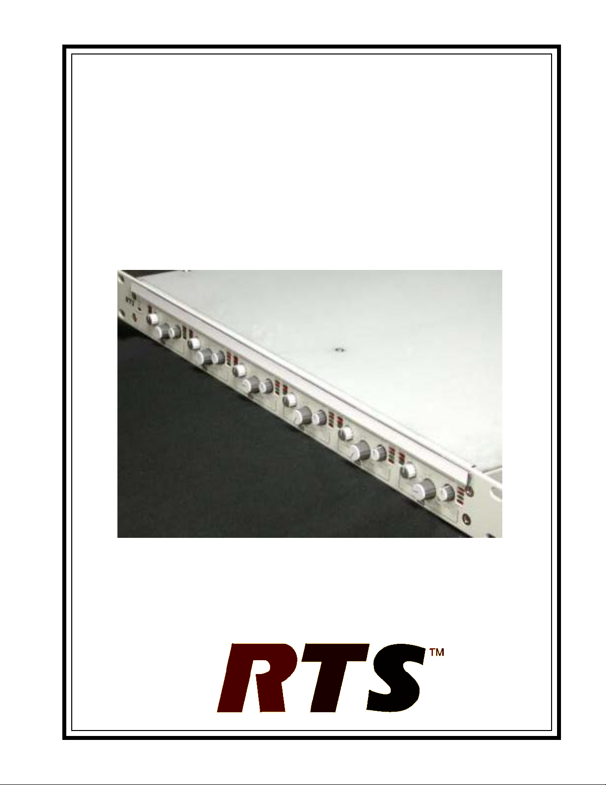
Front Panel Rear Panel
7
Page 8

Connector Specifications
.oNniP.oNniP.oNniP
1kniL1 kniL1 tuo1-HC
2kniL2 kniL2 tuo2-HC
3dnGhCklaT3 dnGhCklaT3 tuo3-HC
4)iH(hCevieceR4 )iH(hCevieceR4 tuo4-HC
5)oL(hCevieceR5 )oL(hCevieceR5 tuo5-HC
6-kniL6 kniL6 tuo6-hC
7)oL(hCklaT7 )oL(hCklaT7 CN
8)iH(hCklaT8 )iH(hCklaT8 CM-MLA
9dnghcevieceR9 dnghcevieceR9 V21)+(
)EDISW4(M9-BD)ediSxirtaM(F9-BD )tuoyllaTetaG(F51-BD
01V21)+(
11V21)+(
21V21)+(
31V21)+(
41V21)+(
51MOC-MLA
8
Page 9

Specifications
4-wire side
Connector type: DB-9 M (pin connection)
Receive Channel:
Input Gain Selector
+30/+20/+10/0/+10 dB 6 position
Input Gain Trimmer
±10dB selectable (except -)
Maximum Input Level:
+30dBu (Input protection circuit is
activated in cass of excess input)
Ouptut Gain Trimmer
±10dB adjustable
Ouput Circuit/ Impedance
Transformer balance output (600 transformer
connected)
Ground Setting
Floating (unfloating is selectable by jumper inside)
Signal Level Indicators
+10dBu (Red)
0dBu (Yellow)
-20dBu (Green)
Input Circuit / Impedance
Transformer balanced input 600 (20k
selectable)
Gate Circuit (Bypass is selectable with setting inside)
Threshold Level
-30dBu - 10dBu (selectable in front
panel by adjustable VR)
Audio Gate Attack Time
30 msec
Holding Time
3 sec (0.2.2 sec is adjustable with
VR inside)
Release Time
3 sec
Operation indication
Mute - Red LED turn OFF
VOX - Red LED turn ON
Filter Circuit
80Hz H.P. F. and 10KHz L.P.F.
Limiter Circuit
Threshold Level
+10dBu (adjustable -6dB + 12dB
via front panel trimmer VR
Gate Tally Circuit
Connector Type
DB-15F (Pin Connection)
Output signal
Open collecto output
DC 12V 50mA load operate is
possible
Mute = High (DC12V)
VOX = Low (0V)
Talk CH
Operating Output Level
0dBu (-10dBu is selectable by jumper inside)
Maximum Output Level
+10dBu (in case of adjustment 0dBu for
operating level, 600 load, 1KHz)
0 dBu (in case of adjustment -10dBu for
operating level, 600 load, 1KHz)
Matrix Side
Connector Type
DB-9F
Receive CH
Operating Output Level
0dBu
Maximum Output Level
+10dBu (in case of adjustment 0dBu for operating
level, 600 load, 1KHz)
Output Circuit/Impedance
Transformer balanced output 20
(Option: 600 balanced output by transformer
coupling)
Signal Level Indicators
+10dBu (Red)
0dBu (Yellow)
-20dBu (Red)
Talk CH
Operating Output Level
0dBu
Maximum Output Level
+20dBu
Input Circuit / Impedance
Activate balanced input 20K
(option 600 balanced input by transformer
coupling)
Ground Setting
Floating (Unfloating is selectable by jumper inside)
General
Frequency Response
Talk CH 50Hz 10kHz (-3dB)
Receive CH 80Hz 10kHz (-3dB)
Noise Level
-60dB (30.30kHz)
Distortion
0.5% (under limiter activate point)
Frequency range 100Hz 10kHz (0dBu Output)
9
Page 10

Crosstalk
-60dB (30Hz-10kHz)
-80dB (1kHz)
CMRR
-70dB (30Hz-1kHz)
-50dB (15kHz)
Activate Warr anty Temperature
0.50
Power Supply
Power Requirements
+12V 2.5A 30W
DC/DC CON ±12 V 0.45A (on board)
2PS unit for Redundant
Power Supply Indicators
Bi-color LED display. When NORMAL,
Amber color turn ON. When in Fault,
PSU-1 shows a Red LED ON, PSU-2
shows a Green LED ON.
Fault Alarm Signal Output
Contact signal (make) output to GATE
TALLY OUT
Front panel Red LED will appear.
AC Inputs
AC 100V/240V ±10%
Power Consumption
100 W
Fuse
2 A (slow blow)
Dimensions / W eight
483(w) x 400(d) x 44(h) (mm)
excl. maximum protuberance
weight = 5Kg
10
Page 11

Page 12

Page 13

-
&w4as&p
MA%-1
KUW2%lW&Cj
taws
w
Page 14

 Loading...