

Page 1
TECHNICAL MANUAL
0
MODEL
4010
Central Electronics
Includes:
Model 4001 Control Station for 4 IFB, 1 SA
Model 4001M
Model 4002 Control Station for
Model 4002M Control Station for
Model
4003
Control Station for 4 IFB, 1 SA with Microphone
8
IFB, 2 SA
8
IFB, 2 SA with Microphone
Control Station for 12 IFB, 3 SA
1
0
Model 4lW3M
Model
9300-2594-00
Rev
4020
G
6/00
3
Control Station for 12 IFB,
Portable User Statlon / Talent Electronics
SA with Microphone
RTSTM
Page 2

PROPRIETARY NOTICE
CUSTOMER SUPPORT
The RTS pmduct information and design disflosed herein
were ori~nated by and
Communications. lnc. Telex reserves all tent,
proprietary design, manufacturing, repdction, useand
sales nghts thereto, and
except to the extent rights
are
the property of Telex
to
any anicle d~sclosed thereln,
are
expressly granted to others.
COPYRIGHT NOTICE
Co fight 1994 by Telex Communications, Inc.. All
R
rig ts reserved. Reproduction in whole or in
pnor written permission from Telex is prohibited.
part
without
UNPACKING AND INSPECTION
Immediately upn recei of the equipment, inspect the
shipping contalner and
discreoancies or damage. Should there be anv. noti& the
freighi company and &e dealer at once.
5:
e contents carefully for an
,
.
WARRANTY INFORMATION
RTS products
be
Inc. to
for a period of three years
The sole obligation of Telex during the warranty period is
provide,
to
remedy covered defects appearin in products returned
pre 'd to Telex. This wananty
magnction or failure caused beyond
are
Eree
from
without
wananted by Telex Communications,
defects in materials and workmanship
from
the date of sale.
charge, parts and labor necessary to
f
oes
not cover any defect,
the
control of Telex,
Technical questions should be directed to:
Customer Service Deoartment
RTSITelex,
12000 Podand Avene South
Burnsville.
~elephone
Fax: (800) 323-0498
MN
55337 U.S.A.
(952)
884-4051
RETURN SHIPPING INSTRUCTIONS
PROCEDURE FOR RETURNS
If
a repair is necessary, contact
was pwchased.
If
re air throu
&A& ORIZATION
Customer Service Depamnent
Telex Communications, Inc.
Telephone: (877) 863-4169
Fax: (800) 323-0498
DO
NOT
THE
TO
OBTAINING A RETURN AUTHORIZATION.
Be prepared to provide the company name, address,
phone number. a penon to contact regardink the repair.
the type and
problem and ihe serial num&(s).
the dealer is not possible, obtain a
RETURN
FACTORY WITHOUT
quantity
ANY
of equipment, a
the
dealer where this unit
from:
EQUIPMENT
FIRST
description
DIRECTLY
of the
covered by this warranty.
To obtain wamnty service, follow the procedures entitled
"Procedure For Returns" and "Shipping to Manufacturer
for Repair or Adjustment".
This warranty is the sole and exclusive express warran
eiven with resuect m RTS ~roducts. It is the resmnsibi itv
6f
the user to determine betore purchase that &s produci
is suitable for the user's intended purpose.
WARRANTY.
NEITHER TELEX NOR
RTS PRODUCTS IS LIABLE FOR INCIDENTAL OR
CONSEQUENTIAL DAMAGES OF
THE
DEALER WHO SELLS
ANY
KIND.
Y
SHIPPING TO MANUFACTURER FOR REPAIR OR
ADJUSTMENT
All shipments of RTS products should be made via
United Parcel Service or the best available
pre~id. The yuifment should
I
pac ng carton,
container that is rigid and of adequate size. If a substitute
container is
moer
and sumunded with at least four inches o
kxielsior or similar shock-absorbing material. All
shi menu must
P
ude
inc
Upon completion of any re 'r
returned vla United Parcel crvice or specified shipper
collect.
the
Factoly Service Department
Telex Communicahons, Incorporated
West 1st Street
Blue
that 1s not available, use any suitable
used,
the equipment should
he
sent
Return Authorization.
Earth,
to
MN
be
shipped in e onglnal
the following address and must
56013 U.S.A.
ihe
ship,
be
wrap
ped
equipment will
.
in
be
-.
-Page
ii-
Page 3
TABLE OF CONTENTS
SECTION
1.1INTRODUCTION 1-1
1.2 USER STATION MODEL 4020
1.3CENTRALELF!CIRONICSMODEL4010
1.4 CONTROL STATION MODELS 4001.4002. 4003 14001M
1.5 SPLIITER ASSEMBLY MODELS
1.6SPECIALOPTIONS
1.7SPECmCATIONS 1-3
SECTIONTINSTAUATION
2.1 STANDARD INSTALLATION
2.2 OFTIONS INSTALLATION
SECTION
3.1INTRODUCTION 3-1
3.2 SETUP AND OPERATION OF
3.3 CONTROL STATION OPERATION MODELS 40011400lM
3.4 USER STATION OPERATION. MODEL
3.5 SUBSTITUTING
3.6 OPERATING
3.7 OPERATING DISTANCES
SE€TION4:THEORYOFOPERATION
4.1INTRODUCTMIN 4-1
4.2 OVERALL FUNCTIONAL DESCRIPTION
4.3
CENTRAL
4.4 CONTROL STATION FUNCTIONAL DESCRIPTION
4.5 USER STATION FUNCTIONAL DESCRIPTION
4.6RETURNIFBFUNCTIONALDESCRIPTION
SECTI0NS:mTNAN
5.1INTRODUCTION
5.2SERVICEINFORMATION.
5.3 GENERALMAINTENANCE
1:
NlRODU(XI0N
AND
SPECIFICATIONS
...............................
Id
.....................................................
.............................................
.......................................
.
4022
AND 4025A
4002M. 4003M
.................................
.....................
....................................................
1-1
1-1
1-2
1-2
1-2
....................................................
1.7.1 MODEL 4010 CENTRALELEClXONICS
1.7.2 MODELS 40011400lM.
W4002M.
400314003M
...............................................
..............................................
INPUT
2.1.1
2.1.2CONFlGURATIONS
WIRE
2.1.3
2.1.4 CONNECnON
2.21 SEITINGUPPRIORrIY
SEITINGUPSPEAKERMUTINGZ0NF.S
2.2.2
RElVRN
2.2.3
2.2.4 EXPANDING
2.2.5MONO
ELECTRICAL POWER (MAINS)
................................................
AND CABLE CONSIDERATIONS
TO
EXISTING MICROPHONES.
...............................................
.............................................
IF'B
INSTALLATIONS
THE
CONTROL STATI0N"S
IFB
.....................................................
J:
OPERATING INSTRUCTIONS
.........................................
......................................
....................................
...............................
....................................
....................................
"TW"
TYPE
USER STATIONS
&
OTHER
SOURCES . 2-1
...................................
ALL
FUNCTION
........................
1-3
1-3
21
2-1
2-1
2-1
2-1
2-1
2-2
2-2
2-2
2-2
2-2
3-1
.....................................................
"TW"
INTWCOM STATIONS
WITH
TELCO DRY PAIR@)
................................................
THE
CENTRAL
4020
ELEClXONICS. MODEL 4010
.
4fM2I4OOZM
.
400314003M
.....................................
FOR
IFB
USER STATIONS
..................
..............
....................
.......................................
........................................
3-1
3-1
3-1
3-1
3-2
3-2
4-1
.....................................................
.......................................
ELF!CIRONICS FUNCTIONAL DESCRIPTION
.............................
.................................
....................................
.....................................
CE
...............................................
.....................................................
...............................................
...............................................
5.3.1
INPUT
5.3.2CLEANING 5-1
5.3.3 NSEREPLACEMENT
POWER SELECTION
...........................................
....................................................
..............................................
4-1
4-1
4-3
4-4
4-4
5-1
5-1
5-1
5-1
5-1
5-1
-Page
iii-
Page 4
TABLE
OF CONTENTS
(Continued)
r
l
5AF'EwoRMANCE~
5.4.1 MODEL 4010 TEST PROCEDURE
5.4.2 MODEL 4001 CONTROL STATION MIC PRETEST PROCEDURE 5-5
5.4.3 MODEL 4001
5.4.4 MODEL
5.45 MODEL 4003
5.4.6 MODEL 4020 USER STATION
5.5TROUBLESHOOTlNG
SECITON
6.1INTRODUCnON
6.2 HOW
6.3 SHIPPING LIST MODEL
6.4 SHIPPING
6.5 SHIPPING
6.6 SHIPPING
APPENDMA
APPENDMB
NOTES
SECFION7:DIAGRAMS
6:
M
FINALASSEMBLY.MODEL4001-9010-24W3-0.
6.3.1
6.3.2
PRINTED
6.3.3 FRONT PANEL, MODEL 4001
6.3.3.1 FRONT PANEL, MODEL 4001M GOOSENECK - 9070-2360-00 6-3
6.4.1 FINAL ASSEMBLY, MODEL 4002-9010-2011-00
6.4.2 PRINTED
6.4.3
PRINTED
6.45 FRONT PANEL, MODEL 4002 - 9070-2014-00 6-5
6.45.1 FRONT PANEL. MODEL
65.1 FINAL ASSEMBLY. MODEL 4003 - 9010-201-
6.5.2 PRINTED
6.5.3
PRINTED
6.5.4 FRONT PANEL. MODEL 4003 - 9070-2022M)
6.5.4.1 FRONT PANEL, MODEL 4003M GOOSENECK - 9070-2364- 6-7
6.5.5 SHIPPING
6.5.6 FINAL ASSEMBLY, MODEL4010-9010-213&0O
6.5.7 BACK PANEL ASSEMBLY, MODEL 4010 -9020-213POO
PRINTED
6.5.8
6.5.9 FRONT PANEL, MODEL4010 -9070-1977-
6.6.1 FINAL ASSEMBLY. MODEL
6.6.2 BACK PANEL ASSEMBLY. MODEL
6.6.3 PRINTED
.............................................................
IFB
CONTROL STATION
4002
IFB
CONTROL STATION
IFB
CONTROL STATION
LISTS
OF
.....................................................
OBTAIN PARTS
CIRCUIT
LIST,
MODEL
CIRCUIT
CIRCUIT
LIST,
MODEL 4003 - KlOO-236360 6-5
CIRCUIT
CIRCUIT ASSY,
UST.
CIRCUIT
LIST,
MODEL 4020 - KlOO-23684
CIRCUIT
.........................................................
.........................................................
................................................
..........................................
........................
TEST
TEST
PROCEDURE
TEST PROCEDURE
TEST
PROCEDURE
PROCEDURE
................................
...........................
...........................
...........................
..................................................
REPLACEABLE
PARTS
....................................
................................................
4001
-
KlOO-2359M)
....................................
.............................
ASSY. MODEL 4001, MIC PRE BOARD. CC4000 - 9030-1999-W
-
9070-200600
................................
..........
...................
4002
-
KlOO-2361M)
....................................
..............................
ASSY. MODEL
ASSY, MODEL
4002.
MIC
PRE BOARD, CC4000 - 9030-1999-00
4002.
SWITCH BOARD - 9030-4376-00
..........
...............
................................
4002M
GOOSENECK - 9070-236143 6-5
...................
....................................
..............................
ASSY, MODEL 4003 . MIC
MODEL
4003.
PRE
SWITCH
BOARD,
BOARD.
(3(34000
CC~OOO
-
-
9030-1999-0
90~3n-00
..........
..........
................................
...................
MODEL 4010 - WXL2365-0
ASSEMBLY. MODEL 4010. CC4010 - 9030-1974-00
................................
..............................
.........................
.................
................................
....................................
4020
-
9010-1927M)
4020
-
ASSEMBLY. MODEL 4020 - 9030-1904-00
..............................
9020-1926-00
.........................
......................
.................................................
55
5-5
5-6
5-6
5-7
5-8
5-8
6-1
6-1
6-1
6-1
6-1
6-2
6-3
6-3
6-3
6-4
6-5
66
6-6
6-7
6=1
6-8
6-8
6-8
6-9
6-11
6-11
6-12
6-12
6-12
A-1
El
N-1
7-1
a
Page 5
SECITON
SPECIFiCATIONS
1:
INTRODUCTION
AND
13
CENTRAL
ELECTRONICS MODEL4010
l.l
INTRODUCTION
This
IFB
System
wmmunications system (a program mterrupt system)
created especially
television broadcast industry,
recarded media applications. The system
User Stations Central Electronics and Control Panels. A
modular approach
each installation.
aadindalwmpon~nts mi be add&
typical system
Control Panels, one Central Electronics unit, four User
Stations, and assorted cabling and interconnect
maximum standard wnfiguration
Panels, three Central Electronics, and twelve User
Stations.
l.2
USER STATION MODEL
The User Station, a small "belt pack" package, allows the
talent to
Central Electronics and the Control Stations and may be
worn
sportscasters, etc. Behind-the-scenes pemnnel may
find the
wntrol. These may be production assistants, audio boom
operators, stage monitor mixers, "on stage" producers,
Each
orovide a stereo audio siensl to the user.
&npliirs rated at
set of headohones or loudsoeakers.
conveniently extended to hressing rooks or other off-
camera
The line input to the belt pack
Electronics unit. This signal contains the audio
information
the belt pack. Both the left and right signals are wried
on a standard two-eonductor microphone cable. The left
channel is designated
noninterruptible. Separate
and stereo headphones. Individual left and right volume
controls on the belt pack enable the user to adjust
listening levels for personal wmfort. When mono
headphones
program
A
standard
with this system and may be used
4MO
*"IFBm
and "foldback".
receive
by
IFB
belt pack contains the necessary electronics to
areas
-
User Station if necessary.
is
also
is
a one-way Interruptible
to
meet the critical requirements of the
as
assures
Should svstem exnansion
may
the audio signals designated
talent, such
the optimum configuration for
consist of the following: up to four
4020
as
newscasters, musicians,
well
allows
FeedBacka
as
other live or
is
composed of
be
desired.
as
necessary.
units.
four Control
The
by
also
feeds usehl for production coordination and
Two
paver
In
waneach are
where communications is desirable.
as
well
as
the
DC
as
interruptible, the right channel,
jacks
are
used, they
interrupted program audio.
TW
Intercom belt pack is
known
as
are
"IRF,
ca
able of dhg any
TR
us
the
IFB
can
is
driven from the Central
voltage ne- to power
are
provided for mono
fed only the left channel
fully
compatible
in
place of the Model
Interrupted Return Feed"
A
the
etc.
be
The Central Electronics unit contains all the necessary
wntrol functions and electronics to provide the active
between the Control Station
accepts three program inputs, four microphone inputs
and switch keying signal inputs from up
Stations. In addition, it supplies composite output feeds to
the User Station belt
Stage Announce (SA) ampuer, relay contacts
monitor muting, and interwnnection
Stations.
The three bridging program inputs
vanel terminal strirj. These simals
b
eight
of the three ro
level wntrofl =tput of
driver amplifier
This
output.
right channel line input. For the
output of the level control
then to a summing amplifier. The summing amplifier
drives a power output stage which adds the audio
29
volt
a
left channel line input.
the
in
be
assigned the
internal
have the interrupt signal in both
headphones.
SA
The
three program signals to the SA Output connector.
This
SA Output
Station feed, except
floatin transformer-balanced. This output may be
amp
hf!
'
mom speaker or some other area The program signal
assigned to the SA output
micro
ol
a pr
pmgram level control
only the microphone signal
When the SA function
activated inside the Central
appear on the
connected to a control room monitor amplifier input.
They
prevent feedback when the SA
internal programming jumpers
allow two separate
booth Control Station SA function may be engaged,
muting that local speaker only, and not aaecting the
production control room speaker.
uninterrupted signal
DC
potential.
left channel only. H-er, the right channel may
circuit
(Stage Announce)*
ed and fed to a stage announce speaker, dressing
hone signal from any of the control panels. Should
uction not require a program feed to the
can
be
used to mute the local monitor speaker and
packs,
selector-k4tches
sources
which
sends
This
This
same
s@al
board santch. The
is
similar to the left channel of a User
it
does not
may
rear
panel terminal
areas
and
the
User
to
four Control
line-level
to the
this
audii
is
fed to an
audio feeds the User Station
allows for pmgram interrupt
as
feature
can
be turned off, in which
is
heard.
is
used,
Electronics.
of speaker muting, e.g., the audio
audio
feeds
to
the Control
are
available on a
are
attenuated and fed
that
assign any one
lespective
level control
to
the
feeds
interrupted channel, the
front-panel
noninterrupted
the User Station
electronic
the
left
channel via an
User
Station may now
ears
when
using
routes any of the
carry
dc
and it
be interrupted
one or
is
may
two
Tkeir contacts
strip
and
in
use.
In addition,
be configured
link
Station. It
to
the
for
rear-
is
fed to a
switch
signal to
stereo
is
fully
by
stage,
the
case
relays
are
can
be
a
to
Page
1-1
Page 6
*"SAU
Address
selectable monitoring of any input or output signal via a
st-
sffa only the monitor circuits and do not interfere with
other functions.
Inside the Model 4010, a single large circuit board is used
to mount all electronic wmponents.
terminal strip provides connections for the program
inputs,
Connection between the Control Stations and the Central
Electronics
connector.
1.4
4001,4802,4003
The Control Station
equipment rack. It provides a given number of switch
functions
offers
IFB
supplk
Each
This refers to a gooseneck micro hone attached to the
panel. Should an existing microp
is
also known
A
frontpanel monitor section allows for
phone
jack.
IFB
outputs, SA output, and relay contacts.
is
made through a 50-pin miaoribbon
CONTROL STATION MODELS
accordin
IFB
1
thru
1
thm
IFB
8,
IFB
1
thru
model number may
for operations, a connection on the Control Station
microphone preamp circuit
microphone-level or line-level signal from that
microphone.
as
Studio Announce or Studio
A
volume
1
WlM,
is
to the model number. The 4001
dB
IFB
12,
control and a selector switch
A
-2M,
designed to mount in a comb or
4,
IFE
ALL,
IFB
be
4003M
ALL
and SA. The 4002 has
SA 1 and SA
ALL.,
SA
ordered with an "M" suffix.
R
one
board
may be used to accept a
2.
Model 4003
1,
SA 2 and SA 3.
be
more suitable
rear-panel
The Model
paralleling two female connectors to co~ect
controls\ stations
The Model
four female mmectors for
stations.
snap-on cover housing.
1.6
SPECIAL OFTIONS
A
return-send function may
small
modifications.
User Station
via a closed-circuit bop.
by
switching in
feed to that station.
Electronics
which
connect to a 9-pin
rear panel.
transfer the announar's microphone from the propam
line to a monitor
room. The person at t
the announcer without having the signal go over the
4022
4WA
AU
connectors
to
turn
This
features a single male connector
two
to
the central electronics
features a
This
communicate with the Control Stations
an
extra load, usually a lamp,
on relay-driving
allows
am
f
single
male
connector
use
with
up
to
four
are
held searely in place
be
incorporated
feature
This
Sensor
miniature
an external relay to
litier
e control station may now listen to
allows the talent at the
is
done
at
the User Ststion
ckmits
circuits,
or intercom in the control
in the Central
the outputs of
D
mnnector on the
control
with
agoas
be
used
with
with
some
the
air.
to
a
Each
Control Station is connected to the Central
via
Ele~troniCS
cable
with microribbon connectors.
Stations converge at the 4025 and a single cable then
connects to the 4010.
Model 4001 Control Stations to be connected to a single
Central Electronics unit. When
Electronics units are ud in an eight output
con£iguration, the Model 4002 controls all outputs from
up to four locations. Similarly, three Model 4010's and
twelve outputs
up to four locations. Priority of Control Station switch
signals is pmgrammable and may be
installation. The system may be used without priority
switching if desired.
1.5
SPLCITERASSEMBLY
MODELS
The splitter assemblies connect the control stations with
the central electronics ria 25-pair cable with microribbon
connectors.
a Model 4025 Splitter and 50-conductor
An
the Control
This
configuration allows up to four
two
Model 4010 Central
are
controlled with a Model 4003,
set
at the time of
4022
And
4025A
also
in
Page 1-2
Page 7
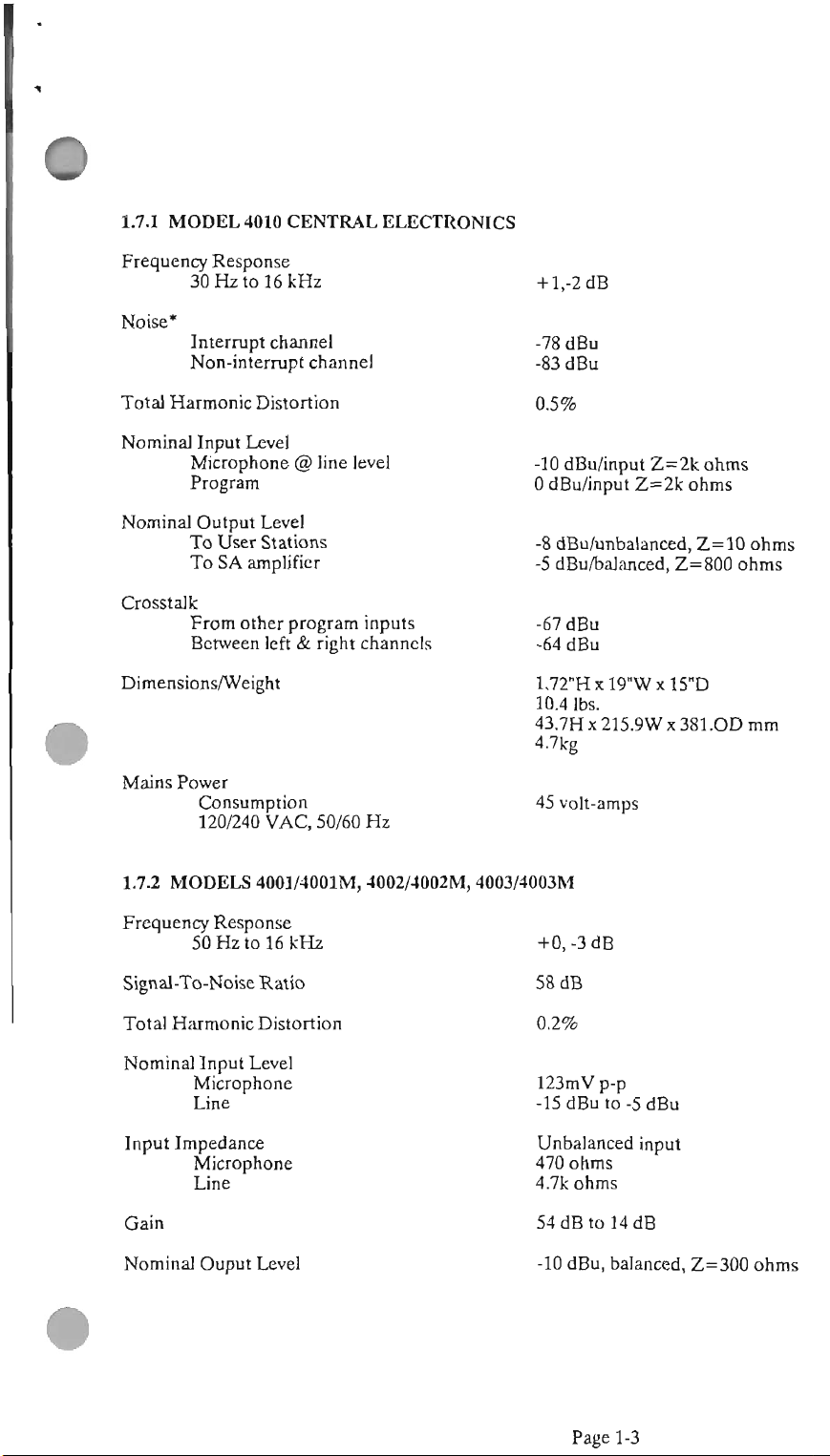
W.1 MODEL 4010
CENTRAL
Frequency Response
30 Hz
to
16 kHz
Nok*
Interrupt channel
Non-intempt channel
Total Harmonic Distortion
Nominal Input Level
@
Miaophone
line level
Program
Nominal Output Level
User
SA
amplifier
Stations
To
To
Crosstalk
Fmm other program inputs
&
Between left
right channels
ELECTRONICS
-10
dBdinput
0
dBu/input
-8
dBuhnbalanced,
-5
dBu/balanced,
Z=2k
Z=2k
ohms
2=800
ohms
Z=10
ohms
ohms
Mains
Power
45
Consumption
1201240
1.7.2 MODELS 4001/4001M, 4002/4002M, 4003l4003M
VAC
50/60 Hz
volt-amps
Frequency Response
5OHzto16lcHz
Signal-To-Noise Ratio
Total Harmonic Distortion
Nominal Input Level
Microphone
Line
Input Impedance
Microphone
Line
123mV
-15
dBu to
Unbalanced input
470
4.711
Gain
-10
Nominal Ouput Level
dBu, balanced,
p-p
ohms
ohms
-5
dBu
Z=UM
ohms
Page
1-3
Page 8
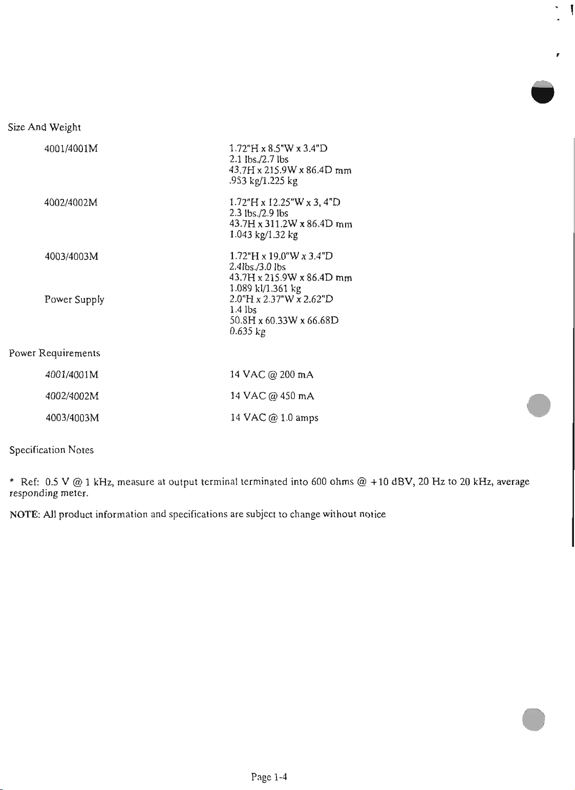
Size And Weight
4001/4001M
4003/4003M
Power Supply
Power Requirements
4001/4001M
14 VAC
@
200
mA
4002/4WZM
4003I4003M
Specification Notes
*
Ref: 05 V @ 1
responding meter.
NOTE:
AU
product information and specifications
14 VAC @ 450
14 VAC @ 1.0
kHz,
measure at output terminal terminated into
are
subject to change without notice
mA
amp
600
ohms @ +10 dBV, 20
Hz
to
20
kHz,
average
Page 1-4
Page 9
SECTION
2.1
The Central
mounted unit.
sopported
dimensions and outline
of the
of
this
provides a rear panel terminal
the Model
impedance, line-level
standard microphone cable. or telw cable.
Station
(2500
adapter,
(5WO
and Program Inputs, may be made at
2:
INSTALLATION
STANDARD INSTALLATION
Mth the
Snies
El&&,
me
4000
mu
IFB
Model 4010,
of
the
Model
provided.
dra*
for all wmponents
is
4010 must
htallation
System are located at the end
manual. The Central Electronics, Model 4010,
strip
for connection to
4020
User Stations.
signal
This
is
and may be sent
The
will
work
at distances of up to
feet)
with
#22
cable. With an optional battery
this
range
can
be
feet). Connections for
extended
SA
Output,
to
1500
this
760
SA
terminal
a rack
be
a
low-
over
User
meters
meters
relays,
strip.
use
The Control Stations
either individual or common
local AC power supplies. This allows the interconnect
2.12
CONFIGURATIONS
cables (to
carrying
might
supply provides power for
switch
2.1.1
The standard Model4010
designed to operate on
50or60Hz
operate at % volts
volt model operates on
Hz
10%,50
require 1214 volts ac or 16-20 volts de. A
mounted power module
ac at
or transformer capable of supplying
TheoptputmanedstoTB2,tenninals3and4onthc
the
Central Eledronics) to
only,
bring
lamp.
INPUT
avoiding
the entire
ELECCRICAL
the
chance
system
120
that
down
This
the
electronics and
POWER
IFB
central ekt~onies
volts
ac
Thew-100voltmodelisdesignedto
ac
10%,50 or
220
60
volts ac 10%- 50 or
The 240-volt model operates on
or
60
Hz
1
amp
The series
is
provided for
with
4000
an output of S14 volts
this.
Any external supply
this
remain
signal-
a shorted cable
local
power
the
(MAINS)
10% at either
Hz
The
220-
60
240
volts
ac
control stations
wall
may be
nsul.
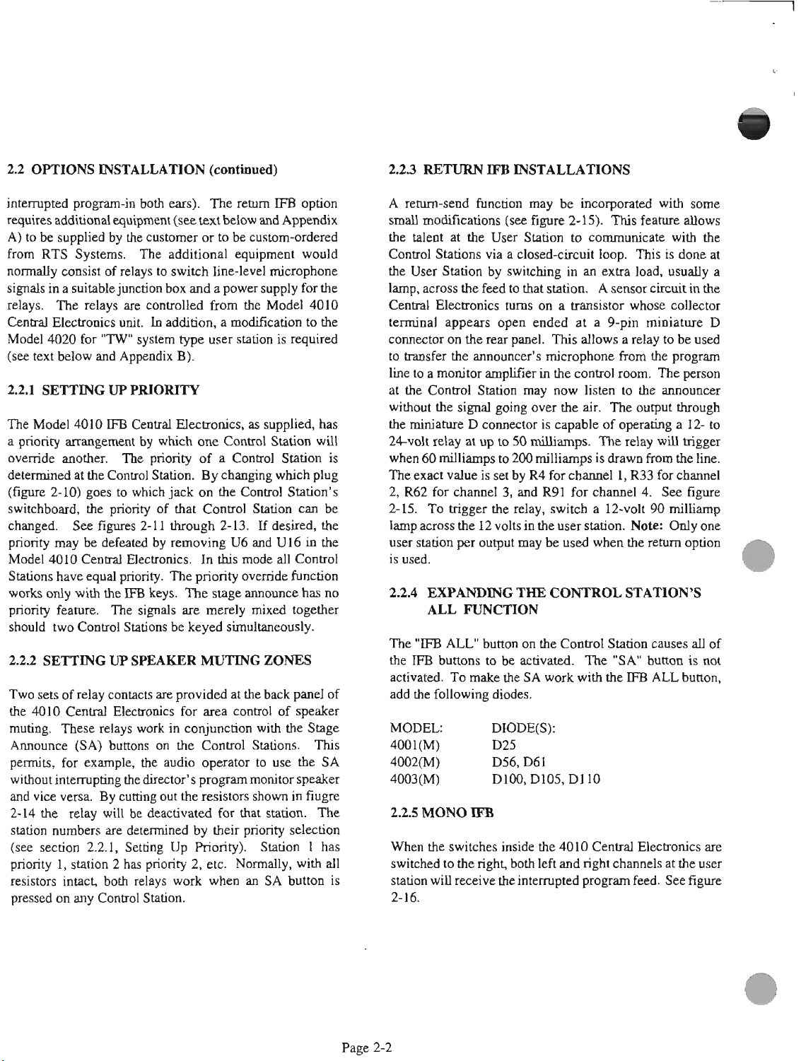
microphone preamplifier board of the control station.
See
figure 2-1.
signal
an average
The
program inputs accept balanced lines
level of about
signal level of +4 to +8 dBu. See figure
-5
dBa
See figure
with
26.
26.
is
a
A
standard interrupted feedback system
one Model 4010 Central Elwtronics, four Model
User Stations, one Model
4025
Splitter Assembly, and
at least one Model 4001 Control Station.
four Control Stations may
2.13
WIRE
AND
CABLE
be
used. See figure
CONSIDERATIONS
can
wnsist of
As
4020
many
22
as
The Control Stations are connected to the Central
Electronics with 50-conductor ribbon cables, Model
4015-MI.
The
MI
is
the cable length in feet. These
cables may be ordered in 5-foot increments from
feet to 100 feet. The maximum recomended cable
length
is
100 feet from any Control Station to the
Central Electronics. The user stations are wmected
to the Central Electrodtes through standard
two-
wnductor-plus-shield microphone cable (e.g. Belden
A
#9451).
rear-panel terminal strip.
The Stage Announce output
Smith #5209 spadelug attaches to the
See
figure
2-5.
is
balanced and provides
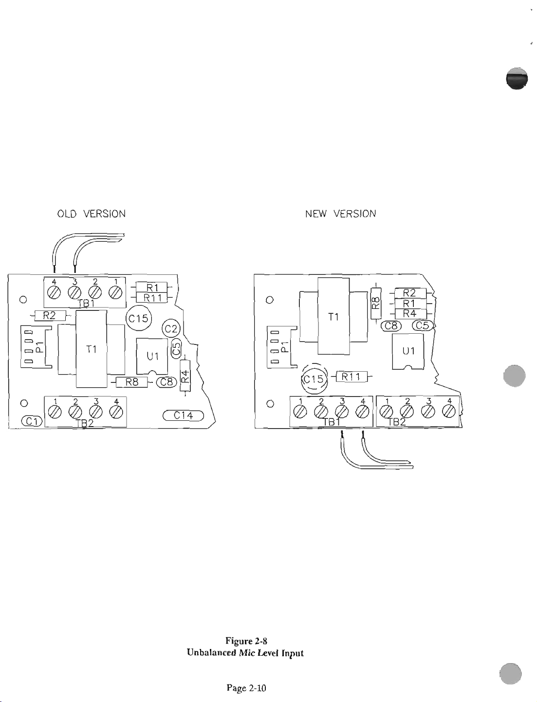
2.lA
CONNECllON
PHONES,
OTHER
Any series
1W"
SOURCES
4000
existing microphones
type.
user
stationsA
use.themicrophoneinanexistitlgTW"typcuser
station. Conned the UnSwitched
from
the
TW"
the Control Station.
to a Model 801 Master station, see Appendix C.
5
The
design of the Series
field installaton and adjustment of
features
diseussed
TO
EMSTING
TYPE
USER
STATIONS AND
Control Station
(figures
series
2-7
4000
MICRO-
can
be
conneded to
and 28) and
Control
Mic
Station
output (USM)
user station to the line-level input on
See
figure
29.
For connections
4MW)
IFB
system ped easy
the
options and
below. Options/featuns indude
priority controt speaker muting mnes or areas, return
IFB,
expansion of the
andselection of monaural
IFB
"ALL"
IFB
(same signal-the
TW"
can
function
Page 10
22
OPnoNS INSTALLATION
(mtfaued)
RETURN
IFB
INSTALLATIONS
intmpted program-in
rrpuires
A)tobesuppliedby thecuaomcrortobecustom~
from RTS Systems. The additional equipment
normally consist
signals in a soitable junction box
relays. The relays
Central
Model
(see
The Model 4010
a
override another.
aetermined
(figure
switchboatd, the priority
cbanged See
prioritymay
Model
Statim have
additional
Electronics
4020
for
text
below
and
priority arraagemnt
at
the
2-10) go- to which
bedefeatadby1wnovingU6andU16inthe
4010
Central
equal
worLsonlywiththeIFBkeys.
priority fm. The signals
should
Two
the
muting.
Announce (SA)
penuits,
without intermptiag
and
priority 1, station 2
resistors intact,
two
Contml Stations be
sap
of
relay
4010
central
These relays work in conjunction with
for example,
vice versa By
2-14
the
relay
station numbers
(see
section 2.2.1, Setting Up Riority). Station
pressed
on any control station.
both
em).
The
rrtllm
IFB
equipment
of
relays to
are
unit.
"IW"
Appeadix
IFB
The
Conml
fipm
Electronics.
priority. The priority ovenide function
mulcts
Elecaonics for
buaons
the
cutting
wilt
be
are
dmrmined
has
both
(see
mtbdow
switch
coatrolled
In
addition. a modi6cation to
system
Central
by
which
priority
Station By changiug
jack
of
2-11 through 2-13.
he-level microphone
and
a
from
type
user
B).
Electronics,
one
of
on
that
Control Station
In
Thestageann-hasno
are
merely mixed t0gek-x
keyed
are
provided
area
on the Couhul Sta6m. Tbis
the
audio oparator to
director's pmgrammonitor
out the
resistors
deactivated
by their priority selection
priority 2, etc. Normally, with
relays
work
when
and
Appendix
power
supply for the
the Model 4010
station
is
as
supplied,
Contml
a Control Station
the Control Station's
this mode all Control
sim-usly.
MW
which
If
desind,
at
the
back
contrd of
the
use
shown in
for
that
station.
an
SA button
option
wdd
the
required
has
will
is
plug
can
be
the
panel
of
speaker
Stage
the
SA
speaker
fiugre
The
1
has
all
is
A~-&fuMionmayk~withgomt
smaU
modiiicatious
the talmt
Control
the User
at
Stations via
Station
lamp,acrossthefeedtothatmtion.
Cmtral
terminal
connector on
to transfer the anmumds miaophone
Electnmica
appears open ended at a 9-pin miniature D
lhetoadtoramplihainthecontrolrwm.
at
the
Control Station may now
without
the
%volt relay
the signal going over the
miniature
~JJC
User Station
by
the
mar
D
wmecbx
at
up
to
(sea
figm
2-15).
a closed-circuit loop.
switching in
tums
on a
panel.
This
is
capable of operatiag a 12- to
SO
mibmpa
This
to
communicate
an
exm
Asglsmcircuitinthe
trsnsistor
allows a relay to be
listen
air.
The output through
The
feat1118
This
load,
whose collecbx
from
to the anno-
relay
allows
witb
is
done
usually a
the program
Thepason
will
uigger
the
at
used
when60~touX)~isdrawnfromtheline.
Thew;actvnlueissetbyR4forchannel1,R33
2, R62 for
2-15. To
channel
hi-
3,
and
R91
for
channel 4.
the hay, switch a 12-volt
iampacrossthe12voltsintheasastation
user station
is
used.
22A
per
output may be
EXPANDING
ALL
FUNCTION
THE
CONTROL
used
when
forcbanuel
See
figwe
90
milliamp
Note:
Odyone
the
return
option
STATION'S
The"IFBW"bumooontheControlstationcausesallof
theIFBbuttonstobeactivated. The"SAnbuaonis~
activattd
add
MODEL: DIODWS):
40010 D25
4002(M)
40030 D100, D105, Dl10
When
switched to the
station wiU receive
2-
16.
TomaketheSAw&withthePBWbuttoa
the following
the
switches
diodes.
D56, D61
inside
right
both I&
thehtemqtd
the 4010
and
Central
right
program feed.
Electronics
charnels
at
the
Sea
are
user
figure
Page 2-2
Page 11
OLD VERSION
NEW VERSION
Power
Connection
FROM POWER MODULE
OR ALTERNATE SOURCE
Figure
To
2-1
Series
4000
Control
Stations
_(
Page 12
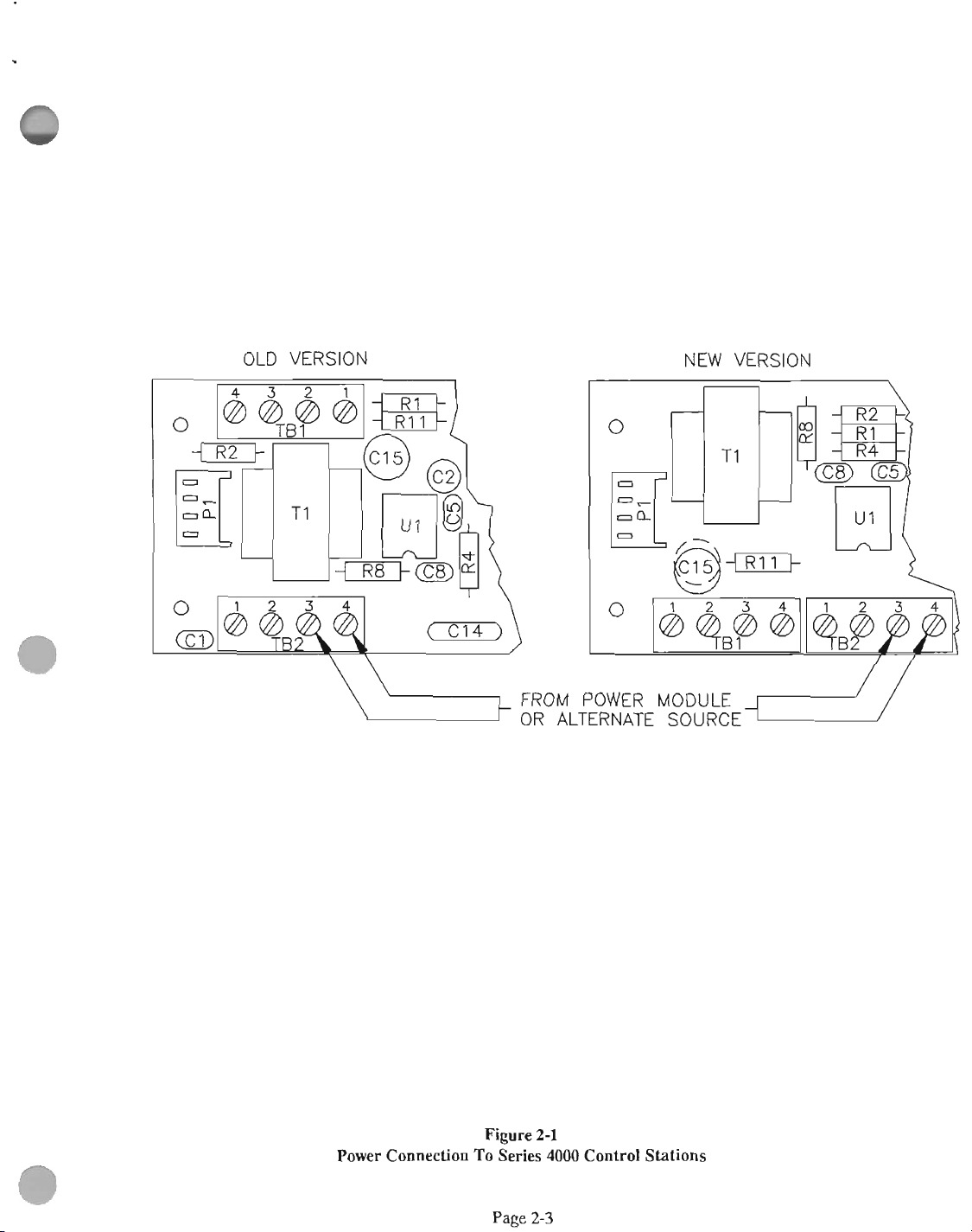
The
system
emblies
may
be
expanded
and
four Control Stations. See
for up
to
twelve.
figures
User
23
Stations,
and
2-4.
Page
2-4
three
Central
Electronics, three
Splitter
Ass-
Page 13
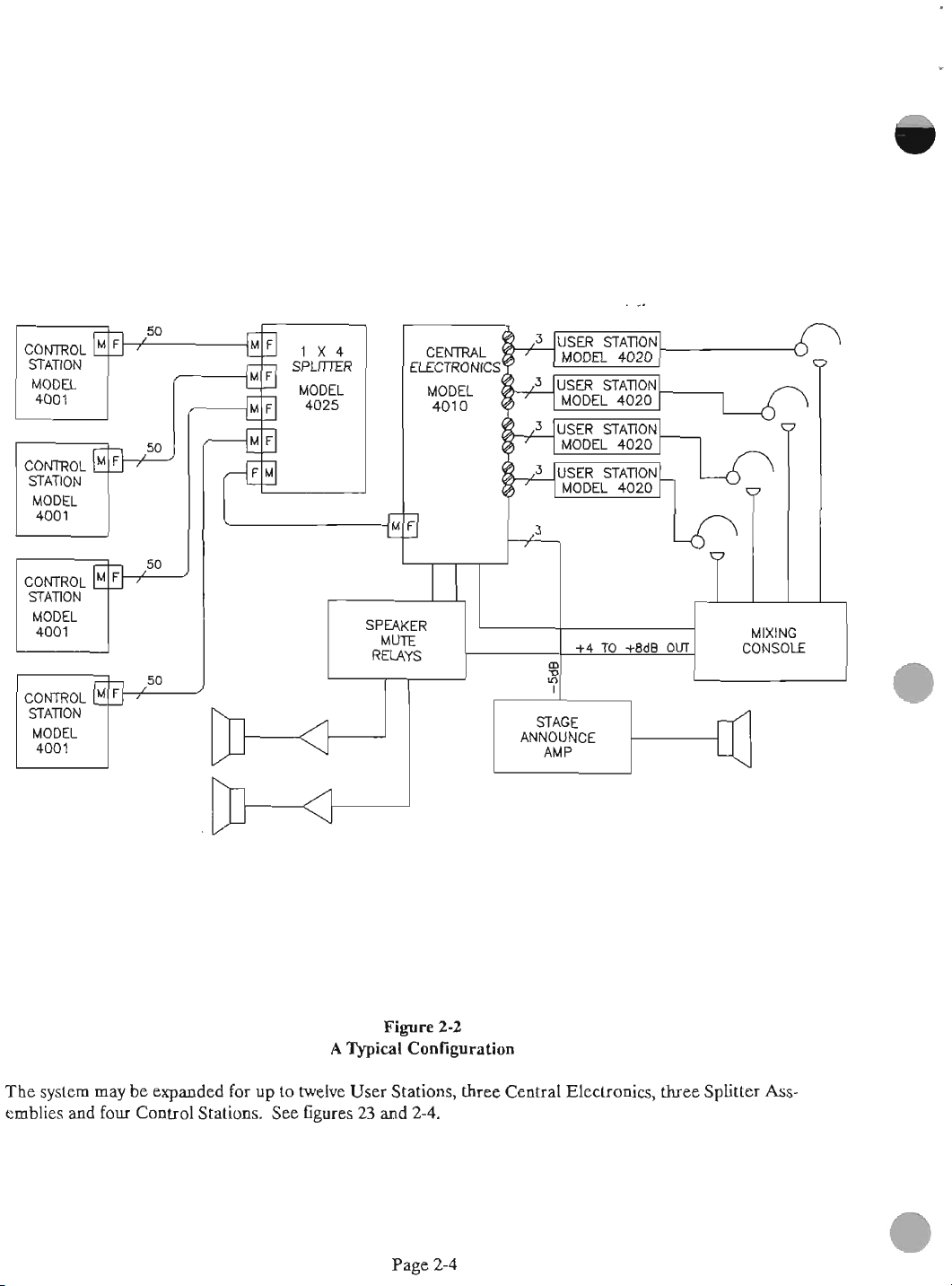
CONTROL
STATION
mq
STATION
CONlROL
STATION
1x4
SPUmR
MODEL
4025
Fire
A
ConGgumtion-2
Page
2-3
System
2-5
Page 14
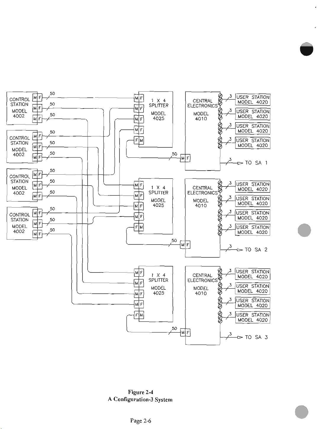
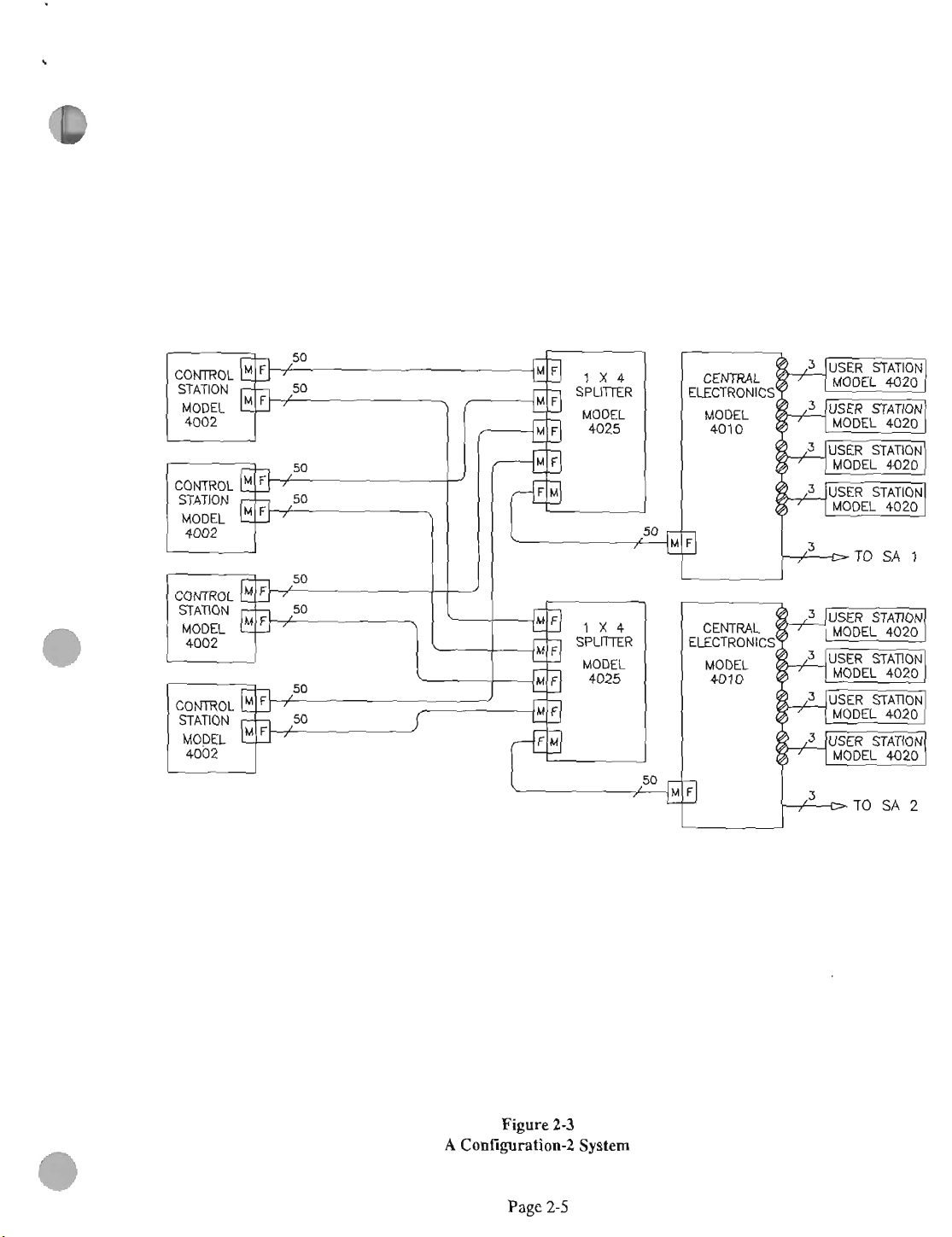
Figore
A
Contiguration-3
2-4
System
Page 15
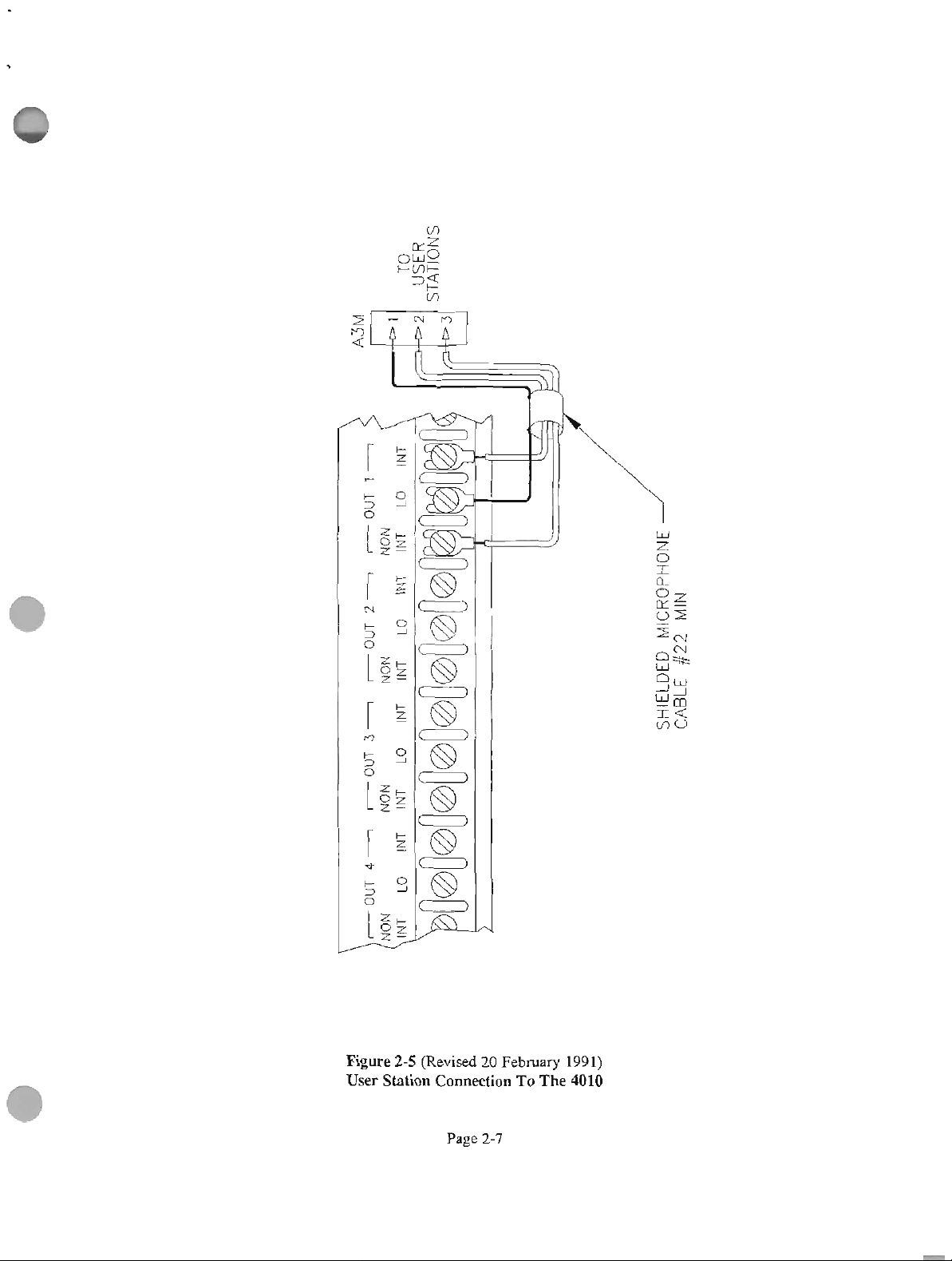
S
ON
TO
USER
STAT1
INT
11
LO
-OUT
21
LO INT INT
INT
-0UT3- -OUT
NoN NoN NoN
INT INT LO INT
41
LO
INT
TOUT
INON
MIN
#22
CABLE
SHIELDED MICROPHONE
Page 16
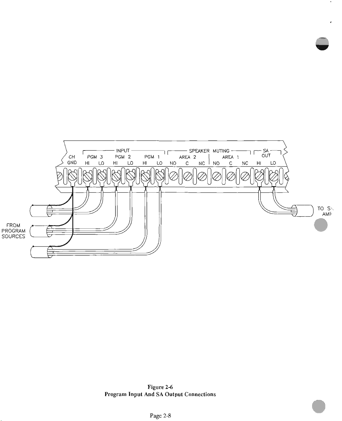
FROM
PROGRAM
SOURCES
TO
Si
Pmgram
Input
Figure
And
Page
SA
2-8
24
Output
Connections
Page 17
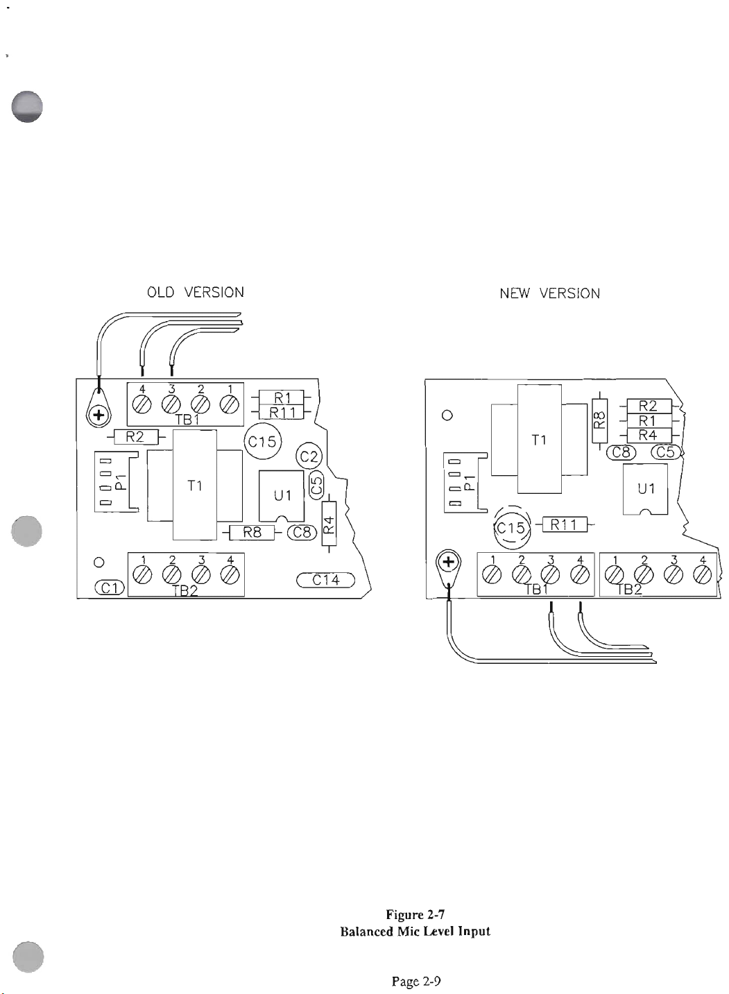
OLD VERSION
NEW VERSION
Balanced
Figwe
Mic
2-7
Lavel
Input
Page 18
OLD VERSION
NEW VERSION
Page
2-10
Page 19
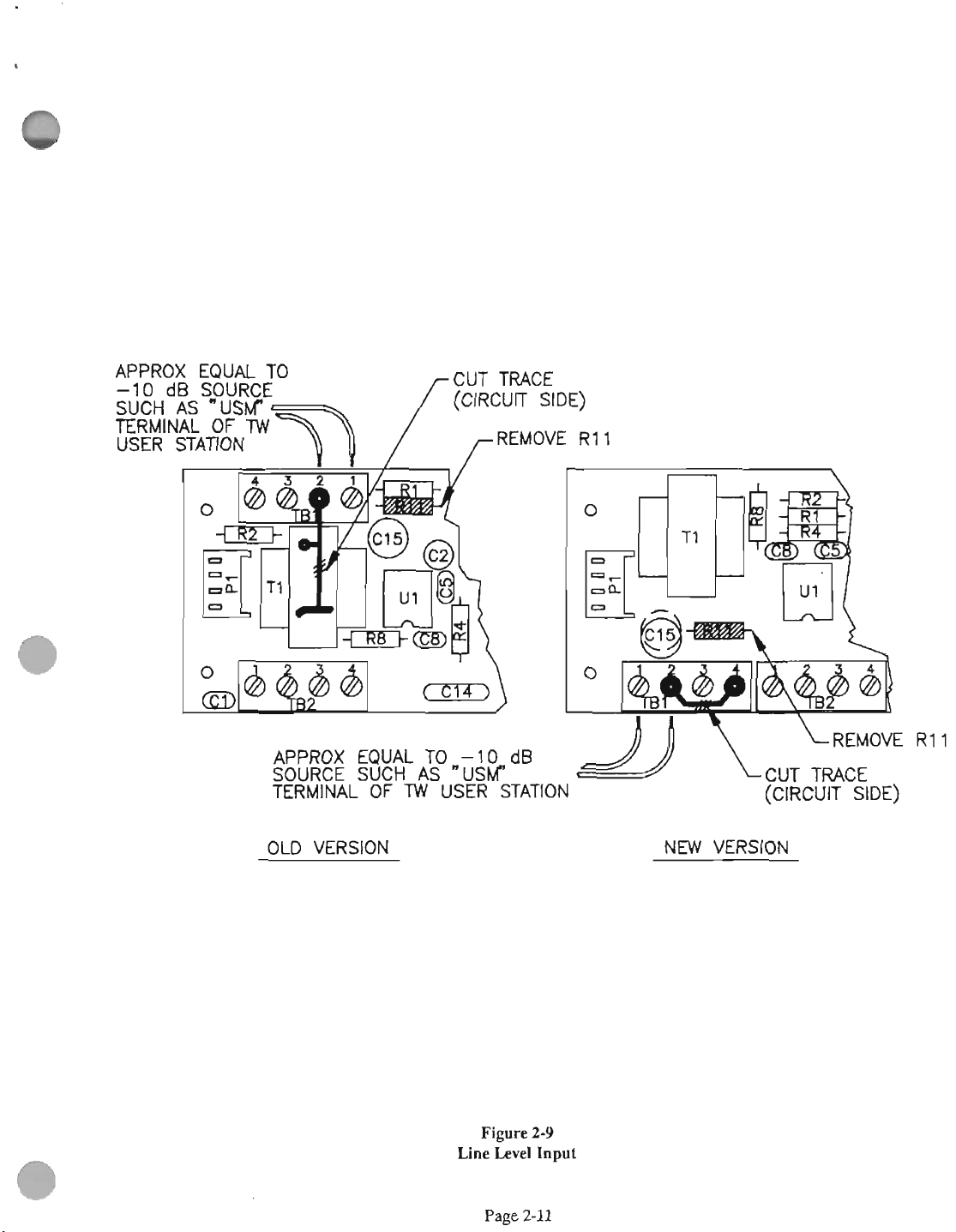
APPROX EQUAL TO
SOURCE SUCH
TERMINAL OF
AS
MI
-1
0
dB
"USW
USER STATION
(ClRCUrf SIDE)
OLD VERSION
Figurn
Une
LeveI
NEW MRSION
2-9
Input
Page 20
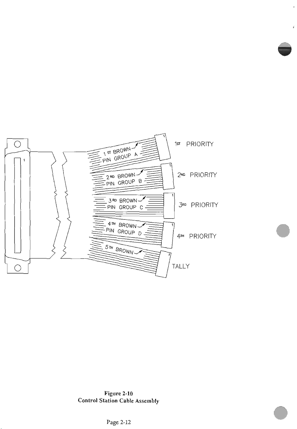
Control
Figwe
Station
Page
2-10
Cable
2-12
Assembly
Page 21
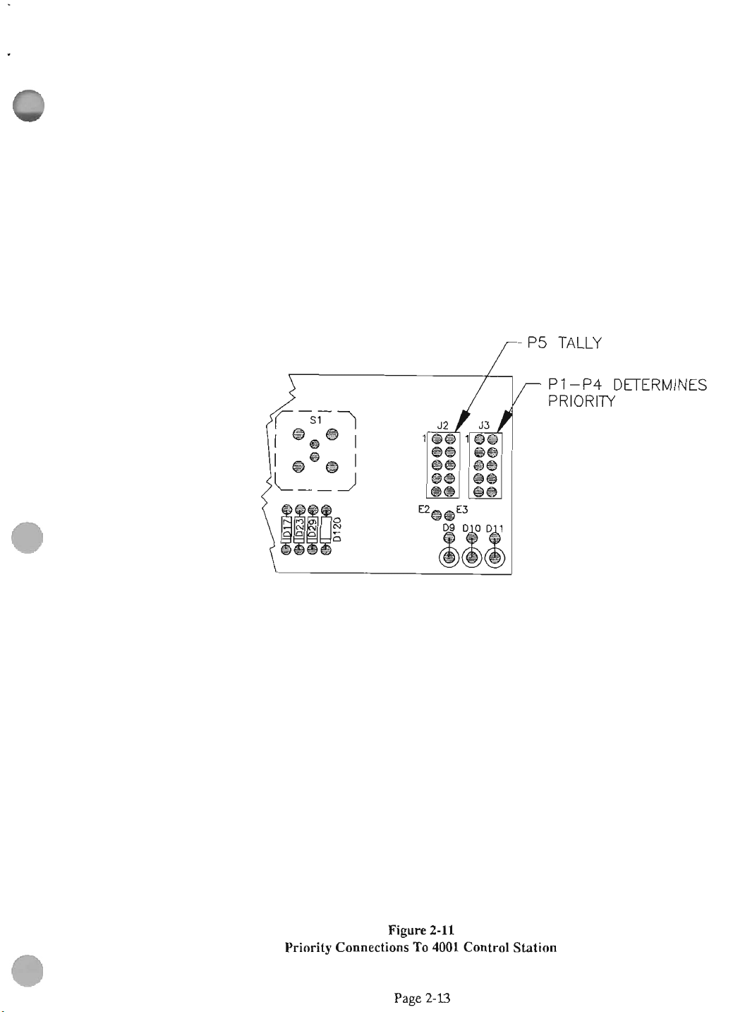
PI
-P4 DETERMINES
PRIORITY
Wpm
Priority Connections To
2-11
4001
Control Station
Page 22
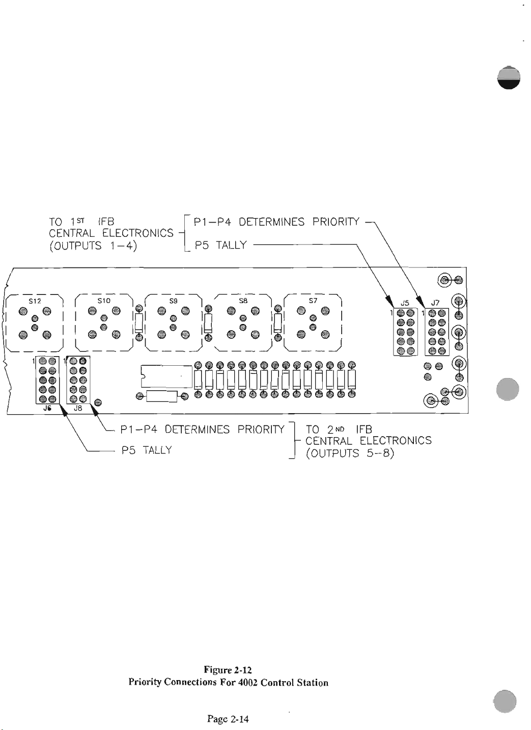
TO
1s
IFB PI -P4 DETERMINES PRIORIN
CENTRAL ELECTRONICS
(OUTPUTS 1-4)
\-
P1 -P4 DETERMINES PRIORITY
P5 TAUY (OUTPUTS 5-8)
{
P5 TALLY
CENTRAL ELECTRONICS
Priority
Figure
ConnceUons
For
Page
2-I2
4002
2-14
Control
Station
Page 23
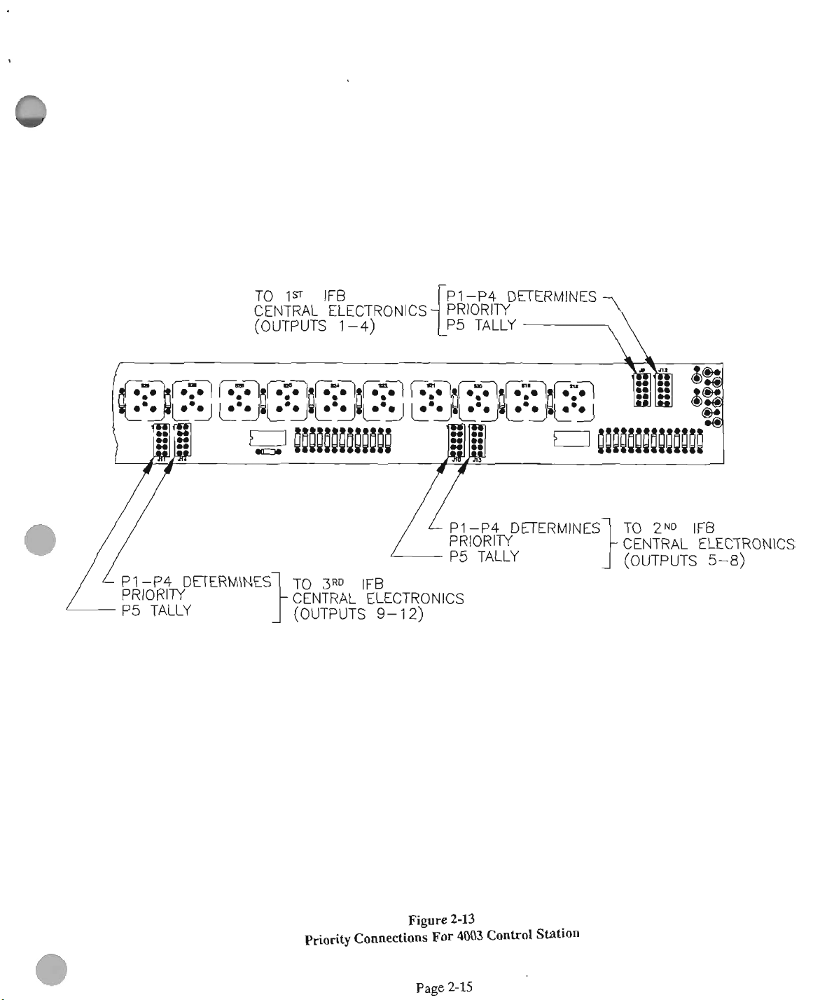
TO
1ST
IFB
CENTRAL ELECTRONICS
(OUTPUTS
1-4)
P5
TALLY
PI-P4 DETERMINES TO
PRIORITY
P5 TALLY
CENTRAL ELECTRONICS
(OUTPUTS
Prlodty
9-
12)
Figom
Cdons
2-13
For
4003
Control Station
2'40
IFB
CENTRAL ELECTRONICS
1-
(OUTPUTS
5-8)
Page
215
Page 24
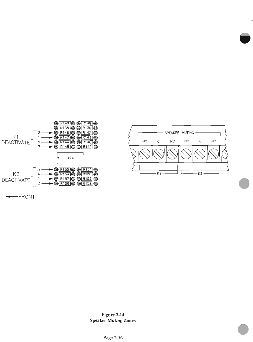
Figure
Speak
Page
2-14
Muting
2-16
Zones
Page 25
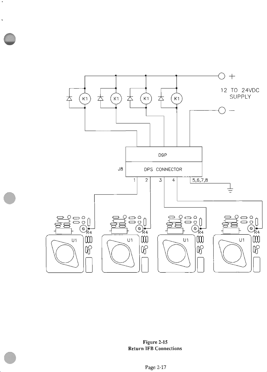
J8
I
DPS
CONNECTOR
I
TO
24VDC
SUPPLY
Return
Figore
IFB
Connestions
Page
2-15
2-17
Page 26

CH
A-B
2
r--1
-1
-
I
I
IFB CENTRAL ELECTRONICS PCB
4010
I
CH
A-B
4
=
ONE OUTPUT: INTERUPT; ONE OUTPUT: NON-INTERUPT
A
B
=
BOTH
OUTPUTS:
INTERUPT
(CONTROLLED
Figure
Stereo-Mono
Page
BY
2-16
IFB
2-18
INTERUPT
Selection
SWITCH
AND
LEVEL)
Page 27

SECTION
3.l
3:
INTRODUCTION
OPERATING MSl'RUCI'IONS
3A
USER STATION OPERATION, MODEL
4020
The Series
dkussion below covers
ad operation of
umueetion of
considerably
physical contiguration of the studio,
theatre,
basics
3.4
through
32
SETUP
ELECTRONICS, MODEL
Mer you
headset into the test jack on
model
input
program. Then check programs 2 and
the program level
4000
depending
golf
course,
fm Model
3.7
AND
have
4010.
1,
turn
the
IFB
the
the
Model
System
is
very
initial
setup
equipment.
4020
on
your
eacy
as
Fi
User
needs
to
well
Station
and on
truck,
etc. you have to equip.
4020
setup are discussed in sections
below.
OPERATION OF
4010
made
all
codoas, plug a stereo
Wfi
program playing into program
monitor switch to PGM 1 and
is
louder
than
THE
CENTRAL
the
front panel of the
3.
the
mic monitor and
use.
The
as
the
setup and
vary
the
arena,
The
ve*
Caution:
the output monitor levels. To set program level to the
User Stations, tum the monitor selector switch to
OUT
1.
Set program-select switches under
1
to the de&ed channels Set the program level to its
midpoint. Have someone depress an
a Control Station and
speak
into the microphone.
IFB
OUTPUT
1
button on
Compare the interrupt level with the program level
and adjust program levels
as
needed for a balance
between the program and interrupt audio. Repeat
this
procedure for the remaining outputs. When the
is
monitor-select switch
in the
headphone redeves the
intermpted. The right headphone redens
SA
position, the left
SA
program before it
SA
audio
after the interrupt switch
33
CONTROL STATION OPERATION
MODEIS 4001p001~2,4002M~,4003M
To
use
a Control Station, press the button or buttons
of the chameI(s) you
wish
to interrupt and speak into
the microphone.
Conaed
via
the User Station to
the
Spin
XLR-3
connectm
the
Central Ekdronics
on
the
rear of
Station. Polarity and correct codons are
important
the
andpin2hasthe
pin
the
operation,
for proper operation. To
connecticm~ to malre sure
+28voltsdconitwithrespedto
1.
In
tbeehre
nniatemrpted audio on
it
is
operations,
absolutely
it
essential
save
that
pin
pin
3
will
and no dc
that
pin
1
In
time,
is
have
2
dc(positive)andthatpinlbetheeommonorreturn
(negative).
stereo headphone jack on the
User Station. Adjust headphone levels
The volume controls
tumed
missing
When
mono headphone jack.
interrupted audio. Use
speaker into
User Stations may be paralleled
similar
pow
35
S-G
FOR
Any
for a
is
will
should
Plug a pair of stem headphones into the
rea~
of the Model
are
all
the
way
down,
made so
to prevrnt someone from
that
they
a cue.
using
a
single
earplug, plug
This
this
the
Model
4020.
splitter
up to three User Stations
IFB
RTS
4020
provide stem
have
box
The Central Electronics
W
INTERCOM STATIONS
USER STATIONS
TW"
intercom station may be substituted
User Station. The BP-501 User Stations
IFB.
Any other User Station
the channel-seleb switch set to
its
jack provides
jack when plugging a
with
our
per
output.
as
cannot be
cord into the
TW-4W
to receive the interrupted monaural audio.
User Station
used
to operate on a
distance
with
the
Local
Power
(LP)
dry
pair
IFB
feed providhg long
operation up to 8 kilometers
option
(5
miles)
stepup and stepdom transformers. See figure
the
User
check
common
dy
two-wire
carry
the
4020
desi~ed.
the
or
will
channel
A
TW"
can
be
with
31.
1
Page
3-1
Page 28

3.6
OPERATING
The
4020
Urn
telco
pair.
output to pins
connector going to
distances,
operated on
Balaneed/Unbalanced
where hum
Station
Just
two
WITH
attach
1
telco pairs
TELCO
can
common
and
2 r&ely on
the
is
a problem,
converters at each
DRY
be
operated on one
and
User
Station.
the
in
steru,
PAIRQ
the
interrupted
For
4U.20
with
one of our
end.
TI
"dry"
the
can
XL
long
be
3.7
OPERATING
With
a telco pair, maximum operating
average
conductors
operating range
extra
be
pair.
800
power
extended to 8 kilometers
See
figure
DISTANCES
meters (1/2
in
a telephone
to
1600
meters (1
supply and transformers,
3-1.
12VDC
TO
2mc
mile).
quad
(5
distanae
Doubling up the
will
extend
mile').
miles)
Utilizing
the
range
on telco
will
the
an
can
dry
1r
MODEL 4010
TI,
T2:
7
SENTINEL 42TU400
,,$$
5
MILES
LJ
TWlSlED
PAlR
OR
EQUIVALENT
/4w
1
MODEL 4020
TW
STATION
wmc
POWER OPTION
+
LOCAL
LOCAL POWER
Figure
Range
Page 3-2
3-1
mder
Page 29

SECTION
4.1
INTRODUCTION
l%e
severid
systems
power amps, relays, power supplies, and high-power audio
tmnsfonnem. The Series
microphones, pmps, Control Ststions and a small
Centrnl Electronics. The Cmtral Electmnics contains logic,
electronic audio switches, dc power drivers that
superimpose audio on
Older
users.
The Series 4000
on dc. Neither the lielevel iudioior the dc
into the other cablea Tbe dc supplies power at the
user
location. The advanced design of the Series
then offers the following advantages over older designs:
4:
THEORY OF OPERATION
Series
end to
4000
IFB
system
disadvantages of older conventional systems. Older
consist
of microphones, preamps, Control Stations,
the
systems
iften
drive high-wwer audio down the lines to the
crosst&~~-into adjacent microphone cables.
IFB
svstem suoerimwses lielevel audio
nm
a small power amplifier at the user's
No crosstalk
Reduced weight
Reduced
Reduced
Reduced air conditioning load
Reliable and quiet electronic switching
size
energy
requirements
is
designed to overcome
4000
system consists of
dc, and a built-in power supply.
crosstalks
4MX)
system
IFB
4.3
CENTRAL
ELECTRONICS FUNCTIONAL
DESCRIPTION
POWERSUPPLY
The
power supply consists of
diagram
PC
ractifiers consisting of diodes D73
provide filtering. C83
causing radio fresuency
three
volts,
polarity-revd pmtection to
any of the supply
limiting
U33 (schematic upper right) provides
power the op amps.
U32 (bottom center) provides 12 volts
amps
U30 (bottom right) pmvides 12 volts dc to power the
CMOS electronic switches
U31 (top lee) provides 12 volts
headphone amplifiers.
SD1914).
of each transformer
qmak
26
volts, and
each
supplies
+
rails
to
the 40-volt supply.
T9,
T10, and TI1
rated
at
10 volts
is
rectified by full-wave bridge
-
C94
prevent D73
interference.
are
co1111d
40
volts
the
be
shorted. U29 provides
nnd
the other digital IC's.
rms.
-
D84.
The
outputs
in
series to provide 13
dc.
D8S - D87
filter
capacitors
20.5
dc
to bias
dc
to paver
(schematic
The
10 volts
C65
-
C67
-
D84
from
of
these
provide
should
cunmt
volts dc to
the
op
the
monitor
4.2,
OVERALL FUNCTIONAL DESCRWITON
The series
components: Control Station,
Station. The Control Station co~ects to the Central
Electronics through a SO-wnductor ribbon cable. The User
Stations
microphone cables with XLR
and a
button SS in
control lie to the Central Electmnics
is
pulled low, pulling the tally line to other Control
Stations low. DI9 is
to go to
of switch S5 to the Central Electronics. The control signal
causes
switch from program to the audio from the Control Station.
Output from the switch
driver which adds the audio to 29 volts dc.
passes
At the User Station a regulator takes power from the
combined audio and dc line to operate the headphone
amplifiers. The headphone amplifies take the he level
audio from the Central Electronics and amplify it to drive
headphones.
4000
IFB
system consists of three major
Central
CM
connect to the Central Electronics by
comector~
terminal
the electronic switch in the Central Electronics to
through the microphone cable to the User Station.
strip
at
the Central Electronics. When
figure
4-1 is pressed at the Control Station a
also
pulled down, causing lamp DS2
full
brightness. Audio is fed through another pole
is
fed to a buffer amp and acldc
Electronics, and User
at the User Station
IFB
is
grounded. Dl16
This
signal
Dl08 with {of U21 (center right) pmvide
the program buses for the CMOS switches.
6
volts dc to bias
Page 30

COMROL STATION
MODELS
MIC-PRE
I
4001
CENTRAL
ELECTRONICS
-
Line
Diagram,
Fi
Series
4-1
4000
IFB
System
Page 31

PROGRAM AUDIO
INPUT
SPEAKER
MUTE
The pmgram enters at the rear terminal strip through
resistors R241
T2
-
T4.
unbahced audio for switching. The
is
then coupled to the pmgram buses through CEO - C82.
The buses
allow an audio signal of up to 12 volts
through
CONTROL Sl'ATION AUDIO
The
Control Station balanced line-level microphone audio
enters the unit through T5
fed to four "mic' buses. This will
'mic'
signal. For channel
passes
'Program' is the audio that enters through the rear-panel
ted strip and
passes
to the input of the summing amp { U2. From there the
audio
voltage
added to the 29 volts dc at the output of U1.
The nonintermpted audio passes through pmgram select
switch S3, front panel level control R16B, internal mono-
stereo
u2.
through S2 to R16A, the program level control.
through R13, the CMOS switch (U3), R10, and
is
switch S1, and the buffer amp, the
-
R246,
R158 - R160, a bridging
Thess
transformers convert
are
biased
at
6 volts dc with R229 - R231 to
the
CMOS switches without distortion.
the
balanced audio to
unbalanced
peak
to
pad,
peak
program
to
INPUT
-
T8 where it is unbalanced and
be
refered to
1,
interrupted side, program
transformers
unt~led through C3 to the adjust terminal of
reguhtor
U1. ~s causes the audio signal
T2
-
T4. From there it
second
as
to
half of
and
pass
the
C5
be
When
pressed, D67 (lower right)
the SA button on Control Station number
is
pulled low, pulling pins
and 3 of U24 low. This
turning
example, R147
activated from Control Station number
on
Q5 and
is
SrEREo MONITOR HEADPHONE
S14 (upper left) selects
headset.
gahof50andcm~pply anhputpbwerof 1 w&butpre
limited
4.4
The
7307
to
about
{
wntt
CONTROL STATION FUNCTIONAL
Q6,
and
cut
out,
oower
by the 10
which
causes
~m~lifiem
pin 13
energizbg K1
then
QS
and
1.
pgnm
&I25
ohm
rasistor.
and
1
and
K1
AMP
is
hcud
and
to
K2.
will
U26) have
go
in
1
high,
If,
for
not
the
ttst
11
be
DESCRIPTION
POWER SUPPLY
ac
is
14 volts
through TB2 (schematic SD2043)
wave bridge rectifier colLFistig of diodes D3
and C11 provide filtering. U2 pmM
sensing the voltage drop
set at 250 milliamps for the Model 4001, 570
the Model
Q2 provides a consbut current
diode D8 which gives 4.7 volts to
supplied
4002 and 1.3
from
a wall-mount transforma
and
is
rectified
current
across
R12. The cunent limit
axups
for
the
Model
at
high
isol.tion
Vies
the
op
by
-
D6.
limiting
ndhmps
4003.
to mer
amps.
a full-
C10
by
for
FET
is
a
is
When the
pressed, D51 is brought low.
causing switch C to switch from audio ground to the MIC
bus.
13 to go high and switch
14 of inverter U6
thus
D29.
ACIDC
R5
across
Ul is pulled low, keeping the output dc (through R5) equal
to or less than 200 milliamps.
TALKBACK
The setting of R4 determines the cumnt at which the
takback relay trips. When
and
pulling the
energize the coil of the external talkback relay.
IFB
1
switch in Control Station number one is
This
pulls pin 9 of U3 low
Pm 10 of nand gate US is also pulled low causing pin
B
to disconnect the program.
is
pulled low causing pin 15 to go high,
inhibitiug the lower priority stations through D27
LINE
DRIVER
is
the current-limit sense resistor.
R5
is greater
base
of Q1 is greater than 0.6 volt, Q1 conducts,
base
than
1.9 volts, the adjust terminal of
IFB
SENSE
the
voltage behwen the emitter
of 47 up. This causes 47 to conduct and
When the drop
Pi
MIC-PRE
The signal from the microphone enters
preamplifier through TB1, terminals 3 and 4, where it
amplified by U1. The
1
by R7 and R5. The
and
The limiter senses the output level of U1 through R10.
-
rolls off fraauencies above 700
affected by ;licks and pops. Trim pot
of the limiter.
circuit
with
is fed to the gate of Ql.
more negative the gate of Q1 is. This
and it's mistance
to reach the negative input of U1 thus reducing the gain of
the circuit.
The output of U1 is fed to one side of TI, C15 is normally
connected to the centertap. The balanced audio output
fed through P1 to the switch board.
&
LIMITER
is
approximately 54 dB.
C6,
Dl, and D2 form n voltage doubler
that
charges
the
output level of U1.
C3 with a negative voltage
to
minimum
maximum
go high. This allows
gain
(27 dB) of U1
gain
is
set by R7 and Q1
Hz
so that the
R9
sets
This
negative control voltage
Tbe
stronger
the
causes
the
microphone
limiter
the threshold
sigd
Q1 to
more
is
is
that
variea
is,
turn
feedback
is
set
C9
less
the
off
is
Page 4-3
--
--
Page 32

4001
SWITCH
BOARD
The audio
pressed, the switch
to
13,
AU
switches
a darkened room.
bright
Diodes
brightnsss
Dl20
control signal
J2
pin
Control Stations.
on.
When the
are
pulled low.
as if
on bright,
mds control signals to the Central Electronics for
IFB4. D25
dl
button
Dl16 - Dl20
triggering this station's control to the Central Electronics.
Dl8 - D23
lamp
is
received through
is
pins 7 and
8.
are
illuminated so that legends may he
The
when
the
button
D9.
D10,
and
sink
for the
md pin 1 of
1
low.
IFB
all
the buttons
sends
is
pressed.
level bus current.
J3
back
to the Central Electronics.
J2
pin
D23
W
button is pressed
D26 - D29
had
tally signals to other Control Stations, and
causes
the SA function to
prevent another station's tally signal from
prevent one station from sinking all
J1.
When
any button is
closed and the audio
illumination
is
depressed and dim otherwise.
Dl1
make a 7 volt rail that is the low
lamps.
are
pulled low.
1
is
pulls lamp
pull aU the
been prd. This
Dl2 - Dl7
the
is
When
tally
DS6
passes
of a two level type,
IFBl
J3
pin 1 sends
signal
to the other
low turning it fully
D24,
and
IFB
signal linea low
turns
work
when the
power the lights on
through
read
is
pressed,
the
Dl20
pulls
D26 - D29
the
lights
IFBl
IFB
the
low
dim.
4002
SWITCH
The
4002
put together.
IFB
ALL
Central Electronics
button
is
preventing a hum loop from being developed.
BOARD
switch
pressed.
board
lb
only difference is that there is only one
button on the
is
K1
is just like two
4002.
switched by
isolates
the
two Central Electronics,
4001
switch
The
audio to the first
K1
when the
IFB
boards
W
dc
The
panel
through
output of VR1
in
and intcMpted audio
]a
connector (schemetic SD1905)
Dl
which
provides
is
set
for
revem
13
volts by
enters
downthenvrentnsponseofVR1.
VRl
a high
impedance.
C12
and
C15
AMPLIFIER
The interrupted
panel level control R10.
u2.
This
powerof(watt(viaa10ohmsafetyresistor).
intempted input
control
amplifiers
rear
4.6
-
The rehun
additional load at
by switching a number
the
Electronics by
determines the current
When the voltage across
greater than
up. This
external
switch the microphone
from the mixing console to a
near the director.
R1
panel.
RETURN
User
talkback
signal
is
coupled by
This
IC
has
a
g.ia
of
is
ooupled by
and
amplifid
are
made available thmugh
IFB
IFB
ths
Station. This
RS,
0.6
volts,
causer
Q7
relay.
See
by
FUNCTIONAL DESCRIPIlON
function is activated by
User
73
lamp
extra
for
chd
at
Q1
ducts,
to
conduct
The
mnciated
llso
is
fed
50
and
C1
U1.
Station. This
snoss
load
which
the
the
emitter
and
extemp1
separate
section
on pin
cunrat
R6
Thiskeepstheinpotto
The
two
snd
pmkdion.
and
R7.
provide
C11
to
can
to
)'
filtering.
snd
fed
power
amplifier
alpply an output
front
panel
outputs
phone
jacks
of the
pawea
C8
to
'Iheaon-
from
on the
w
The
slows
front
Level
both
adding
is
accomplished
the
12
volt
supply
is
ssnsed
1.
pulling the
mergizt
with
amplifier
2.2.3.
The
talkbe&
and
relay
that
m
the
setting
relay
base
base
the
is
thea
User
and
Ceatral
of
trips.
of
Q1
of
coil
of
used
Station
Bpeslrer
IC
m
in
R4
is
Q7
the
to
4003
SWITCH
The
4003
boards
button. The audio to Central Electronics one and two is
switched by
K3 isolate the
loops from being developed.
4.5
put together except
USER
BOARD
switch
K2
and
three
board
is
similar to
that
there is only one
K3
whm
IFB
ALL
Central Electronics and prevent hum
STATION FUNCTIONAL
three
4001
is pressed.
switch
IFB
K2
and
all
DESCRIITION
The
4020 User
amplifim md a regulator that has a high input impedance.
The hinh inwt im~edance reduces audio line losses and, in
additi&, diow tde
channel listen only station on the
Station consists of two headphone
4020
User
Station to
"W
be
used
as a dual
intercom system.
Page
4-4
Page 33

SECTION
5:
MAINTENANCE
53.1
INPUT
POWER
SELECTTON
a
5.1 INTRODUCTION
The
Series
4000
IFB
system should
maintenance other than
perfomawe
54 SERVICE INFORMATION
The
RTS System
warranted for a
The
wauanty is located
53
GENERAL
check
Series
period
MAlh'TENANCE
an
4000
of
three
at
the front of the
require
occasional cleaning and
IFB
system's components
years from the purchase
no preventative
book
are
date.
WARNING
TEE
FOLLOWING INSTRUCTIONS
BY QUALIFIED
ELECTRIC SHOCK, DO NOT ACCESS THE
INTERNAL SWITCEES. JUMPERS OR FUSE
UNLESS
YOU
PERSONNEL
ARE
QUALIFIED
ARE
ONLY.
TO
DO
FOR USE
TO
AVOID
SO.
WARNING
DISCO-
AC
POWER
BEM)RE
SERVICING.
TheModel401Oisdcsigndtooperatcon5Oor60Hs
ac
f
10%
with
the
volts
moving
mvened
5-2B).
534 CLEANING
Clean
components with
detergolt and water.
dry,
any
the solvent
533 FUSE
The
on
the
the
jumpers,
to
220-240
the
front
panels
denatured
low
pmsure
good
quality elecrmnic cleaning s01venL Avoid getting
air.
in
the switches.
REPLACEMENT
Mode1
4010
Central
the
rear
panel
is
unit
is
a 1
amp
jumpers
between TI0
volts
and the
Clean
The
circuit
Elmnics
a
314
amp
do-blo.
as
in
figure 5-2A. By
and
T11, it may
ac
f
10% ope-don (figure
cases
of the Series
alcohol
the
interiors
board
slo-blo
or
a
mild solution of
of
can
be.
has
two
fuse.
Ihe
the
cleaned with
fuses.
units
The one
fuse
120
be.
4000
with
inside
To get inside
of the
The bottom cover comes off the
To get hide the
and
then
front pad. Turn
holding the hack panel. Now pull the back off, and
circuit
on the control stations, remove the contm1 sfation from the
panel
thembertaboftheswitcheoveraway
Pull
gently fornard on the switch cover.
switchasitwillbreak. Seefigure5-1.
the401OCen~Electronics,lift
top
cover and pull
the
knobs.
card
will
in
which
it
slide out also. Toremove the switch covers
back.
4020
Upa
Station,
Remove
the
is
installed. With a
the
unit
over and remove the four screws
The
theback edge
cover will
same
remove
nuts holding the pots
small
then
slide our
way.
thelmob covers
screwdriver,
fromtheswitchbody.
Do
not
force the
to
the
the
pry
Page 5-1
Page 34

LAMP
Figure
hp
Replacement
Page
5-2
5-1
Page 35

Input
Figure
Power
5-2A
Seleclion,
Page
5-3
120
VAC
Page 36

IF0
CENTRAL
PCB
4010
UECT
I
Input
Figure
Power
5-2B
Selection,
Page
5-4
240
VAC
Page 37

5.4 PERFORMANCE CHECK
4010
TEST
5d.1 MODEL
PROCEDURE
l?qdpment Needed:
Four Control Stations (40010,
4002(M),
or
40030):
A 4020 User Station.
Three
program soum (oscillators etc.)
Stereo headphones
OsdIIoscope
Voltmeter
Ac Voltmeter
Cable assembly
Variable voltage power transformer
I.
Power
Supply
A
With variable voltage transformer,
slowly, check for excessive current drain. Measure the
volt, 24-volt, and 40-volt supplies.
check for 14,27, and 40 volts
B. Check for 29 volts
C
Short each output whiie measuring the voltage
C
C
10%.
1
volt on each output.
the respective lo-ohm, 5-watt resistor. Measure
C
02
across
each resistor with output shorted.
n.
Program
Set
all
minimum.
bputs
channel select switches to
Feed
a 1-kHz tone to program channel
turn
voltage up
13-
With 120 vac input,
across
1.8
volts
1,
all
controls to
1,
100-Hz tone to chaqel2, and a 10-kHz tone to channel
3.
Set tone level for
+4
dBu.
With program input, listen with belt pack on channel
Listen for noise. Set controls for program in both
mono-stereo switch in stereo position.
IFBl,
listen for interrupt in the left
holding priority 4 down, press priority
override. Release priority 4.
While
priority 2 IFB1, listen for override. Release
holding
2,
press priority 1 IFB1, listen for override.
Releaseboth buttons. Move mono-stereo
Press priority 4
ear
only. While
3
IFB1, lien for
holding
3,
3.
switch
mono and check for interrupt in both ears.Repeat for the
other 3 channels.
IV.
Headphone amp.
Plug test cable with 50-ohm load on each channel into test
headphone
jack
Turn
monitor switch to Program
increase monitor level and check for clipping at 9 volts p-
p on left channel.
3.
Check for signal level greater than 4 volts pp. Repeat
Turn
monitor switch to program 2 and
for right channel.
Turn selector switch to SA, adjust SA controls so that
program is visible on
on priority 1-4 and
oscihmpe.
check
for interrupt. Note: there is no
Push the SA1 button
priority on SA.
Turn
selector switch to mic
1,
press any priority 1 button
and check for tone. Repeat formic 2-4 (priority 2-4).
Plug in headphones to test
dimortion on
all
positions.
jack
and listen for noise and
a
5.4.2 MODEL 4001 CONTROL STATION
PRETEST PROCEDURE
MIC
1.
ears,
press
While
to
1,
A
With
an
doscope
on INT output
1,
turn
up level,
watch for smooth operation of the pot, output level
should reach
then to
15
dB.
-4
3,
check to
dBu. Switch program to channel
see
that the level drops no more than
2,
Move the odosmpe to NON-INT output
and
check for maximum level and switch program to 1,2,3.
B.
Repeat Afor channels 2 through
C.
SA. Connect
scope
to SA out, load with 2kilohms,
4.
check for -1.2 dBu (1.8 voltsp-p). Check programs 2
Equipment Needed:
Oscillosmpe
Audio signal generator
1,
Test jig with adapter cable
Inspection
Inspect the unit for missing parts or damage.
&
3.
Page 38

Test
Test
Connect 14 volts
123 millivolts p-p at 700
Pin 4
is
ground.
capacitors
Connect a scope with a 4,700 ohm load to pins 1 and 2 of
PI.
Adjust
Reduce
output signal should
input frequency to 100
should remain
5A3
TEST
Equipment Needed:
Oscilloscope or stereo headphones
Two audio signal generators
Central Electronics, Model 4010
Tested Model
Splitter Assembly, Model 4025
input signal
MODEL
PROCEDURE
ac
to terminals 3 and 4 of TB27. Apply
Check
the limiter pot,
by
20
be
Hz,
above
4.0 volts p-p.
4001
IFB
4001
Hz
to terminals 3 and 4 of TBl.
for 17 volts dc on the Wter
R9,
for 6.0 volts p-p output.
dB
to 123 millivolts p-p. The
above
5.0 volts p-p. Change the
then to 10
CONTROL
kHz,
STATION
The signal
Observe that the lights come on dimly.
the oscilloscope (or listening in the headphones) press the
IFBl button on the unit
in signal from the pmgram to the
light
to
go bright on both Control Stations. Release IFBl
and press
the lights to go bright.
Turn
test for IFB2.
Turn the monitor select switch to OUT
IFB
ALL,
the monitor select
being
check
switch
tested
mbpre.
for the
change
to OUT 2 and
While
watching
Notice the
Look
in
signal
repeat
3
and
repeat
change
for the
and
all
the
£01
1FB3.
Turn the monitor select switch to OUT 4 and repeat for
1FB.I.
Turn the monitor select switch to
oscilloscope to ring of monitor headphone
repeat for
SAA
PROCEDURE
Equipment Needed:
SA.
MODEL
4002
IFB
CONTROL SFATION
SA.
Conned the
jack,
and
"0
Check
for damage or missing parts.
frayed
wires.
an LM317MP.
Setup
Connect the left channel of the monitor headset
from the 4010 to the oscilloscope, or plug in a
stereo headphones. Set the 4010 for program on
outputs and the SA output. Set the monitor select switch
to OUT
wnnector into 13 (the one nearest the board edge). Plug
the fXth 10-pin wnnector into J2. Plug the 50-pin
wnnector into the Splitter Assembly. Plug a tested 4001
into the Splitter Assembly also. Plug the splitter into the
4010 Central Electronics.
Qnnect a mic level signal (123
input on the mic-pre, terminals
power wrds of both 4001's into 120 volts
Check
that R12 is 5.1 ohms and that U2 is
1.
On the 4001 being tested, plug the first 10-pin
Check
for broken or
jack
all
mV
p-p) into the
3
and 4 of TB1. Plug the
ac.
mic
(tip)
set
four
level
Oscilloscope or stereo headphones
Two
audim
signal generators
Central Electmni~s, Model 4010
Tested Model 4002
Splitter Assembly, Model 4025
of
Check
for damage or missing parts.
frayed
wires.
an
LM317MP.
Setup
Connect the left channel of the monitor headset
from the Model 4010 to the
of stereo headphones.
four outputs and the SA output.
switch to OUT
10-pin wnnectors into 17 and I8 . Phg the
connectors into J5 and 16. Plug the
Check
that R12
Set
1.
On the 4002 being tested, plug the
is
22 ohms and that U2
osdbscope,
the 4010 for program on
Check
Set
for broken or
or plug in a set
the monitor select
Mh
50-pin
connector that
jack
lbpin
is
(tip)
all
first
Page 5-6
Page 39

comes from J5 and J7 into the Splitter Assembly. Plug a
tested 4002 into the Splitter Assembly
splitter into the 4010 Central Electronics.
Connect a mic level signal (123 mV p-p) into the mic level
input on the mic-pre, terminals 3 and 4 of TJ31. Plug the
power
wrds
ofthe
two
4002's into 120 volts
also.
ac.
Plug the
Inspeclion
Check for damage or missing parts. Check for broken
bayed
wires
LM317T.
Set
Up
Check that R12
is
1
ohm and that U2
is
01
an
Test
Observe that the lights come on
the doscope (or listening in the headphones) press the
IFBl button on the unit being tested. Notice the change
in signal from the program to the mic-pre. Look for the
light to
and press IFB
the lights to go bright except for the IFB
tested 4002.
Turn the monitor select switch to OUT 2 and repeat the
above
Turn the monitor select switch to OUT 3 and repeat for
IFB3. Test
Turn the monitor select switch to OUT 4 and repeat for
IEB4.
Turn the monitor select switch to SA.
odoscope to ring of monitor headphone
repeat for SAl.
Now unplug the 50-pin cables bom both units and attach
them
Repeat the test for IFBS
IFB
go
bright on both Control Stations. Release
ALL,
check for the change in signal and
test
for Irn.
to
the other 50-pin connectors on the 4002's.
-
ALL
lamp will light on the 4002.
dimly.
IFB8 and SA2, noting that the
While watching
ml
ALL
on the
Connect the
jack,
Connect the left channel of the monitor headset
from the Model 4010
of stereo headphones. Set the 4010 for program on
four outputs and the SA
switch to OUT
10-pin connectors into J12,J13, and J14 . Plug the fifth
lo-pin connectors into J9, J10, and J11. Plug the 50-pin
conneetor that comes from J9 and J12 into the Splitter
all
Assembly& plug a tested 4003 into the Splitter
Assembly. Plug the splitter
Electronics.
Connect a mic level
iput on the mic-pre, terminals 3 and 4 of TB1. Plug the
power cords ofthe
Observe that the lights
the oscilloscope (or listening in the headphones) press the
IFBl button on the
in signal from the program to the
and
light to go bright on both Control Stations. Release IFBl
and press IFB
the lights to go bright except for the
testei4003.
Turn the monitor select switch to OUT
above test for IFB2.
to
the
dm
output.
1.
On the
two
ALL,
-
4003
signal
(123 mV p-p) into the
4003's into 120 volts
wme on
unit
being tested. Notice the change
check for the change in signal and
-
Set
the monitor
being tested, plug the
into
the 4010 Central
dii.
mic-pre.
jack
or plug in a set
select
mic
ac.
While watching
Look
for the
IFF3
ALL on the
2
and repeat the
(tip)
all
first
kvel
all
5AS
MODEL 4003
PROCEDURE
Equipment Needed:
Oscillosa,pe or stereo headphones
Two audio signal generators
Central Electronics, Model 4010
Tested Model 4003
Splitter Assembly, Model 4025
IFB
CONTROL STATION
TEST
Turn the monitor select switch to OUT 3 and repeat for
IFB3.
Turn the monitor select switch to OUT 4 and repeat for
m4.
Turn the monitor select switch to SA.
oscilloscope to ring of monitor headphone
repeat for SA1.
Now unplug the 50-pin cables bom both
them to the second 50-pin connectors on the 4003's.
Connect the
jack,
units
and attach
and
Page 40

Repeat the above test for IFBS
the 50-pin cables from both units and attach them to the channel
third 50-pin connectors on the 4003's. Repeat the above
test for IFB9
lamp
will
5.46
MODEL
PROCEDURE
L
Set Up
A.
Equipment Needed:
-
IFBl2 and SA3, noting that the
light on the 4003.
4020
USER STATION TEST
Oscilloscope
Voltmeter
Audio signal generator
RTS Systems power supply or Model 4010 Central
Electronics
-
IFB8
and SA2. Unplug
IFB
ALL
(ring). Check the mono headphone jack for output from
Usten Test
Listen with headphones for noise and distortion.
5.5
TROUBLESHOOTING
This
section
system
If no sound is heard at the
Central Electronics
on the front panel of the Model 4010 to
29 volts dc on pins
the User Station. The audio level should
on pins
the User Station.
1.
is
designed to help locate which
is
at fault.
1
and 2. If there
belt
is
powered.
1
and 2 of the
is
dc and audio present, replace
pack,
Look
XLR
unit
check
to
see
that the
for the green
be
on. Check for
connector going to
be
1
LED
-
2voIts p-p
in a
If there
Check circuit board for damage or missing parts. Check
for proper insertion of ic's. Check for broken or
- -
wires.
C
Unit Set UP
Adjust both volume controls to minimum. Attach volume level on the Central Electronics
oscilloscope
(tip) of the stereo headphone jack. Stations, or remove the 50-pin plug at the Central
U.
Test 4010
Plug the unit in and check for 13 volts
capacitor C12.
Apply a 1-lrHz signal at 2 volts peak to peak to channel
This
may
with an RTS Systems
be
0.6
and to 100-Hz. The signal should remain above 0.4 volt
peak
Increase the INT volume control
just clipped, then
seen. The sine wave should
with 50-ohm load to the le£t channel output
f
1
be
done through the 4010 Central Electronics or
TW"
power supply. Output should
volt peak to peak. Change the frequency to 10-kHz
to
peak. Return the signal generator to
so
that the waveform
back
off the control until no dipping is
be
at least 9 volts pp.
frayed
mlt on filter
1
kHz.
shorted cable. Repair or replace the Central Eketronics
as
If there is dc but no audio, check to
enterine the Central Electronics, that the oroeram
selecteion the front panel sekadr switches Ad ;hat the
Check to
Electronics.
If a Control Station intempts but
see
should brighten when pressed. If the
still no audio, check the microphone connections
1.
terminal block on the CC4001
Station.
If a Control Station does not intermpt, check the cables
going to the Central Electronics. Make
priority plug on the Control Station
is
Replace the Control Station If
replace the Central Electronics.
is
necessary.
see
as
required.
that it
is
no
dc
and the green
if any buttons are pressed on the Control
I£
still no
powered. The buttons should
audim,
LED
is on, check tor a
see
that program
repair
or replace the Model
has
no audio, check to
be
unit
is
card
of the Control
is
turned up.
lit dimly and
powered but
sure
are
plugged in.
stin
no results, repair or
at
the
that the
is
is
Repeat the procedure for channel
channel 2 and checking the right headphone output
2,
applying the signal to
Page
5-8
Page 41

SECTION
6.1
6:
LISTS
INTRODUCTION
OF
REPLACEABLE PARTS
This section contains
shipping list
of a part is the manufacture.r and the manufacturer's pan number.
6.2
HOW TO OBTAIN
Pam may
6.3
SHIPPING
1
;
1
1
6.3.1
final
be
obtained directly
Telex Communications,
12000
Burnsville,
Telephone:
Fax:
(800) 3230498
Model
Power Supply,
Technical
Shipping
Plastic Bag
FINAL A%EMBLY, MODEL
parts
lists
acd
instructions for ordering replacement parts.
assembly,
Portland Avenue South.
MN
(877) 863-4169
LIST MODEL
4001
Cwbol Station
back
PARTS
from
Inc.
55337
U.S.A.
4001
Calrad
45-768
panel and/or fmnt panel and printed circuit
Telex Communications, Inc.:
Manual
Carton
-
9000-2359-00
4801
-
9010-U)031)0
The
parts lists are divided into four sections:
board.
Immediately
following the description
Spacer,
Spacer,
Spacer, Hex
Cable Mtg Cradle Panduit
Hex
Washer,
Screw,
Screw,
Lens Cap,
Legend Plate,
Cable Assy.
Connector,
Hex
3/16
Jack
Lock
4-40
4-40
4-40 x 314
D
x
4-40
Screw.
#4
x
112"
x
314"
Flat
Clear
Flat
IFB & VI Per Dwg
10
Pin
Smith
3/16
H
x
1
TM,
9/16"
Elec
Internal Tooth
Phil,
Allen Set
EAO
WH.
3M
3473-6010
EAO
94ML
RD
NoThd, Smith
Smith
94020
TMlS4
Hardware
Pan Hd, Ye1 Cad
99-921.7
99-908.9
RA-47-50-7
2438
9016
Page 42

63.1
End
Assembly,
Model 4001 - 9010-2003-00 (continued)
1
1
6.32
Corn 50 Pin Male 3M 3564-1002
Ribbon
Insert
Rinted
Res.
Res.
Res.
Res.
Rcs
Res.
Res.
Res.
Res.
Pot, Trim
Cap, .Olnf/lKv
Cap, 47pf/50v C.D. Radial,
Cap, Mono .Oluf/50v
Cap.
Cap, 22uf/50v Mono Cer Radial 10%
Cap,
Cap,
Cap,
Cap,
Cap, Tant, .47/50V Radial
Diode,
Diode, IN6263
Transistor,
I.C. LM78LOSACZ
I.C.
Header
Term
Cabble
Labels,
Cimtlt
CF
CF
CF
CP
CF
CF
CF
CF
CF
50
Cond
Spectra
Model 4001 Per
Assembly,
10K
ohm
lOOK ohm 1/4w 5%
1OM ohm 1/4w 5%
L1K
ohm 1/4w 5%
220
ohm 1/4w 5%
2%
ohm 1/4w 5%
22K
ohm 1/4w 5%
22
ohm 1/4w
9.lK ohm 1/4w 5%
Linear
C.D.
Model
1/4w 5%
5%
1OK Piher PTClOLVlOKA
Disc
Radial
Ill
4001, Mic
m
.1
Lcad
Spacing
Mono .luf/*
Elec
lMIuf/25v
Elee
lOnf/l6v Radial
Elee laOof/l6v Radial
Elec
47uf/16v Radial
MRJ(n
J305
Socket, 8
Molcx 22-14-2044
PCB,
CC4000
Block
4 Poa
Transformer, Audio Born
Coupling
Die,
Diode,
Diode, IN5333 Zener Voltage Regulator
Lamp, 18 Volt
Switch,
Header, 4 Pa. Berg
Piece
MR502
lN4004
EAO
.1
Spacing, 1"
Axial
Motorola
Si
SS*conhr
National
Pin
Bmdy DILSP-101)
Mic
Pre
Bd
FAB
Per
~mrt
EAO
99-910
Motorola
1
Amp,
JKL
8099SBP
99-456
Momentary Lighted
65606404
251040453
LMW
4M1V
843l352801050
3382
Prc
Board,
Lcn&
Dwg
2000
P/B
CC4000
-
W30-EJ994JO
Page
6-2
Page 43

63.2
6
2
1
633
Rinted
Switch
Header,
Header,
PCB,
Front
circuit
Lens
14
72
4001
SwBd
Wnel,
Model
Assembly, Model
Holder Gray,
Pin,
DL
Row
Str, Berg
Pm Berg
65611472
(EAO)
FAB Per
4001 - 9070-2006-00
4001,
EAO
Mic
99-9208
65611414
Dwg
4375
Pm
Board,
CC4000
-
9030-199900
RTS Part Number
QQ
8.5
633.1
1
1
6A
Shipping
1
1
1
1
1
6.4.l
Descriation
Extrusion,
Front
Gooseneck
Gooseneck Wmkeen
Model
Power Supply, Wad
Tecbdcal
Shipping Carton
Plastic Bag
Final
Front Panel
Panel,
Model
Mic,
20"
Ust,
Model
4002
4002
Control Station
Manual
Assembly, Model
W/O
Grooves,
4'
x
1
314"
4001M Goosend - 9070-2360-00
-
9000-236100
45-768
4002 - 9010-201160
pTS Part Number
9050-2314-00
RTS Part Number
Spacer, Hex
Spacer,
Spacer, Hex
CabIe
Hex, Jack Saew,
Washer,
Saew,
Serew,
4-40
3/16
D.
4-40
MTG Cradle Panduit
Loclr
#4
4-40
x
112"
440
x
314"
x
314
x
3/16
x
1 Tbd,
9/16"
Internak
Phil,
AUen
Smith
H.
RD
Smith
TMW
EIee
Hdware
Tooth
Pan Hd,
Set
9402L
No
Thd,
9402(1
Yel
Smith
9016
RA-47-50.7
Cad
Page
RTS Part Number
6-3
Page 44

6.4.1
Finnl
Assembly;
Model
4002 - 9010-U)ll&l
11
11
2
10
2
1
6.42
Lens
Cap,
Plat
Ch
Legend
Cable
Connector,
Cona
Ribbon
Iasert
Muted
Res.
Res.
Res.
Res.
Res.
Res.
Res.
Res.
Rea
Pot, Trim
Cap, .Oluf/lKv
Cap, 47pf/50v
Cap, Mono .Oluf/50v
Cap,
Cap, .22uf/50v
Plate,
Flat
Wh.
Assy,
IFB
8t
W
10
Pin
3M 3473-6010
50
Pin
Malc
3M 3564-1002
Cable
50
Cond
Labels,
Cireait
CF
CF
CF
CF
CF
CF
CF
CF
CF
Mono
Cap,
Elec
Cap,
Elec
Cap,
Elec
Cap,
Elec
Cap,
Tant
Diode,
Diode,
Transistor,
I.C.
LM78L05ACZ
Voltage Regulator, National
I.C.,
NE5532N
I.C. Sodret,
Header Molex
Term
Transformer, Audio
PCB,
Model
Assembly.
1OK
ohm
loOK
ohm
10M
ohm
LX
ohm
220
ohm
2.2K
ohm
22K
ohm
22
ohm
9.X
ohm
Linear
W.
CD. Radial,
.luf/50v
Mono
1m/25v
lOuf/l6v
100uf/16v
47uf/16v
.47/50V
MRSOZ
IN6263
Bloek 4 Pos
CC4000
Motorola
1305
Signetics
8
Pin
2114-2044
Mic
1/4w 5%
1/4w 5%
1/4w 5%
1/4w 5%
1/4w 5%
1/4w
1/4w 5%
1/4w 5%
1/4w
1OK
Radial
Siliconix
Bwdy
Eleehovert
Pre
EAO
99-921.7
EAO
Per
Dwg
Spectra
4001
Per
Model
5%
5%
Fir
Dim
adial
.l
Lcad Spacing
.1
Spacing,
Cer
Radial
Axial
Radial
Radial
Radial
DILSP-108
Bouras
Bd
FAB
99-W.9
2483
843l35U#)1050
I11
3382
4002,
Mic
Pre
FTClOLVlOKA
2LS
1"
Length
lO%
LhC317MP
251010153
LM903
Per
Dwg
2000
Born
Page 45

6.43
6.4.5
Printed
Front
Chit
Coupling Piece EAO 99-910
CF
Res.
Diode,
Diode,
Relay, Gordos
Lamp,
Switch, EAO
I.C.
Socket,
Header,
Switch
Header, 14 Pin, DL Row
Header,
Panel, Model
Assembly,
100 ohm
MR502
lN4004
18
Volt
4
Pos
Lens
I2
1/Zw
Motorola
1
Amp,
835Q
JKL.
99-456
14
Pin
Bnmdy
Berg
Holder Gray, EAO
Pin
Berg
4002
8099SBP
65646404
Model
5%
400V
MO
Ohm, UV,
Momentary
DIL14P-108
STR,
65611-472
-
9070-2014.00
4002,
Switch
Lighted
99-920.8
Berg 65611-414
Fom
P/B
Board
1C
-
9030-437600
pTS Part Number
RTS Part Number
12
6.4.5.l
1
6.5
Shipping
1
1
1
1
I
Extrusion,
Front
Gooseneck
Gooseneck
Model
Power Supply, Wad
Technical
shipping Carton
Plastic
Front Panel W/O Grooves,
Panel, Model 4002M
Mic,
20"
Wmdsereen
List.
Model
4003
4003
Control Station
Manual
Bag
Gooseneck
9000-2363.00
45-768
4'
x
1
314-
-
9070-2361-00
9050-231400
RTS Part Number
RTS Part Number
Page
6-5
Page 46

65.1
FLnal
Assembly,
Modd
40Q7
-
9010-M19-00
652
Spacer,
Spacer, 3/16
Soaffir.
&ble
Hex
Washer,
Screw,
Sam,
Leac
Legend
Cable
C!ame&m,
Cone
Ribbon
Insert
mted
Res.
Res.
Res.
Res.
Res
Res.
Res.
Res.
Res.
Pot,
Cap, .Oluf/lKv
Cap,
Cap, Mono .01uf/50v
Cap, Mono
Cap,
Cap,
Cap,
Cap,
Cap,
Diode,
Diode,
Transistor,
I.C.
Hex
4-40
D.
Hex
4-40
~TG
Cradle
Jack
Screw,
Lock
4-40
x
1/2"
4-40
x
3/4'
Cap,
Flat
Plate,
Assembly,
10
50
Pin
M&
Cable
Labels,
Chit
CF
CF
CF
CF
CF
CF
CF
CF
CF
Trim
47pf/50v C.D.
.Zuf/Uhr
El%
Elce
Elee
Elec
Assembly, Model
10K ohm 1/4w 5%
lOOK ohm 1/4w 5%
10M ohm 1/4w 5%
1.1K ohm 1/4w 5%
220
ohm 1/4w 5%
22K
22K
ohm 1/4w 5%
22
ohm 1/4w 5%
9.lK ohm 1/4w 5%
Linear
.luf/SOv
1000~€/25v
10ufll6v
100uf/16v
47uf/16v
MR502
lN6263 Signal
J305
LM78LOSACZ
x
3/4 Smith
x
3/16
x
1
Thd
panduit
9/16"
P4
Internal
Phil,
Allen
Clear
EAO
Flat
Wh.
IFB
&
Pin
3M 3473-6010
3M 3564-1002
50
Cond Spedra 8431352801050
Model
ohm 1/4w
10K
C.D.
Mono
4002
Puher
Disc
Radial,
.l
.I
Cer
9402L
H.
RD
No
Smith
940U)
TMlS4
Elec
Hdware
Tooth
Pan
Hd,
Yel
Set
9P921.7
EAO
99-908.9
VI
Per
Dwg
Per
Ill3382
4003,
5%
PTClOLVlOKA
Radial
2LS
Lead Spacing
Spacing,
1'
Radial
Thd,
-
RA-47-50-7
Cad
2438
Mic
Length
10%
Axial
Radial
Radial
Radial
Motorola
Siconix
National
Smith
Pre
9016
Board,
CC4000
-
!J030-1999-00
Page 47

6.52
pry
Printed
Circuit
MDti0n
Assembly, Model
4003,
Mk
Pre
Board,
CC4MW)
RTS
-
9QU)-199P00
Part
Nmnk~
1
1
1
1
2
1
6.53
Voltage Regulator, National
LC,
NE5532N
I.C.
Socket,
Header Molex
Term Block
Transformer, Audio
Printed
Clrcnit
Coupling
Diode,
Diode,
Relay,
Lamp,
Switch,
I.C.
Header,
Switch
Header,
Header,
MI232
lN4004
l50
18
EAO
Socket,
Lens
Sietics
8
Pin
Bdy
22-14-2044
4 Pos
Elcdrovett
Bonrns
Assembly, Model
Piece
EAO
Motorola
1
Amp,
Ohm
5V
Cd
Volt
TKL
8099SBP
99-456
14
Pin
Burndy
4 Pos.
Berg
Holder Gray,
14
Pin,
DL
Row
72
Pin
Berg
99-910
Momentary
6564644
65611-472
LM317MP
DILSP-108
251040453
LMwCn
400V
Monser
DIL14P-108
EAO
Str,
Berg
4003,
Switch
ME431-2305
Lighted
99-920.8
65611-414
Bond,
P/B
CCQ000
PTS
-
9030.437700
Part
Numbex
65A
pry
19
65.4.l
1
1
Front
Panel,
Model 4003
W~tion
Extrusion, Front Panel
Front
Paml,
Model 4003M
Gooseneck
Goosend Wmckereen
Mic,
20"
-
90701202240
W/O
Grooves,
Gooseneck
4'
x
1
314
-
9070-236400
RTS
Part
9050-231400
RTS
Part
Number
Number
Page 48

655
65.6
Shipping
Final
Ust,
Model
4010
Spade
Ln&
Washer,
Nnt, Hex
Serew,
Scrcw,
Cable Tie Panduit
Rubber Stick
Teehaifal
Nylon
Kep
10-32 x 112"
6-32 x 318"
Manual
Assembly,
Model 4010
Central
T & B
Ektronics
RAZZ17
I10
Smith
6-32
Trnss Hd, Phil Cad
Trnss Hd,
PLT2M
On
Button Gray,
Mode1 4010
-
9000-2365-
2674
Phil
3M
-
9010-2W&00
RTS Part Number
Black
S15012
1
4
65.7
Washer, Nylon Sbouldcr Smith
Washer.
Nut,
Nnt, Hex
Screw,
Saew,
Saew,
Saew,
L.E.D.
Transformer
Knob,
Knob,
Knob,
Insert
Back
Lue
CaGe
Hex Jack Screw,
Nut, Radio Hex
Saew,
Saew,
Power
Strain Releif Heyco
Fuse,
Flat
H&
4-40
6-32 x 318"
8-32 x 318"
8-32 x 318"
Green
Black
Sie Blk
Dual
Labels.
Panel
Solder
MTG
4-40
4-40
Cord
314
3318"
K~P
k32
318"
x
114"
pan Hd, Phil, Ye1 Cad
Biding
Pan
Hd,
Plat
Hd, Pa Blk
Oshino
Can
Ah
Blk
Model
Assembly,
#4
Cradle
x
1/T
x
318"
6'"
Amp Slo-Blo Littlefuse
OW124
Hudson
KMOB-118
114"
Alcn
114"
Ah,
4003
Model 4010
Smith
1414-4
Panduit
9/16"
Elec
4-40
Clear
Pbil, Pan Hd, Yel Cad
Pan
Hd,
Gray Belden
1137
2668
Hd.
Phil
Oxd
HU-S36568&MU
KiWB
KSIOOB
Per
Ill
3382
-
9020-213900
TMlS4
Hdware
Cad
Phil, Cad
17237
RA-47-50-7
313.750
Page 49

65.7
65.8
Back
Pand
Assembly,
Fuse
Car&r Sehurter Fek 031.1666
Fuse
Holder
Cable
Assembly, Model 4010
Connedor,
Com.
Ribbon
Back
Cover Plate, Per FAB
Cover Assembly, Mcdel4010
Fibe&
Cover,
Printed
l0
So
pin
Cable
Pallel, Model 4010 Per FAB ]9181/FD1980
.008Thk
Top/Bottom
Circuit
Model
Body
Schurter
10
3M 34756010
Female 3M 3565-1000
50
Cond
14x16
Model 4010 Per FAB
Assembly,
4010
-
9020-2139.00
PCC
031.1653
Spectra 8431352801050
Dwg
2332
Dwg
Model
4010, CC4010 - 9030-197400
1982
RTS
Part Number
2xmMWm
280UXM3-00
9020-2141-00
2007~
2ao&ooUM)
WllMXll-00
9080-198MX)
9100-233243
9020-2140-00
l303mmw
9100-1982-00
RTS
Part Numk
Washer, lock #4
Washer,
Nut,
Nut, Pem 6-32 Pem
Nut,
Screw,
Res.
Res.
Res.
Res.
Res.
Res.
Res.
Res.
Res.
Res.
Res.
Res.
Res.
Res.
Res.
Res.
Res.
Res.
Res.
Res.
Res.
Lock
Radio
Hex
6-32
4-40
CC
33K
CF
100
CF
100
CF
lK
CF
10K
CF
l00K
CF 10
CF
150
CF
1s
CF
200
CF
22K
CF
22K
CF
22K
CF
22
CF
240
CF
39K
CF
470
CF
4.7K
CF
47K
CF
4.7
CF
5lK
Internal
#6
'61
Hex
4-40
Radio
x 318" Pan
ohm
ohm
1/4w
ohm
11%
ohm
1/4w
ohm
1/4w
ohm
ohm
I/%
ohm
1/4w
ohm
ohm
1/4w
ohm
ohm
ohm
1/4w
ohm
1/4w
ohm
1/4w
ohm
1/4w
ohm
1/4w
ohm
ohm
1/4w
ohm
1/4w
ohm
114w
Tooth,
Clear
Eng
Pattern
Hd,
lw
5%
5%
5%
5%
1/4w
5%
5%
1/4w
5%
1/4w
lw
5%
5%
1/4w
5%
Tooth
Cad
KFZ-632
Phil,
5%
5%
5%
5%
5%
5%
5%
5%
5%
5%
5%
Zinc
plated
Cad
Page
6-9
Page 50

Printed
Cirmit
Rea
CF
Res.
MP
Res.
MP
Res.
MF 27.4K
Res.
MF
Res.
WW
Pot, 50K Audio
Pot, lOK Audio Dual
Pot, DL 50K Audio
Pot, Trim
Cap,
lOopf/50rr
Cap,
mluf/lOOv C.D. Radial
Cap,
.Oluf/lkv C.D.
Cap,
220pf/50v Cer
Cap,
47Opf/5& Cer
Cap,
Mono .luf/%
Cap,
Elec
Cap,
Eke
Cap,
Elec
Cap,
Cap,
Cap,
Cap,
Cap,
Diode,
Diode, lN914B
Diode, lN4004
Diode, lN5234B Voltage Regulator 6.2V
Tmuktor, MPSU45 Motorola
Traodstm, MPS4355 Motwola, PNP
Tmuklor, 2NW1 Motorola, NPN
I.C., MC14012BCP Motorola
1.C" MC14049UBCP Motorola
Voltage Regulator L.M317K, National
Voltage Reor
Voltage Regulator, National LM317MP
I.C. SGS TBA-820-M
1.C
MC3358P Motorola Sub= 160.%3458-0P
I.C.
Analog
Relay, Gordos
Switch, Slide, SPDT CBrK 1101M2-CQ
Switch,
Swit4 Rotary
I.C. Soeket,
Assembly,
820
ohm
1.2lK ohm 1/4w 1%
243
ohm 1/4w 1%
ohm
4.m ohm 1/4w 1%
10 ohm 5w 5%
"CP
500
ohm Piher PTlOLV
Cer
330011f/25v
10uf/50v Radial
100uf/16v Radial
Elee
47Wv radial
Myh .luf/400v Radial
MMK
1/100V 10% Sub= 1516RlOI2U
Taut lOuf/l6v Radial
.Ol/Slrv,
Cer,
MRS02
Motrola
Sii
1
Switch RCA CD4053BE
835C3
3
Poa. PC Mt
12
8
Pi
Model
4010, CC4010 - 9QU)-197440
11%
5%
1/4w 1%
AB
70U4N040SM3A
Bonrns
'CP"
Disc
Di
Di
Di
.1
kdal
1400V Murata DE7150FZ103PVAl
Amp,
WlV
C&K
Pos. RCL U20lXQOB12UPJAR16
Burndy
8W24D15DlS
AB
26M906
Radial
-
Min
radial
Radial
Radial
Spa- 1"
400V
National
500
ohm, 12V, Form 1C
7'211-SPY-ABE
DILSP-108
1"
Leads
Length
RTS Part N&
Page 51

6.53
Printed
Cidt
I.C.
Sodret, 14
1.C
Socket, 16
Term Strip
J&
P~OUO
Transformer
Transformer,
#l3
Shield Bead Fairrite
Assembly,
27
114.
EWC
Audio
Model 4010, CC4010 - 9000.197460
Pin
Burndy DIL14P-108
Pin
Burndy DIL16P-108
Po6
Mpum
SMK
S-G~U
LP-20.6oO-B8
Bourns
Fnse, 1 Amp Slo-Blo, Littlefose 3U001
Fuse
Clip P.C. Littlefuse 102071
IERC
Heatsink
Heatsink
Header, 14
Header,
6.59
Front Panel, Model 4010 - 9070-1977-00
19
2
29
2
Ext.
IFB
Ext.
Support Bracket, Model 4010 Per
72
Front
Front Panel Side Rail, Model 4010
Side 10' x 13/4" Die 3780 Mat'l
462-To3
Aham
363
Pin,
Dl Row Str, Berg 65611-414
Pin Berg 65611-472
l2'
x
1
3/4"
Die
A104227Nl~R26
LM9003
26?3aXO1
3854
AUoy
6063T5
mT6
FAB
Dwg
RTS Part Number
RTS Part Number
2326
6.6
1
1
1
1
Shipping
Model
T&d
Shipping
Plastic Bag
List,
Model 4020
IFB
Belt Pack Talent Electronics
-
9OML236840
Manual
Carton
RTS Part NumM
Page 6-11
Page 52

6.6.1
Fii
Assembly,
Modd
4020
-
90101927M)
6.62
Washer,
Washer,
Nut,
Screw,
Knob,
Cap,
Nut
Back
Washer,
W&,
Nut,
Nut,
Screw
Cone
Phono
Com~
Wue, 24
Wue, 24
Wire, 24
Wue, 24Awg,
Wire, 24
Wire, 24 Awg, Violet S Long
Case
Pop
Extruded
ExtModd4020Case6'xTx11/2",ATI#~1
Belt
Ld
375-32
Teflon
Hex
f&l8 x 1/2"
Gray Selm S150-250
Gray
Cover,
Panel
Hex
Hex
440
Carbon
Jack,
3
Assembly, Model
Rivet
Qip
Seastrom
375-32
W/Dot
Gray Sifam,
Assembly,
Lodr
#4
Lodr
375-32
Kep
440
375-32
x
3/8"
Mic
Mono Switchd
Pin
Female Hirose
Awg,
Blue Vinyl Stranded,
Awg,
Brown
Awg,
Black
Red
Awg,
Green
Dome
Case,
Model
Per FAB
Internal Tooth
561237-40
Flat
Hd, Self Forming
SZam
C152
N1M
Model
4020
Internal
lOOde
Head
Tooth
Internal
R
Hd,
Switehcratt
HA16PR-3S
Vinyl
Vi~~yl,
Stranded,
Viyl,
Stranded,
S
Long
4020
Whim
4020
Per
Dwg
1385
Stranded,
-
9020-192640
Tooth
C/R,
Br
MN114B
N-111
F
5"
S
S
SSD
4.2
FAL?
Dwg
Wh
Zinc
FD18l8
6.63
Printed
1 Res.
3
1
1 Res.
2
4
Res.
Res.
Res.
Res.
Circuit
CF
10K
CF
10
CF
11K
CF
1%
CF
1M
CF
22K
Assembly,
ohm
1/4w
ohm
1/2w
ohm
1/4w
ohm
1/4w
ohm
1/4w
ohm
1/4w
Model
5%
5%
5%
5%
5%
5%
4020
-
9a30-190400
Page
6-12
RTS
Part
Numbcr
Page 53

6.63
Printed
Circuit
Assembly,
Model
4020 - 9030-l!W-O1l
(continued)
Q&
Dwcriutio~
Rw.
CFF
2.7 ohm
Res.
CF
470
Pot,
SOKAudio
Cap,
220pf/50v
Cap,
470pf/50v
Cap,
Mono
.lnf/50v .1 Spacing, 1"
Cap,
Elec
lOuf/l6v
Cap,
Elec
laOUt/lOv
Cap,
Elef
1aOUt/16v
Cap,
Elec
1000ut/16v
Cap,
Tant
lnf/35v
Diode,
Voltage
1.C
-~-~ - -
LC. Wet,
Rubber
lN4004
Regulator, National
SGS
TBA-820-M
~
8
Stick
1/4w 5%
ohm
1/4w
"(2"
AB
Cer
Disc
Cer
Disc
Radial
Radial
Radial
Radial
1
Amp,
Pin Burndy
On
Button Gray,
5%
7OU4N040S503A
Radial
Radial
Length
Radial
400V
LM317MP
DILSP-1W
3M
S15012
PTS
Part Number
Page
6-0
Page 54

Page 55

SS2000
Microphone
APPENDIX
PreampURer
A
Board
Engineering
Updates
RTS System
4002/4M)Ui2
If
your
guidelines and modify the
Carefully follow
1.
Diimect
the SSm
2
Remove
3.
Cut
other and heat
careful not to
the
has
moditied
and 4M)3/4003M Control Stations.
control
station was shipped prior to
the
inshuction below to make the modifications:
the
control station from the system and carefully note the positions of the
circuit
board. Died the cables and remove the SS2000 from the control
resistor
all
traces
annode
Rl2.
shown
the
damage
of diode
the
microphone preamplifier circuit board
Jan
12,1987 and
SS2000
as
area
D3,
in
your control station to
shown.
in
any of the traces next to the ones you are
cut the L shaped piece
To
cut
the traces, make 2 parallel
between with a soldering iron. The trace
SEE NOTE
away
exhibits
correct
from the
8.
A
(SS2000)
excessive
the problem.
pad,
noise and hum, follow the fadory
cuts
a 16th of
will
cutting.
not the long part of
used
When
in
the Models W1/400lu,
cables
connected
statim.
an
inch
apart
com
right off. Be extremely
cutting
the
the
leg.
trace
from
next
See
detail.
to
each
to
TRACE CUTS
LOOKING FROM CIRCUIT SIDE OF PCB
Page
A-1
SEE NOTE
8.
Page 56

4.
5.
6.
7.
Scrape
Install
to
be.
Add
3
Add
a
away
a
#22
#24
bus
wk
tk
AWG
AWG
SS2000
solder
wire
jumper
betwetn
Microphone
mask
on
with
a
wires
U1
pins
the
tenon
to
the
4
&
PmmpUfia
trace
of
sleeve
circuit
5.
APPENDIX
Board
Rl2
to
make solder
on
the
component
side
of
the board.
A
Engineering
pads
side
for
of
Updates
a
new
the
board
resistor.
where
resistor
W
used
SEE NOTE
r
w~~~
NOTE
5.
6.
JUMPER WIRE ADDITIONS
LOOKING FROM ClRCUiT SIDE OF
PCB
Page 57

8.
Add
R14
R15
Rl6
SSUlOO
the
following resistors to
(mbhm)
(1.X)
(9.X)
APPENDIX
Microphone Preamplifier
the
circuit
side
of the
board:
A
Board
Engineering Updates
/I-
LOOKING FROM CIRCUIT SIDE OF PCB
SEE
RESISTOR ADDITIONS
,-SEE NOTE
9.
Securely fasten the modified
9.
10. R-ed
11.
Corned the control staion to the system.
the
power
SSuXX)
supply and microphone
back
onto the control station.
cables
to their correct positions.
Page
A-3
Page 58

Notes:
SS2000
Microphone
APPENDIX
Preamplifier
A
Board
Engineering Updates
Page
A-4
Page 59

APPENDIX
ADD MOMENTARY
PUSHBUlTON SWITCH
i
-
-b
-
+I2
-
B
ADD
#73
12-14V
LAMP
AT
80rnA
OR
LAMP
Return
IFB
Model
F@m
Page
El
4020
ModiEcations
B-1
MODEL 4020
Page 60

Notes:
Page 61

NOTES
The following
with the Series
Model
#
HD-404
HD-4004-6
HD-44-6
list
consists of manufacturers names and earphones,
4000
IFB
System's Model
4020
User Station
Deschtion
Earphone,
Earphone, Stethscope
Earphone,
Earphone,
Earphone,
Headset,
Headset,
Headset,
Headset,
Headphone,
Headphone, Stethoscope style, Mono
Ear&,
Earset,
Earset,
Earset,
Sportcaster Headset
17
ohms,
70
ohms,
style
Mono
Stethoscope style Stereo
50
ohms,
600
ohms
lSohms,
50
ohms
50
ohms
200
200
MO
ohms w/left
500
ohms w/
MO
ohms w/left
500
ohms w/right
200
ohms
dual
Headphones, noise cancel mic
single
Headphone, noise cancel
ohms
dual
Headphones, noise cancel mic
ohms
dual
Headphones, noise cancel mic
200
ohm single Headphone
ear
right
ear mold;
ear
ear
6000
ohms dual headphone; omni
200
ohms
17
ohms,
17
ohms,
100
mold;
6'
cable
6'
cable w/wl cont
mold; S cable
mold;
5'
cable
70
70
ohms
w/vol
earsets
ohms
ohms
ant.
mic
and
headsets recommended for
mk
use
K-2MM
K-158
Headphone,
Headset,
Headset,
Headset,
200
600
600
zoo0
ohms
ohms dual Headphones; noise cancel
ohms
single
headphone;
ohms dual headphones;
200
Page
uX)
ohm mic
N-1
ohm
mic
mk
Page 62

&a!!&
MHS-11
Mini
Mini
Headset,
Headset,
2000
ohm
single earphone;
600
ohms single earphone;
omni
mic
omni
microphone
49@-150-001-694
491-150-001-694
Commentators Headsct,
Commentators Headset,
Earphone,
Earphone 8 ohms stehpe
l5
ohms
300
300
ohm single headphone; noise
ohm dual headphones; noise
style
cancel
mic
cancel
mic
Page
N-2
Page 63

SECTION
7:
DIAGRAMS
Assembly Diagram. P.C.B. Mic
Assembly Diagram. P.C.B..
IFB
Wiring Diagram.
Wig Diagram.
Installation
Wallation Dions. Models
Installation Dim. Models 4003. 4003M.
Installation Dimensions. Model 4010.
Jnstallation Dimensions. Model 4020.
Schematic Diagram. User Station. IFB System. Model
Lin~
Line Drawing. Comwting Block. Model 4WA
Dimmfions. Models 4001. 4001M
Drawing. Co~ecting Block. Model
System. Series
IFB
System. Series
Pre.
Control Panel.
Mic
Pre. Modifications To Update Rev
4000.
sheet
1
of 2
4000.
sheet 2 of 2
.
IFB Control Panel
4002. 4002M.
IFB
IFB
IFB
Central
IFB
User Station. Outline
4022
Electronics
...............................................................
.............................................................
IFB
System, Mod
.....................................................
.....................................................
Control Panel
Control Pauel 7-9
.............................................
.........................................
...............................................
4020
4000
.........................
C
Artwork.
Model 4000
.......
...................................
........................................
........................................
7-3
74
7-5
7-6
7-7
7-8
7-0
7-11
7-12
7-13
7-14
SD2043
SD2043
SS1973
AS4377
SD1914 B
B
B
B
B
Schematic Diagram.
Schematic Diagrsm.
Silkmeen Master. P.C.B..
Assembly Diagram. Control Panel. 12 Station.
Schematic Diagram,
EB
System. Control Station. Model 4001-4003. Sheet 1 of 2
IFB
System. Control Station. Model 4001-4003. Sheet 2 of 2
IFB
IFB
Central
(This
section
Central
Electronics. Model 4010
Electronics. Model 4010
revised
IFB
System. Mode1 4003
.................................................
March
1991)
.
....................
....................
.........................................
...............................
7-15
7-16
7-17
7-18
7-19
Page 64

Notes:
Page
7-2
Page 65

Assembly
Diagram,
P.C.B.
Mie
AS1999,
Pre,
Control
Page
7-3
Panel,
IFB
System,
Model
4000
Page 66

Assembly
Diagram,
P.C.B.,
Mic
ASS123,
Pre,
Modifications
To
Update
Rev
BUS
WIRE
6
TEFLON
C
Artwork,
Model
4000
7.
ADD BUS WIRE JUMPER BETWEEN Ul PINS
b.
ADD TO CIRCUIT SIDE: RI4 (220n)
NOTE: SCRAPE AWAY SOLDER
5,
ADD BUS
4,
ADO
I
3.
CUT
?.REMOVE R12. PUT A 4Z2 AW6 BUS WIRE WITH A TEFLON
PLACE
I.
FOR PART NUMBERS AND DESCRIPTIONS
NOTEJ
WIRE
JUMPER BETWEEN UI
r24
AW6 GRAY JUMPER TO CIRCUIT $ID€
TRACE
(5
PLACES).
(COMPONENT ZIDE).
:
MASK
oh
..
-
--
PINS
SEE
4
/
5.
6
b
7.
(3
PLACES).
PL 9030-1999-00.
PADS FOR Rl5.
SLEEVE
IN
tfi
.
nr-
DCV~
m
,,,,
-
I
".
--
DO*OTICUIIII*IO
uu
.."""-,
.W
-'-R
U
NEILSM
,.,,".
10a-&
Ym
ASSY-~?C.B.
MODIFIWITMNS
-
IP
B1
rur
-110
60572
2:)
MIC-PRE
1
TO
UPDATE
DIOm
1
,
AS
--
IF6
REV
5/23
-
.nn
4000,
C
MmwC
A
1".
Page 67

Page
7-5
Page 68

VVVVVVVVVV VVVVVVVVVV VVVVVVVVVV VVVVVVVVVV
JJIIIIIIII 1111111111 1111,0111 1111111111
111,111110 1111111110 1111111110 1111111110
-Nm-nmCOht 4NOILOUCII- ANmtnYCOId ?NOCWUCPI+
.......................................
~nmmmmmnmn
DDPDDCLP&L LD&&DLDDLD
0
111110111, 111111111,
0
1111111111 111111111, 1111111111 1111111111
1
111111111,
4
1111111111 II1IIIIIII
r
1111111111 1111111111
-
1111111111
N
dUNC0011nO 4WNCnO-mnO
I
In-m4m4n~I- N-NCNINl-n 4-4-4C-WN- N-NlNCNINn
........................................
0
N
CCCCCCCCCC CCCCCPCCCC CCCCCCCCCC CCCCCCCCCC
2
2222222222 2222222222 2222222222 2222222222
AAAAAAAAAA AAAAAAAAAA AAAAhAAAAA AAAAAAAAAA
nnnnnnnnnn
1,11111111 1,11111111 1111111111
1111111111
*rrtrrrr-1
DLLCDDCLPD
111111111, 111111111,
1111111111
111011111, 1111111111
1111111111 1111110111
UdCNInm-OD dmNCm01m10
nnnnnnnnnn
LDPLPLDLLL
IIIIIIIIII
~*lltlllllllkllllllIIII~II~IItIIIIkIIIIlll~ll
,,1,,,,,1,41111111111u11
~2-,m-ngggggd-mmln~rrrz~r(~
1,1111
rnrgorz--~mrnmszzz
141
111 111111
~~%&~~%uu~uu~l%~%%~8888~%~~&%8~988~%~~%~%8888
Page
7-6
Page 69

GOOSENECK
MODEL
MTG
4
PLACES
4001
SCREW
MIC
M
ONLY
7
H
2.0
+
5.9
TOP
33
(149'36)
VIEW
(03.53)A
WEIGUTS:
POWEE
4001
400lM
PACK
(KE)
I
L
2.7LRS.
1.4
LBS.
LC
(0.453kg)
(I.ZZ5kg)
(0.635Iq)
7.938
--
6.5
my..
(7.01.6)
(215.4)
AuuCAnal
-1
~
-
-a
ID2466,
Installation Dimensions, Models
CUTOUT
u--
-1m-
IOUYC..I;
lYODl-
s.
m*
-
1111
wmUURI*I(
4001,40OlM,
ALL
IFB
Control
Foe
CONSOLE
DIMENSIONS: INCHES
-.o_
PeODUCT
uu
mPMEu
-
U
LINE
'-l4%
,
um
.-
B
UU-
Panel
(mm)
MODELS
IFB
IN5TALLATIDN
mm.
60572
CONTKOL
A00
I, 4OOlM
DIMENSIONS
m.
*a
PANEL
ZAbb
Ism
I
or-
I
Page 70

ID2464,
Installation Dimensions, Models 4002,4002M,
IFB
Control Panel
-
I
"."
I
mwmom
-
m."
-
GOOS€N€Cg
MObEL
MT6
A
PLACES
WEIGUTS
mUEe
400ZM
SCREW
4002
400ZM
mCK
@EF\
MIC
ONLY
2.3LBS
29L85
1
4
LBS.
(10434)
(1.32kg)
(Qb35kg)
TOP
--
lOn-
VIEW
UumAm*
.
-0.
10.1.-
-I
/
m*OIUUIIUI.p
-
ALL
-D
PFODUCT
UOLY.
U-
=AMP'ELL
-
CCUSOLE
DIMEM510NS
LINE
~n
'-
:
IkKJCLIES
0
B
IWU-
(
mm)
MODELS
IF5
INSTALLATION DIMENSIONS.
mum
1
bOS72
4002,400ZM
CONTKO
DRD
1
L
PANEL
24d4
l
llnr
OF1
Page 71

GOOSENECK
MODEL
MTG
4
4000
SEW
PLACES
-+I----
1.250
(31.15)
MIC
M
-',
TYP
TOP
VIEW
r
I
I
-------7
-
1111
14
11
1-1
-
-
-
f
-
-
-
II
,I
II
,I
,I
1
-
-
-
-
.-
- -
-
-
-
-
-
-
-
-
-
+t+
I
I
-
-
I
1.720
(43.7)
(jS.6)
1
.I07
(4.7)
WEIGHTS:
WWEe
a
4003
4003M
PACK
REF)
7.4
LBS.
3.0LBS.
1.4
US.
(1.089
(1.3&1%)
(Ab354)
kg)
Installation Dimensions,
1'7.00
.
-A""
me.-
(40~.6)
.
--
1~2467,
Models
-1
U-R
m.m.131
-I;
-.
-
-
-.
--
4003,4003M,
Jn.
II
mmwouma
. - .
IFB
o..wT=
@DUCT
-w7
-
-
Control
YDIU.
Panel
LINE
-
ALL
DIMENSIONS: INCHES
MODELS
IF6
INSTALLATION DIMEN510N5
mn
?scam.
B
1
60572.
.w-I
4003.4003M
CONTROL
ae
m.
1
PANEL
2467
1-
(mm)
I
m.
IFF1
Page 72

Page 73

Page
7-1
1
Page 74

Page
7-12
Page 75

Page 76

I
Page
7-14
Page 77

Page 78

Page 79

Page 80

Page 81

 Loading...