

Page 1

Mini 200mW
User’s Manual
Page 2
Mini 200mW
User’s Manual
Copyright
Copyright of this manual belongs to R-TRON, Inc.
Reproduction, distribution or revision of part or all of contents in this manual in any form without written
permission of R-TRON, Inc. is prohibited.
Registered Trademark
R-TRON are registered trademarks of R-TRON, Inc.
Other products and company names mentioned herein this manual might be trade marks
or trade names of their respective owners.
RF Repeater
Band Selective Type
Sprint PCS
The results of using the information not mentioned in this manual or the risk of
misunderstanding this document remain with the user.
The information in this manual is subject to change due to function enhancement, change
of design, etc. If you want the modified manual or have any question on this manual,
please contact us with information below:
Address : Customer Support Center, Jisan IT Venture Bldg., 2/3F, 1004-9/10, Doksan-
Tel : +82-2-896-4101
Dong, Gumcheon-Gu, Seoul 153-829 , South Korea
Copyright © 2005 R-TRON, Inc. All Rights Reserved
R-Tron., Inc. 2/15 page
Page 3

Revision History
Version Date of revision Reason for revision
Ver 0.1 August 11, 2005
Revision Description
RF EXPOSURE INFORMATION
The antenna used for this transmitter must not exceed 12dBi and must be installed to
provide a minimum separation dist ance of 20cm from all persons.
Page 4

Mini 200mW
User’s Manual
Contents
1. Overview -----------------------------------------------------------------------6
2. Repeater Design ----------------------------------------------------------7
2.1 System specifications --------------------------------------------------7
1. Mechanical and Environmental conditions --------------------------7
2. System Electrical Specifications ---------------------------------------8
A. Mini 200 Repeater ---------------------------------------------------------8
B. Mini 200 Antenna ----------------------------------------------------------9
3. Repeater Configurations -----------------------------------------10
3.1 Body
1. RF Unit ---------------------------------------------------------------------11
2. Main Control Unit (MCU) ----------------------------------------------12
3. DC Power Supply Unit (PSU) ----------------------------------------12
3.2 Antenna Unit -------------------------------------------------------------13
1. Donor Antenna (Yagi Antenna) --------------------------------------13
2. Distribution Antenna ----------------------------------------------------14
-------------------------------------------------------------------------10
4. Block Diagram -----------------------------------------------------------15
4.1 Downlink signal path ------------------------------------------------15
4.2 Uplink signal path
R-Tron., Inc. 4/15 page
-----------------------------------------------------15
Page 5
Mini 200mW
User’s Manual
1. Overview
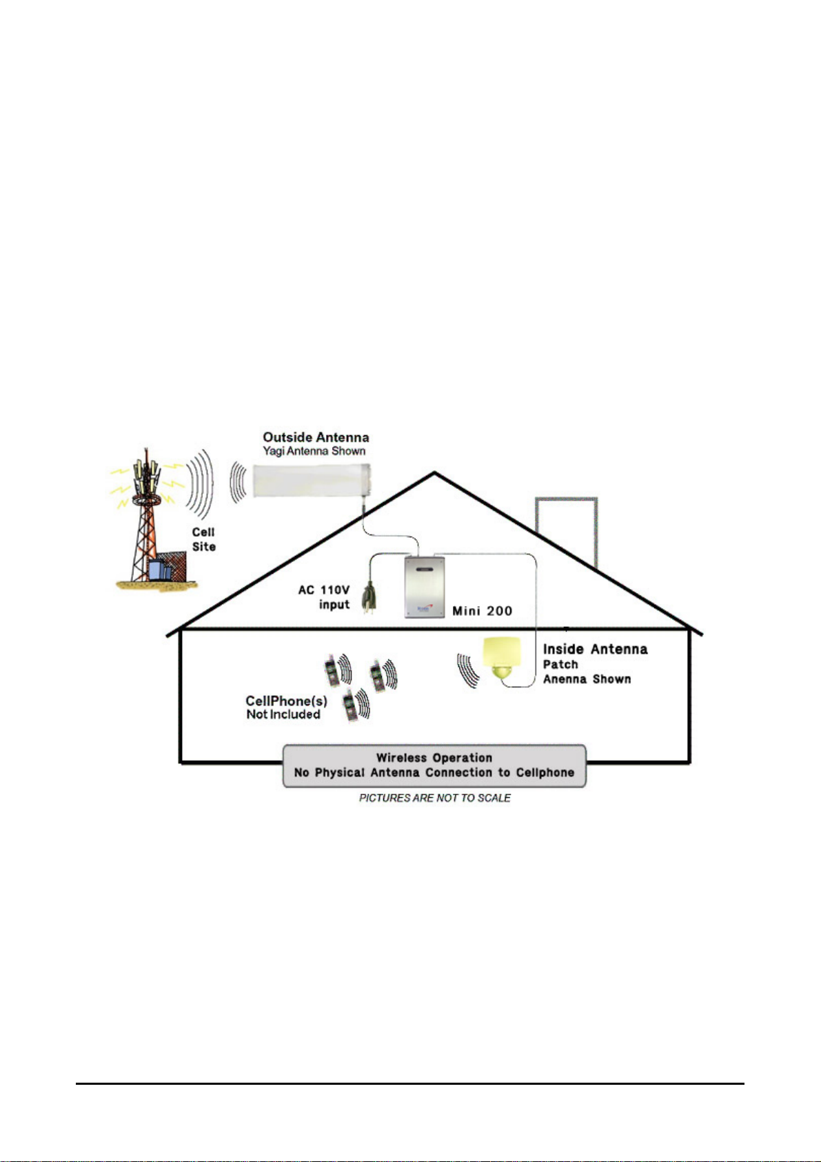
Mini 200 will bring in those weak cellular phone signals reducing dropped calls and allowing you to use
cell phones ...even deep inside a building.
At the heart of all of our systems is a Mini 200 designed to improve coverage for wireless products
within a facility. Combined with interior ceiling mounted low profile antennas, and an exterior mounted
Yagi or Patch Antenna, the Mini 200 boosts the signal level for distribution within the interior areas,
reducing the problem of dropped calls and signal fades. The Mini 200 can also be used in mobile
applications, improving voice quality and range in areas of poor coverage.
Figure 2.1 Fundamental configuration of Mini 200
All of our packages are engineered using only FCC approved amplified components. They are
designed not to disrupt local wireless communication but to add service to areas that otherwise would
not have the coverage that the customer requires. All of Mini 200 is easily installed.
R-Tron., Inc. 5/15 page
Page 6

Mini 200mW
User’s Manual
2. Repeater Design
The Mini 200 is housed in an aluminum chassis that is waterproof for indoor use. The chassis has a
design suited for indoor use.
The Mini 200 has several RF amplifiers and components on a board with an aluminum body.
Furthermore, the RF components are implemented within RF CMOS IC or MMIC technologies. A
board that contains several RF amplifiers and components is shielded under a metal cover. This
amplifier board is different types depending on the supported system.
The followings are the Technical Specification of Mini 200,
2.1 System specification
2.1.1 Mechanical and Environmental conditions
Parameter Specification
Power supply AC 120V +30/20%(AC 96~156V), 50/60Hz ±5%
Operating temperature 0 ~ +45℃
Humidity 10% ~ 85%
Consumption power 159W
RF connector N-female
Size(W X L X H) 280 X 430 X 115 (mm) / 11.02 X 16.93 X 4.53 (inch)
Weight Less than 33 lbs
Table 2-1. Mechanical & Environmental Conditions
R-Tron., Inc. 6/15 page
Page 7

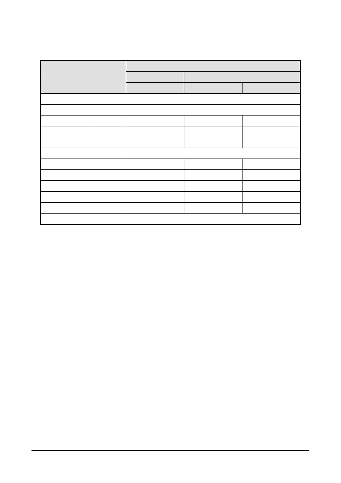
2.1.2 Electrical Specification
A. Mini 200 Repeater
Parameter Specification Remark
Mini 200mW
User’s Manual
Frequency Band
Transmit
Maximum Power
Gain Range 70 ~ 80dB
Gain Step 10 dB (1 dB Step)
Noise Figure < 5 dB
Bandwidth(Type 1) 5 MHz BW(Max. 3FA)
Bandwidth(Type 2) 10 MHz BW(Max. 7FA)
Bandwidth(Type 3) 15 MHz BW(Max. 7FA)
Down Link 1930 – 1970 MHz Total 40 MHz
Up Link 1850 – 1880 MHz Total 40 MHz
Down Link
Up Link
Gain
+ 23 dBm (200mW) Total Power on CDMA
80 dB ± 1dB
Any 5MHz of Total 60MHz
(A1,A2,A3,D,B1,B2,B3,E,F,C1,C2,C3)
Any 10MHz of Total 60MHz
(A1A2,A2A3,A3D,DB1,B1B2,B2B3,
B3E,EF,FC1,C1C2,C2C3)
Any 15MHz of Total 60MHz
(A,A2A3D,A3DB1,DB1B2,B,B2B3E,
B3EF,EFC1,FC1C2,C)
Any 20MHz of Total 60MHz
Bandwidth(Type 4) 20 MHz BW(Max. 7FA)
Passband Ripple < 2.5 dB P-P Operating Bandwidth
Delay < 12 microseconds
VSWR ≤1.5
Fc±885kHz ≥ -45 dBc
In-band Nosie
Fc±1.98MHz ≥ -50 dBc
Spurious Emissions < -13 dBm (Fc ± 2.25 MHz) RBW = 1 MHz
Table 2-2. Repeater Features
(AD,A2A3DB1,A3DB1B2,DB,BE,B2
B3EF,B3EFC1,EFC1C2,FC1C2C3)
RBW = 30 kHz
RBW = 30 kHz
R-Tron., Inc. 7/15 page
Page 8
B. Mini 200 Antenna
Ω
Mini 200mW
User’s Manual
Specification
Parameter
Frequency range 1850 ~ 1990MHz
Frequency bandwidth 140MHz
Antenna gain Min. 12dBi 2dBi 2dBi
Horizontal Min. 28° 70° 360°
Beam width
Vertical Min. 28° 70° 70°
Polarization Vertical
VSWR Max. 1: 1.5 Max. 1 : 1.3 Max. 1 : 1.5
Power Capability 50Watts 10Watts 10Watts
Antenna Connector Port Type N-Female N-Female N-Female
Weight (g / lbs) 670 / 1.48 225 / 0.5 270 / 0.6
Dimension (W x H x D) (inch) 19.69 x 4.21 x 3.23 5.04 x 4.06 x 1.54 Φ 4.49 x 1.85
Impedance
Donor Distribution
Yagi
Patch Omni(Optical)
50
Table 2-3 Antenna Features
R-Tron., Inc. 8/15 page
Page 9

Mini 200mW
User’s Manual
3. Repeater Configurations
The Mini 200 consists largely of a body and an antenna. The body of the Mini 200 has an RF unit, a
main control unit and a power supply unit. Specifically, the antenna unit is separated as a donor
antenna and distribution antenna.
3.1 Body
The following is the picture of the body of Mini 200.
Figure 3.1 A body of the Mini 200
R-Tron., Inc. 9/15 page
Page 10

Mini 200mW
User’s Manual
3.1.1 RF Unit
The RF Unit significantly functions an RF amplifier to amplify the weaken transmitted signal from a
base station.
Figure 3.2 An RF Unit of the Mini 200.
R-Tron., Inc. 10/15 page
Page 11
Mini 200mW
User’s Manual
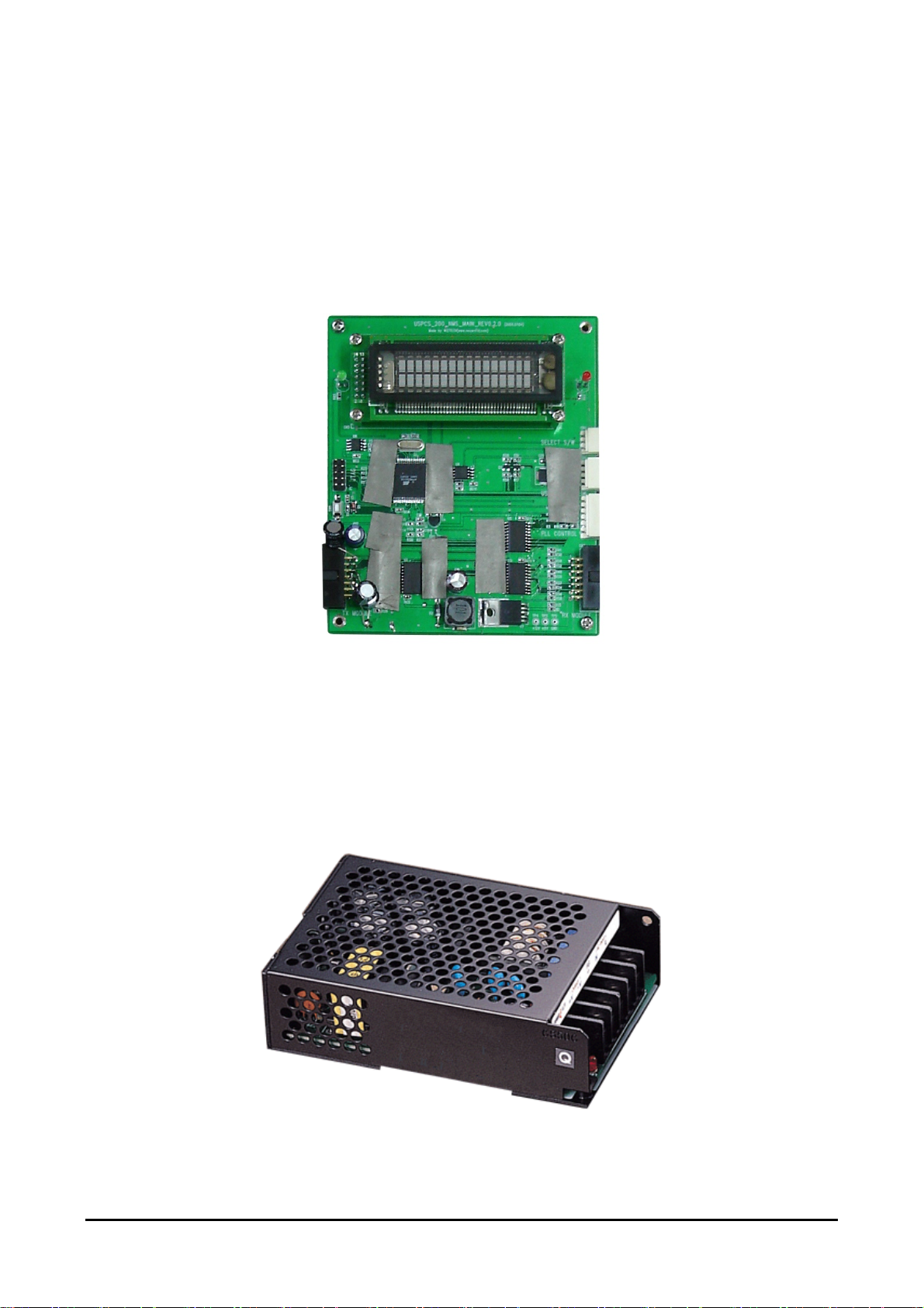
3.1.2 Main Control Unit (MCU)
The ARCU board is the control unit of the repeater. The ARCU board is used to supervise and control
operational parameters such as gain control, ALC handling, etc. The ARCU takes care of alarms and
the event log, password and logon, and many other procedures.
Figure 3.3 A Main control unit of the Mini 200.
3.1.3 Power Supply Unit (PSU)
The Power Supply Unit (PSU) roles in each needed dc power source as well as converter of ac power
to dc power.
Figure 3.4 Power supply unit of Mini 200.
R-Tron., Inc. 11/15 page
Page 12

Mini 200mW
User’s Manual
3.2 Antenna Unit
The Mini 200 has two antennas, a donor antenna and a distribution antenna, to provide a good
communication service.
3.2.1 Donor Antenna (Yagi Antenna)
A donor antenna is used for receiving the transmitted signal from a base station.
Figure 3.5 A Yagi antenna (Donor antenna)
R-Tron., Inc. 12/15 page
Page 13

Mini 200mW
User’s Manual
3.2.2 Distribution Antenna
A distribution antenna serves to transmit the amplified signal to individual mobile station in the shaded
area.
A. Patch Antenna
Figure 3.6 a Patch Antenna (Distribution Antenna)
B. Omni Antenna (Optional)
Figure 3.7 An Omni Antenna (Distribution Antenna)
R-Tron., Inc. 13/15 page
Page 14

4. Block Diagram
Figure 4.1 The
block diagram of a band selective repeater
Mini 200mW
User’s Manual
Figure 4.1 shows the block diagram of a band selective repeater. This diagram is applicable to
repeaters for CDMA systems.
4.1 Downlink signal path
The downlink signal path, i.e. from the base station through the repeater to the mobile station, is
described for Mini 200 in the above block diagrams.
4.2 Uplink signal path
The uplink signal path, i.e. from the mobile station through the repeater to the base station, is identical
to the downlink path but the other way round. Only some levels and component values differ.
R-Tron., Inc. 14/15 page
Page 15

Mini 200mW
User’s Manual
Mini 200 Repeater System User’s Manual
Copyright © 2005 R-TRON, Inc.
All Rights Reserved
Copyright of this manual belongs to R-TRON, Inc.
Reproduction, distribution or revision of part or all of contents in this
manual in any form without written permission of R-TRON, Inc. is
prohibited.
The information in this manual is subject to change for the reason of
function improvement, design alteration, etc. without any prior
notification.
R-Tron., Inc. 15/15 page
 Loading...