

Page 1
RSN-iDEN-30-DC
Manual
R-tron Inc.
R-tron Proprietary & Confidential Page 1
Issue: 1.0
Page 2
1
User’s Manual
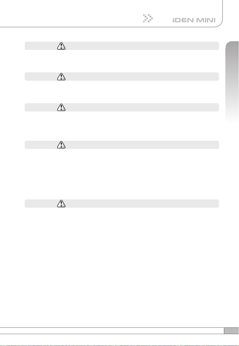
Safety Precautions
Safety Precautions
Warning
Opening the iDEN MINI could result in electric shock and may cause severe injury.
Warning
Connect the equipment frame ground to building ground.
Warning
Operating the iDEN MINI with antennas in very close proximity facing each other
could lead to severe damage to the Booster.
Caution
RF EXPOSURE INFORMATION
A minimum separation distance of 7.9 inches (20cm) must be maintained between
the user and the external antenna of Booster to satisfy FCC RF exposure
requirements. For more information about RF exposure, please visit the FCC
website at www.fcc.gov
Caution
This equipment is for indoor use and enables the communication wiring to
communicate only inside the building.
Page 3
System Manual RSN-iDEN-30-DC
1. Introduction
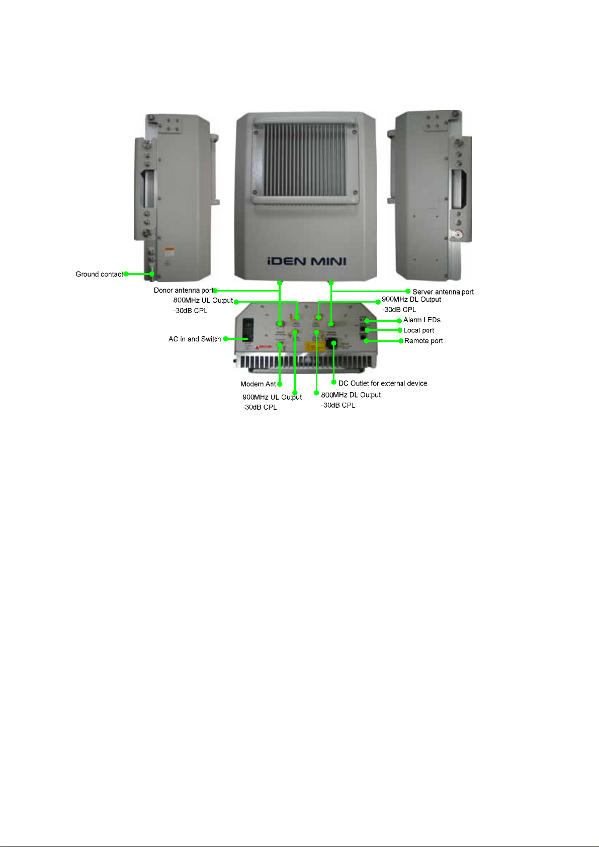
Ground contact
RSN-iDEN-30-DC Booster is used to fill out uncovered areas in iDEN mobile systems, such as
base station fringe areas, road tunnels, business and industrial building s, etc.
An RSN-iDEN-30-DC Booster receives signals from a base station, amplifies and retransmits the
signals to mobile stations. Also it receives, amplifies and retransmits signals in the opposite direction.
Both directions are served simultaneously.
To be able to receive and transmit signals in both directions, the Booster is connected to a donor
antenna directed towards the base station and to a service antenna directed towards the area to
be covered.
Control of the Booster is performed using a desktop or notebook loaded through the RJ-45 Jack
which can communicate with the Booster. Remote operation can be performed.
RSN-iDEN-30-DC Booster work as bi-directional amplifiers.
A Booster receives, amplifies, and retransmits signals inbound and outbound simultaneously, i.e.
from the base station via the Booster to the mobile stations and from the mobile stations via the
R-tron Proprietary & Confidential Page 2
Issue: 1.0
Page 4

System Manual RSN-iDEN-30-DC
Booster
The Booster can be connected to a donor antenna directed towards the base station, and to a
server antenna directed towards the area to be covered. The donor antenna is connected to the
Booster with type-N connector. On the other hand, the server antenna is an external antenna.
The RSN-iDEN-30-DC Booster are controlled by powerful microprocessors. Operational status
LEDs are visible on the bottom of the Booster.
The Booster works with convection cooling without fan because it has a radiator behind the body
of RSN-iDEN-30-DC.
Operational parameters, such as gain, power levels, alarm condition, Automatic Gain Control
condition, etc. are set using a desktop or notebook and the RJ-45 jack, which communicate, either
locally or remotely via the UTP(Unshielded Twisted Pair Wire) cable, with the Booster.
to the base station.
R-tron Proprietary & Confidential Page 3
Issue: 1.0
Page 5
System Manual RSN-iDEN-30-DC
2. System Design
2.1 RSN-iDEN-30-DC Specification
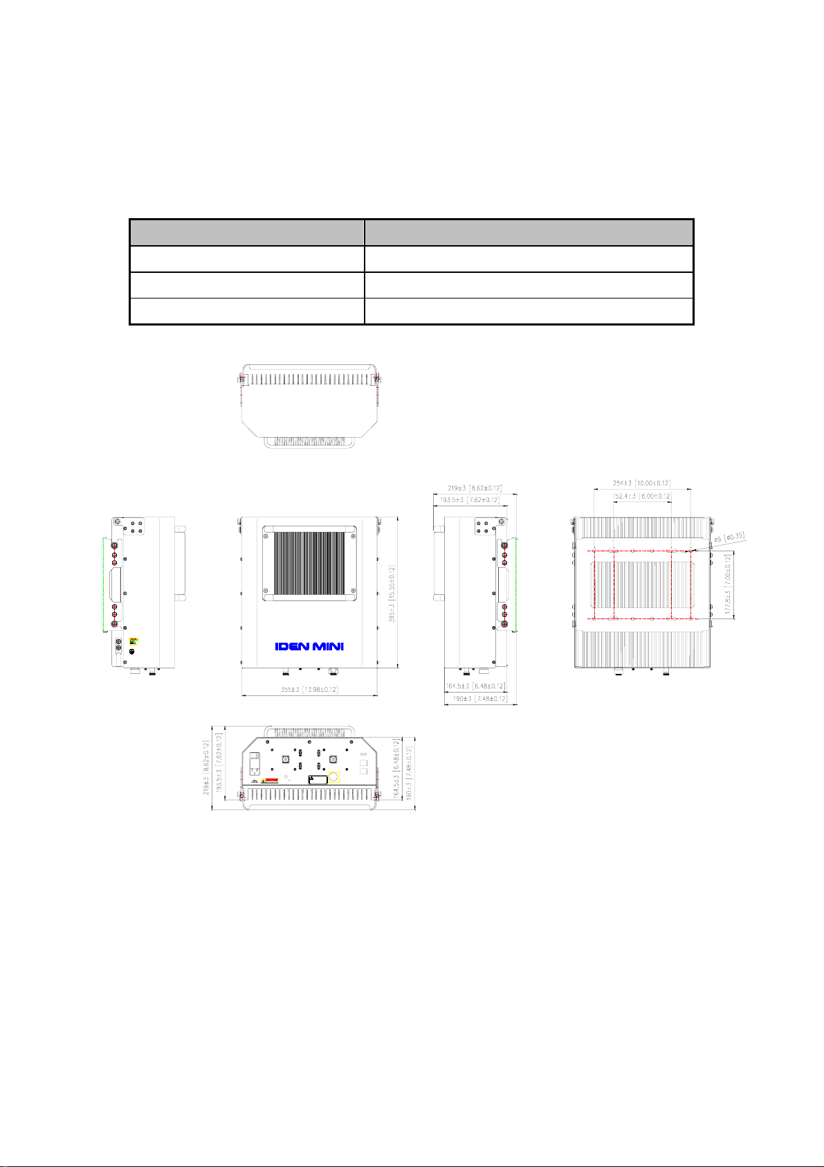
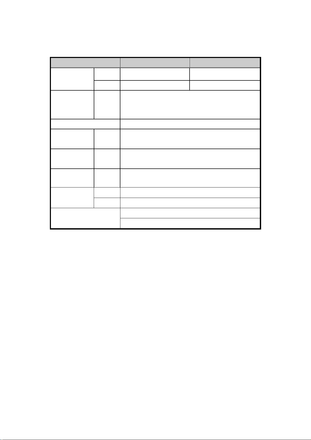
2.1.1 Mechanical Specification
Parameter Specification
RF Ports N-female x 2, SMA-female x 5
Size
13.98 X 15.55 X 7.62(inch), 355 X 395 X 193.5(mm)
Weight 18.56Kg(40.92lbs)
<Table 2-1> Mechanical Specification
800MHz
900MHz
UL Output
DL Output
-30dB CPL.
-30dB CPL.
DONOR
ANTENNA
800MHz
900MHz
DL Output
UL Output
MODEM ANT
-30dB CPL.
AC IN
110 -125Vac
-30dB CPL.
DANGER
RISK OF ELECTRIC SHOCK
Note
Power outlet for compatible
external devices only
ALARM
LOCAL
http://192.168.0.1:83
SERVER
REMOTE
ANTENNA
DC OUT
+12Vdc or -12Vdc
MAX 2A
R-tron Proprietary & Confidential Page 4
Issue: 1.0
Page 6
System Manual RSN-iDEN-30-DC
2.1.2 Electrical & Environmental Specification
A. Spectrum Characteristics
Parameter iDEN 800 iDEN 900
Operating
Frequency
DL 851MHz - 869MHz 935MHz ~ 940MHz
UL 806MHz ~ 824MHz 896MHz ~ 901MHz
≥
65dBc
Roll off
DL & UL
@±500kHz from each edge of operating band
characteristics
(in all temperature)
Flatness
≤
2.5dB (in all temperature)
Gain DL & UL 60dB to 90dB(in all temperature)
Delay DL & UL 8.0µs Max.
VSWR DL & UL 1.5 Max.
Composite
Output Power
UL
Noise Figure
DL 30dBm
UL 30dBm
5dB Max. (@90dB Gain)
12dB Max. (@60dB Gain)
<Table 2-2> RF Specification
R-tron Proprietary & Confidential Page 5
Issue: 1.0
Page 7

System Manual RSN-iDEN-30-DC
B. Environmental specification
Item Standard Remark
Power supply 110V~125V, 60Hz
Operating temperature -10℃ ~ 50℃
Humidity 95 %
<Table 2-3> System Features
R-tron Proprietary & Confidential Page 6
Issue: 1.0
Page 8
System Manual RSN-iDEN-30-DC
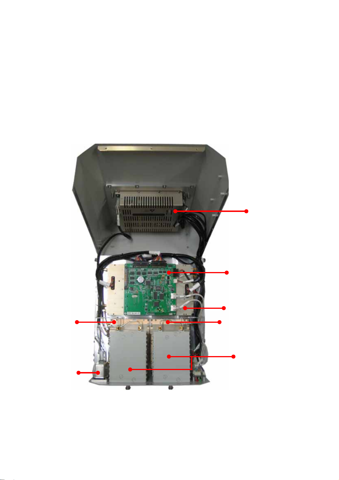
2.2 Sub Unit Overview
RSN-iDEN-30-DC is composed of the following sub units:
UDC(Up Down Converter)
HPAs(High Power Amplifiers)
Multiplexers
Main Control Unit (MCU)
Power Supply Unit (PSU)
EMI Filter
UL HPA
EMI Filter
PSU
MCU
UDC
DL HPA
Multiplexer
R-tron Proprietary & Confidential Page 7
Issue: 1.0
Page 9

System Manual RSN-iDEN-30-DC
2.2.1 Block diagram
The following, Figure explains how the RSN-iDEN-30-DC serves signals.
2.2.2 UDC Modules
The UDC Module is basically a bi-directional amplifier that sharply filters out unwanted noise.
R-tron Proprietary & Confidential Page 8
Issue: 1.0
Page 10

System Manual RSN-iDEN-30-DC
2.2.3 Multiplexers
<Rear view>
<Top view>
<Front view>
R-tron Proprietary & Confidential Page 9
Issue: 1.0
Page 11

System Manual RSN-iDEN-30-DC
2.2.4 Main Control Unit (MCU)
MCU is the control unit of RSN-iDEN-30-DC. It controls and monitors operational parameters.
It also generates alarms, an event log and many other functions of the RSN-iDEN-30-DC.
J10
J9
*Pin Map*
Port Connected to
J6 MCU Vcc(+12V)
J7 Not Available
J8 PSU Alarms / Status LEDs
J9 iDEN 900
J10 iDEN 800
P1 Local
P2 Remote
R-tron Proprietary & Confidential Page 10
Issue: 1.0
Page 12

System Manual RSN-iDEN-30-DC
2.2.5 Power Supply
The Power Supply Unit (PSU) supplies a steady DC power to RSN-iDEN-30-DC by drawing
power from the general in-wall AC outlets
*Specification*
Item Specifications
Operating Temp
Environmental
Voltage AC110~125V
Current 4A Max / 6.5V, 12V, -12V , 27VDC
Frequency 60Hz typ
Leakage Current 0.5mA max.@11 0V AC
Humidity 5%~95%
Cooling method Convection
-10℃~ 50℃
R-tron Proprietary & Confidential Page 11
Issue: 1.0
Page 13

System Manual RSN-iDEN-30-DC
2.2.6 High Power Amplifiers (HPAs)
The High Power Amplifiers the transmitted signal from a base station at the final stage of the
Booster and vice versa.
<iDEN UL HPA>
<iDEN DL HPA>
R-tron Proprietary & Confidential Page 12
Issue: 1.0
Page 14

System Manual RSN-iDEN-30-DC
2.2.6 EMI Noise Filter
2.2.7 Communication & LED Board
R-tron Proprietary & Confidential Page 13
Issue: 1.0
Page 15

System Manual RSN-iDEN-30-DC
* Hardware Installation
1. Setting for Command and Control
* iDEN MINI operates on a customer provided PC based platform with the following system
requirements.
Windows
128 MB RAM or more
Pentium Ⅲ processor or more
RJ-45 jack
Step 1 Open My Network Places.
Step 2 Click the “View network connections”.
®
XP
Strong recommended
keyboard
R-tron Proprietary & Confidential Page 14
Issue: 1.0
Page 16

System Manual RSN-iDEN-30-DC
Step 3 Push the right button of mouse and select the properties.
Step 4 Click the properties of TCP/IP.
R-tron Proprietary & Confidential Page 15
Issue: 1.0
Page 17

System Manual RSN-iDEN-30-DC
Step 5 Set the values and OK as the following. Close all windows.
Step 6 Open a new explorer window.
R-tron Proprietary & Confidential Page 16
Issue: 1.0
Page 18

System Manual RSN-iDEN-30-DC
Step 7 Type http://192.168.0.1:83
in the address box and press “Enter” key.
Step 8 Login with “administrator” of ID and “1234” of password and “OK”.
R-tron Proprietary & Confidential Page 17
Issue: 1.0
Page 19

System Manual RSN-iDEN-30-DC
2. Command and Control on the Web GUI.
A. iDEN 800.
a. To control the iDEN 800, check the box of iDEN 800.
b. The operating bandwidth, 18MHz-bandwidth and 7MHz-band width, is po ssibly sel ected.
Select the operating bandwidth and push the “APPLY” and chec k the ba nd wi dth.
R-tron Proprietary & Confidential Page 18
Issue: 1.0
Page 20

System Manual RSN-iDEN-30-DC
c. The operating frequency is able to be selected. Select the operating frequency and push the
“APPLY” and check the bandwidth and frequency.
R-tron Proprietary & Confidential Page 19
Issue: 1.0
Page 21

System Manual RSN-iDEN-30-DC
B. iDEN 900.
a. To control the iDEN 900, check the box of iDEN 900.
b. On the iDEN 900, 5MHz-bandwith is o nly available.
Select the operating frequency and push the “APPLY” and check the bandwidth a nd freq u ency.
R-tron Proprietary & Confidential Page 20
Issue: 1.0
Page 22

System Manual RSN-iDEN-30-DC
C. DL and UL gain setting.
a. Set the DL gain and UL gain, 50dB to 80dB, and push the “APPLY” button.
* Set the gain of iDEN 900 as same as the iD E N 800 g ain setting.
R-tron Proprietary & Confidential Page 21
Issue: 1.0
Page 23

System Manual RSN-iDEN-30-DC
D. HPA on and off.
a. Press the “ON” and “OFF” and check the status.
The maximum output power for operating is +25dBm on both DL and UL.
R-tron Proprietary & Confidential Page 22
Issue: 1.0
Page 24

System Manual RSN-iDEN-30-DC
* Reference
The Operating Bandwidth & Frequencies
iDEN 800
Bandwidth
18MHz-bandwidth
Operating Frequency
Downlink
Uplink
Downlink
851~869MHz
851~868.8MHz
851~868.6MHz
806~824MHz
806~823.8MHz
806~823.6MHz
862~869MHz
862~868.8MHz
iDEN 900
7MHz-bandwidth
Uplink
Downlink
5MHz-bandwidth
Uplink
Operating bandwidth and Frequencies of iDEN
862~868.6MHz
817~824MHz
817~823.8MHz
817~823.6MHz
935~940MHz
935~939.8MHz
935~939.6MHz
896~901MHz
896~900.8MHz
896~900.6MHz
R-tron Proprietary & Confidential Page 23
Issue: 1.0
 Loading...