

Page 1
iDEN MINI
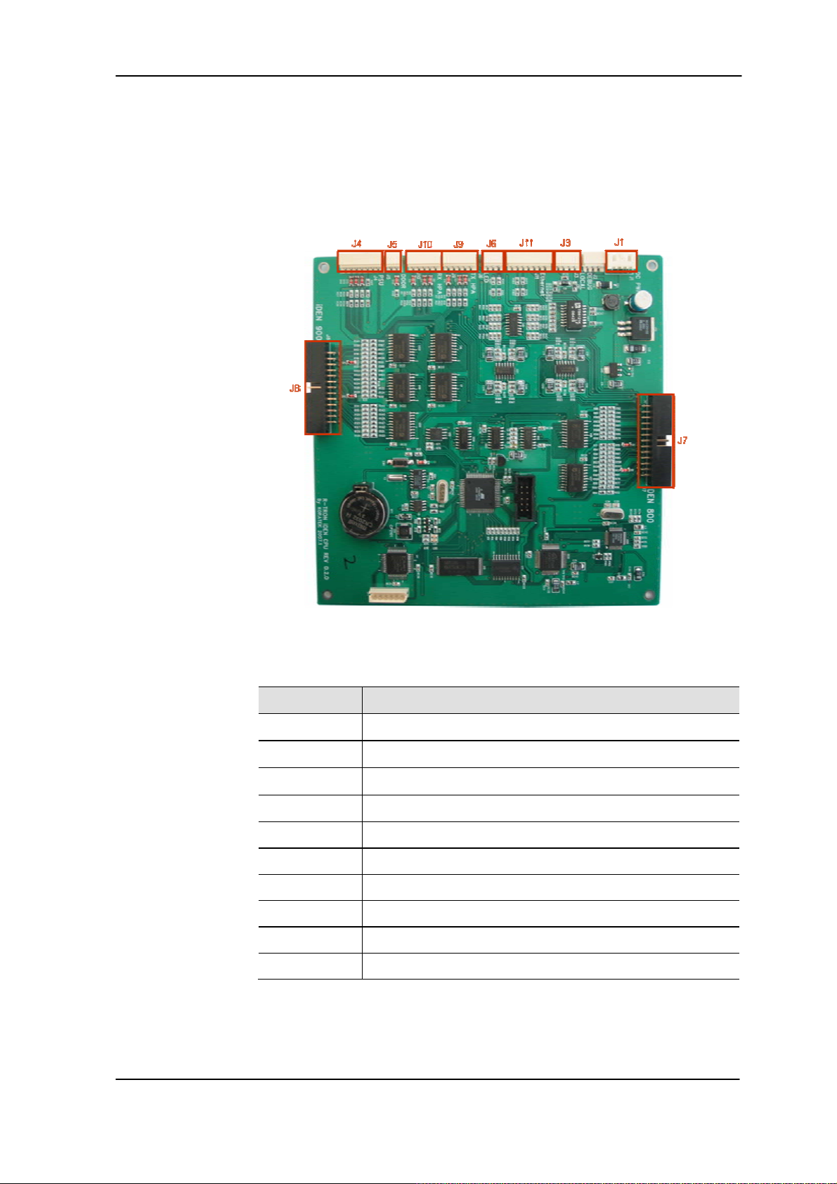
2.2.4. MCU (Main Control Unit)
MCU is the control unit of iDEN MINI. It controls and monitors operational
parameters. It also generates alarms, an event log and many other
functions of the iDEN MINI.
Figure 8. Main Control Unit
Pin Map
Port Connected to
J1 MCU Vcc(+12V)
J3 USB Port(Manufacturer use only)
J4 PSU Alarms
J5 Door Alarm
J6 Status LEDs
J7 iDEN 800 PLL,B/S,OUT DET
J8 iDEN 900 PLL,B/S,OUT DET
J9 Tx HPA
J10 Rx HPA
J11 RJ-45 port
User’s Manual -15-
Page 2
iDEN MINI
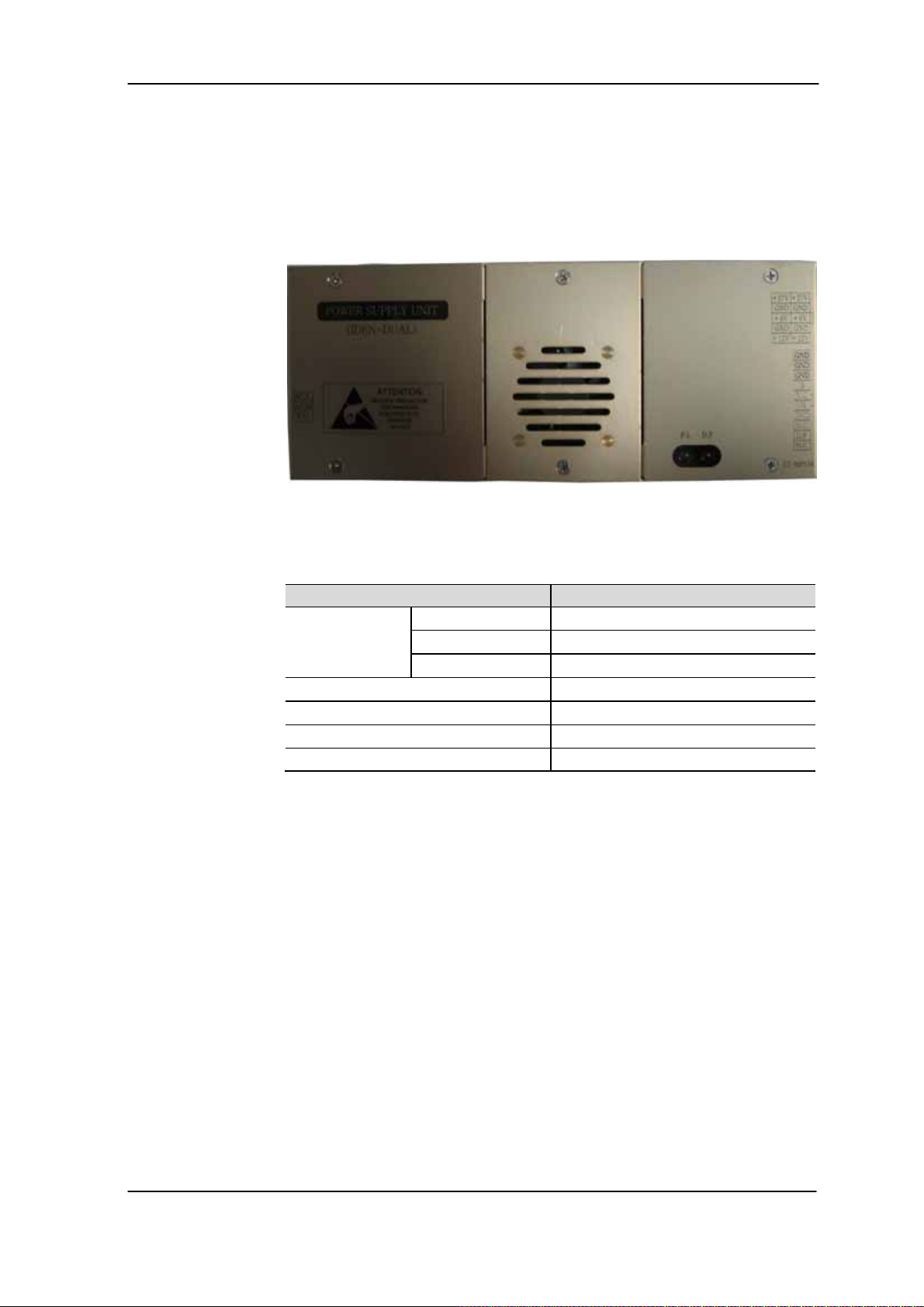
2.2.5. Power Supply
The Power Supply Unit (PSU) supplies a steady DC power to iDEN MINI
by drawing power from the general in-wall AC outlets.
Figure 9. Power Supply
Specifications
Environmental
Item Specifications
Operating Temp -10°C~50°C/14°F~122°F
Humidity 20%~90%RH
Cooling method Natural air
Voltage AC110~125V
Current 6A Max / 6V, 12V, 27VDC
Frequency 50~60Hz typ
Leakage Current 0.5mA max.@110V AC
User’s Manual -16-
Page 3

iDEN MINI
2.2.6. HPAs (High Power Amplifiers)
The High Power Amplifiers (HPAs) amplifies the transmitted signal from
a base station at the final stage of the repeater and vice versa.
Figure 10. HPAs(High Power Amplifiers)
User’s Manual -17-
Page 4
iDEN MINI
3. Hardware Installation
The installation procedure is as follows:
Check List of Items
Mounting
Grounding
RF Connection
Power up
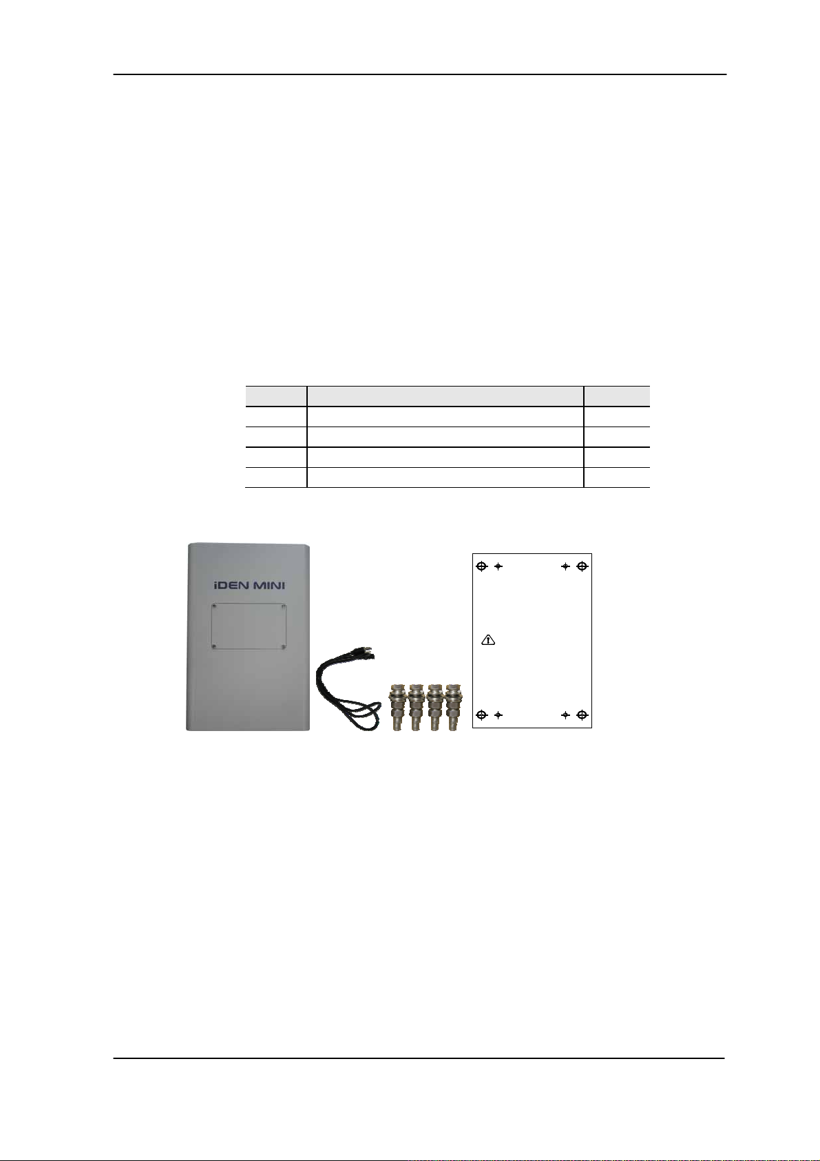
3.1 Check List of Items
Index Items Q’ty
1 iDEN MINI 1
2 Power Cord 1
3 Screws for Mounting 4
4 Template for marking of the pilot holes 1
Items
1
A-TYPE A-TYPE
2
3
Figure 11. Items
Use this tem p late to m ark
the location for pilot holes
B-TYPE B-TYPE
4
B-TYPEB-TYPE
A-TYPEA-TYPE
User’s Manual -18-
Page 5

iDEN MINI
3.2 Mounting
iDEN MINI is easy to mount using the assembled mounting bracket,
which has Ø9 holes for the provided 5/16" fixing screws.
Figure 12. Mounting
Step 1. Remove the cover of double-coated foam tape squares at each corner on
the back side of the template.
Step 2. Stick the provided template to the wall using the tape squares while
adjusting the horizon.
Step 3. Mark with a pen for the holes and drill the marks or drill holes directly on
the mark in the template.
Step 4. Put the screws or bolts into the holes.
Step 5. Mount the iDEN MINI on the right position.
CAUTION
Firmly affix the equipment on the wall of a building and Check necessary.
User’s Manual -19-
Page 6

iDEN MINI
quip
3.3 Grounding
WARNING
Dangerously high voltages may occur and damage the equipment if the
ment is not groundedproperly.
e
A rod on the left side is intended for a building ground. Connect the ground
cable to the rod.
3.4 RF Cable Connection
a. Connect a cable from a donor antenna to the DONOR ANTENNA Port.
b. Connect a cable from the SERVICE ANTENNA Port to a repeater’s
service antenna.
Figure 13. Grounding
User’s Manual -20-
Page 7

iDEN MINI
Base
Station
3.5 Power Up
Donor
antenna
Plugged in an
AC outlet
Repeater
Donor Service
Figure 14. Configuration: RF Cable Connection
a. Connect the power cord.
b. Plug the power cord into a wall outlet.
c. Check if the green LED at the bottom turns on.
Service
antenna
Mobile Station
Figure 15. Power Cord Connection
User’s Manual -21-
Page 8

iDEN MINI
4. Command and Control through the Hyper Terminal
4.1 Setting for Command and Control through the Hyper Terminal
Figure 16. Local connection to the iDEN MINI
* iDEN MINI operates on a customer provided PC based platform with the following system
requirements.
Windows® 2000 or Windows® XP
128 MB RAM or more
Pentium Ⅲ processor or more
RJ-45 jack
Step 1 Open My Network Places.
keyboard
User’s Manual -22-
Page 9

iDEN MINI
Step 2 Click the “View network connections”.
Step 3 Push the right button of mouse and select the properties.
User’s Manual -23-
Page 10

iDEN MINI
Step 4 Click the properties of TCP/IP.
Step 5 Set the values and OK as the following. Close all windows.
User’s Manual -24-
Page 11

iDEN MINI
Step 6 Execute the Hyper Terminal.
Step 7 Name the session and OK.
Step 8 Select the TCP/IP (Winsock).
User’s Manual -25-
Page 12

iDEN MINI
Step 9 Set the values as the following and OK.
4.2 Command and Control through the Hyper Terminal
Step 1. To see the current status, hit “Enter” key only.
User’s Manual -26-
 Loading...