

Page 1
CDMA MINI
CDMA MINI
(RSN-CDMA-30-C)
User’s Manual
R-tron Inc.
User’s Manual -1-
Page 2

CDMA MINI
CAUTION
This equipment is indoor use and all the communication
User’s Manual -2-
Page 3

CDMA MINI
This document describes the specifications, installation and operation of CDMA MINI.
Hardware and software mentioned in this document are subject to continuous development and
improvement. Consequently, there may be minor discrepancies between the information in the
document and the performance and design of the product. Specifications, dimensions and other
statements mentioned in this document are subject to change without notice.
R-tron Inc. 6402 College Boulevard Overland Park, KS 66211
Phone: +1-913-344-9977, 1-888-31R-TRON Fax: +1-913-344-9988 Internet: www.r-
tron.com
R-tron is registered trademarks of R-tron Inc. Other products and company names mentioned herein this
manual might be trade marks or trade names of their respective owners.
This document or parts of it may not be reproduced without the written permission of R-tron Inc.
Infringements will be prosecuted. All rights reserved
Copyright © R-tron Inc. 2000-2007
User’s Manual -3-
Page 4

CDMA MINI
Contents
Abbreviations ................................................................................................... 5
1. Introduction .................................................................................................. 6
2. Description .................................................................................................... 8
2.1 System Specifications ........................................................................................ 8
2.1.1 Electrical Specifications ......................................................................................... 8
2.1.2 Mechanical Specifications ...................................................................................... 9
2.2 Sub Unit Overview ........................................................................................... 10
2.2.1 Block diagram ...................................................................................................... 11
2.2.2 UDC Module ........................................................................................................ 12
2.2.3 Duplexer ............................................................................................................... 13
2.2.4 Main Control Unit (MCU) ..................................................................................... 14
2.2.5 Power Supply ....................................................................................................... 15
2.2.6 High Power Amplifier (HPA) ................................................................................. 16
3. Hardware Installation ................................................................................. 17
3.1 Check List of items ........................................................................................... 17
3.2 Mounting .......................................................................................................... 18
3.3 Grounding ........................................................................................................ 21
3.4 RF Cable Connection ....................................................................................... 22
3.5 Power Up ......................................................................................................... 22
4. Command and Control through the Hyper Terminal ............................... 23
4.1 Setting for Command and Control through the Web GUI…………………...……………
23
5. Command and Control on the Web GUI……………………………………..26
5.1 DL and UL Bandwidth Selection…………………………………………………………...…27
5.2 DL and UL DL and UL gain setting
5.3 HPA On and OFF
………………………………………………………………....29
………………………………………………....28
6. Troubleshooting ......................................................................................... 30
6.1 RF Connection check ....................................................................................... 30
6.2 Power Connection ............................................................................................ 30
6.3 Red Light on the Alarm LED ............................................................................. 30
User’s Manual -4-
Page 5

CDMA MINI
Abbreviations
Abbreviations used in this manual, in iDEN Add-On Filter Box.
AC Alternating Current
ANT Antenna
CDMA Code Division Multiple Access
DC Direct Current
GND Grounding
GUI Graphic User Interface
LED Light Emitting Diode
PSU Power Supply Unit
MCU Main Control Unit
UDC Up Down Converter
RF Radio Frequency
TEMP Temperature
VSWR Voltage Standing Wave Ratio
User’s Manual -5-
Page 6
p
p
CDMA MINI
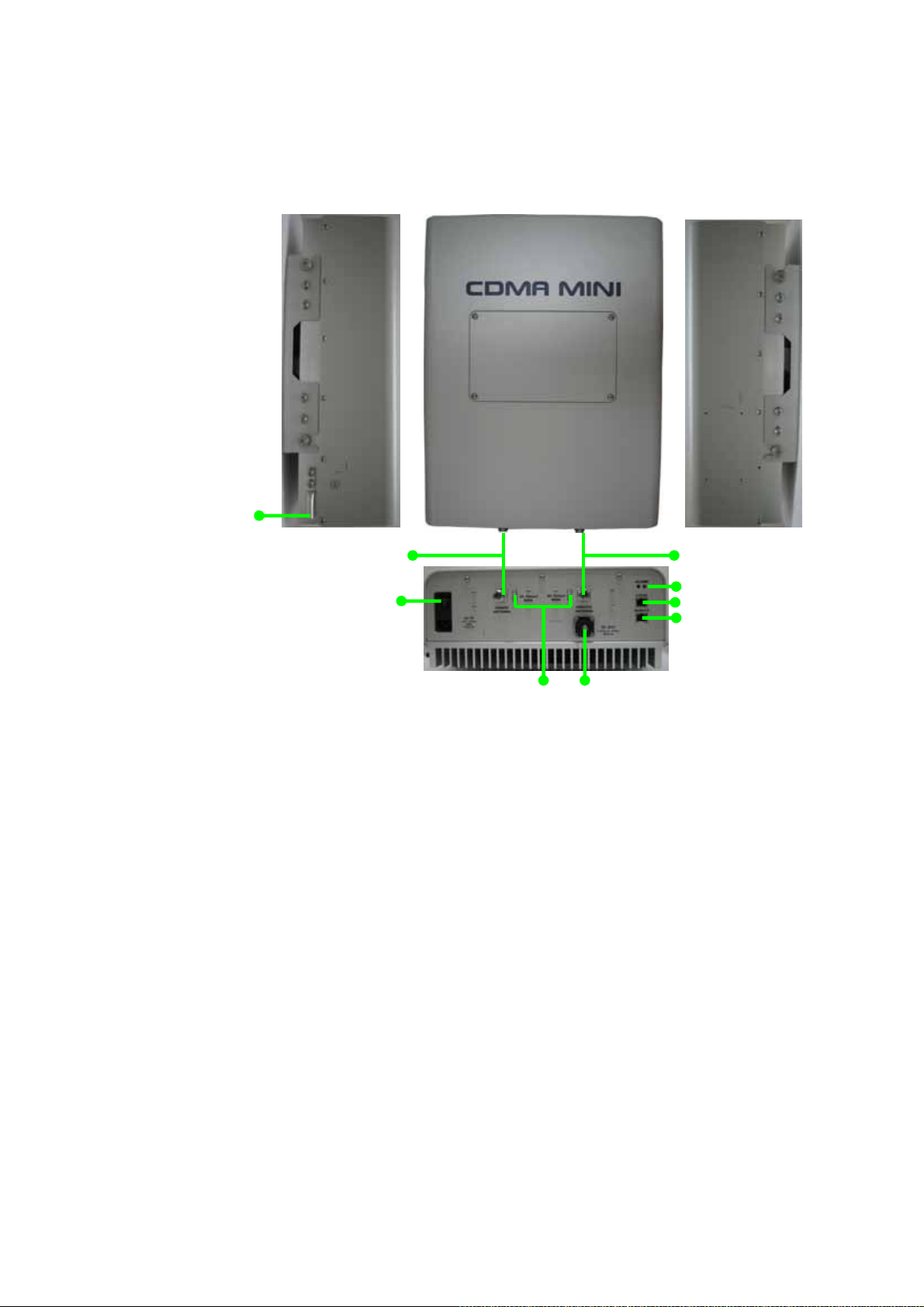
1. Introduction
Ground contact
Donor antenna port
AC in and Switch
DL and UL output monitoring
DC Outlet for external device
Alarm LEDs
Local
ort
Remote
ort
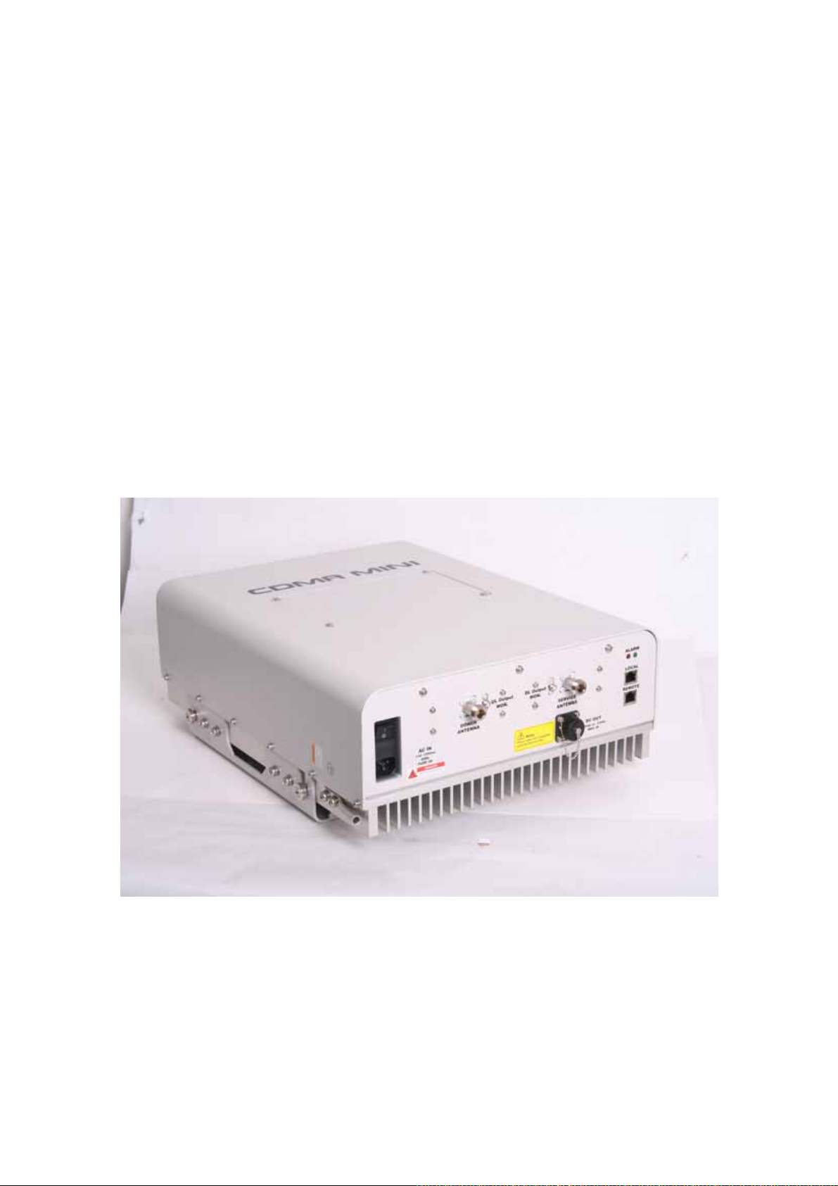
CDMA MINI repeater is used to fill out areas in CDMA mobile systems, such as base station
fringe areas, business and industrial buildings, etc.
CDMA MINI receives signals from a base station, amplifies and retransmits the signals to
mobile stations. Also it receives, amplifies and retransmits signals in the opposite direction. Both
directions are served simultaneously with the following features:
65MHz bandwidth service
Band Selection (5MHz , 10MHz , 15MHz , 20MHz , 5MHz+5MHz , 10MHz+5MHz,
15MHz+5MHz , 20MHz+5MHz , 5MHz+5MHz+5MHz) service
Roll Offs: 65 dBc at 1 MHz outside pass-band
The RSN-CDMA-30-C Repeaters are controlled by powerful microprocessors. Operational
status LEDs are visible on the bottom of the repeater.
The repeater works with convection cooling without fan because it has a radiator behind the
User’s Manual -6-
Page 7

CDMA MINI
body of RSN-CDMA-30-C.
Operational parameters, such as gain, power levels, alarm condition, Automatic Gain Control
condition, etc. are set using a desktop or notebook and the Hyper Terminal, which communicate,
either locally or remotely via the UTP(Unshielded Twisted Pair Wire) cable, with the repeater.
Caution
RF EXPOSURE INFORMATION
Caution RF EXPOSURE INFORMATION a minimum separation distance of 7.9 inches
(20cm) must be maintained between the user and the external antenna of repeater to
satisfy FCC RF exposure requirements For more information about RF exposure, please
visit the FCC
Website at www.fcc.gov
User’s Manual -7-
Page 8
CDMA MINI
2. Description
2.1 System Specifications
2.1.1 Electrical Specifications
Parameter Down Link Up Link
Operating Frequency 1930MHz~1995MHz 1850MHz~1915MHz
Gain 50dB to 90dB
Roll off ≤50dBc @Fedge+/-1MHz
Gain ripple ±1.5dB
Delay 5.0uS Max
VSWR 1.5Max
Rating(s)
Operating temperature -10℃~ 45℃
Storage temperature -20℃~ 60℃
Band Selection
Input: 110Vac ~ 125Vac, 60Hz, 2.0A
Output: +12Vdc or -12Vdc / Max. 2.0A
5MHz , 10MHz , 15MHz , 20MHz
5+5MHz , 10+5MHz , 15+5MHz , 20+5MHz
5+5+5MHz
User’s Manual -8-
Page 9
CDMA MINI
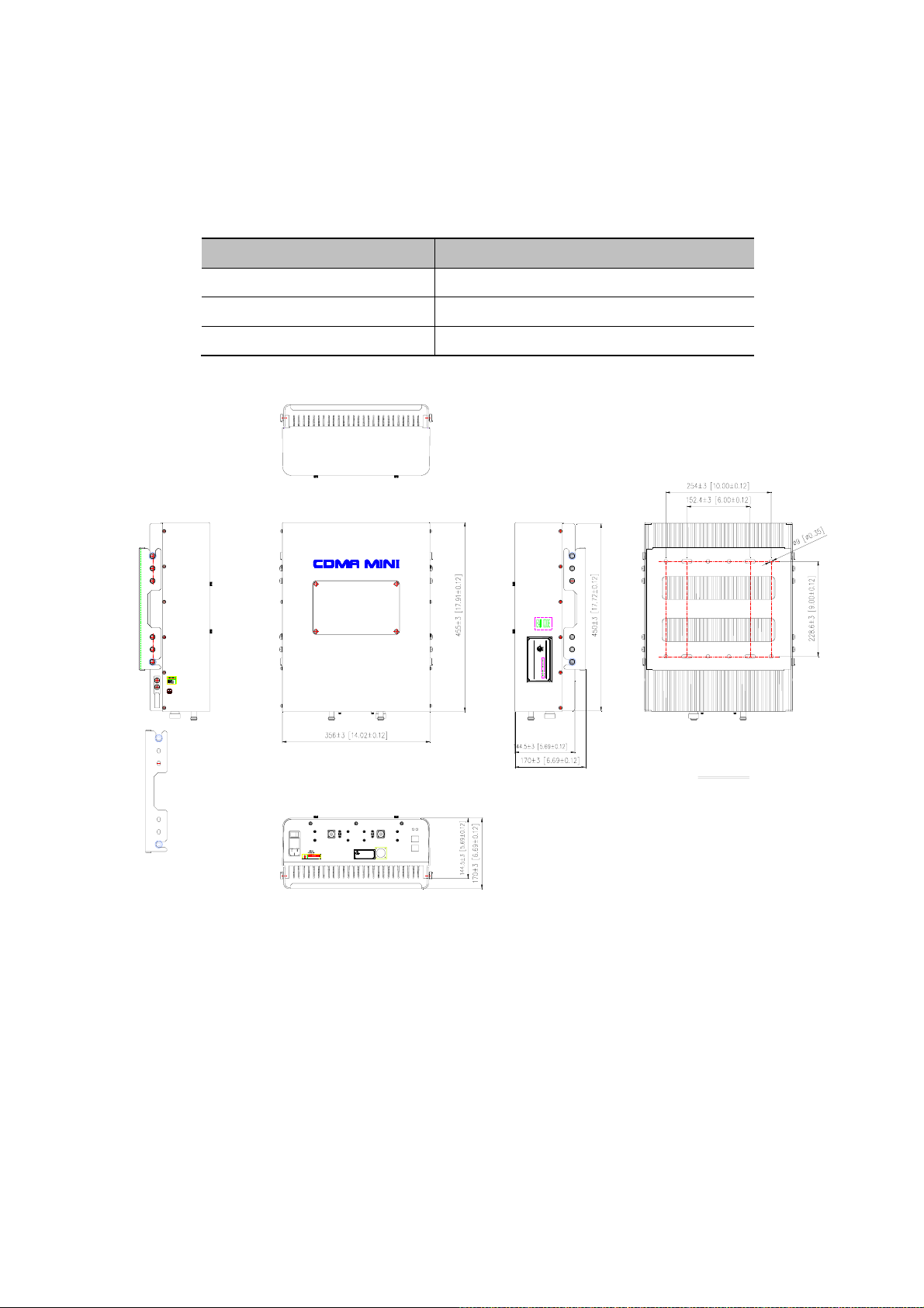
2.1.2 Mechanical Specifications
Parameter Specification
RF connectors N-female x 2, SMA-female x 2
Size 14 X17.9 X 6.7(Inch), 356 X 455 X 170(mm)
Weight 20kg (44.1lbs)
I.T.E
31CY
E258109
MADE IN KOREA
RSN-iDEN-30
:PRODUCT PART NUMBER
110 -125V ~ , 60Hz , 4A
R-tron lnc.
:MAKER
may not harmful interference.
Operation is subject to the condition that this device
This device complies with Part 15 of the FCC Rules.
COMPLIES WITH PART 90, FCC RULES.
POWER :
FCC REG. NO. : STESNiDEN30
SERIAL NO. / DATE :
BRACKET
ALARM
110 -125Vac
DANGER
RISK OF ELECTRIC SHOCK
Note
Power outlet for compatible
external devices only
DL Output
UL Output
MON.
MON.
DONOR
ANTENNA
AC IN
LOCAL
SERVICE
REMOTE
ANTENNA
DC OUT
+12Vdc or -12Vdc
MAX 2A
User’s Manual -9-
Page 10
CDMA MINI
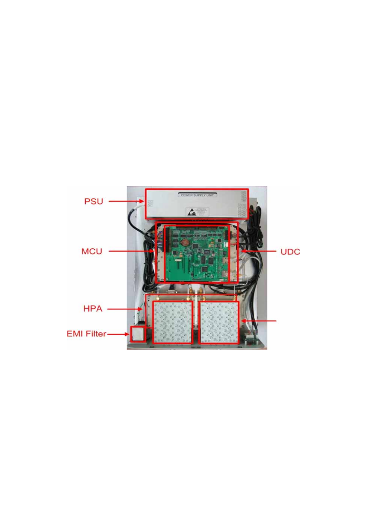
2.2 Sub Unit Overview
CDMA MINI is composed of the following sub units:
UDC(Up Down Converter)
HPAs(High Power Amplifiers)
Duplexer
Main Control Unit (MCU)
Power Supply Unit (PSU)
EMI Filter
Duplexer
User’s Manual -10-
Page 11

CDMA MINI
2.2.1 Block diagram
The following, Figure explains how the CDMA MINI serves signals.
Donor
antenna
Duplexer
S/W
AMP
3-Way
S/W
3-Way
S/W
3-Way
S/W
AMP
3-Way
Duplexer
Service
antenna
User’s Manual -11-
Page 12

CDMA MINI
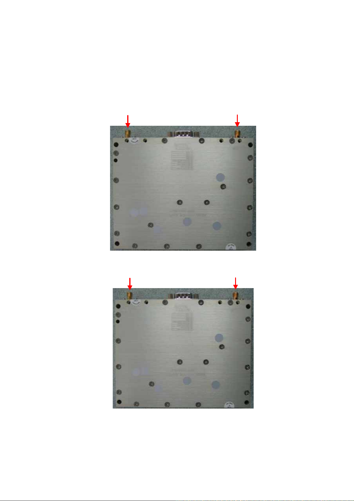
2.2.2 UDC Module
The UDC Module is basically a bi-directional amplifier that sharply filters out
unwanted noise.
<UDC Module DL>
<UDC Module UL>
User’s Manual -12-
Page 13

CDMA MINI
2.2.3 Duplexer
A multiplexer is a device that combines two or more signals onto a common
channel or medium to increase its transmission efficiency.
User’s Manual -13-
Page 14

CDMA MINI
2.2.4 Main Control Unit (MCU)
MCU is the control unit of CDMA MINI. It controls and monitors operational parameters.
It also generates alarms, an event log and many other functions of the CDMA MINI.
*Pin Map*
Port Connected to
J6 MCU Vcc(+12V)
J7 CDMA DL,UL Control Pin
J8 PSU Alarms / Status LEDs
P1 Local
P2 Remote
User’s Manual -14-
Page 15

CDMA MINI
2.2.5 Power Supply
The Power Supply Unit (PSU) supplies a steady DC power to CDMA MINI by drawing
power from the general in-wall AC outlets
*Specification*
Environmental
Leakage Current 0.5mA max.@110V AC
Item Specifications
Operating Temp
-10℃~50℃
Humidity 20%~90%RH
Cooling method Natural air
Rated Input: 110~125Vac, 60Hz, 2.0A
Rated Output: +27Vdc, 2.0A /
Rating(s)
+6Vdc, 5.0A / +12Vdc, 3.0A /
-12Vdc, 2.0A
User’s Manual -15-
Page 16
CDMA MINI
2.2.6 High Power Amplifier (HPA)
The High Power Amplifiers the transmitted signal from a base station at the final
stage of the repeater and vice versa.
RF Input RF Output
<Tx HPA>
RF Input RF Output
<Rx HPA>
User’s Manual -16-
Page 17
CDMA MINI
3. Hardware Installation
The installation procedure is as follows:
Check List of Items
Mounting
Grounding
RF Connection
Power up
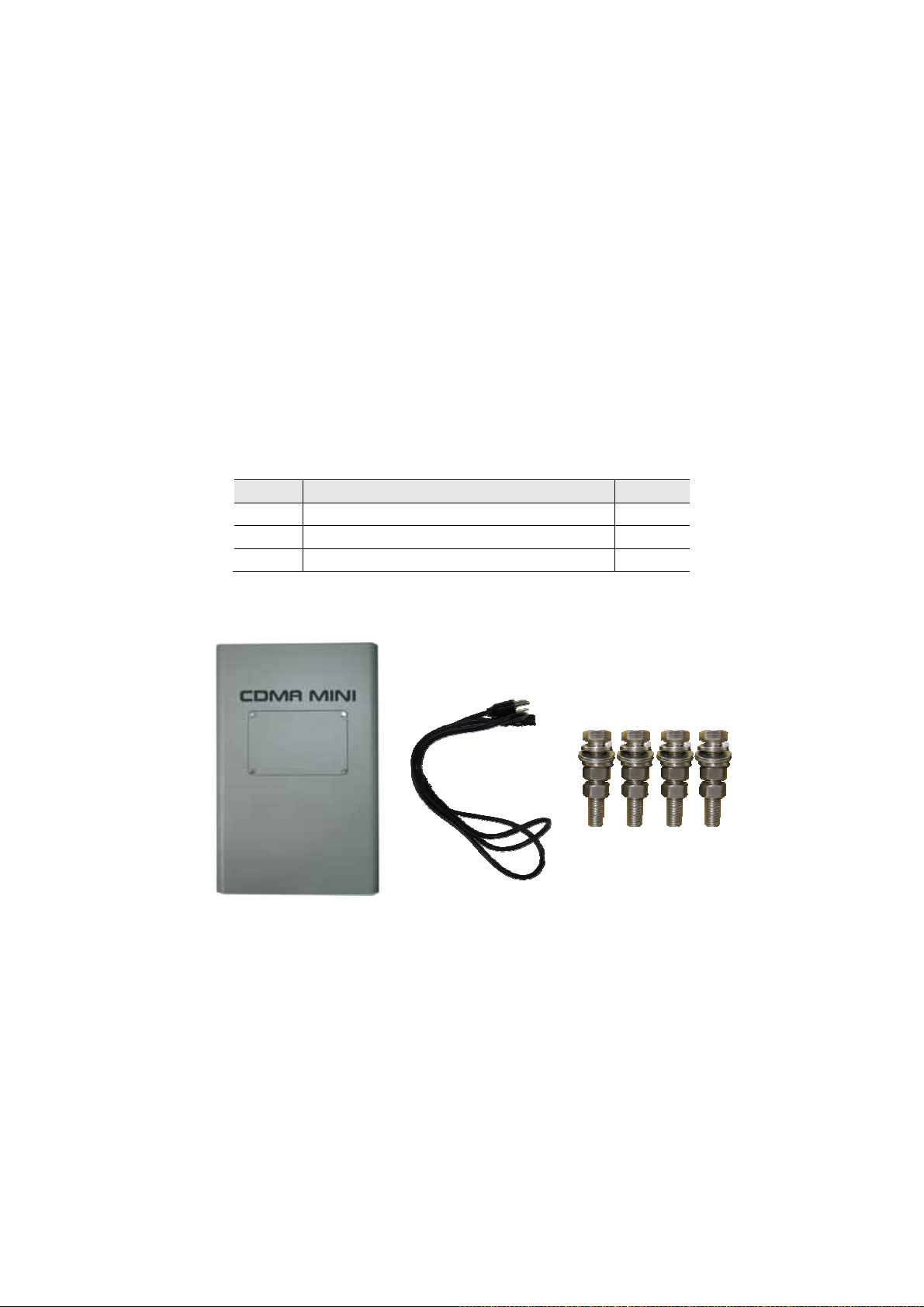
3.1 Check List of items
Index Items Q’ty
1 CDMA MINI 1
2 Power Cord 1
3 Screws for Mounting 4
1 2
User’s Manual -17-
3
Page 18
CDMA MINI
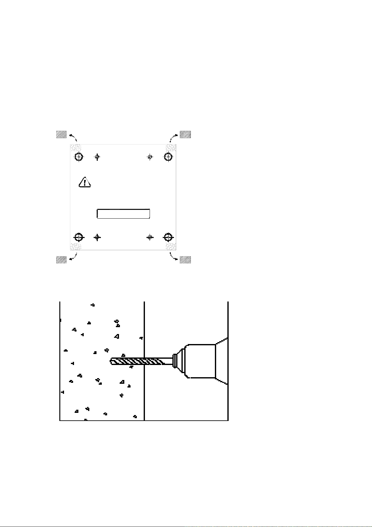
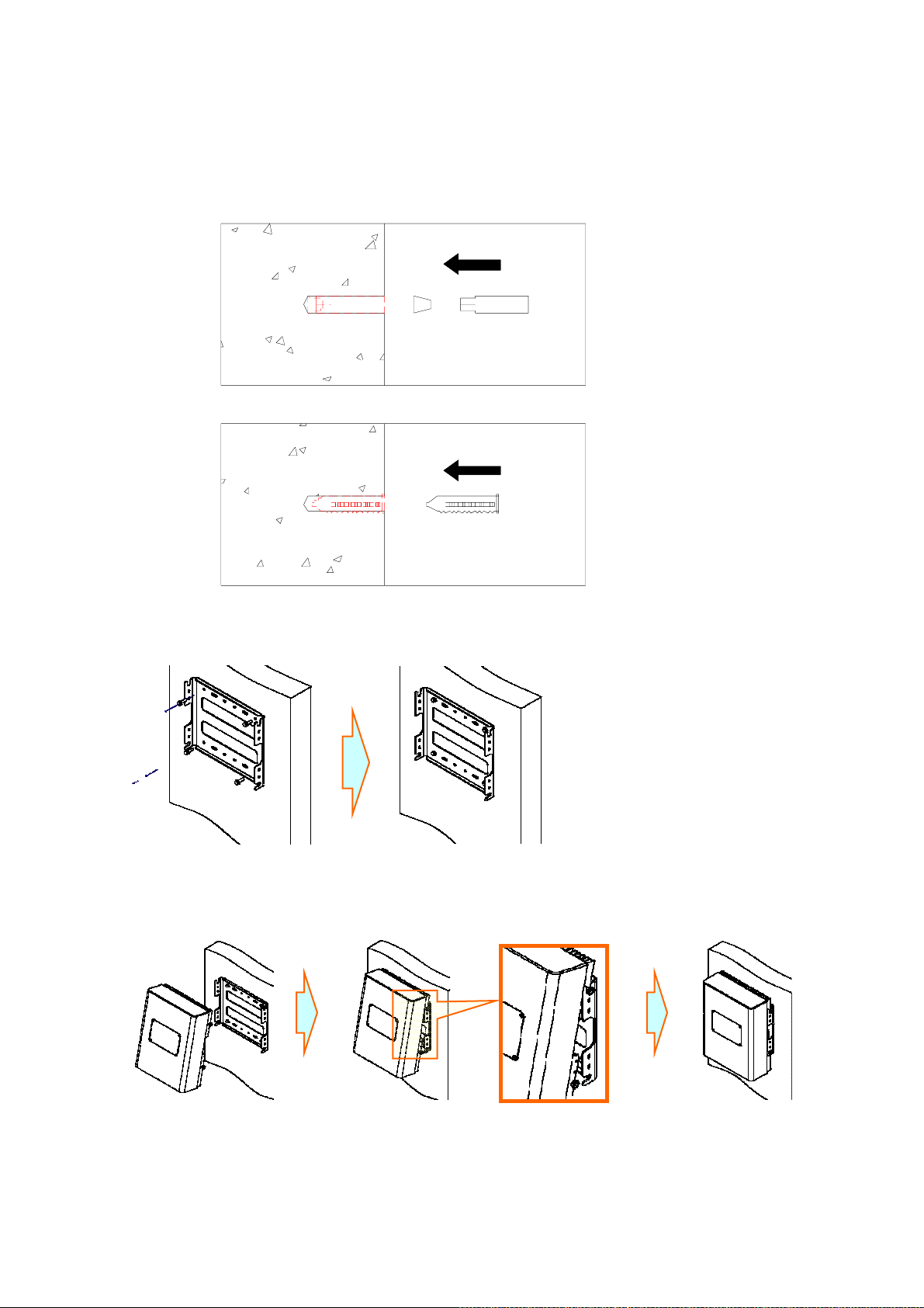
3.2 Mounting
CDMA MINI is easy to mount using the assembled mounting bracket, which has Ø9
holes for the provided 5/16" fixing screws.
Step 1.
A-TYPE
A-TYPE
Step 2.
B-TYPE
Use this templa te t o mark
the locat ion for pilot holes
I NSTAL L RSN -C30-C
A-TYPE : 254 [10.00] x 228.6 [9.00]
B-T YPE : 152.4 [6.00] x 228.6 [9.00]
B-TYPE
B-TYPE
B-TYPE
A-T Y PE
A-T Y PE
User’s Manual -18-
Page 19
CDMA MINI
Step 3.
Step 4.
Step 5.
User’s Manual -19-
Page 20
CDMA MINI
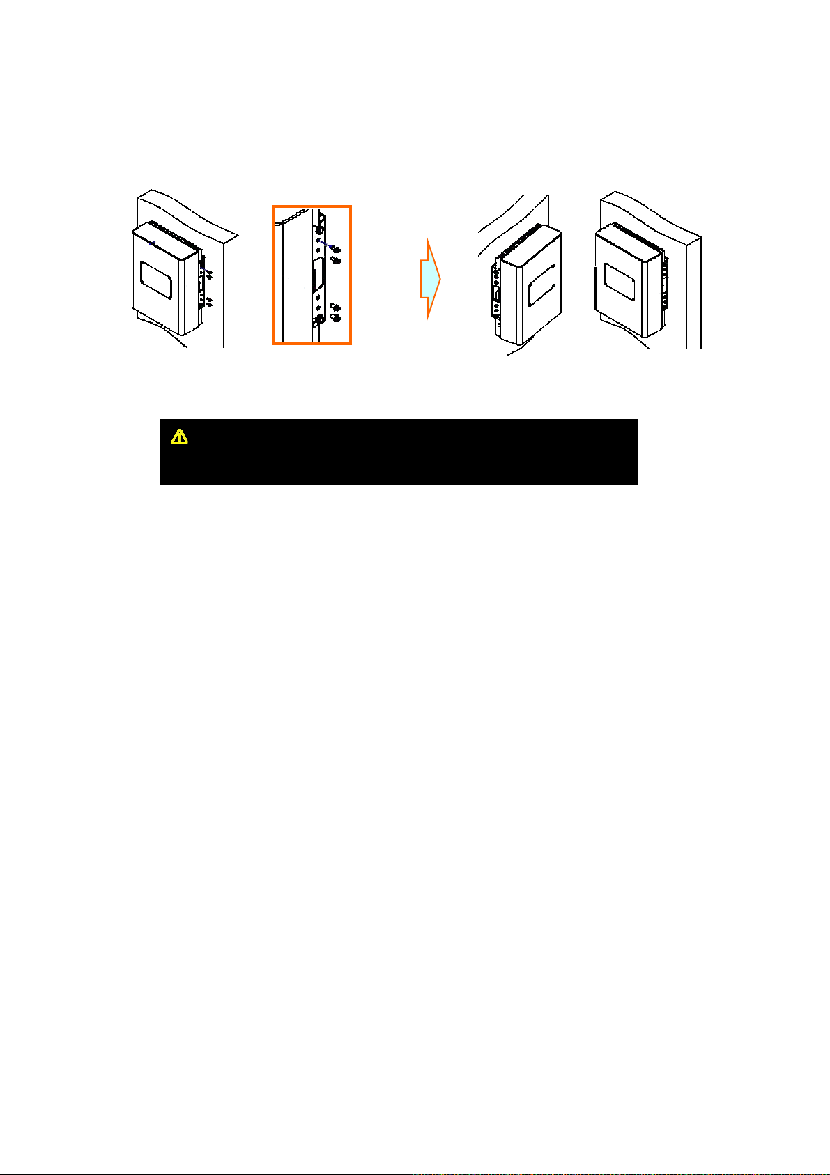
Step 6.
CAUTION
Firmly affix the equipment on the wall of a building and Check necessary.
User’s Manual -20-
Page 21
CDMA MINI
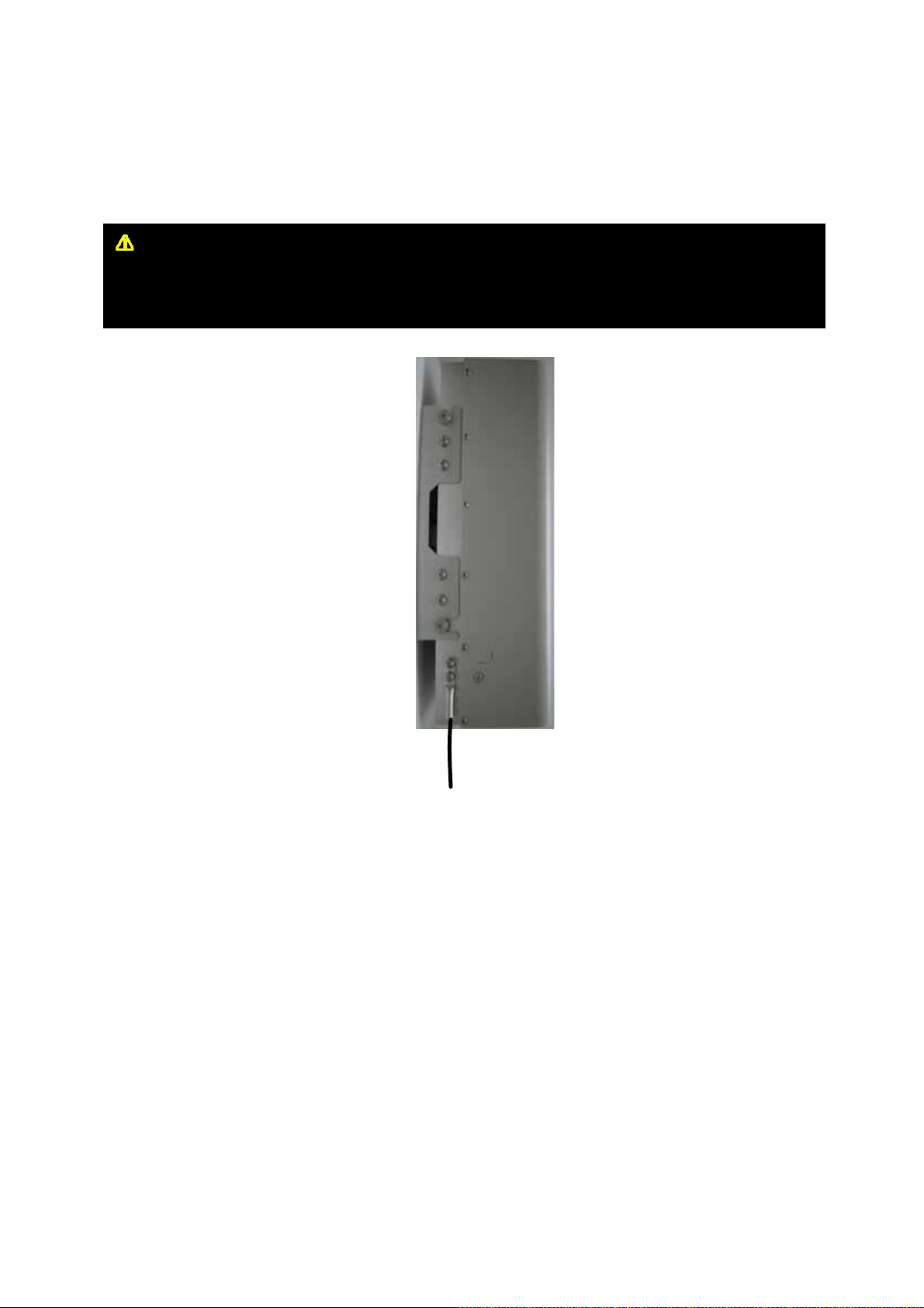
3.3 Grounding
WARNING
Dangerously high voltages may occur and damage the equipment if the equipment is not grounded
properly.
A rod on the left side is intended for a building ground. Connect the ground cable to the
rod.
User’s Manual -21-
Page 22
CDMA MINI
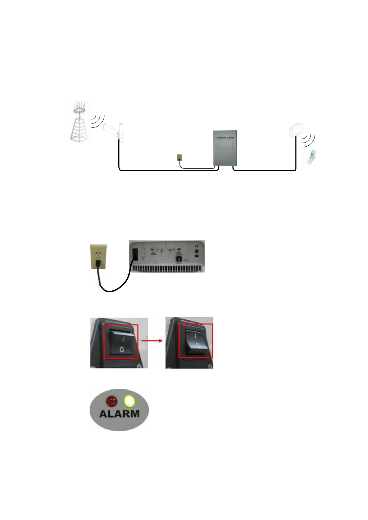
3.4 RF Cable Connection
a. Connect a cable from a donor antenna to the DONOR ANTENNA Port.
b. Connect a cable from the SERVICE ANTENNA Port to a repeater’s service antenna.
Base St at ion
3.5 Power Up
a. Connect the power cord.
b. Plug the power cord into a wall outlet.
Donor
antenna
Service
antenna
Repeater
Plugged
AC outlet
Mobile Station
Donor Service
c. Switch on.
d. Check if the green LED at the bottom turns on.
User’s Manual -22-
Page 23
CDMA MINI
4. Command and Control through the Hyper Terminal
4.1 Setting for Command and Control through the Web GUI
* CDMA MINI operates on a customer provided PC based platform with the following system
requirements.
Windows® XP
128 MB RAM or more
Pentium Ⅲ processor or more
RJ-45 jack
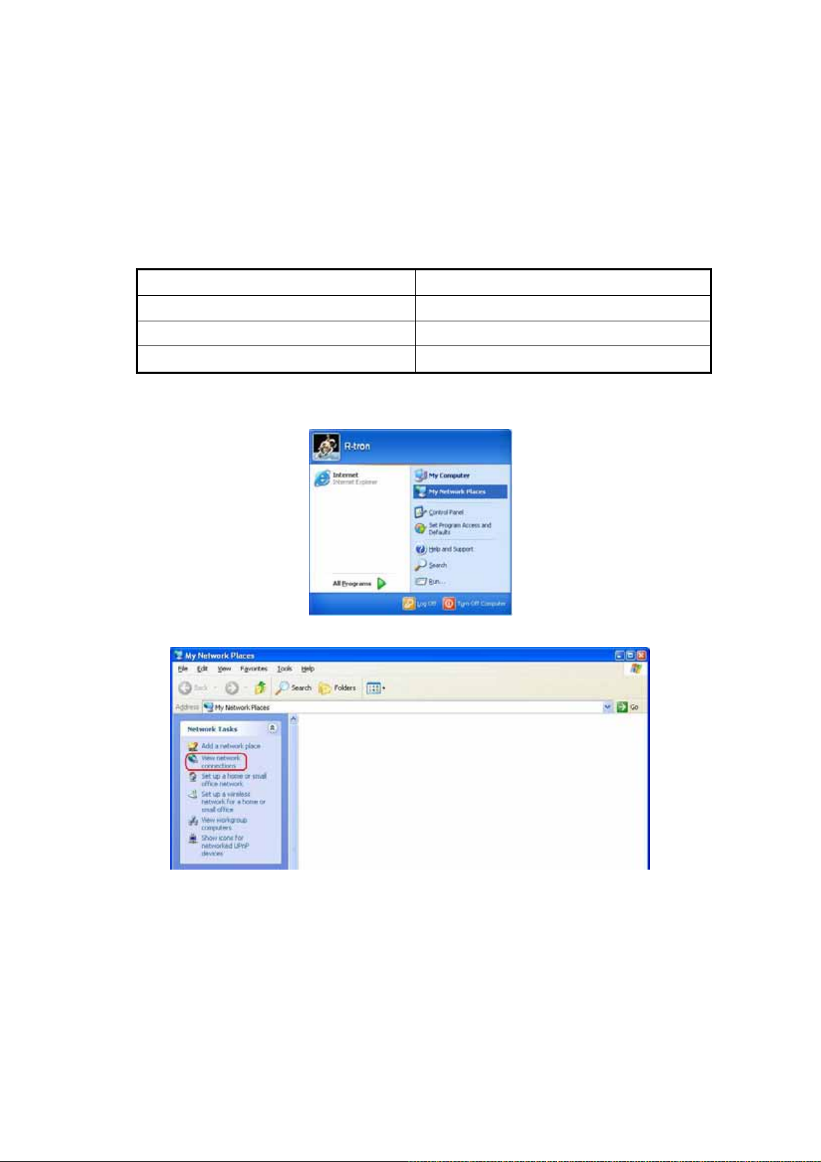
Step 1 Open My Network Places.
Step 2 Click the “View network connections”.
Strong recommended
keyboard
User’s Manual -23-
Page 24
CDMA MINI
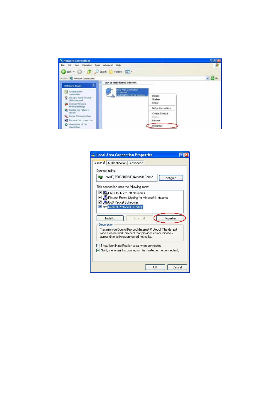
Step 3 Push the right button of mouse and select the properties.
Step 4 Click the properties of TCP/IP.
User’s Manual -24-
Page 25
CDMA MINI
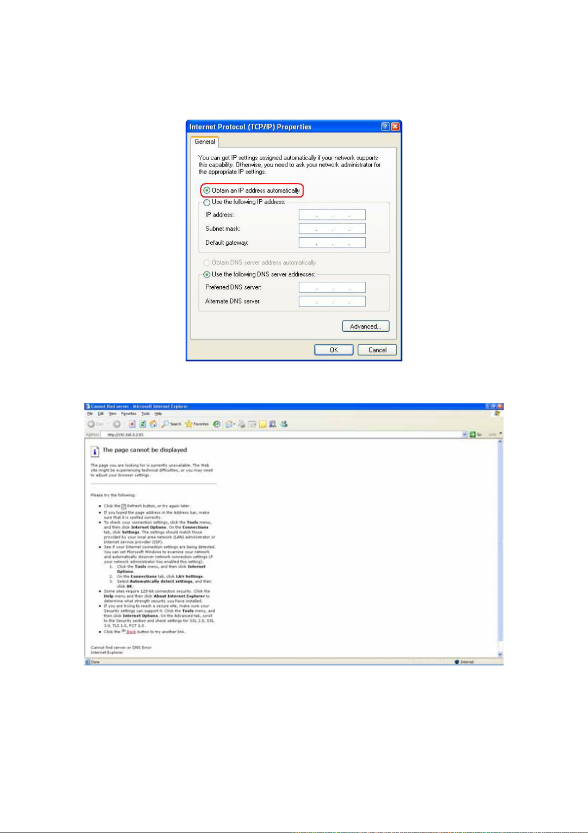
Step 5 Set the values and OK as the following. Close all windows.
Step 6 Open a new explorer window.
User’s Manual -25-
Page 26

CDMA MINI
Step 7 Type http://192.168.0.2:83
in the address box and press “Enter” key.
Step 8 Login with “admin” of ID and “1234” of password and “OK”.
User’s Manual -26-
Page 27

CDMA MINI
5. Command and Control on the Web GUI
5.1 DL and UL Bandwidth Selection
a. To control the CDMA MINI, check the box of PCS 1900.
b. The operating bandwidth,5MHz,10MHz,15MHz,20MHz,5+5MHz,10+5MHz,15+5MHz,
20+5MHz, 5+5+5MHz bandwidth is possibly selected.
Select the operating bandwidth and push the “APPLY” and check the bandwidth.
User’s Manual -27-
Page 28

CDMA MINI
c. The operating frequency is able to be selected. Select the operating frequency and push the
“APPLY” and check the bandwidth and frequency.
5.2 DL and UL DL and UL gain setting
a. Set the DL gain and UL gain, 50dB to 90dB, and push the “APPLY” button.
User’s Manual -28-
Page 29

CDMA MINI
5.3 HPA On and OFF
a. Press the “ON” and “OFF” and check the status.
The maximum output power for operating is +30dBm on both DL
and UL.
User’s Manual -29-
Page 30

CDMA MINI
6. Troubleshooting
6.1 RF Connection check
<Problem>
Either the downlink output power or the uplink output power (=Input Power to the repeater)
is too weak.
<Solution>
Check if the following RF connections are loose:
1. The cable connection from the donor antenna to the donor antenna port
2. The cable connection from the service antenna port to the service antenna
6.2 Power Connection
<Problem>
All LED’s at the bottom are turned off.
<Solution>
Check if the power cord is connected correctly and the green LED at the bottom turns on.
6.3 Red Light on the Alarm LED
<Problem>
Red light LED turns on the Alarm LED after applying AC power.
<Solution>
Request a technical support.
User’s Manual -30-
Page 31

CDMA MINI
CDMA MINI
Copyright © R-tron Inc. 2000-2007
All Rights Reserved
6042, College Boulevard, Overland Park, KS 66211
Any reproduction, distribution, or revision of any or all
portions of this manual is prohibited without written
permission from R-tron Inc.
The information in this guide is subject to change
without any prior notification.
www.r-tron.com
1-888-31R-TRON
User’s Manual -31-
 Loading...