

Page 1
System Description RSN-4GIR-24S
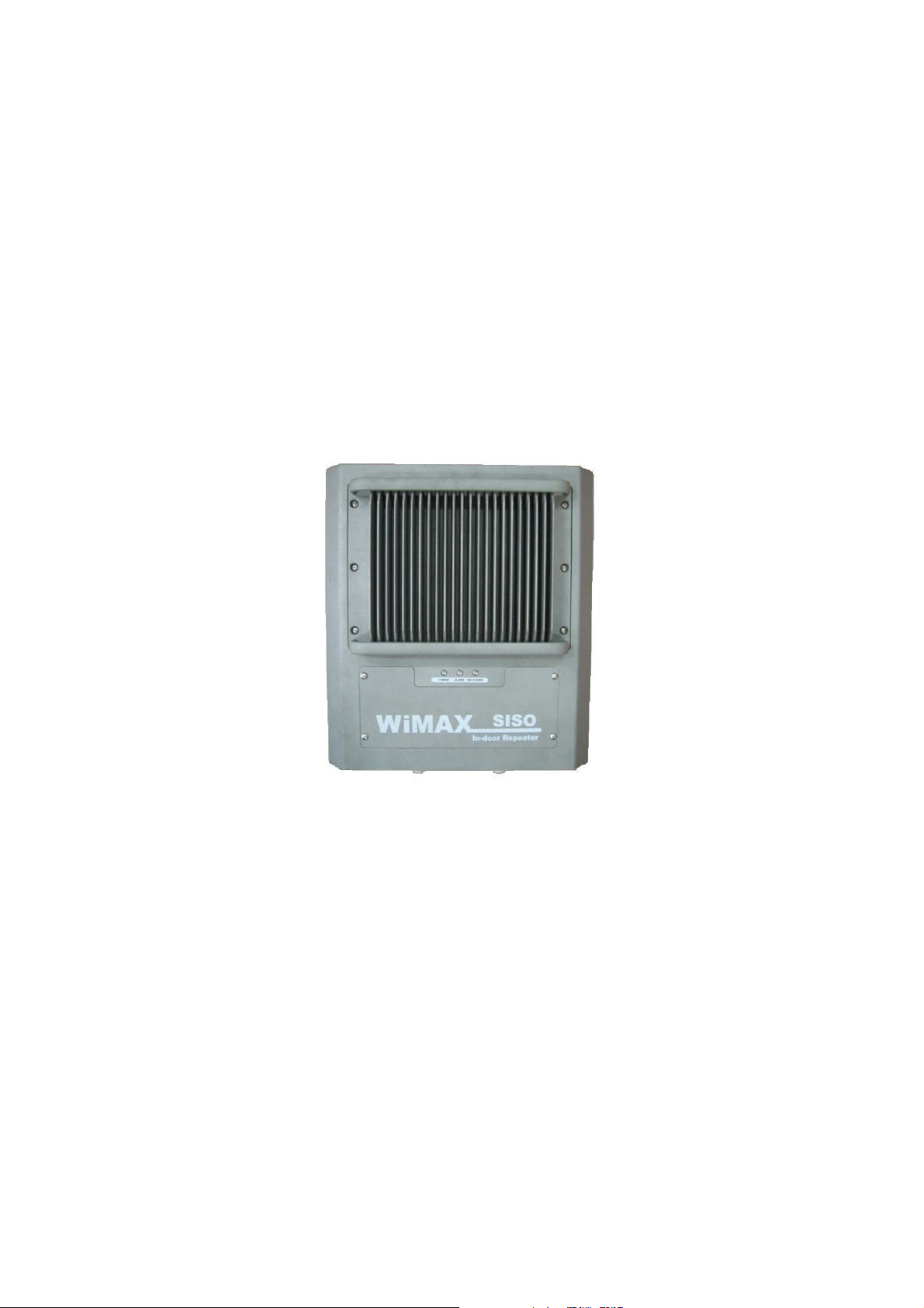
RSN-4GIR-24S
Description
R-tron, Inc.
Proprietary & Confidential Page 1
Issue: 1.0
Page 2

System Description RSN-4GIR-24S
Any changes or modifications to the equipment not expressly approved by the party
responsible for compliance could void user’s authority to operate the equipment.
Note : This unit was tested with shielded cables on the peripheral devices.
Shielded cables must be used with the unit to insure compliance.
CAUTION
This equipment is indoor use and all the communication
Proprietary & Confidential Page 2
Issue: 1.0
Page 3

System Description RSN-4GIR-24S
Abbreviations
Abbreviations used in this manual, in RSN-4GIR-24S.
AC Alternating Current
ANT Antenna
WiMAX Worldwide Interoperability for Microwave Access
SISO Single Input Single Output
DC Direct Current
GND Ground
GUI Graphic User Interface
LED Light Emitting Diode
PSU Power Supply Unit
MCU Main Control Unit
NCU Network Control Unit
UDC Up Down Converter
DFM Digital Filter Module
HPA High Power Amplifier
RF Radio Frequency
TEMP Temperature
VSWR Voltage Standing Wave Ratio
Proprietary & Confidential Page 3
Issue: 1.0
Page 4

System Description RSN-4GIR-24S
1. Introduction
RSN-4GIR-24S repeater is used to fill out areas in Mobile WiMAX systems, such as base
station fringe areas, business and industrial buildings, etc.
RSN-4GIR-24S receives signals from a base station, amplifies and retransmits the signals to
mobile stations. Also it receives, amplifies and retransmits signals in the opposite direction. Both
directions are served simultaneously with the following features:
188MHz bandwidth service
Band Selection (Continuous 30MHz) service
Roll Offs: 40 dBc at 1 MHz /80 dBc at 3.5 MHz outside pass-band
The RSN-4GIR-24S Repeaters are controlled by powerful microprocessors. Operational status
LEDs are visible on the front of the repeater.
The repeater works with convection cooling without fan because it has a radiator behind the
body of RSN-4GIR-24S.
Operational parameters, such as gain, power levels, alarm condition, Automatic Gain Control
condition, etc. are set using a desktop or notebook and the Local GUI or WEB GUI, which
communicate, either locally or remotely via the UTP(Unshielded Twisted Pair Wire) cable, with
the repeater.
Proprietary & Confidential Page 4
Issue: 1.0
Page 5

System Description RSN-4GIR-24S
2. Description
2.1 System Specifications
2.1.1 Electrical Specifications
Parameter Down Link Up Link
Operating Frequency 2502MHz~2690MHz 2502MHz~2690MHz
Freq. plan
Gain 50dB to 80dB
Max output power 24dBm
Roll off
Gain ripple ±1.5dB
Delay 5.0uS Max
VSWR 1.5Max
Input Range -26dBm ~ -56dBm
Power supply 110V~240V, 50/60Hz typ.
Operating temperature -10℃~50℃
Consumption power ≤130W
AB/BC/CD/EF/FH/HG (*reference)
≤40dBc @Fedge+/-1MHz
≤80dBc @Fedge+/-3.5MHz
Band Selection Continuous 33MHz
-13dBm @ ± 16.5MHz from 3FA Center
-13dBm @ ± 18.5MHz from 3FA Center
ACP
-37dBm @ ± 20MHz from 3FA Center
-37dBm @ ± 23MHz from 3FA Center
*reference : Freq. Plan
AB : 2502~2535MHz
BC : 2518.5~2551.5MHz
CD : 2535~2568MHz
EF : 2624~2657MHz
FH : 2640.5~2673.5MHz
HG : 2673.5~2690MHz
Proprietary & Confidential Page 5
Issue: 1.0
Page 6

System Description RSN-4GIR-24S
2.1.2 Mechanical Specifications
Parameter Specification
RF connectors N-female x 2, SMA-female x 3
Size
14 X15.55 X 8.21(Inch),
355 X 395 X 208.5(mm)
Weight 44.24(lbs) ,20.04(kg)
Proprietary & Confidential Page 6
Issue: 1.0
Page 7

System Description RSN-4GIR-24S
2.2 Sub Unit Overview
RSN-4GIR-24S is composed of the following sub units:
UDC(Up Down Converter)
HPA(High Power Amplifier)
BPF(Band Pass Filter)
MCU (Main Control Unit)
NCU (Network Control Unit)
PSU (Power Supply Unit)
DFM (Digital Filter Module)
SWU (Switch Unit)
PSU
NCU
DFM
EMI
Filter
EMI Filter
MCU
UDC
SWU
HPA
BPF
Proprietary & Confidential Page 7
Issue: 1.0
Page 8

System Description RSN-4GIR-24S
2.2.1 Block diagram
The following, Figure explains how the RSN-4GIR-24S serves signals.
Proprietary & Confidential Page 8
Issue: 1.0
Page 9

System Description RSN-4GIR-24S
2.2.2 UDC Module
The UDC Module is basically a bi-directional amplifier that sharply filters out
unwanted noise.
<UDC Module>
2.2.3 BPF
BPF is the module which passes the frequency in BRS BAND. One BPF performs
simultaneously DL INPUT, UP OUPUT functions.
2.2.4 Main Control Unit (MCU)
MCU is the control unit of RSN-4GIR-24S. It controls and monitors operational
Proprietary & Confidential Page 9
Issue: 1.0
Page 10

System Description RSN-4GIR-24S
parameters. It also generates alarms, an event log and many other functions of the
RSN-4GIR-24S.
*Pin Map*
Port Connected to
J11 NCU
J12 SWU
J13 Main Power(5.5V)
J3 RFU1 Control pin 1
J4 RFU1 Control pin 2
J5 HPA Control pin
J6 PSU Control pin
J7 Sync Unit Control pin
J8 Local GUI
J9 LED
Proprietary & Confidential Page 10
Issue: 1.0
Page 11

System Description RSN-4GIR-24S
2.2.5 Network Control Unit (NCU)
NCU is the unit that controls the device using Ethernet based WEB GUI Connection
2.2.6 Power Supply
The Power Supply Unit (PSU) supplies a steady DC power to RSN-4GIR-24S by drawing
power from the general in-wall AC outlets
*Specification*
Proprietary & Confidential Page 11
Issue: 1.0
Page 12

System Description RSN-4GIR-24S
Item Specifications
Environmental
Voltage AC110~240V
Rated Output(DC)
Frequency 60Hz typ.
Leakage Current 0.5mA max.@110V AC
2.2.7 High Power Amplifier (HPA)
The High Power Amplifier the transmitted signal from a base station at the final
stage of the repeater and vice versa.
Operating Temp
-10℃ ~ 50℃
Humidity 20%~90%RH
Cooling method Natural air
7VDC, 3A / -28VDC, 5.5A /
28VDC, 5.5A / 12VDC, 5.5A
/ -12VDC, 5.5A
<HPA>
Proprietary & Confidential Page 12
Issue: 1.0
Page 13

System Description RSN-4GIR-24S
2.2.8 Digital Filter Module (DFM)
<DFM>
Proprietary & Confidential Page 13
Issue: 1.0
Page 14

System Description RSN-4GIR-24S
2.2.9 Switch Unit
2.2.10 Noise (EMI) Filter
2.2.11 LED Board
<Front Side> <Rear Side>
Proprietary & Confidential Page 14
Issue: 1.0
Page 15

System Description RSN-4GIR-24S
2.2.12. Communication Board
<Front Side> <Rear Side>
Proprietary & Confidential Page 15
Issue: 1.0
 Loading...