

Page 1
iDEN Add-On Filter Box
User’s Manual
R-tron Inc.
User’s Manual -1-
Page 2

This document describes the specifications, installation and operation of iDEN Add-On Filter Box.
Hardware and software mentioned in this document are subject to continuous development and
improvement. Consequently, there may be minor discrepancies between the information in the
document and the performance and design of the product. Specifications, dimensions and other
statements mentioned in this document are subject to change without notice.
R-tron Inc. 6402 College Boulevard Overland Park, KS 66211
Phone: +1-913-344-9977, 1-888-31R-TRON Fax: +1-913-344-9988 Internet: www.r-tron.com
R-tron is registered trademarks of R-tron Inc. Other products and company names mentioned herein this
manual might be trade marks or trade names of their respective owners.
This document or parts of it may not be reproduced without the written permission of R-tron Inc.
Infringements will be prosecuted. All rights reserved
Copyright © R-tron Inc. 2000-2007
User’s Manual -2-
Page 3

iDEN Add-On Filter Box
Contents
Abbreviations .......................................................................................................................5
1. Introduction...........................................................................................................6
2. Description.......................................... ...................................................................8
2.1 System Specifications ....................................................................................................... 8
2.1.1. Electrical Specifications.......................................................................................... 8
2.1.2. Mechanical Specifications ...................................................................................... 8
2.2 Sub Unit Overview........................................................................................................... 10
2.2.1. Block Diagram .......................................................................................................11
2.2.2. Filter Module......................................................................................................... 12
2.2.3. Duplexer ............................................................................................................... 13
2.2.4. MCU (Main Control Unit) ...................................................................................... 14
2.2.5. Power Supply ....................................................................................................... 15
3. Hardware Installation............................................................................................16
3.1 Check List of Items.......................................................................................................... 16
3.2 Mounting.......................................................................................................................... 17
3.3 Grounding........................................................................................................................ 17
3.4 RF Cable Connection...................................................................................................... 18
3.5 Bandwidth & Band Setup ................................................................................................ 19
3.6 Power Up......................................................................................................................... 21
4. Troubleshooting....................................................................................................22
4.1 RF Connection Check ..................................................................................................... 22
4.2 Power Connection ........................................................................................................... 22
4.3 Red Light on the Alarm LED............................................................................................ 23
User’s Manual -3-
Page 4

iDEN Add-On Filter Box
Figures
Figure 1. R-tron iDEN Add-On Filter Box..................................................... ... ... ........................ 6
Figure 2. Overview: Interference Filtering........................................................... ... ................... 7
Figure 3. Dimension of iDEN Add-On Filter Box.........................................................................9
Figure 4. Internal View of iDEN Add-On Filter Box...................................................................10
Figure 5. Block Diagram ....................................................................................... ... .............. 11
Figure 6. Filter Module........................................................................................................... 12
Figure 7. Duplexer ............................................ .................................................................... 13
Figure 8. Main Control Unit................................................................................................ .... 14
Figure 9. Power Supply.............................. ... ........................................................ ... .............. 15
Figure 10. Items.................................................................................................................. 16
Figure 11. Mounting ................................................ ............................................................ 17
Figure 12. Grounding...........................................................................................................18
Figure 13. Configuration: RF Cable Connection...................................................................... 18
Figure 14. Dip Switches for Bandwidth and Band Setup ......................................................... 19
Figure 15. Index Table for Bandwidth and Band Setup........................................................... 19
Figure 16. Power Cord Connection........................................................................................ 21
Figure 17. LEDs Off ............................................................................................... .. ............ 22
Figure 18. AC power cord Check........................................................................................... 23
Figure 19. Red Light on Alarm LED ....................................................................................... 23
User’s Manual -4-
Page 5

iDEN Add-On Filter Box
Abbreviations
Abbreviations used in this manual, in iDEN Add-On Filter Box.
AC Alternating Current
ANT Antenna
CDMA Code Division Multiple Access
DC Direct Current
GND Grounding
GUI Graphic User Interface
iDEN Integrated Digital Enhanced Network
LED Light Emitting Diode
PSU Power Supply Unit
RF Radio Frequency
TEMP Temperature
VSWR Voltage Standing Wave Ratio
User’s Manual -5-
Page 6

iDEN Add-On Filter Box
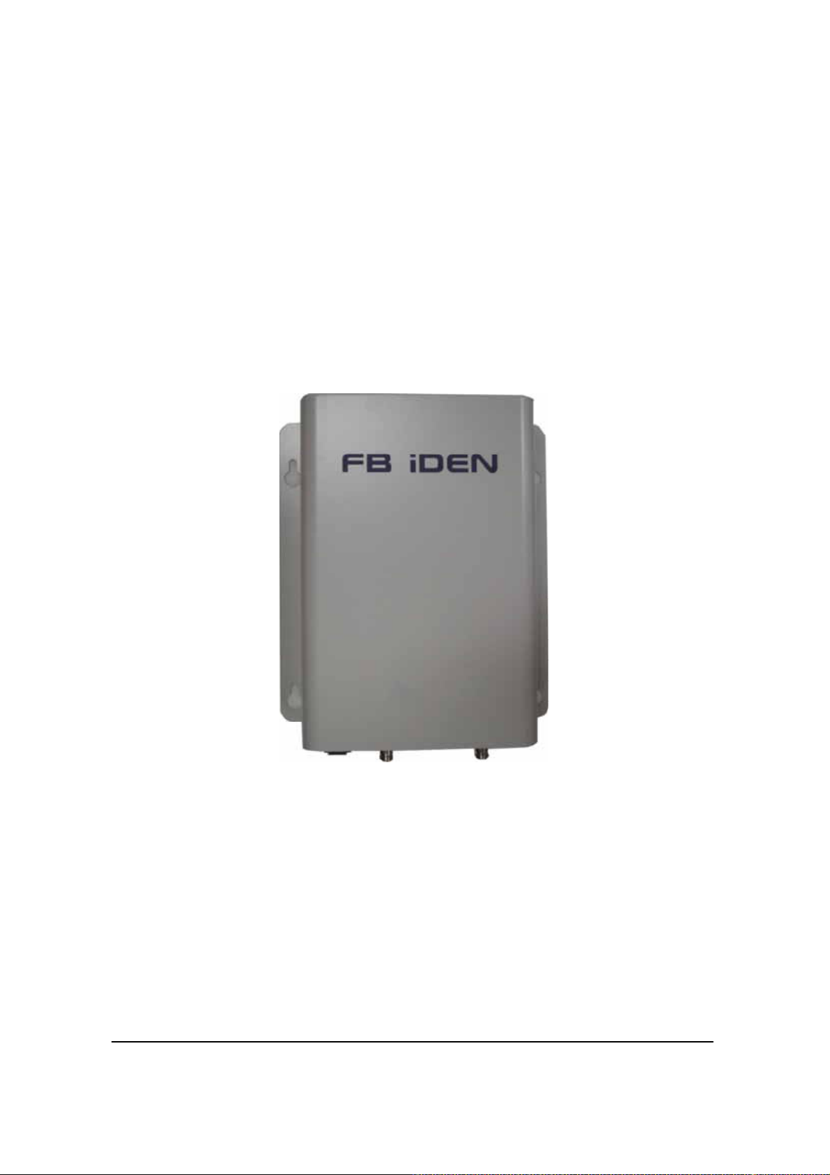
1. Introduction
Bandwidth &
Band Setup Table
Filtered
Output Port
AC Power Socket & Switch
Input Port
Dip Switch for Bandwidth & Band Setup
Screw for Grounding
Figure 1. R-tron iDEN Add-On Filter Box
The interference within the service frequency bands is a target to be
removed because it causes the degradation of the service quality and
shrinking of the coverage.
iDEN Add-On Filter Box is the equipment for filtering off such interference
adjacent to iDEN downlink frequencies allocated at 800MHz’s and 900MHz’s
with the following features:
7MHz or 18MHz filtering @ 800MHz’s
5MHz filtering @ 900MHz’s
Band Shifting @ 800MHz’s and 900MHz’s
Roll Offs: 65 dBc at 0.5 MHz outside pass-band
User’s Manual -6-
Page 7

iDEN Add-On Filter Box
e
.
Interferenc
Donor Antenna
Service
Antenna
Mobile
DonorService
Filtered
Output
iDEN Add- On Filter BoxRepeater
Input
Base Station
Figure 2. Overview: Interference Filtering
User’s Manual -7-
Page 8

iDEN Add-On Filter Box
2. Description
2.1 System Specifications
2.1.1. Electrical Specifications
Parameter iDEN 800 iDEN 900
DL
(BW)
Frequency
Selection
Roll off DL
Gain ripple ±1.5dB (Typical)
Gain
Delay
VSWR
Range
Power supply 85V~264V, 50/60Hz typ.
Operating temperature *-10℃ ~ 50℃
Storage temperature -20℃~ 60℃
Consumption power ≤20W
DL
UL In-band 18M In-band 5M
18MHz
7MHz
5MHz
DL 0±1.5dB
UL ~ -7.9 dB Max
DL 8.0uS Max
UL 1uS Max
DL 1.5Max
UL 1.5 Max
DL -10dBm Max -10dBm Max Input
UL By Pass By Pass
In-band BW:18M
In-band BW:7.0M
851~869MHz
850.8~868.8MHz
850.8~868.6MHz
862~869MHz
861.8~868.8MHz
861.6~868.6MHz
≤65dBc
@Fedge+/-
500KHz
In-band BW:5M Band Selection
935~940MHz
934.8~939.8MHz
934.6~939.6MHz
≤65dBc
@Fedge+/-500KHz
2.1.2. Mechanical Specifications
Parameter Specification
RF connectors N-female x 2, SMA-female x 2
Size 4.52 X14.96 X 12.2(Inch),
115 X 380 X 310(mm)
Weight 6.4kg (14.1lbs)
User’s Manual -8-
Page 9

iDEN Add-On Filter Box
I.T.E
31CY
E258109
MADE IN KOREA
ELECTRICAL RATING : 100-24 0V ~ , 50/60Hz, 1A
COMPLIES WITH PART 24, FCC RULES.
FCC REG. NO. : STESPAITR001
MODEL NO. : RSP-AIT-R001
MAKER : R-tron lnc.
SERIAL NO. / DATE :
800M BS
18MHz
7MHz
18B FS 1
851~869MHz
851~869MHz
850.8~868.8MHz
850.6~868.6MHz
7B FS 2
862~869MHz
862~869MHz
861.8~868.8MHz
861.6~868.6MHz
900M FS 3
935~940MHz
935~940MHz
934.8~939.8MHz
934.6~939.6MHz
BRACKET
800M BS
OUTPUT MON. INPUT MON.
Filtered
OUTPUT
AC IN
100-240V ~
DANGER
RISK OF ELECTRIC SHOCK
18B FS 1
7B FS 2
INPUT
900M FS 3
ALARM
Figure 3. Dimension of iDEN Add-On Filter Box
User’s Manual -9-
Page 10

iDEN Add-On Filter Box
2.2 Sub Unit Overview
iDEN Add-On Filter Box is composed of the following sub units:
Filter Module
Duplexer
Main Control Unit (MCU)
Power Supply Unit (PSU)
EMI Filter
MCU
Filter Module
Duplexer
PSU
Figure 4. Internal View of iDEN Add-On Filter Box
User’s Manual -10-
Page 11

iDEN Add-On Filter Box
2.2.1. Block Diagram
The following, Figure 5, explains how the unit filters signals.
SAW Filter with Programmable options
851~869 / 850.8~868.8 / 850.6~868.6 MHz
FB iDEN
with -65dBc@±500KHz
Donor
antenna
Filter
Filter
Filter
Filter
806~869MHz
896~940MHz
Filter
Filter
18MHz
7MHz
851~869MHz
806~824MHz
896~901MHz
935~940MHz
SAW Filter with Programmable options
851~869 / 850.8~868.8 / 850.6~868.6 MHz
with -65dBc@±500KHz
LO1
LO2
SAW Filter with Programmable options
935~940 / 934.8~939.8 / 934.6~939.6 MHz
with -65dBc@±500KHz
PLL
Figure 5. Block Diagram
Filter
Filter
Filter
Filter
Filter
Filter
iDEN
Repeater
Service
antenna
User’s Manual -11-
Page 12

iDEN Add-On Filter Box
2.2.2. Filter Module
The Filter Module is basically a complex band-pass filter that sharply filters
out unwanted noise.
Output Port
Input Port
Figure 6. Filter Module
User’s Manual -12-
Page 13

iDEN Add-On Filter Box
2.2.3. Duplexer
A duplexer is a device that combines two or more signals onto a common
channel or medium to increase its transmission efficiency.
800/900MHz
Input
Input CPL
-10dB
Output CPL
-10dB
800/900MHz
Output
900MHz Input
800MHz Input
800MHz Output
Figure 7. Duplexer
900MHz Output
User’s Manual -13-
Page 14

iDEN Add-On Filter Box
2.2.4. MCU (Main Control Unit)
MCU is the control unit of iDEN Add-On Filter Box. It controls and monitors
operational parameters. It also generates alarms, an event log and many
other functions of the iDEN Add-On Filter Box.
USB1A_J1
LED1
LED2
LED3
MOL3
Figure 8. Main Control Unit
Pin Map
Port Connected to
USB1A_J1 Local OMT
MOL1 MCU Vcc(+6V)
MOL2 iDEN 800 PLL,B/S,OUT DET
MOL3 iDEN 900 PLL,B/S,OUT DET
MOL4 Dip Switch Control
LED
MOL4
MOL1
MOL2
LED
LED1 Red light indicates MCU power “on”
LED2 Green light indicates 800 PLL Lock
LED3 Green light indicates 900 PLL Lock
User’s Manual -14-
Page 15

iDEN Add-On Filter Box
2.2.5. Power Supply
The Power Supply Unit (PSU) supplies a steady DC power to iDEN Add-On
Filter Box by drawing power from the general in-wall AC outlets
Specifications
Environmental
Figure 9. Power Supply
Item Specifications
Operating Temp -10 ~60 ℃℃
Storage Temp -20 ~70 ℃℃
Humidity 20%~90%RH
Cooling method Natural air
Voltage AC85~264V
Current 4.2A Max / 12Vdc
Frequency 47~440Hz max (50~60Hz typ)
Leakage Current 0.5mA max.@110V AC
User’s Manual -15-
 Loading...