

Page 1

User’s Manual
of
Advanced MINI 30
Page 2

RSP-APE-030M
User’s Manual
R-tron., Inc. 2/15 page
Contents
1. Overview ------------------------------------------------------------------------ 3
2. Specifications
---------------------------------------------------------------- 4
2.1 System specifications ------------------------------------------------------- 4
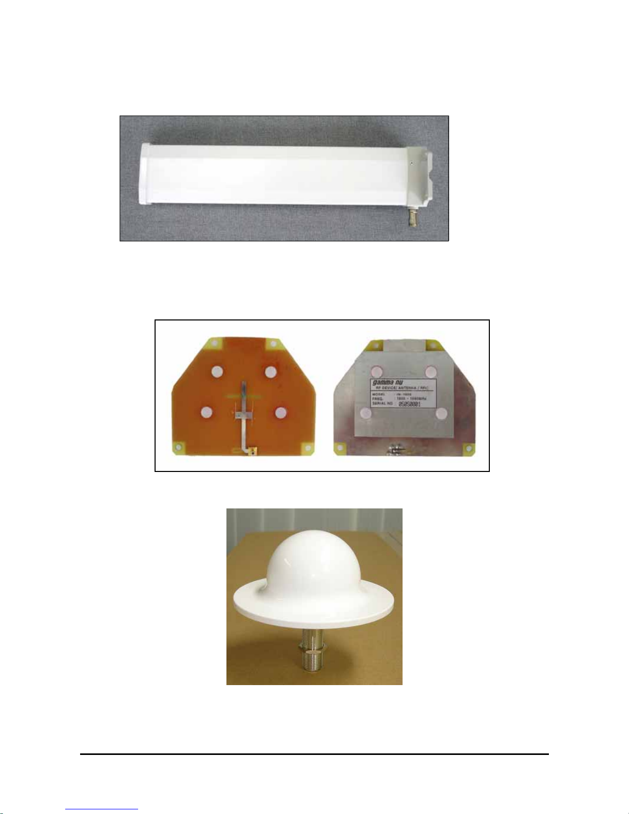
2.2 Antenna specifications ------------------------------------------------------ 5
2.3 Donor Antenna Diagrams -------------------------------------------------- 6
2.4 Distributor Antenna Diagrams -------------------------------------------- 6
3. System Configuration ---------------------------------------------------- 7
3.1 Block Diagram -----------------------------------------------------------------7
4. Installation ----------------------------------------------------------------------8
4.1 Installation Overview --------------------------------------------------------8
4.2 Safety ------------------------------------------------------------------------8
4.3 Installation information-1 ---------------------------------------------------9
4.4 Installation information-2 ---------------------------------------------------9
5. Graphic User Interface (for maintenance) ------------------- 10
5.1 GUI Overview --------------------------------------------------------------- 10
5.2 Preliminary steps for GUI Execution & Maintenance ------------- 11
5.3 How to operate GUI & Functions -------------------------------------- 12
Page 3
RSP-APE-030M
User’s Manual
R-tron., Inc. 3/15 page
1. Overview
Figure 1.1 RSP-APE-030M Repeater
R-tron RSP-APE-030M Repeater can be used in CDMA service hole spots like in-buildings,
underground and tunnels to cover its service area. This repeater system designed for dual and
simultaneous service, namely, it receives signals from the base station through donor antenna,
amplifies the signals and re-transmits it to one or other mobile terminals. Also, it amplifies the signals
which comes from mobile terminals through distributor antenna and re-amplifies it to base station.
Using local OMT(Operation and Maintenance Terminal) which is connected between repeater
control board and personal or laptop computer, it is possible to check or to control repeater status.
Page 4
RSP-APE-030M
User’s Manual
R-tron., Inc. 4/15 page
2. Specifications
2.1 System specifications
Parameter Specifications Remark
Down Link 1930 ~ 1995 MHz
Frequency Band
Up Link 1850 ~ 1915 MHz
65MHz Bandwidth
Down Link Maximum
Transmit Power
Up Link
+15 dBm Max. 7 channels
Operating Bandwidth 5 or 10 or 15 MHz
Gain 70dB
Gain Adjustment Range 30dB in steps of 1dB 1 dB Step
±885 kHz < -45 dBc
±1.98 MHz < -50 dBc
RBW = 30 kHz
Spurious
Emissions
± 2.25 MHz < -13 dBm RBW = 1 MHz
Ripple < 3.5dB
Freq. Selectivity -40dB ≤ 16.0MHz
Delay
< 5
㎲
Within operating bandwidth
VSWR ≤ 1.5
Waveform Quality Factor > 0.912
Noise Figure
≤ 5.0dB
Table 2.1 Repeater Specification
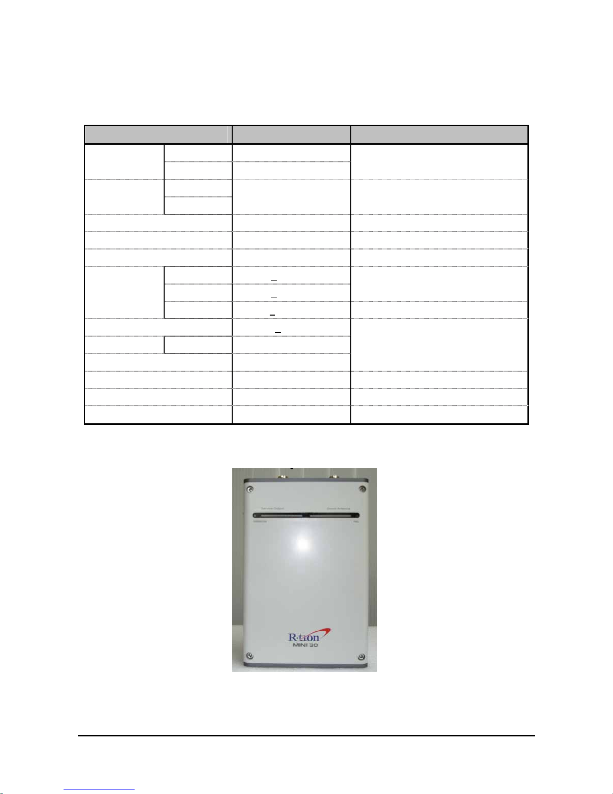
Figure 2.1 A body of the RSP-APE-030M
Page 5
Page 6
RSP-APE-030M
User’s Manual
R-tron., Inc. 6/15 page
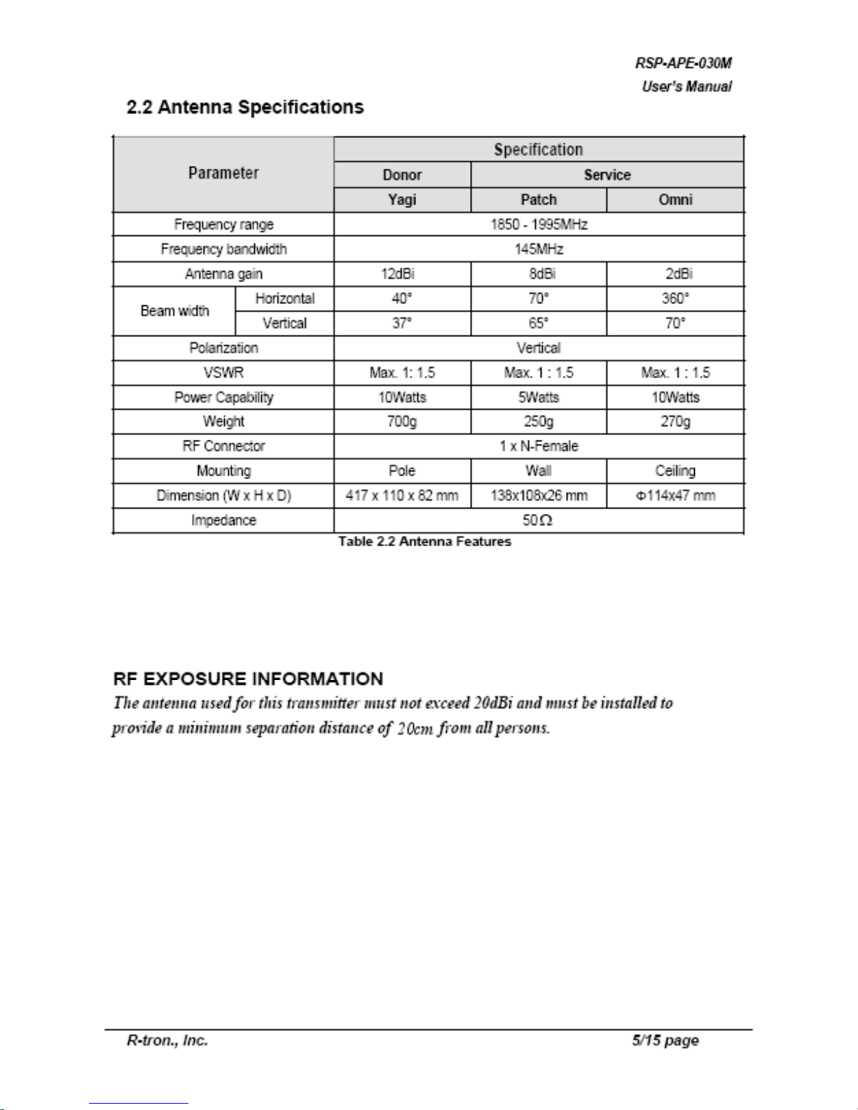
2.3 Donor Antenna Diagrams
Figure 2.2 Donor Antenna
2.4 Distributor Antenna Diagrams
Figure 2.3 Patch Antenna
Figure 2.4 Omni Antenna
Page 7

RSP-APE-030M
User’s Manual
R-tron., Inc. 7/15 page
3. System Configuration
3.1 Block Diagram
Figure 3.1 shows the block diagram of a band Selective repeater.
This diagram is applicable to repeaters for CDMA systems.
3.1.1 Downlink signal path
DL signal path gives a wireless mobile terminal path after receiving signal from base station,
amplifying and noise filtering. Please refer to the following picture 3.1, RSP-APE-030M repeater block
diagram.
3.1.2 Uplink signal path
UL signal path gives a path after receiving signal from mobile terminal, amplifying and noise filtering.
Please refer to the following picture 3.1, RSP-APE-030M repeater block diagram.
Page 8

RSP-APE-030M
User’s Manual
R-tron., Inc. 8/15 page
4. Installation
4.1 Installation Overview
The following gives you guide how you can install R-tron repeater properly, considering field
situation and installation specific conditions.
4.2 Safety
4.2.1 Purpose
The following information gives you how you can proceed your job correctly and eliminate
dangerous condition.
4.2.2 Application Range
Installation supervisor should check and do the proper thing to check preliminary dangerous
condition.
4.3 Installation information-1
4.3.1 Right-of-way
- The repeater shall be installed in the location owned or leased by the carrier.
- If the repeater is installed in the building, an appropriate space for the installation must be
considered.
4.3.2 Conditions for the Installation space
Repeater should be installed as followings :
In the building
- Avoid certain part which is located something heavy or water tank on the roof, considering
weight balance.
- Select certain place which is good for air ventilation.
- There will be enough space to check the repeater.
Page 9

RSP-APE-030M
User’s Manual
R-tron., Inc. 9/15 page
4.4 Installation Information-2
The installation of the repeater depends on the types of support, location, and the demand of
the carrier.
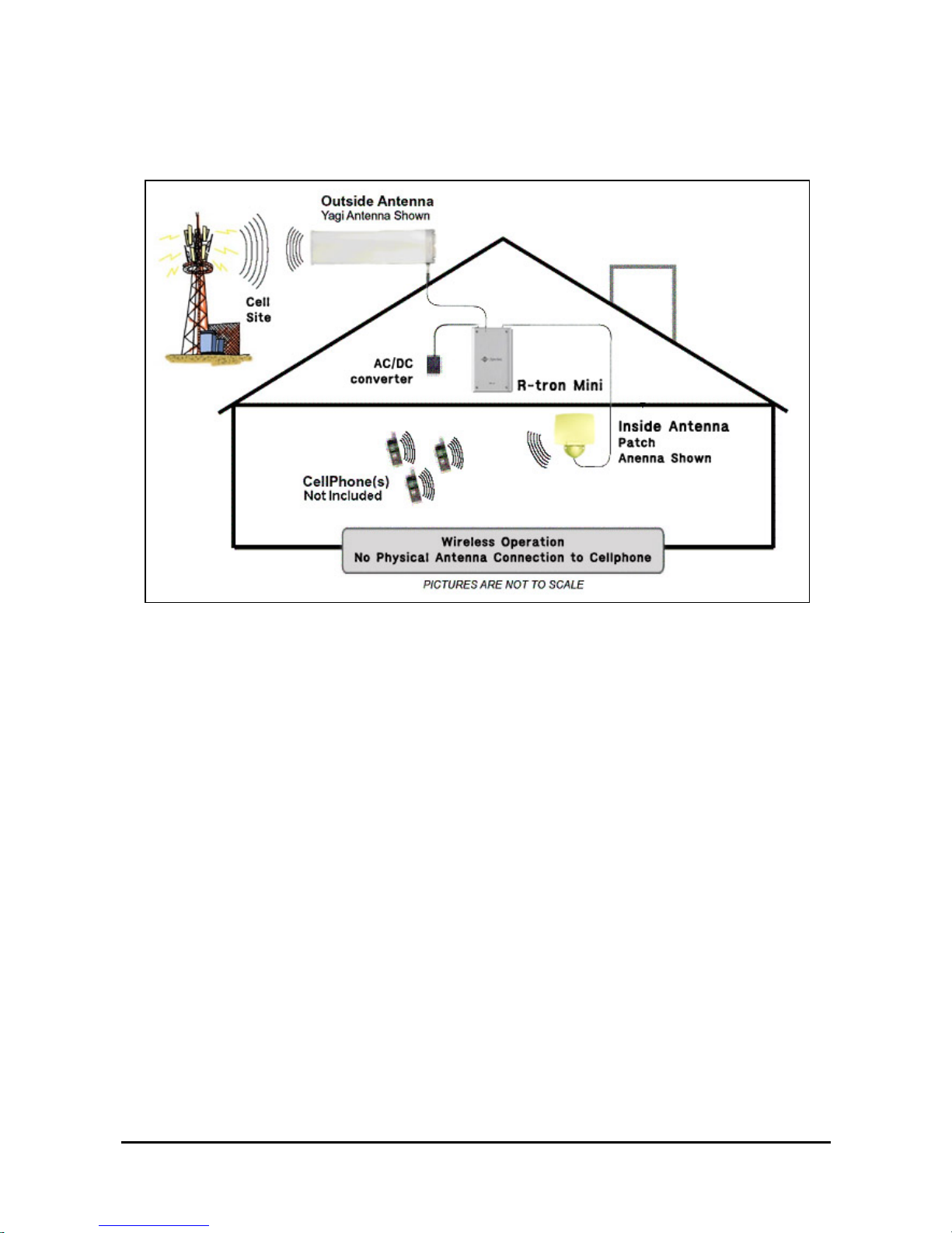
Figure 4.1 Antenna & Repeater Installation
4.4.1 General Condition
- Check whether the repeater status is correctly horizontal angle.
- Check whether there is enough space for maintenance and repair.
4.4.2 Installing Band set
- Repeater main box should be installed 8.2 inches at least, above from the ground.
- When you install the repeater main box, do not impact on its installation to other repeaters
maintenance.
- Safety plate should be installed 8.2 inches at least, above from the ground.
4.4.3 Precautions
- Never mount the donor or coverage antenna near a window, where Signal can easily pass through the
glass
- Mount the donor antenna as high as physically possible to the exterior of the building, maximizing
the vertical separation between antennas and pointing away from the building, toward the base station
site.
- Install the antennas taking advantage of any existing building structure Such as brick walls, metal
roofs, or multiple wall structures to additionally attenuate the path between them.
- When using directional antennas inside the building to cover Corridors and hallways, point the
interior antenna away from The donor antenna location .
- In extreme cases, the building configuration may not allow for Such separation and isolation. If
additional isolation is required, Coaxial attenuation may be inserted between the donor antenna and the
repeater , with the potential compromise to the coverage within the building
Page 10

RSP-APE-030M
User’s Manual
R-tron., Inc. 10/15 page
5. Graphic User Interface (for maintenance)
5.1. GUI Overview
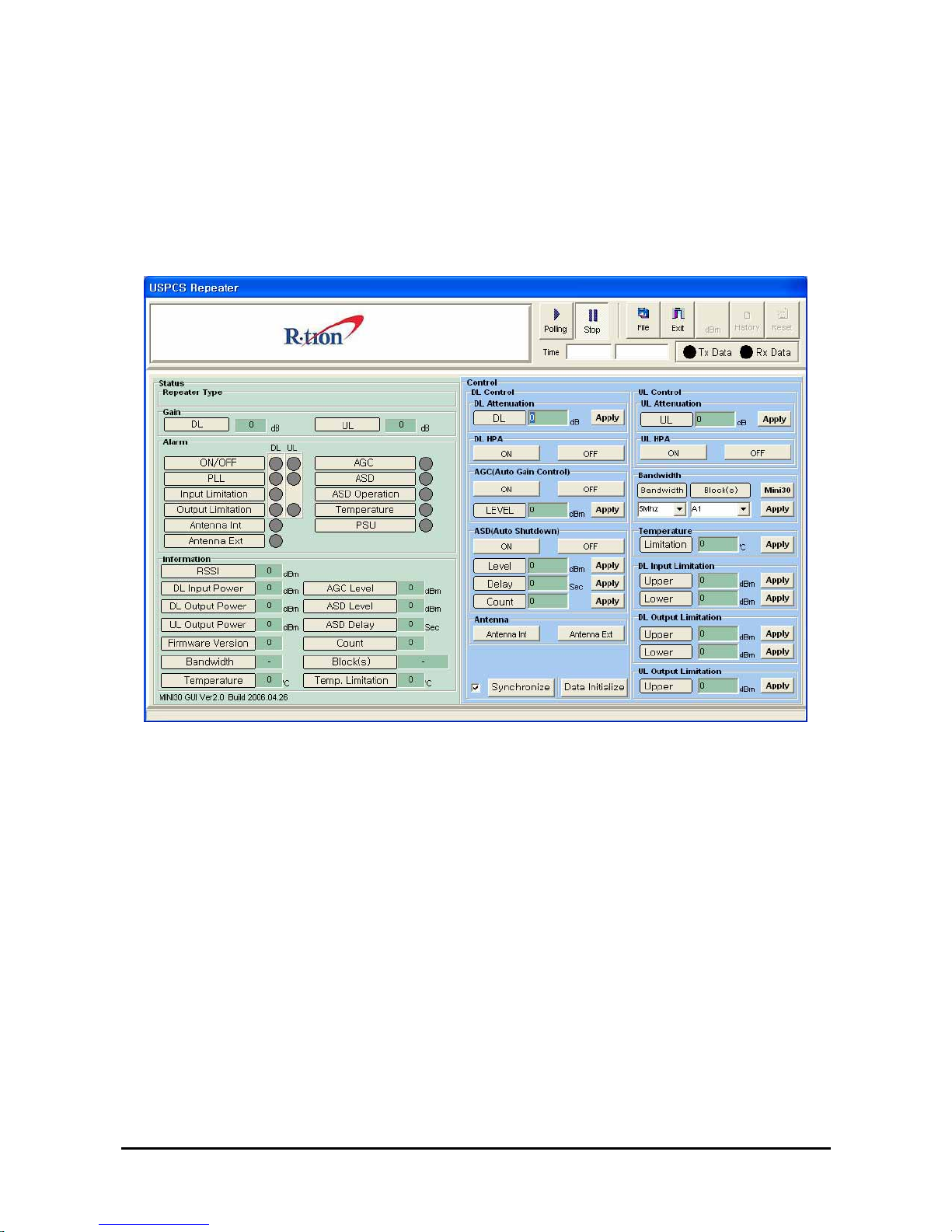
The following picture is RSP-APE-030M GUI Configuration.
Figure 5.1 Main window
When you first execute main window, you can see the above picture and it show you repeater status.
Page 11

RSP-APE-030M
User’s Manual
R-tron., Inc. 11/15 page
5.2 Preliminary Steps for GUI Execution & Maintenance
5.2.1 Preliminary Steps before using GUI
a. Check all connection status during the installation.
b. Set the baud rate which you are going to use.
c. Connect the repeater main power cable.
d. Connect RSP-APE-030M “LOCAL OMT” with PC, using RS232 cable.
Figure 5.2 Connection RSP-APE-030M with PC
5.2.2 Executing USB Driver & GUI program
a. Excuting “PreInstaller” and check the USB driver is normal and the port number.
Figure 5.3 USB Driver files
b. Excuting “MINI30_USPCS”
Figure 5.4 GUI files
5.2.3 GUI Communication
When the communication between Personal Computer and Repeater MCU board is OK, Tx/Rx yellow
LED which is up-left corner in the GUI screen will be flashed.
Figure 5.5 Communication Verification LED
Page 12
RSP-APE-030M
User’s Manual
R-tron., Inc. 12/15 page
5.3 How to operate GUI & Functions
Repeater can be controlled in Set-up mode. In Set-up pop-up window, you can input the value and
control DL/UL HPA, AGC, Shutdown and attenuation.
When you are going to check repeater status, click “Synchronize” button which is in the bottom side in
the screen. After setting output value, you can set AGC/ASD level value, using AGC/ASD button.
Figure 5.6 Setup mode
Page 13
RSP-APE-030M
User’s Manual
R-tron., Inc. 13/15 page
5.3.1 Description for icon indication
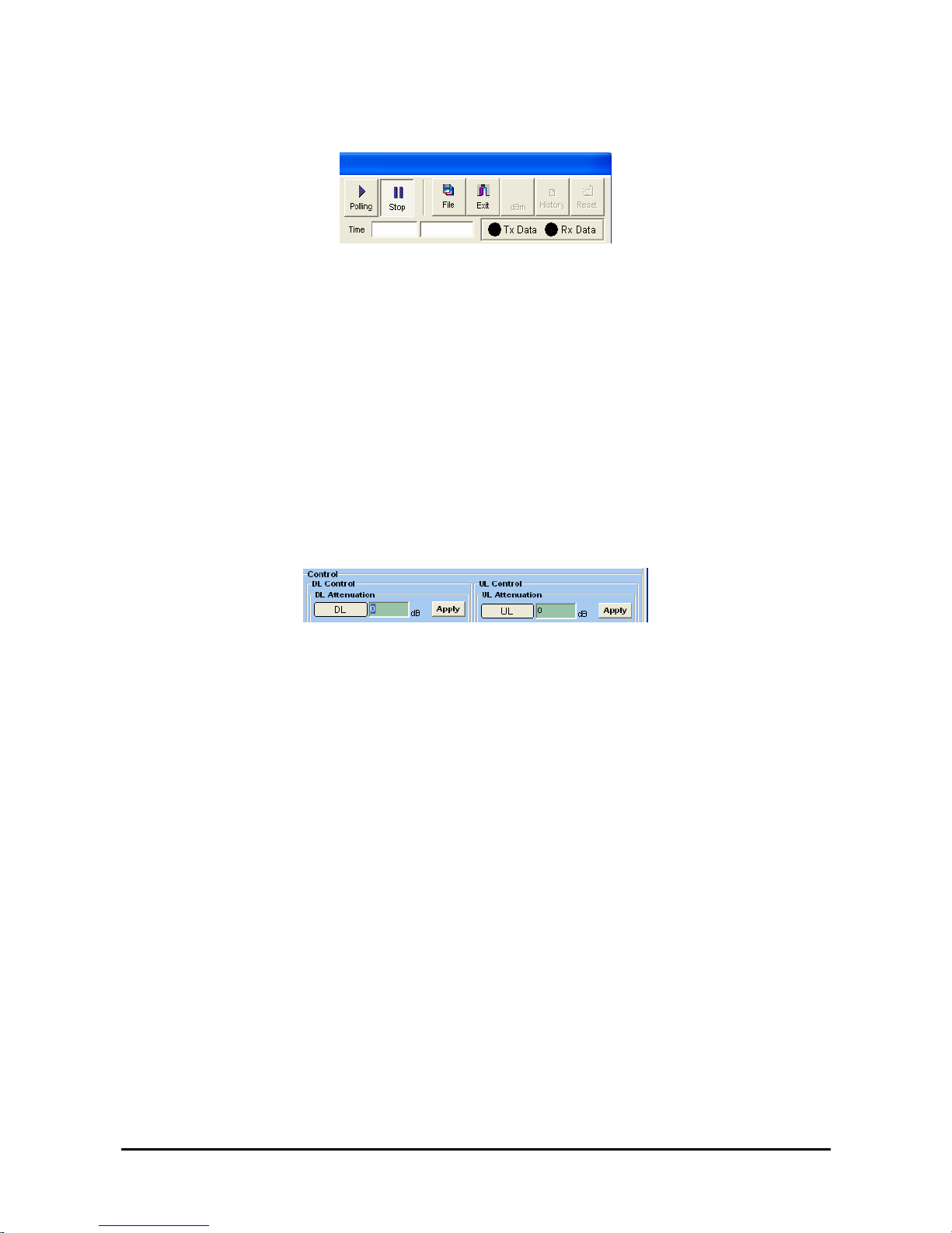
Figure 5.7 Main icons
▶ Polling : Communication possible
▶ Stop : Stop Communication
▶ File : Load the file of downloading
▶ Exit : Exit
5.3.2 How to set repeater gain
System gain value can be changed using Down/Up link attenuation value control which is in “ATTN”
pop-up window. Available set attenuation value is from 0 to 30 dB, Down/Up Link both.
You can check current system gain in status mode.
Figure 5.8 Gain Setting
Page 14

RSP-APE-030M
User’s Manual
R-tron., Inc. 14/15 page
5.3.3 Circumstance Condition Control
This function enables you to set the internal temperature of the system and the upper values of the
input/output level. To change the values, you can enter the desired settings and click the “APPLY”
button at the upper part of the control window.
In the left side, you can see current settings for the internal temperature of the system.
Figure 5.9 Control Window of Environmental Conditions
5.3.4 Controlling power amplifier
On the “ON/OFF” window, you can control power amplifiers for each path.
In the left side window, you can see the current path status (ON/OFF) of the system.
Figure 5.10 Control Window of Power Amplifier and Battery
5.3.5 Controlling input/output
You can set the upper/lower values of the current input/output RF power of the up-/down-links. To
change the values, you can enter the desired settings and click the “SET” button at the upper part of
the control window.
In the status mode, you can see the current input/output settings of the up-/down-links.
Figure 5.11 Controlling Input/output
5.3.6 AGC(Auto Gain Control) & ASD(Auto Shutdown) Setting
This function lets you control AGC settings and the ON/OFF status. To change a setting, you need to
enter a value and click the SET button at the lower part of the Control Window.
Page 15

RSP-APE-030M
User’s Manual
R-tron., Inc. 15/15 page
Figure 5.12 AGC/ASD Setting window
 Loading...