

Page 1

QUAD BAND OTA
(Verizon)
User’s Manual
Page 2

Notice
Trademark
R-tron is a registered trademark of R-tron Inc.
Other products and company names mentioned here in this manual might be trademarks or
trade names of their respective owners.
Copyright
Copyright © R-tron Inc. 2000-2010
All Rights Reserved
Any reproduction, distribution, or revisions of any or all portions of this manual is prohibited
without written permission from R-tron Inc.
Notice
This document describes the specifications, installation, and operation of the OTA repeater.
Hardware and software mentioned in this document are subject to continuous development
and improvement. Consequently, there may be minor discrepancies between the information
in the document, performance, and design of the product.
Specifications, dimensions, and other statements mentioned in this document are subject to
change without notice.
Questions or Comments
Address: R-tron America Inc. 6402 College Boulevard, Overland Park, KS 66211
Phone: +1-913-344-9977, 1-888-31R-TRON
Fax: +1-913-344-9988
E-mail: info@r-tronamerica.com
Website: www.rtronamerica.com
FCC Part 15.19
This device complies with part 15 of the FCC Rules. Operation is subject to The following
two conditions: (1) This device may not cause harmful interference, and (2) this device must
accept any interference received, including interference that may cause undesired operation.
FCC Part 15.21
Any changes or modifications (including the antennas) made to this device that are not
expressly approved by the manufacturer may void the user's authority to operate the
equipment.
RF Exposure Statement
FCC RF Radiation Exposure Statement: This equipment complies with FCC RF Radiation
exposure limits set forth for an uncontrolled environment. This device and its antenna must
not be co-located or operating in conjunction with any other antenna or transmitter.
Page 3
Safety Precautions
Opening the OTA equipment could result in electric shock and may cause severe injury.
Connect the equipment frame ground to the building ground.
Operating the OTA with antennas in very close proximity facing each other could lead to severe
damage to the repeater.
RF EXPOSURE INFORMATION
A minimum separation distance of 7.9 inches (20cm) must be maintained between the user
and the external antenna of the repeater to satisfy FCC RF exposure requirements. For more
information about RF exposure, please visit the FCC website at www.fcc.gov
This equipment is for indoor use only and enables the communication wiring to communicate
inside the building only.
Page 4

Contents
Glossary ............................................................................................................................... 2
1. Introduction ....................................................................................................................... 3
2. Description........................................................................................................................ 6
2.1. Main Unit
Overview...…………………………………………………………….………………………………….………
………..7
2.2. Internal
Configuration………………………………………………………….…………………………………………
………….8
2.2.1. Block
diagram……………………………………………………………….….………………………………………
…………..9
2.2.2. AC-DC
Adaptor……………………………………………………………………………………………………………
……..10
2.2.3. RFU(RF
Unit)……..…………………………………………………………………………………………………………
……..11
2.2.4. MCU(Main Control
Unit)………………………………………………………………….…………………………………12
2.2.5.
Duplexers…………………………………………………………………………………………………………
…………………13
3. Hardware Installation ...................................................................................................... 11
3.1. Check List of
Items………………………………………………………………………………………………………………
…..14
3.2.
Mounting……………………………………………………………………………………………………………
…………………….15
3.3.
Grounding…..……………………………………………………………………………………………………
……………………….17
Page 5

3.4. Cable
Connection…………………………………………………………………………………………………………
………….18
3.5. Power
On…………………………………………………………………………………………………………………
……………….18
4. Operation........................................................................................................................ 16
4.1. System
Requirements……………………………………………………………………………………………………
…………21
4.2. Network
Setup………………………………………………………………………………………………………………
…………21
4.2.1. Windows
XP…………………………………………………………………………………………………………………
…….21
4.2.2. Windows
2000………………………………………………………………………………………………………………
…..23
4.2.3. Windows
Vista………………………………………………………………………………………………………………
…..24
4.3. System Log
in……………………………………………………………………………………………………………………
…….27
4.4. System
Setup..……………………………………………………………………………………………………………
……………27
5. Troubleshooting .............................................................................................................. 41
6.
Specifications.................................................................................................................. 48
Appendix......................................................................................................................... 52
7.
Glossary
The following is a list of abbreviations and terms used in this manual.
Page 6
Abbreviation Definition
AC Alternating Current
ANT Antenna
ATT Attenuator / Attenuation
CDMA Code Division Multiple Access
DC Direct Current
DL Downlink
GND Grounding
GUI Graphic User Interface
LED Light Emitting Diode
PLL Phase-locked loop
PSU Power Supply Unit
RF Radio Frequency
RSSI Received Signal Strength Indication
TEMP Temperature
UL Uplink
VSWR Voltage Standing Wave Ratio
ALC (Automatic Level Control)
ALC feature prevents the repeater from exceeding its maximum output power by reducing the gain
automatically. ALC is used to adjust the gain to an appropriate level for a range of input signal levels.
ASD (Automatic Shutdown)
Automatic shut down protects the repeater from the oscillation or excessive input signal and
eliminates any degradation to the network.
There are three parameters: ASD Level, ASD Time, and ASD Iteration.
If the output power reaches higher than the “ASD LEVEL”, the repeater will shut down for “ASD
TIME” seconds and then it will turn the amp back on to measure the output power again. If this
repeats at “Iteration” times, the repeater will shut down permanently.
1. Introduction
QUAD BAND OTA is used to fill out areas in QUAD BAND systems, such as base station
fringe areas, business and industrial building, etc.
QUAD BAND OTA receives signals from a base station, amplifies and retransmits the signals
Page 7
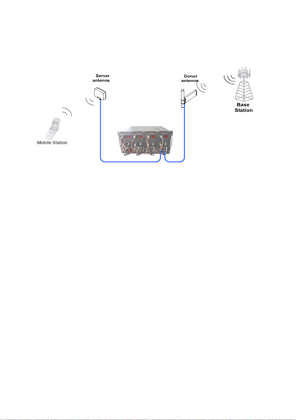
to the mobile stations. It also receives, amplifies and retransmits signals in the opposite
direction. Both directions are served simultaneously with the following features:
QUAD BAND OTA Key Features
◈ Composition(4 BDA by service band and combining Unit)
- 700MHz Band BDA for LTE Service
- Cellular Band BDA for EVDO/CDMA2000 Service (LTE Service is possible even the Firmware
update only)
- PCS Band BDA for EVDO/CDMA2000 Service
- AWS Band BDA for EVDO/CDMA2000 Service (LTE Service is possible even the Firmware
update only)
- Combining Unit (MUX) is for input and output signal of each BDA to a single antenna.
◈ Design(Each BDA is possible to service selected channels by the user within a band.)
- Possible to select any channel combination within a band caused by the Digital Filter.
- Using the Digital Filter: High quality, out of band rejection, high performance
◈ Possible to combine the BDA according to Band.
- Each BDA can be used as a stand alone unit(Use Privacy Ant Port)
- Possible to combine the BDA(Dual, Tri, Quad-band)
◈ User friendly design.
- Local monitoring and control through the Web GUI interface
- Remote monitoring and control through the Remote Access and Control
- Reports the status of connection as a function of SNMP regularly and reports an alarm if the
event occurred.
◈ Protection function
- Isolation and Oscillation Check
- Isolation cancellation Function
- Auto Gain Control
- Auto Shutdown
◈ Service Coverage
Page 8

- Possible to service by 25k square feet
- Use in office buildings, warehouses, underground parking lots, etc.
Page 9
2. Description
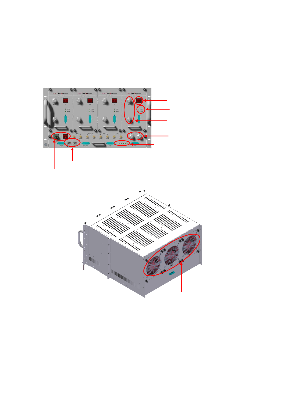
2.1 Main Unit Overview
700M Cellular PCS AWS
Local & Remote NMS
BDA Power Switch
BDA Status LED
BDA Donor & Server Ant Port
System Server & Donor Ant Port
System Status LED
AC Power & AC Power Switch
FAN Unit
Page 10
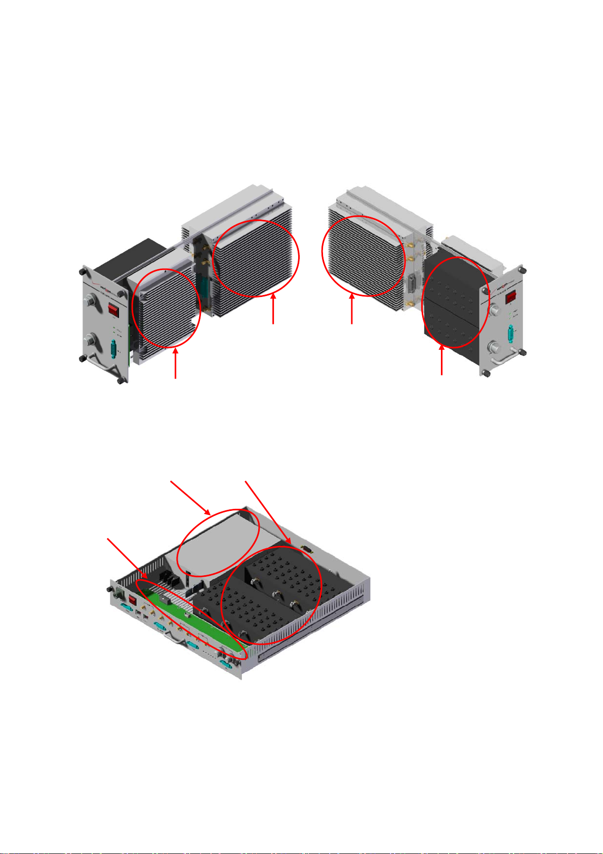
2.2 Internal Configuration
* BDA Unit
* MUX Unit
RFU
PSU
UL HPA
Multiplexer
(Donor and Server)
DL HPA
Duplexer
MCU
Page 11
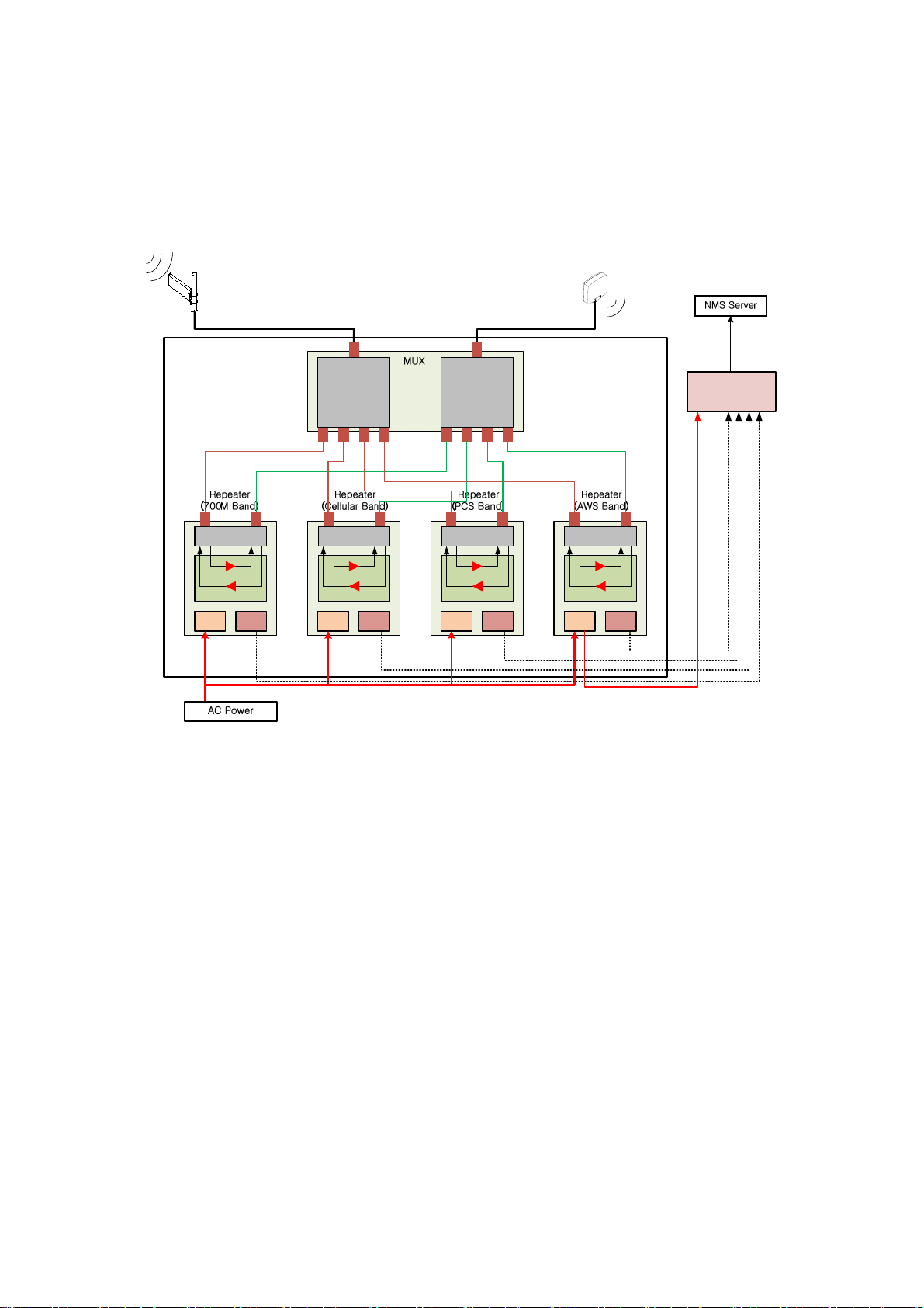
2.2.1 Block Diagram
The following diagram explains how the QUAD BAND OTA services signals.
Donor
antenna
Service
antenna
4-plexer 4-plexer
Duplexer
DL
UL
MCUPSU MCUPSU MCUPSU MCUPSU
Duplexer
DL
Duplexer
DL
UL
UL
Modem Box
Duplexer
DL
UL
Page 12
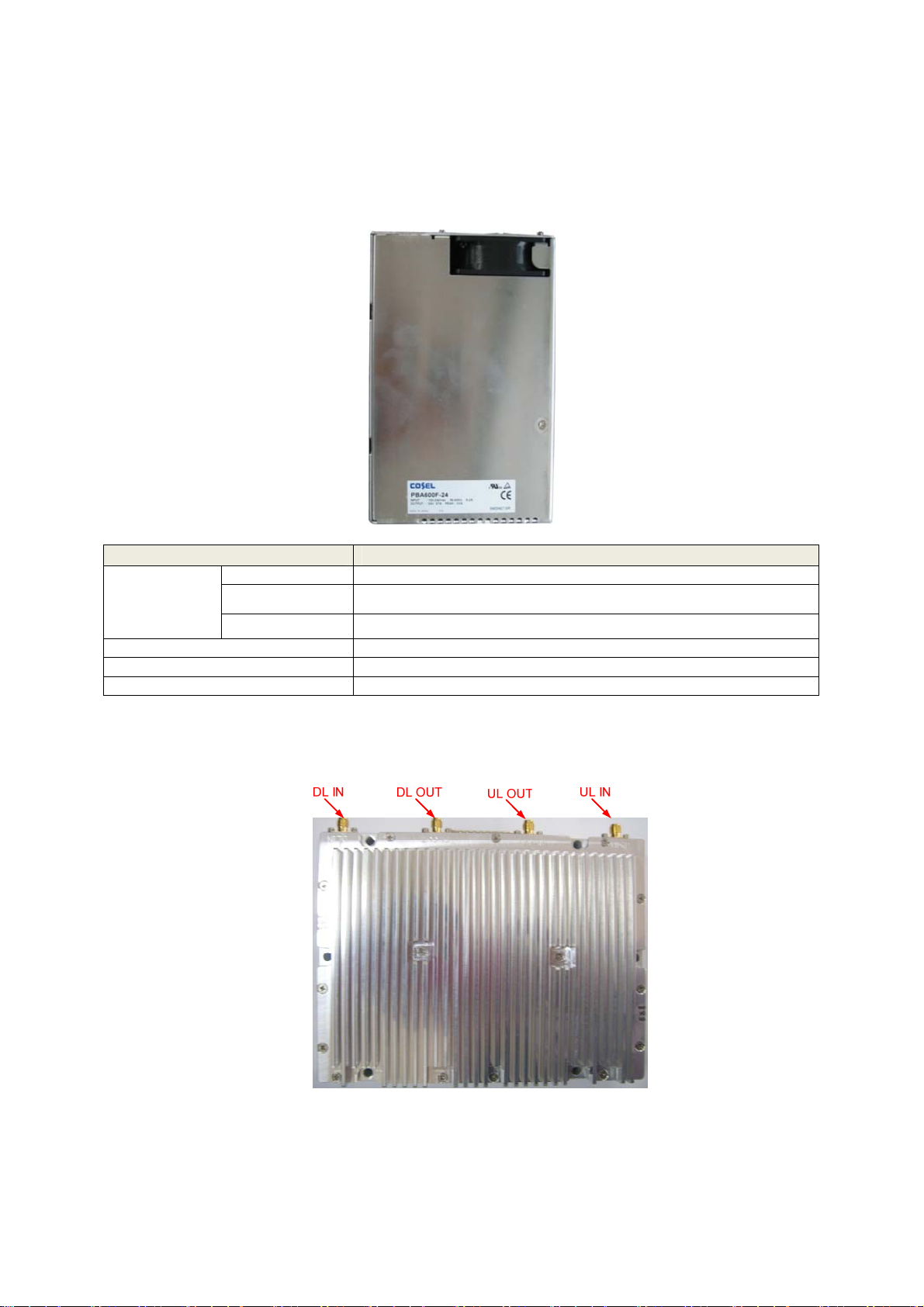
2.2.2 PSU
The AC-DC adaptor supplies a steady DC power to the CDMA MINI equipment by drawing power
from the general in-wall AC outlets.
Specification
Item Specification
-10˚C~50˚C (14˚F~122˚F)
AC 85-264V
+24V/27A (600W)
50/60(47-63)
Environmental
Frequency
Operating Temp
Humidity 20%~90%RH
Cooling method Convection.
Voltage
Current
2.2.3 RFU (RF Unit)
The RFU (RF Unit) is a bi-directional amplifier that sharply filters out unwanted noise.
Page 13
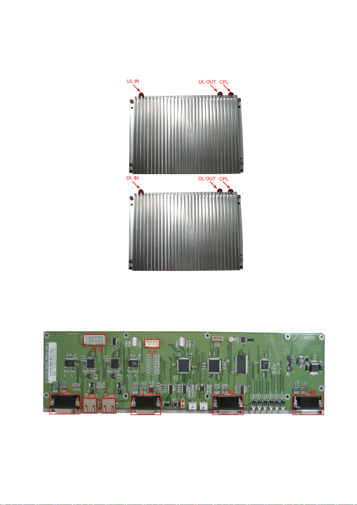
2.2.4 HPA (High Power Amplitude)
2.2.5 MCU (Main Control Unit)
The MCU (Main Control Unit) is the control unit of a QUAD BAND OTA. It controls and
monitors operational parameters. It is also responsible for generating alarms, keeping event
logs and performing many other functions of the QUAD BAND OTA.
Page 14
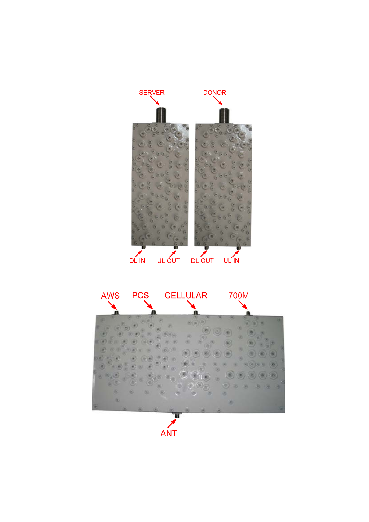
2.2.6 Duplexer
A duplexer is a device that combines two or more signals onto a common channel or medium
to increase its transmission efficiency.
2.2.7 Multiplexer
3. Hardware Installation
The installation procedure is as follows:
• Check List of Items
Page 15
• Mounting
• Grounding
• RF Cable Connection
• Power On
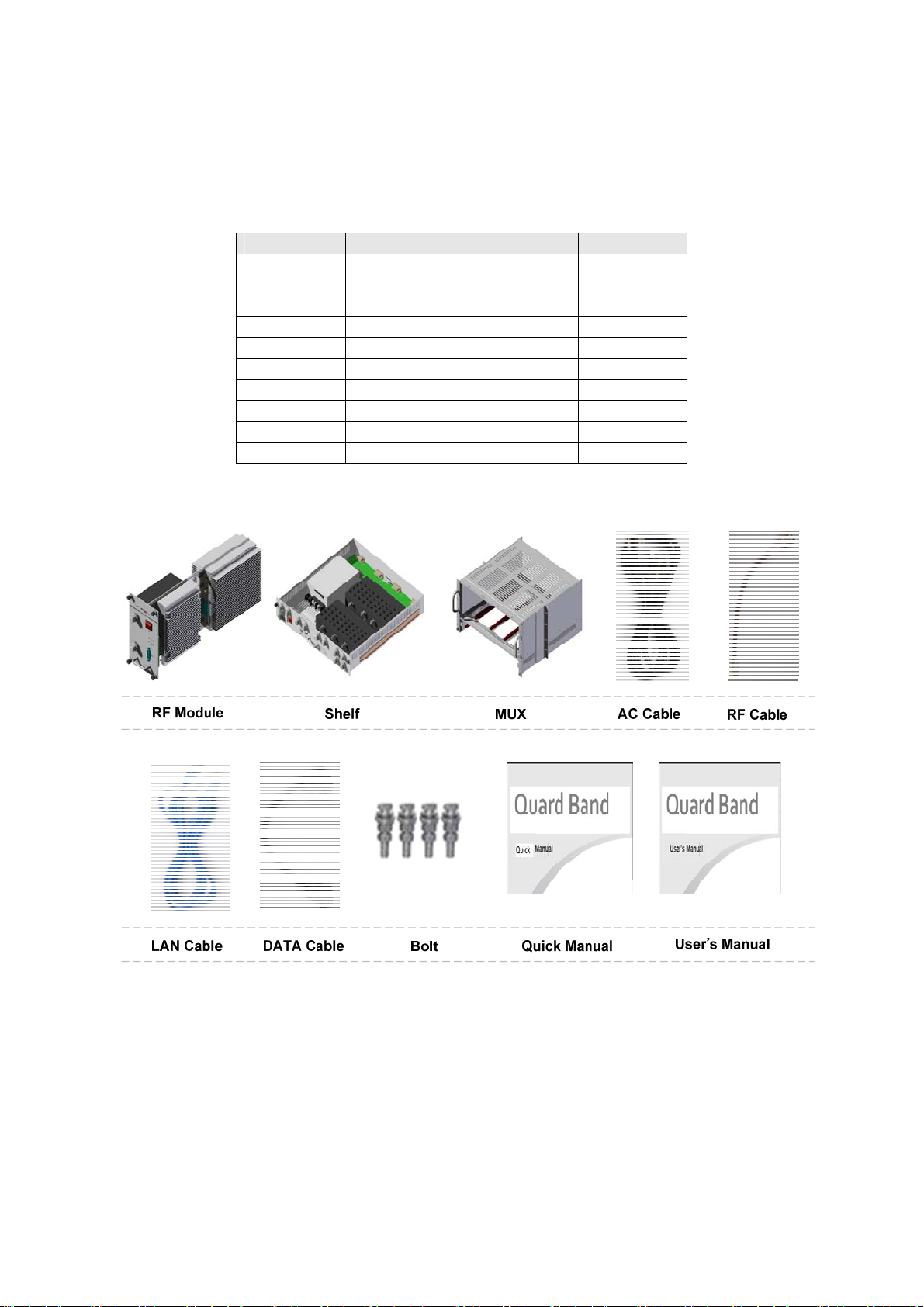
Index Items Quantity
Item Figure
1 RF Module 4
2 Shelf 1
3 MUX 1
4 AC Cable 1
5 RF Cable 8
6 LAN Cable 1
7 DATA Cable 4
8 Bolt 4
9 Quick Manual 1
10 User’s Manual 1
Page 16
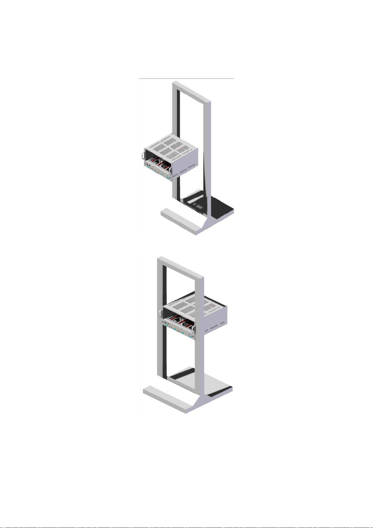
3.2 Mounting
Step 1 : Find a location for the Repeater to be installed on a 19 inch rack.
Step 2 : Insert the Repeater on the shelf.
Page 17
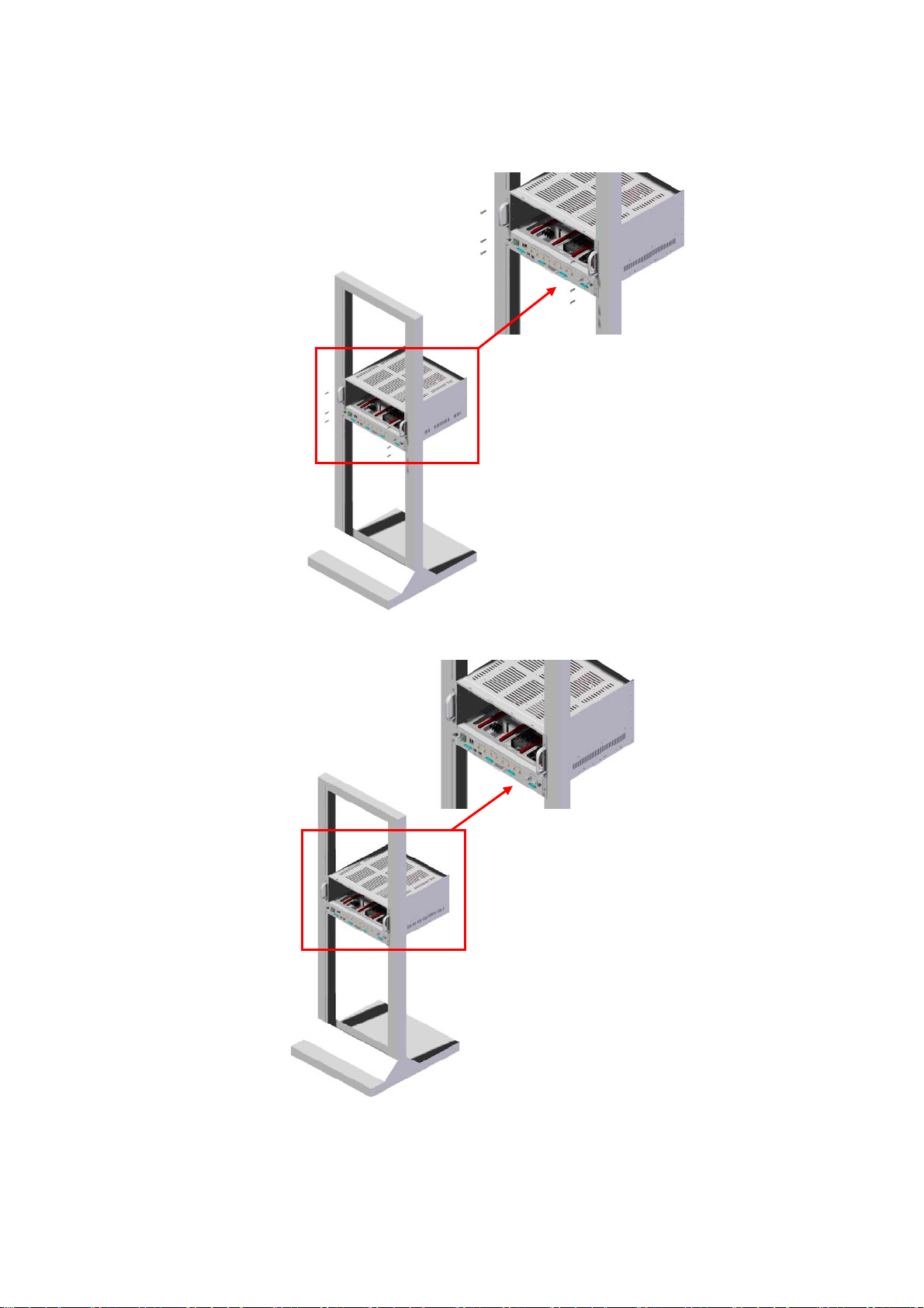
Step 3 : Fix the Repeater shelf using the provided screws.
Step 4 : Insert the Combine Unit(MUX) and Fix it.
Step 5 : Insert each BDA for the Repeater and secure it.
Page 18
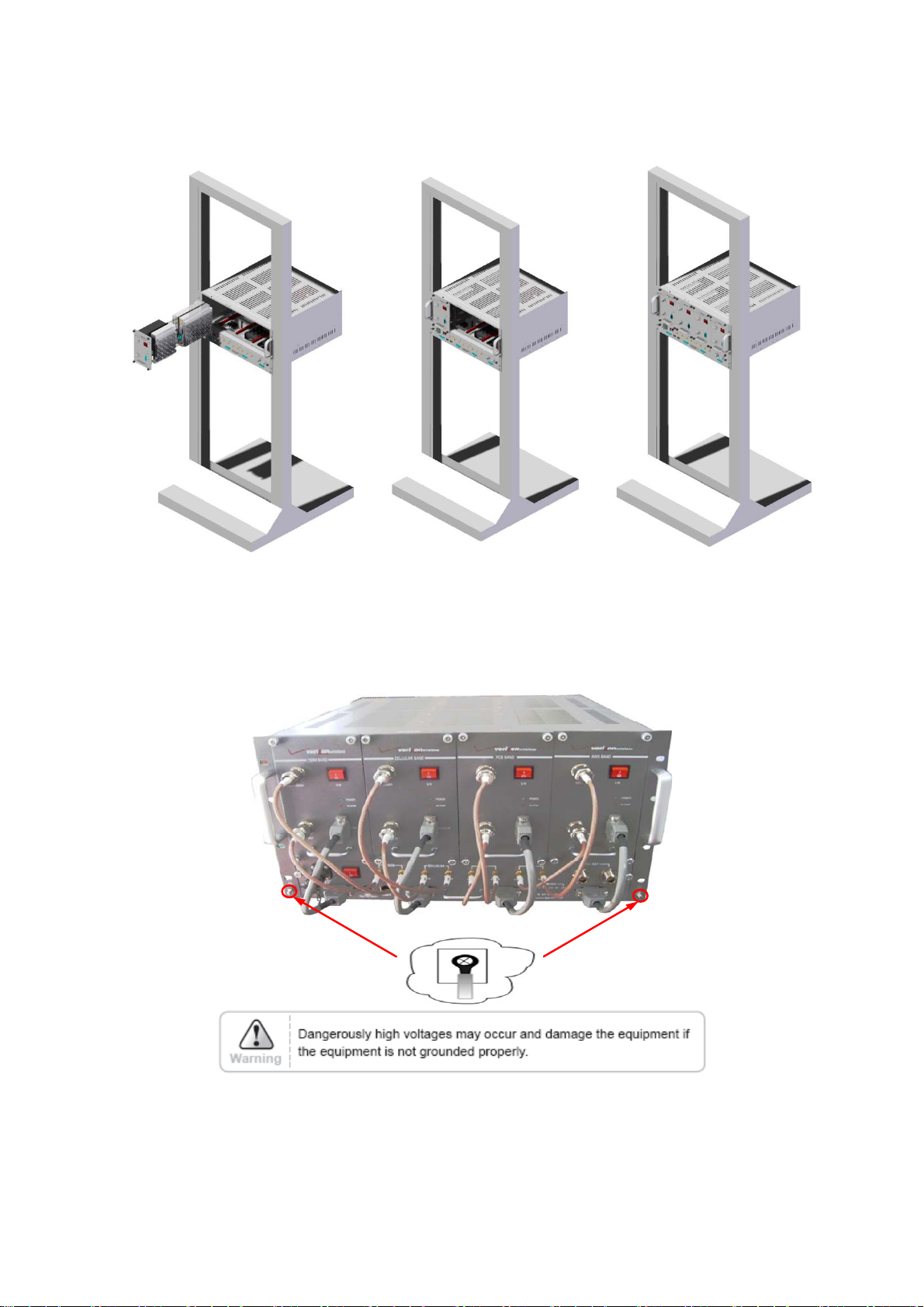
3.3 Grounding
A rod on the left side is intended for a building ground. Connect the ground cable to the rod.
Page 19

3.4 RF Cable Connection
Step 1 : Connect a cable from the donor antenna to the Donor Antenna Port.
Step 2 : Connect a cable from a repeater’s service antenna to the Server Antenna Port.
3.5 Power On
Step 1 : Connect the power cord.
Step 2 : Plug the power cord into a wall outlet.
Step 3 : Check if the green LED at the Top turns on.
4. Operation
Page 20

4.1 System Requirements
QUAD BAND OTA operates on a customer provided PC based platform with the following
system requirements:
• Windows® 2000, Windows® XP or Windows® Vista
• Internet Explorer 6.0(Recommended) or higher
• 128 MB RAM or higher
• Pentium Ⅲ processor or higher
• RJ-45 jack required
4.2 Network Setup
4.2.1 Windows XP
Step 1 : Click the Start button and select My Network Places.
Step 2 : Click View network connections.
Step 3 : Right-click Local Area Connection to see a shortcut menu and click Properties.
Page 21

Step 4 : Select Internet Protocol (TCP/IP) and click Properties.
Step 5 : Check Obtain an IP address automatically and click OK.
Step 6 : Close all windows.
Page 22

4.2.2 Windows 2000
Step 1 : Click the Start button, point to Settings, and then click Network and Dial-up
Connections.
Step 2 : Right-click Local Area Connection to see the shortcut menu and click Properties.
Step 3 : Select Internet Protocol (TCP/IP) and click Properties.
Step 4 : Check Obtain an IP address automatically and click OK.
Page 23

Step 5 : Close all windows.
4.2.3 Windows Vista
Step 1 : Click the Start button and select Control Panel.
Step 2 : Click Network and Internet.
Step 3 : Click Network and Sharing Center.
Page 24

Step 4 : Click View status of Local Area Connection.
Step 5 : Click Properties and a caution pop-up window will appear. Click OK.
Step 6 : Select Internet Protocol Version 4 (TCP/IPv4) and click Properties.
Page 25

Step 7 : Check Obtain an IP address automatically and click OK.
Step 8 : Close all windows.
Page 26

4.3 System Login
Open your Web browser and type “192.168.0.1” into the URL address box.
Then press the Enter key.
4.4 System Setup
4.4.1 Clock
The clock will automatically be set to your PC time when you click the APPLY
4.4.2 Network
When you click on the Network, the Web GUI screen is automatically updated every 5
seconds.
Page 27

4.4.3 Control
Quad OTA Repeater does not need to be logged-In. The user can control the repeater
directly with the WEB GUI.
Case1. 700M BAND
Band Select
Solution 1. Manual Gain Setting
Step 1A Select the repeater.
Step 2A Select the channel band of the area in use.
Page 28

Step 3A Turn off the DL and UL Amplifier
Step 4A ALC must be turned off
(700M, PCS, AWS : 30dBm / CELLUAR : 25dBm)
Step 5A The Setup is the Available Maximum Gain which defines as the maximum
gain. Change the DL and UL Gain. Turn on the DL and UL Amplifier
Result 1 DL and UL gain are fixed and the output power depends on the input power
Result 2 Constant Maximum DL Output Power 30dBm
If the DL Input Power >= -57dBm
Page 29

Solution2 . ALC Gain Setting.
Step 1A ~ Step 3A
Step 4B ALC must be turned on.
(700M, PCS, AWS : 30dBm / CELLUAR : 25dBm)
Page 30

Step 5B Setup is the Available Maximum Gain which is defined as the maximum
gain. Change the DL and UL Gain. Turn on the DL and UL Amplifier
Page 31

Case2. CELLULAR BAND
Solution 1. Manual Gain Setting Gain
Step 1A Select the repeater.
Step 2A Select the channel band of the area in use.
Page 32

Step 3A Turn off the DL and UL Amplifier
Step 4A ALC must be turned off
(700M, PCS, AWS : 30dBm / CELLUAR : 25dBm)
Step 5A Setup is the Available Maximum Gain which is defined as the maximum
gain. Change the DL and UL Gain. Turn on the DL and UL Amplifier
Result 1 DL and UL gain are fixed and the output power depends on the input power
Result 2 Constant Maximum DL Output Power 25dBm
If the DL Input Power >= -63dBm
Page 33

Page 34

Solution2 . ALC Gain Setting.
Step 1A ~ Step 3A
Step 4B ALC must be turned on.
(700M, PCS, AWS : 30dBm / CELLUAR : 25dBm)
Step 5B The Setup is the Available Maximum Gain which is defined as the maximum
gain. Change the DL and UL Gain. Turn on the DL and UL Amplifier
Page 35

Case3. PCS BAND
Solution 1. Manual Gain Setting Gain
Step 1A Select the repeater.
Step 2A Select the channel band of the area is use.
Step 3A Turn off the DL and UL Amplifier
Page 36

Step 4A ALC must be turned off
(700M, PCS, AWS : 30dBm / CELLUAR : 25dBm)
Step 5A The Setup is the Available Maximum Gain which is defined as the maximum
gain. Change the DL and UL Gain. Turn on the DL and UL Amplifier
Result 1 DL and UL gain are fixed and the output power depends on the input power
Result 2 Constant Maximum DL Output Power 30dBm
If the DL Input Power >= -67dBm
Page 37

Solution2 . ALC Gain Setting.
Step 1A ~ Step 3A
Step 4B ALC must be turned on.
(700M, PCS, AWS : 30dBm / CELLUAR : 25dBm)
Step 5B The Setup is the Available Maximum Gain which is defined as the maximum
gain. Change the DL and UL Gain. Turn on the DL and UL Amplifier
Page 38

Case4. AWS BAND
Solution 1. Manual Gain Setting Gain
Step 1A Select the repeater.
Step 2A Select the channel band of the area in use.
Page 39

Step 3A Turn off the DL and UL Amplifier
Step 4A ALC must be turned off
(700M, PCS, AWS : 30dBm / CELLUAR : 25dBm)
Step 5A The Setup is the Available Maximum Gain which is defined as the maximum
gain. Change the DL and UL Gain. Turn on the DL and UL Amplifier
Result 1 DL and UL gain are fixed and the output power depends on the input power
Result 2 Constant Maximum DL Output Power 30dBm
If the DL Input Power >= -67dBm
Page 40

Solution2 . ALC Gain Setting.
Step 1A ~ Step 3A
Step 4B ALC must be turned on.
(700M, PCS, AWS : 30dBm / CELLUAR : 25dBm)
Step 5B The Setup is the Available Maximum Gain which is defined as the maximum
gain. Change the DL and UL Gain. Turn on the DL and UL Amplifier
Page 41

Solution3. Alarms
Page 42

∙ Alarm : If an alarm occurs, the alarm LED on the repeater will turn on. Please refer
tothe troubleshooting section of this manual.
∙ It is recommended to NOT change any of the values in the alarm range.
Solution4.
ALC
∙ Automatic Level Control: Type under 30 and then click APPLY and ON.
[Example at the 700M BAND]
For a repeater with 30dBm maximum output power, 87dB maximum gain/
30dB gain Control range, Æ If the signal -57dBm and the ALC is set as
23dBm, the gain will be 80dB to adjust to the output power.
If the input signal is -50dBm, the output power will be 30dBm by the
Limitation of the maximum gain even though the ALC is set as 30dBm
Solution5. ASD
Page 43

(700, PCS, AWS)
(CELLULAR)
∙ Automatic Shutdown: Type the desired value for the ASD Level and then
Click APPLY and ON.
[Example at the PCS BAND]
For a repeater with 30dBm Maximum Output Power, 97dB Maximum Gain/
30dB gain control range, assuming ASD Level: 33dBm, ASD Time, ASD Count
are already fixed at 3seconds, 10times.
If the composite output power is 33dBm(ASD Level) and higher, the repeater
will shutdown for 3seconds(ASD Time). If the shutdown occurs 10times(ASD
Count), the 11th shutdown will be permanent.
And repeater runs Easy setup automatically. After that, it is activated with
the
re-calculated antenna isolation value.
Page 44

5. Troubleshooting
Before contacting your service dealer, please make sure you refer to the following guide. If
the QUAD BAND OTA does not work normally after completing the following troubleshooting
tips, please contact your local dealer or service center.
Case 1) LED indicator is not normal
Problem Check Point Solution
Critical POR LED is red Power supply out of range
- Confirm AC 85 - 264V common use power and
power cable.
TD LED is red Tamper detected
- Check the status of the BDA equipment.
BTF LED is red Built-in test failure
- Check which alarm occurred through the WEB
GUI Alarm status.
- UL Out-of-band emissions, DL Spurious
emissions, DL Interferer power exceeded, DL
Low isolation, Over temperature
- Case 2) Problem solving by Alarm indicator.
RMF LED is red Replaceable module failure
- select BDA’s alarm LED is red
- reset BDA’s power
- BDA’s alarm LED is still red,
Technical Support
OSC LED is red Oscillation detected
- Check Donor/Server ant. Isolation and if the
value of Gain is less than +5dB, adjust the
location of antenna to secure isolation.
SD LED is red Shutdown
- Check the S/D reason using WEB GUI.
- If the Manual HPA is Off, turn it back On.
- If Overpower S/D occurred and Manual Gain is
setting up, control the Gain setting.
- If Overpower S/D occurred and the ALC is On,
set up the ALC Level 1 to 3dB low. Fix the
ALC Level if it is normal after monitoring for so
long. (It can be possible to occur if Input
Power change is extreme.)
Minor DCF LED is orange Donor Circuitry failure
- DL Donor Power too high
- After checking the DL input Power, adjust the
location of the antenna or install the external
antenna to the permitted range if it is over the
permitted level
DPL LED is orange Donor power too low
- DL Donor Power too low
-.If the DL input Power is too low, adjust the
location of the antenna to be at a high input
value.
CCF LED is orange Coverage Circuitry failure
- UL Power at coverage high, DL VSWR
- If the DPL LED is normal but the CCF LED is
not normal, reduce the UL Gain. (If ALC is On, it
can reduce the UL Gain by controlling the Gain
Offset.)
Contact
Page 45

RE LED is orange Reset engaged
- Reset alarm
- Do not control the Repeater during reset.
AGC LED is orange AGC active
- AGC On
- It means that ALC is On and operating well not
the Alarm.
Page 46

Case 2) When Alarm indicator
Problem Check Point Solution
General Tamper detected Install the BDA at the System and set up the
Lock using the WEB GUI.
Alarm occurred when the BDA unequipped
without cancellation of Lock for setting.
Power supply out of range - Check if the input power is AC85-264V and if it
is normal, Contact Technical Support.
Communication failure Check the status of the Data Cable connection.
If communication failure occurred at every
connected BDA, Reset the MCU.
If communication failure occurred at a particular
BDA, Reset BDA for the occurred failure.
Field replaceable module
failure
Reset alarm Do not control anything during the reset.
Manual shutdown alarm If it has no problem regarding the installation,
Heartbeat Check the connection of the Remote NMS
Uplink Oscillation detected Check Donor/Server antenna Isolation value. If
Power at coverage port too
high
Synthesizer failure If the same alarm occurs after resetting the
Hardware failure If the same alarm occurs after resetting the
If the same alarm occurs after resetting the
BDA, request technical support.
the HPA is On.
Cable.
Check the interval of Heartbeat on the WEB
GUI.
the gain value is lower than +5dB, adjust the
antenna location to secure Isolation.
If the UL Input Power is too high, check the
Coverage antenna of the initial installation again.
BDA, request technical support.
BDA, request technical support.
Software failure If the same alarm is occurs after resetting the
BDA, request technical support.
Out-of-band emissions out of
spec
Downlink Donor Power too high/low Check the DL Input Power, need to adjust the
Low isolation Check Donor/Server antenna Isolation value. If
Synthesizer failure If the same alarm occurs after resetting the
Hardware failure If the same alarm occurs after resetting the
Software failure If the same alarm occurs after resetting the
Spurious emissions out of
spec
Interferer power exceeded It may occur when VSWR is too high and need
It may occur when VSWR is too high and need
to adjust the antenna location.
antenna location.
the Gain value is lower than +5dB, adjust the
antenna location to secure Isolation.
BDA, request technical support.
BDA, request technical support.
BDA, request technical support.
It may occur when VSWR is too high and need
to adjust the antenna location.
to adjust the antenna location.
Page 47

Case 3) Cannot communicate with the repeater.
Problem Check Point Solution
Cannot
communicate
with the repeater.
1. Click My Network Places →
View network connections. Right-click on the
Wireless Network Connection and then
click Disable.
Page 48

2. Right-click on the Local Area Connection
and then click Disable. After clicking Disable,
click Enable again.
3. Double click the Local Area
Connection and then click Support
tab → Repair.
Page 49

4. Open the Internet Browser and then select
Tools → Internet Options. Click Delete Files
button in the Temporary Internet files section.
Page 50

5. Click Start and select Run.
Type "ping 192.168.0.1-t" and click OK.
Page 51

6. Specifications
6.1 RF Characteristics
6.1.1 700MHz Band
Parameter
700MHz Band
TX(Down-Link) RX(Up-Link)
Frequency Range
Band Select C block
Channel Select Max assumes 1x10 MHz or 2x5 MHz channels
Service LTE Service
Max. Composite Input Power -27dBm -27dBm
Composite Output Power Range 30 dBm 30 dBm
Gain Range 57 - 87 dB 57 - 87 dB
Gain Offset recommend -2dB
ALC Range 30 dB
Gain Ripple ± 2 dB peak to peak
BDA Only
Noise Figure
System
EVM 8%-12.5% 12.5%-17.5%
746 - 756 MHz
(C block)
≤ 5 dB ≤ 5 dB
≤ 7 dB ≤ 7 dB
777 - 787 MHz
(C block)
Operation at Minimum
Stability Point
(EVM)
Cancellation Window 1 μsec
Cancellation Depth Isolation+5dB
Roll-off 50 dBc at ± 1 MHz
Spurious Emission FCC role
Return Loss > 15dB
Propagation Delay < 6 μs
Impedance
15dB Coupling 8% 12.50%
10dB Coupling 12.50% 14.50%
5dB Coupling 17.50% 17.50%
50Ω
Page 52

6.1.2 Cellular Band
Parameter
Cellular Band
TX(Down-Link) RX(Up-Link)
Frequency Range
Band Select
Channel Select
869 - 894 MHz
(A1,B1,A2,B2)
(B1 and B2) or (A1 and A2)
or (all of A and all of B)
Max assumes 15 contiguous(non-contiguous)
carriers in all of A and all of B
824 - 849 MHz
(A1,B1,A2,B2)
Service CDMA2000 or EV-DO Service
Max. Composite Input Power -33dBm -33dBm
Composite Output Power Range 25dBm 25dBm
Gain Range 60 - 90 dB 60 - 90 dB
Gain Offset ±3dB
ALC Range 25 dB
Gain Ripple ± 2 dB peak to peak
Gain Flatness 5 dB peak to peak
BDA Only
≤ 5 dB ≤ 5 dB
Noise Figure
System
≤ 7 dB ≤ 7 dB
EVM
Operation at Minimum
Stability Point
(EVM)
Cancellation Window 1 μsec
Cancellation Depth Isolation+5dB
Roll-off
Spurious Emission Section 22, 24 and section 15 of FCC
Return Loss > 15dB
Propagation Delay < 6 μs
Impedance
15dB Coupling
10dB Coupling
5dB Coupling
12.5% - 14.75% (EV-DO)
14.75% - 17.5% (CDMA2k)
12.5% (EV-DO)
17% (CDMA2k)
14.75% (EV-DO)
19.25% (CDMA2k)
17.5% (EV-DO)
19.25% (CDMA2k)
14.75%-17.5% (EV-DO)
14.75% - 17.5% (CDMA 2k)
15% (EV-DO)
17% (CDMA2k)
17% (EV-DO)
19.25% (CDMA2k)
19.25% (EV-DO)
19.25% (CDMA2k)
sub-band edge 45dBc at ± 1.5 MHz from each cellular sub-band edge
band edge B1 and B2 30dBc at ±750kHz from band edge
50Ω
Page 53

6.1.3 PCS Band
PCS Band
Parameter
TX(Down-Link) RX(Up-Link)
Frequency Range
Band Select
Channel Select
1930 - 1990 MHz
(A,D,B,E,F,C)
Up to 20 MHz of spectrum in no more than 3 non-
contiguous PCS sub-bands of 5, 10 or 15 MHz
Max assumes 15 contiguous(non-contiguous)
carriers in 20MHz
1850 - 1910 MHz
Service CDMA2000 or EV-DO Service
Max. Composite Input Power -37dBm -37dBm
Composite Output Power Range 30 dBm 30 dBm
Gain Range 67 - 97 dB 67 - 97 dB
Gain Offset ±3dB
ALC Range 30 dB
Gain Ripple ± 2 dB peak to peak
Gain Flatness 5 dB peak to peak
BDA Only
≤ 5 dB ≤ 5 dB
Noise Figure
EVM
Operation at Minimum
Stability Point
(EVM)
System
12.5% - 14.75% (EV-DO)
14.75% - 17.5% (CDMA2k)
15dB Coupling
10dB Coupling
5dB Coupling
≤ 7 dB ≤ 7 dB
14.75%-17.5% (EV-DO)
14.75% - 17.5% (CDMA 2k)
12.5% (EV-DO)
17% (CDMA2k)
14.75% (EV-DO)
19.25% (CDMA2k)
19.25% (CDMA2k)
17.5% (EV-DO)
19.25% (CDMA2k)
19.25% (CDMA2k)
17% (CDMA2k)
19.25% (EV-DO)
Cancellation Window 1 μsec
(A,D,B,E,F,C)
15% (EV-DO)
17% (EV-DO)
Cancellation Depth Isolation+5dB
Roll-off 45dBc at ± 2 MHz from each PCS sub-band edge
Spurious Emission Section 22, 24 and section 15 of FCC
Return Loss > 15dB
Propagation Delay < 6 μs
Impedance
50Ω
Page 54

6.1.4 AWS Band
AWS Band
Parameter
TX(Down-Link) RX(Up-Link)
Frequency Range
Band Select
Channel Select
Service CDMA2000 or LTE Service
Max. Composite Input Power -37dBm -37dBm
Composite Output Power Range 30 dBm 30 dBm
Gain Range 67 - 97 dB 67 - 97 dB
Gain Offset ±3dB
ALC Range 30 dB minimum.
Gain Ripple ± 2 dB peak to peak
Gain Flatness 5 dB peak to peak
BDA Only
Noise Figure
System
EVM
15dB Coupling
Operation at Minimum
Stability Point
(EVM)
Cancellation Window 1 μsec
10dB Coupling
5dB Coupling
2115 - 2155 MHz
(A,B,C,D,E,F)
Up to 20 MHz of spectrum in no more than 3 non-
contiguous AWS sub-bands of 5, 10 or 15 MHz
Max assumes 15 contiguous(non-contiguous)
carriers in 20MHz
≤ 5 dB ≤ 5 dB
≤ 7 dB ≤ 7 dB
12.5% - 14.75% (EV-DO)
14.75% - 17.5% (CDMA2k)
12.5% (EV-DO)
17% (CDMA2k)
14.75% (EV-DO)
19.25% (CDMA2k)
17.5% (EV-DO)
19.25% (CDMA2k)
1715 - 1775 MHz
14.75%-17.5% (EV-DO)
14.75% - 17.5% (CDMA 2k)
17% (CDMA2k)
19.25% (CDMA2k)
19.25% (EV-DO)
19.25% (CDMA2k)
(A,B,C,D,E,F)
15% (EV-DO)
17% (EV-DO)
Cancellation Depth Isolation+5dB
Roll-off 45dBc at ± 2 MHz from each AWS sub-band edge
Spurious Emission Section 22, 24 and section 15 of FCC
Return Loss > 15dB
Propagation Delay < 6 μs
Impedance
50Ω
Page 55

6.2 Mechanical Specification
Parameter Specifications Remark
RF connectors N-female x 2
Dimensions (WxHxD)
Weight
6.3 Environmental Specification
Parameter Specifications Remark
Cooling Convection
19 * 10.47 * 17.72 Inch
482.6 * 265.9 * 450 mm
132.45 lb
60 Kg max
W * D * H
Working Temperature
Splash, Dust IP -40 Indoor enclosure
7. Appendix
Quad Band Channel
-10 - +50 ℃
Page 56

Page 57

Warranty
LIMITED WARRANTY
This product, as supplied and distributed by R-tron, in the original carton, is warranted by Rtron against manufacturing defects in materials and workmanship for a limited warranty
period of:
Five (5) Year Parts and Labor
This limited warranty begins on the original date of purchase, and is valid only on products
purchased and used in the United States. R-tron will repair or replace this product, at our
option and at no charge as stipulated herein, with new or reconditioned parts or products if
found to be defective during the limited warranty period specified above. All replaced parts
and products become the property of R-tron and must be returned to R-tron. Replacement
parts and products assume the remaining original warranty.
This limited warranty covers manufacturing defects in materials and workmanship
encountered in normal, and except to the extent otherwise expressly provided for in this
statement, use of this product, and shall not apply to the following, including, but not limited
to: damage which occurs in installation; applications and uses for which this product was not
intended; altered product or serial numbers; cosmetic damage or exterior finish; accidents,
abuse, neglect, fire, water, lightning or other acts of nature; use of products, equipment,
systems, utilities, services, parts, supplies, accessories, applications, installations, repairs,
external wiring or connectors not supplied or authorized by R-tron which damage this
product or result in service problems; or incorrect electrical line voltage, fluctuations and
surges; customer adjustments and failure to follow operating instruction. R-tron does not
warrant uninterrupted or error-free operation of the product.
THERE ARE NO EXPRESS WARRANTIES OTHER THAN THOSE
LISTED AND DESCRIBED ABOVE, AND NO WARRANTIES
WHETHER EXPRESS OR IMPLIED, INCLUDING, BUT NOT LIMITED
TO, ANY IMPLIED WARRANTIES OF MERCHANTABILITY OR
FITNESS FOR A PARTICULAR PURPOSE, SHALL APPLY AFTER
THE EXPRESS WARRANTY PERIODS STATED ABOVE, AND NO
OTHER EXPRESS WARRANTY OR GUARANTY GIVEN BY ANY
PERSON, FIRM OR CORPORATION WITH RESPECT TO THIS
PRODUCT SHALL BE BINDING ON R-tron.
Page 58

Return Material Authorization(RMA) Procedure
The return and exchange of products are not allowed without prior approval from R-tron
America, Inc.
Please follow the exchange procedure below.
1. Call Tech Support for troubleshooting.
2. If the device has a hardware problem, R-tron will replace it if it is within warranty.
A RMA number will be issued for the return.
3. R-tron will ship the replacement and a return label will be provided.
4. The customer must return the product using the original packaging, including
accessories.
 Loading...