

Page 1

1900D
NOTCHCELL Repeater
System Description
SD-UPD10N-04A(V1.2)
R-TRON Proprietary & Confidential Page 1
Page 2

Copyright
Copyright of this manual belongs to R-TRON, Inc.
Reproduction, distribution or revision of part or all of contents in this manual in any form without
written permission of R-TRON, Inc. is prohibited.
Registered Trademark
R-TRON are registered trademarks of R-TRON, lnc.
Other products and company names mentioned herein this manual might be trade marks
or trade names of their respective owners.
RF Repeater
Band Selective Type
Sprint PCS
English
The results of using the information not mentioned in this manual or the risk of
misunderstanding this document remain with the user.
The information in this manual is subject to change due to function enhancement, change
of design, etc. If you want the modified manual or have any question on this manual,
please contact us with information below:
Address : Customer Support Center, Jisan IT Venture Bldg., 2/3F, 1004-9/10, Doksan-
Tel : +82-2-896-4101
Dong, Gumcheon-Gu, Seoul 153-829 , South Korea
Copyright © 2004 R-TRON, Inc. All Rights Reserved
R-TRON Proprietary & Confidential Page 2
Page 3

Revision History
Version Date of revision Reason for revision
V1.0 Dec.01.2004 First Edition
V1.1 Dec.17.2004 Second Edition
V1.2 JAN.11.2005 Third Edition
Revision Description
2.1 System specification
5.12 Connection Ports
2.1.2 System Features
Caution fact addition
R-TRON Proprietary & Confidential Page 3
Page 4

CONTENTS
1. Overview ----------------------------------------------------------------------------------------------------- 5
2. Repeater Design -------------------------------------------------------------------------------------------- 7
2.1 System specification
2.1.1 Environmental conditions
2.1.2 System features
3. Repeater Configurations --------------------------------------------------------------------------------- 9
3.1 Main Box
3.2 PSU Box
------------------------------------------------------------------------------------------------
-----------------------------------------------------------------------------------------------
3.3 Sub Unit Overview
3.3.1 UDC(Up-Down Converter unit) with LNA
3.3.2 MCPA(Multi Carrier Power Amplifier unit)
3.3.3 ARCU(Advanced Repeater Control Unit board)
3.3.4 DPX(Duplexer)
3.3.5 PSU(Power Supply Unit)
3.3.6 Heat Module
3.3.7 ARIU(Advanced Repeater Interface Unit board)
3.3.8 Arrestor
3.3.9 EMI/EMC Filter
4. Block Diagram --------------------------------------------------------------------------------------------- 15
4.1 Downlink signal path
4.2 Uplink signal path
4.3 Band Selective Repeater
4.4 Repeater Setup
5. Board and Unit Descriptions --------------------------------------------------------------------------- 16
5.1 MCPA for downlink
5.2 PA for uplink
------------------------------------------------------------------------------------------
5.3 UDC for downlink
5.4 UDC for uplink
5.5 ARCU
5.6 ARIU
5.7 DPX
5.8 Arrester
5.9 PSU
--------------------------------------------------------------------------------------------------
---------------------------------------------------------------------------------------------------
-----------------------------------------------------------------------------------------------------
-------------------------------------------------------------------------------------------------
-----------------------------------------------------------------------------------------------------
5.10 EMI/EMS Filter
5.11 Heater Module
5.12 Connector Ports
5.12.1 Local OMT port ; Main Box
5.12.2 AC IN; Main Box
5.12.3 AC IN; PSU Box
5.12.4 DC IN 24V; PSU Box
-----------------------------------------------------------------------------------
----------------------------------------------------------------------
----------------------------------------------------------------------------------
-----------------------------------------------------------------------------------
-------------------------------------------------
-----------------------------------------------
------------------------------------------
---------------------------------------------------------------------------------
---------------------------------------------------------------------
------------------------------------------------------------------------------------
------------------------------------------
------------------------------------------------------------------------------------------
--------------------------------------------------------------------------------
--------------------------------------------------------------------------------
------------------------------------------------------------------------------------
----------------------------------------------------------------------------
----------------------------------------------------------------------------------------
---------------------------------------------------------------------------------
-----------------------------------------------------------------------------------
---------------------------------------------------------------------------------------
-------------------------------------------------------------------------------------
---------------------------------------------------------------------------------------
--------------------------------------------------------------------------------------
----------------------------------------------------------------
----------------------------------------------------------------------------
-----------------------------------------------------------------------------
------------------------------------------------------------------------
7
7
7
9
10
10
10
11
12
12
13
13
14
14
14
15
15
15
16
16
17
18
20
22
23
24
26
26
27
28
29
29
29
30
30
R-TRON Proprietary & Confidential Page 4
Page 5

R-TRON Proprietary & Confidential Page 5
Page 6
System Description NOTCHCELL Repeater
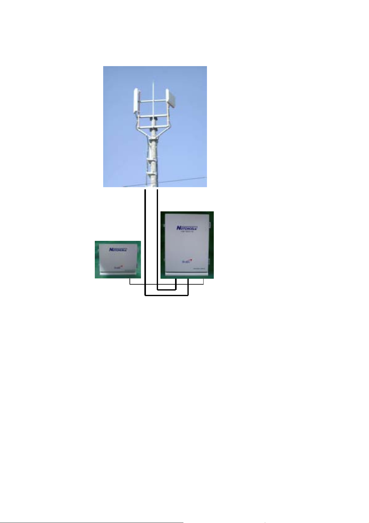
1 Overview
Å
Feeder Line
Installation of antenna
Å
Installation of Repeater
DC Power Cable
R-TRON NOTCHCELL repeaters are used to fill out uncovered areas in CDMA1900 mobile systems, such as
base station fringe areas, road tunnels, business and industrial buildings, etc.
A NOTCHCELL repeater receives signals from a base station, amplifies and retransmits the signals t o mobile
stations. Also it receives, amplifies and retransmits signals in the opposite direction. Both directions are served
simultaneously.
To be able to receive and transmit signals in both directions, the repeater is connected to a donor antenna
directed towards the base station and to a service antenna directed towards the area to be covered.
Control of the repeaters is performed using a desktop or notebook loaded with the R-TRON OMT, Operation
and Maintenance Terminal, which can communicate with the repeaters either locally or remotely via wireless
data modem. Remote operation can be performed either via CDMA net.
R-TRON Proprietary & Confidential Page 6
Page 7

System Description NOTCHCELL Repeater
To be able to control many R-TRON NOTCHCELL repeaters in common, there is a Sprint EMS center.
R-TRON NOTCHCELL Repeaters work as bi-directional amplifiers.
A repeater receives, amplifies, and retransmits signals downlink and uplink simultaneously, i.e. from the base
station via the repeater to the mobile stations and from the mobile stations via the repeater to the base station.
The repeater can be connected to a donor antenna directed towards the base station, and to a distributor
antenna directed towards the area to be covered. These antennas are c onnected to the repeater with type-N
connectors.
To prevent instability due to poor antenna isolation, R-TR ON has developed NOTCHCELL Repeater. R-TRON
NOTCHCELL Repeaters become clear of having superiority over the other RF repeaters in the world.
The R-TRON NOTCHCELL Repeaters are controlled by powerful microprocessors. Alarm and operational
status LEDs are visible on the bottom of the repeater.
The repeater works with convection cooling without fan.
Operational parameters, such as gain, power levels, alarm condition, Automatic Level Control condition, etc.
are set using a desktop or notebook and R-TRON OMT, which communic ate, locally via RS-232C cable, with
the repeater. Remote operation is performed via CDMA net.
R-TRON Proprietary & Confidential Page 7
Page 8
System Description NOTCHCELL Repeater
2 Repeater Design
2.1 System specification
2.1.1 Environmental conditions
Item Standard Remark
Power supply AC110V±20%, 50/60Hz±5%
or +24Vdc battery backup available
Operating temperature - 40 ~ +55 ℃
Storage temperature - 40 ~ +70 ℃
Humidity 95 %
Consumption power 400 W(Normal),
1200W(Max. In case of the Heater acts at
lower temperature)
Rainfall 100 mm/Hr
Water proof NEMA 4x
Wind pressure 60m/s
<Table 2-1> Environmental Conditions
2.1.2 System features
A. NOTCHCELL repeater
Item SPEC Remark
Frequency bandwidth 5MHz
Toward Handset (Down Link)
Toward BTS (Up Link)
Input range (dBm)
Max. Output power
Gain range (dB) 70 ~ 95dB Max. gain ±0.5dB
Gain control / Interval (dB) 25dB / 1dB
Noise figure
In band flatness 2dB max.
Absolute group delay 5㎲ max.
Interface RS-232 and Modem
VSWR 1:1.5 max.
Impedance 50Ω
RF connector (Antenna Port) N-Female
Size (W x H x D)
Weight
DL 40dBm (10W) / Total
UL 25dBm (0.31W) / Total
Maximum Gain 4dB max.
Minimum Gain 8dB max.
Main Box 450*635*243mm
PSU Box 450*384*265mm
Main Box Less than 43Kg(95lbs)
PSU Box Less than 25Kg(55lbs)
1945 ~1950MHz
~
1865
-55
-70 ~-45dBm(UL)
<Table 2-2> Repeater Features
1870MHz
~
-30dBm(DL),
Based on 3 carriers
Based on 3 carriers
R-TRON Proprietary & Confidential Page 8
Page 9

System Description NOTCHCELL Repeater
B. NOTCHCELL Antenna
Item
Donor ANT Service ANT
Frequency Range 1850 ~1910 MHz, 1930 ~ 1990 MHz
Band Width 60MHz, 60MHz
V.S.W.R 1:1.5
Gain 17 dBd
Half-Beam width (H) 20
Half-Beam width (V) 20
Front-to-back ratio
First-to-side ratio
Isolation
Impedance 50
Polarization Vertical Vertical
Max Power 200 W 200 W
RF connector 7/16” DIN-female 7/16” DIN-female
Size (W*H*D) 700*1000*150 mm
Rated Wind Velocity 60 m/sec 60 m/sec
Weight Less than 20 kg(44lbs) Less than 17 kg(38lbs)
Radiator Material Copper Copper
Radome Material Fiberglass Fiberglass
Tilt 0˚~ 15˚ 0
이하
±
1 dB 17 dBd ±1 dB
˚±3˚
˚±3˚
≥
45 dB
≥
13 dB
ANT Distance (Horizontal)
Ω
50
<Table 2-3> Antenna Features
SPEC
1:1.5
≥
13 dB (Upper)
≥
100 dB
310*1500*120 mm
이하
45
˚±5˚
˚± 2˚
8
≥
45 dB @180deg
≥
1.5m
˚
Ω
~ 15˚
Remark
@180
±
90deg
The repeater is housed in a cast aluminum chassis that is waterproof, class NEMA 4x, for outdoor use. The
chassis has a design suited for outdoor use as well as indoor use.
The chassis consists of a cabinet and a cover joined with hinges. The cabinet contains the repeater circuitry.
Inside the repeater, a number of amplifier boards are individually shielded and located under a metal cover that
can be folded out. These amplifier boards are different types depending on the supported system.
The followings are the Technical Specification of NOTCHCELL Repeater.
CAUTION:
The antenna used for this transmitter must not exceed 20.15dBi and must be installed to provide a minimum separation
distance of 3 meters from all persons.
R-TRON Proprietary & Confidential Page 9
Page 10
System Description NOTCHCELL Repeater
3 Repeater Configurations
The repeater system consists largely of the Main Box and PSU Box. The main modules or units of repeater are as
follows:
DPX (Duplexer), MC PA (Multi Carrier Power Amplifier unit), ARCU (Advanced Repeater Control Unit board),
ARIU (Advance Repeater Control Unit board), UDC (Up-Down Converter unit, with LNA), Arrestor, PSU (Power
Supply Unit), Heater Module, EMI/EMC Filter.
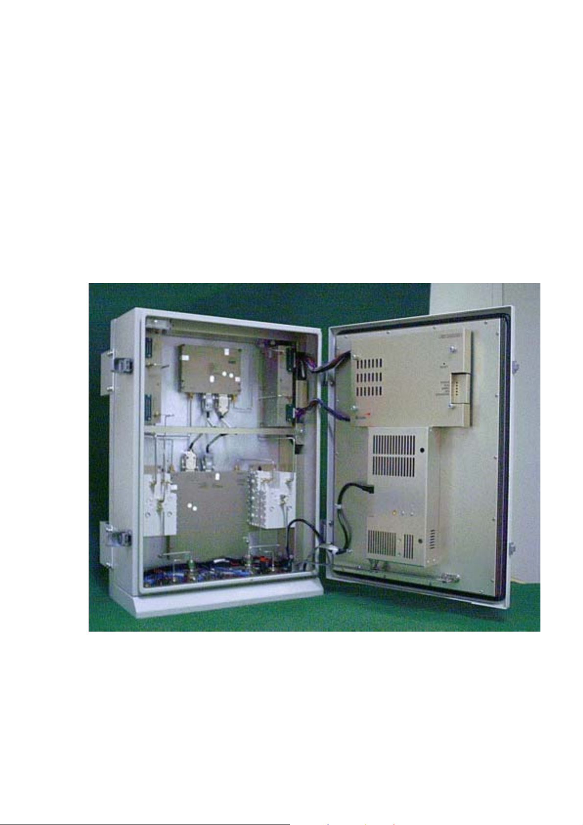
3.1 Main Box
The following is the picture of Main Box.
MCPA-UL
ARCU
UDC-UL UDC-DL
ARIU
DL-MCPA
Heat Module
DPX-BS DPX-MS
Arrestor Arrestor
Figure 1 Sub units in a band selective repeater (Main Box)
A cabinet for a band selective repeater is equipped with two pair of UDC (with LNA) and PA units, one pair for
downlink (DL) and one pair for uplink (UL). The described cabinet is equipped for bi-directional band selective
operation.
R-TRON Proprietary & Confidential Page 10
Page 11

System Description NOTCHCELL Repeater
3.2 PSU Box
Heat Module
EMI/EMC EMI/EMC
PSU
Figure 2 PSU Box
3.3 Sub Unit Overview
Functionally, repeaters are built up with several sub units. The sub units of main repeater are as follows:
Band selective repeaters can handle multi-carriers over a wide band. The bandwidth is adjustable. A band
selective repeater requires two UDC (with LNA) units and two PA units in the repeater.
One pair of UDC (with LNA)/PA units is for uplink signaling and one pair is for downlink signaling.
3.3.1 UDC (Up-Down Converter unit) with LNA
Figure 3 UDC-UL Figure 4 UDC -DL
R-TRON Proprietary & Confidential Page 11
Page 12

System Description NOTCHCELL Repeater
UDC converts (Down) a signal received from LNA and gets rid of signal which is out of the bandwidth range,
then converts (Up) again into the original frequency range and controls ‘Path Gain’.
3.3.2 MCPA (Multi Carrier Power Amplifier unit)
Figure 5 MCPA -UL
Figure 6 MCPA -DL
CDMA repeaters can be equipped with two MCPA that boosts the output gain with typically 35~40dB. PA (Power
Amplifier) amplifies RF signal received from UDC (Downlink) up to 50 dB and its Maximum RF input is 42 dBm in
terms of CDMA SFA standards.
R-TRON Proprietary & Confidential Page 12
Page 13

System Description NOTCHCELL Repeater
3.3.3 ARCU (Advanced Repeater Control Unit board)
Figure 7 ARCU
The ARCU board is the control unit of the repeater. The ARCU board is used to supervise and control operational
parameters such as gain control, ALC handling, etc. The ARCU takes care of alarms and the event log, password
and logon, and many other procedures.
3.3.4 DPX (Duplexer)
Figure 8 DPX-BS Figure 9 DPX-MS
The Duplexers are located in the lower part of the repeater cabinet. MS and BS duplexers are identical.
R-TRON Proprietary & Confidential Page 13
Page 14
System Description NOTCHCELL Repeater
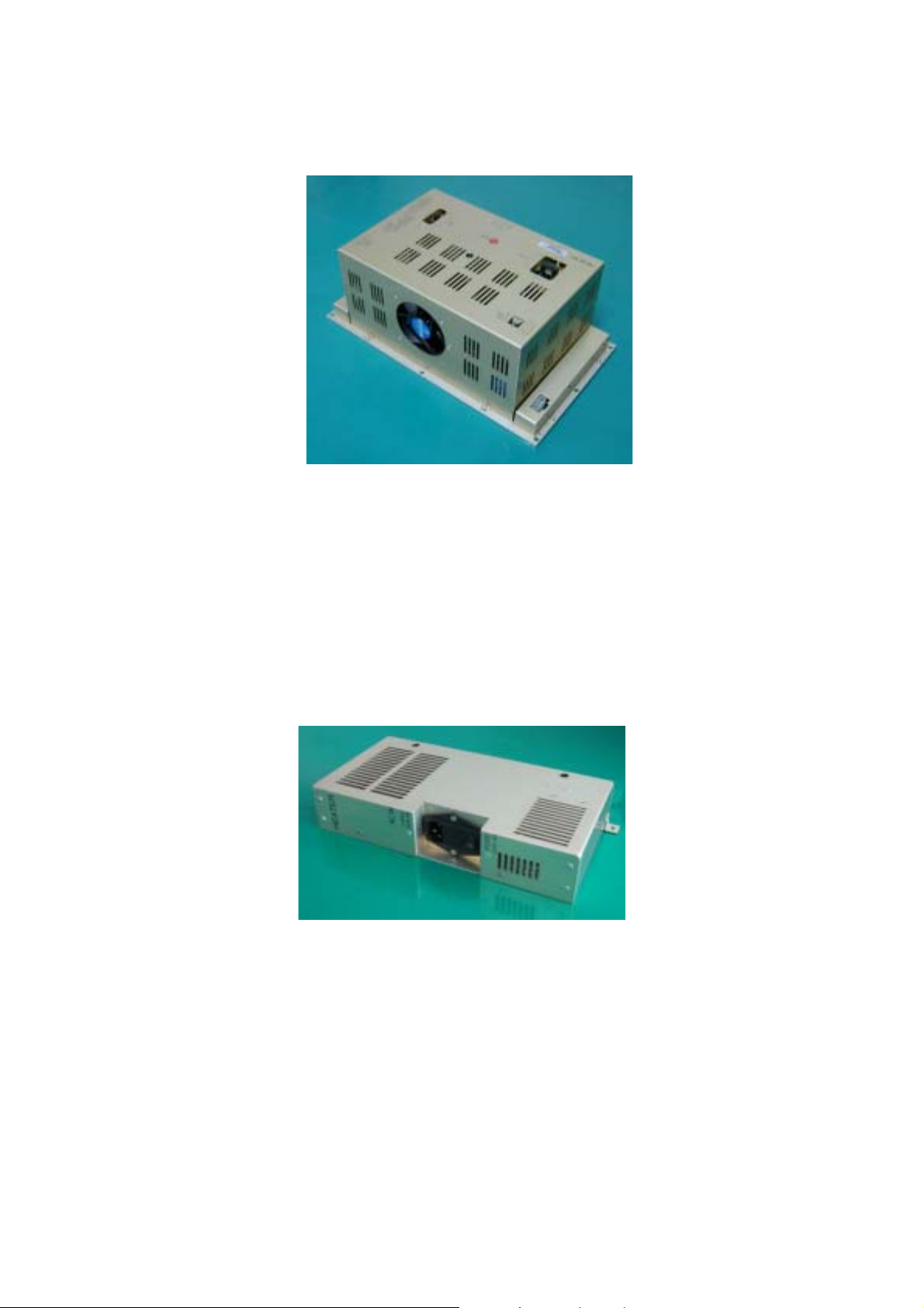
3.3.5 PSU (Power Supply Unit)
Figure 10 PSU
PSU receives AC 110V (Voltage) from outside and provides DC Power to each unit. In case AC Power shuts
down, PSU supplies power to each unit using battery box (+24v) which is connected to ‘BATT IN’ locating under
main repeater body. In case AC power is restored, the battery, connected to outside, is converted into being
charge with electricity automatically. (Battery Box is optional)
3.3.6 Heat Module
Figure 11 Heat Module
It installed to maintain stable characteristic of the repeater in cabinet inside in the low temperature. The having
fever heat capacity is a maximum 400Watt.
R-TRON Proprietary & Confidential Page 14
Page 15

System Description NOTCHCELL Repeater
3.3.7 ARIU (Advance Repeater Interface Unit board)
Figure 12 ARIU
BTS sends the alarms of Notch repeater and the operator can check and control.
3.3.8 Arrestor
Figure 13 Arrestor
Arrester uses a semiconductor varistor to protect equipment from lightning.
3.3.9 EMI/EMC Filter
Figure 14 EMI/EMC Filter
It use to prevent the noise ingredient is radiated with the spurious to happen to the outside in the repeater.
R-TRON Proprietary & Confidential Page 15
Page 16

System Description NOTCHCELL Repeater
4 Block Diagram
The main signal paths are described in general in the next section and detailed under each block diagra m.
4.1 Downlink signal path
The downlink signal path, i.e. from the base station through the repeater to the mobile station, is described for
NOTCHCELL repeater under the block diagrams on the following pages.
4.2 Uplink signal path
The uplink signal path, i.e. from the mobile station through the repeater to the base station, is identical to the
downlink path but the other way round. Only some levels and component values differ.
4.3 Band Selective Repeater
BTS
Donor
Donor
ANT
ANT
Arrester
Arrester
UL-30dB Test Port
Main Box
U D C / DL
U D C / DL
U D C / DL
ATT 1 ATT 2
ATT 1 ATT 2
ATT 1 ATT 2
Wireless
Wireless
Modem
Modem
(Option)
(Option)
12V
12V
27V
27V
PA / UL
PA / UL
PA / UL
:Data
:Data
:Power
:Power
12V
12V
RCU
RCU
Controller
Controller
12V
12V
UDC / UL
UDC / UL
UDC / UL
-20dB
-dB
Directional Coupler
Directional CouplerDirectional Coupler
Duplexer
/BS
Repeater State LED
Repeater State LED
RS-232C
RS-232C
Bluetooth
Bluetooth
(Option)
(Option)
12V
12V
LNA / DL
LNA / DL
Figure 15 Block Diagram of Band Selective Repeater
ATT 1ATT 2
ATT 1ATT 2
ATT 1ATT 2
AC
AC
Input
Input
12V
12V
PA / DL
PA / DL
EMI/EMC
EMI/EMC
EMI/EMC
FILTER
FILTER
FILTER
27V
27V
12V
12V
LNA / UL
LNA / UL
PSU Box
PSU Box
DL-30dB Test Port
DL-30dB Test Port
Duplexer
Duplexer
External Alarm
External Alarm
PSU
PSU
/MS
/MS
Distributor
Distributor
Distributor
ANT
ANT
ANT
Arrester
Arrester
Battery Box
Battery Box
(24V, Option)
(24V, Option)
Figure 15 shows a block diagram of a band selective repeater. This diagram is applicable to repeaters for CDMA
systems.
R-TRON Proprietary & Confidential Page 16
Page 17

System Description NOTCHCELL Repeater
4.4 Repeater Setup
The repeater parameters can be set locally by means of a desktop or notebook running OMT. The PC is
connected to the ARCU via the RS-232 PC port.
* Option (Bluetooth Adapter): When it is used, it enables wireless integration
5 Board and Unit Descriptions
5.1 MCPA for downlink
MAINAMP
FWDDETECT REVDETECT
ISOLATOR
RFIN
GAIN
CONTROL
DRIVEAMP
MAINAMP
Figure 16 Block diagram of Power Amplifier unit for downlink
MCPA amplifies RF signal received from UDC (Downlink) up to 50 dB a nd its Maximum RF input is 42 dBm in
terms of CDMA SFA standards.
Connection
Port Connected to
RF IN RF OUT on the UDC-DL board.
RF OUT DL on the DPX-MS duplex filter.
RF OUT
CON On the ARCU board
CON 27V port on the PSU unit
Specification
Item Specification Remarks
Frequency 1945MHz~1950MHz
Bandwidth 5MHz
Gain
50
±
0.5dB
Output Power 42dBm
I/O Port 1: GND 2: Over Power Alarm Normal: Low
R-TRON Proprietary & Confidential Page 17
Page 18

System Description NOTCHCELL Repeater
3: VSWR Alarm 5: Over Temp
6: PA On/Off 7: Cable Open
8: Transmit Power Monitor
9: Reflect Power Monitor
Mute Function
Power Detector 0.1 ~ 5V
Voltage DC 27V
RF connector Type-SMA, female
5V
⇒
Off, 0V⇒On
Fail: High
5.2 PA for uplink
Figure 17 Block diagram of Power Amplifier unit for uplink
PA (Power Amplifier) amplifies RF signal received from UDC (Downlink) up to 40dB and its Maximum RF input
is 27dBm in terms of CDMA SFA standards.
Connection
Port Connected to
RF IN RF OUT on the UDC-UL board.
RF OUT UL on the DPX-BS duplex filter.
CON On the ARCU board.
CON +27V on the PSU unit.
Specification
Item Specification Remarks
Frequency 1865MHz ~1870MHz
Bandwidth 5MHz
Gain
40
±
0.5dB
Output Power 27 dBm
R-TRON Proprietary & Confidential Page 18
Page 19

System Description NOTCHCELL Repeater
I/O Port
Mute Function
Power Detector 0.1 ~ 5V
Voltage DC 27V
RF connector Type-SMA, female
1: GND 2: Over Power Alarm
3: VSWR Alarm 5: Over Temp
6: PA On/Off 7: Cable Open
8: Transmit Power Monitor
9: Reflect Power Monitor
5V
⇒
Off, 0V⇒On
5.3 UDC for downlink
Normal: Low
Fail: High
Figure 18 Block diagram of Up-Down converter unit for downlink
The above product is Un-Down Converter for Downlink and it is composed of three parts (Down Converter, IF
and Up Converter)
Down Converter
Down Converter consists of RF level detector, BPF, Digital Atten, AMP and Analog Atten, Mixer. RF level
detector converts RF signal into DC, which is able to detect signal level. The first BPF removes signal out of
required bandwidth among the inputted signal from LNA and AMP compensates the loss from the first BPF.
Digital Atten, which is connected to Controller, operates to control Path Gain. Analog Atten is used for minute
control of Path Gain. Mixer converts RF into IF (IF-70MHz)
IF
IF is composed of Filter (LPF and SAW) and AMP. LPF removes spurious signal which is higher passing band
and SAW Filter gets rid of unwanted signal which is out of required bandwidth. AMP compensates loss which
occurs when signal passing through Filter.
R-TRON Proprietary & Confidential Page 19
Page 20

System Description NOTCHCELL Repeater
Up Converter
Up Converter consists of Mixer, AMP, BPF, Digital Atten, Analog Atten and RF level detector. Mixer is used to
convert IF (70 MHz) to Down Link Path RF Frequency. BPF is to remove signal out of service range. Digital
Atten operates connected to controller to control Path Gain.
LNA
Figure 19 Block diagram of Low Noise Amplifier unit for downlink.
This product is a low noise amplifier used for NOTCHCELL downlink. It is generally composed of RF block an d
Fault block (Alarm circuit).
RF block has approximately 30dB gain at CDMA1900 through 3-stage amplification, and its noise index is
0.9dB. Fault block is a circuit that detects current flowing in each TR of RF block.
Fault circuit detects current flowing in 1
set value due to the change of LNA environment, it generates TTL signal (5V).
Connection
Port Connected to
RF IN DL on the DPX-MS.
RF OUT RF IN on the PA-DL unit.
CON On the ARCU board
CON On the PSU unit.
Specification
Item Specification Remarks
Frequency 1945MHz ~1950MHz)
st
stage TR and 2nd & 3rd stage TRs. If TR current is less or more than
Bandwidth 5MHz
Gain
Voltage DC 12V
RF connector Type-SMA, female
24~49dB
±
0.5dB
Att. : 25dB
R-TRON Proprietary & Confidential Page 20
Page 21

System Description NOTCHCELL Repeater
5.4 UDC for uplink
Figure 20 Block diagram of Up-Down converter unit for uplink
The above product is Down Converter for Uplink and it is composed of three parts (Down Converter, IF a nd Up
Converter)
Down Converter
Down Converter consists of RF level detector, BPF, Digital Atten, AMP and Analog Atten, Mixer. RF level
detector converts RF signal into DC, which is able to detect signal level. The first BPF removes signal out of
required bandwidth among the inputted signal from LNA and AMP compensates the loss from the first BPF.
Digital Atten, which is connected to Controller, operates to control Path Gain. Analog Atten is used for minute
control of Path Gain. Mixer converts RF into IF (IF-70MHz)
IF
IF is composed of Filter (LPF and SAW) and AMP. LPF removes Spurious signal which is higher passing band
and SAW Filter gets rid of unwanted signal which is out of required bandwidth. AMP compensates loss which
occurs when signal passing through Filter.
Up Converter
Up Converter consists of Mixer, AMP, BPF, Digital Atten, Analog Atten and RF level detector. Mixer is used to
convert IF (70 MHz) to Down Link Path RF Frequency. BPF is to remove signal out of service range. Digital
Atten operates connected to controller to control Path Gain.
LNA
R-TRON Proprietary & Confidential Page 21
Page 22

System Description NOTCHCELL Repeater
Figure 21 Block diagram of Low Noise Amplifier unit for downlink.
This product is a low noise amplifier used for NOTCHCELL downlink. It is generally composed of RF block
and Fault block (Alarm circuit). RF block has approximately 30dB gain at CDMA1900 through 3-stage
amplification, and its noise index is 0.9dB. Fault block is a circuit that detects current flowing in each TR of RF
block. Fault circuit detects current flowing in 1
than set value due to the change of LNA environment, it generates TTL signal (5V).
Connection
st
stage TR and 2nd & 3rd stage TRs. If TR current is less or more
Port Connected to
RF IN UL on the DPX-MS.
RF OUT RF IN on the PA-UL unit.
CON On the ARCU board
CON On the PSU unit.
Specification
Item Specification Remarks
Frequency 1865MHz ~ 1870MHz)
Bandwidth 5MHz
Gain
Voltage DC 12V
RF connector Type-SMA, female
34~59dB
±
0.5dB
Att. : 25dB
R-TRON Proprietary & Confidential Page 22
Page 23

System Description NOTCHCELL Repeater
5.5 ARCU
Figure 22 Block diagram of ARCU
The ARCU board is the central board in the repeater, located in the repeater cabinet.
The ARCU board contains a microprocessor, main memory, flash memory for the ARCU software, NVRAM
memory for parameters and the event log , ports for local and remote communication, battery powered real-time
clock, etc.
The ARCU board is used to supervise and control operational parameters such as gain control, ALC handli ng, etc.
The ARCU takes care of alarms and the event log, password and logon, and many other procedures.
The real-time clock on the ARCU board is used for alarm and for the event log.
Connection
Port Connected to
J1 On the PSU board.
J2 On the PA-DL unit.
J3 On the PA-UL unit
J4 On the UDC-UL, UDC-DL unit
J5, J5-1 On the UDC-UL unit
J6, J6-1 On the UDC-DL unit
J7 On the door
J7-1 Not used
J9, J9-1 On the W/M (Wireless Modem)
R-TRON Proprietary & Confidential Page 23
Page 24

System Description NOTCHCELL Repeater
J11 On the PSU board
J12 RS-232 (Local OMT) on the bottom of repeater
J13 Consol for microprocessor.
J16 LAN for microprocessor
J21 Not used
5.6 ARIU
Figure 23 Block diagram of ARIU
ARIU Module does to do WNMS interconnection function through ARCU and Wireless Modem (Expedite C201).
Specification
Item Specification Remarks
Power Requirements DC 4.2V, DC3.3V
Regulator MIC29502BU
RS232 Converter MAX3233
R-TRON Proprietary & Confidential Page 24
Page 25

System Description NOTCHCELL Repeater
5.7 DPX
Figure 24 Block diagram of DPX
The Duplexers are located in the lower part of the repeater cabinet. MS and BS duplexers are identical.
Connection
DPX-MS
Port Connected to
ANT Distributor AN T on the botto m of repeater
DL RF OUT on the PA-DL unit
UL RF IN on the UDC (with LNA)-UL unit
MON MON on the bottom of repeater or other Units
DPX-BS
Port ` Connected to
ANT DON OR ANT on the bottom of repeater
DL RF IN on the UDC-DL unit
UL RF OUT on the PA-UL unit
MON MON on the bottom of repeater or ANT on the wireless Modem Unit
Specification
DPX-MS, DPX-BS
Item Specification Remarks
Bandwidth 3.75 MHz
Insertion loss 1.2dB
Flatness 1.0dB
DL: 1945.625MHz~1949.375MHz Frequency
UL: 1865.625MHz~1869.375 MHz
R-TRON Proprietary & Confidential Page 25
Page 26

System Description NOTCHCELL Repeater
Separation between DL/UL
frequency
RF connector Type-SMA, female
Coupling value
VSWR 1:1.3
100dB
Coupling: 20dB, 30dB, 40dB
Monitoring: 30dB
±
2dB
±
2dB,
R-TRON Proprietary & Confidential Page 26
Page 27

System Description NOTCHCELL Repeater
5.8 Arrestor
Figure 25 Block diagram of Arrestor
Arrester uses a semiconductor varistor to protect equipment from lightning
Specification
Item Specification Remarks
Frequency 1800MHz~2000MHz
Bandwidth 200MHz
Insertion loss 0.2dB
VSWR 1:1.2
Surge current
RF connector Type-N, female
1.2 x 50
㎲
, 6 kV / 3 kA
5.9 PSU
Figure 26 Block diagram of PSU
PSU receives and converts input power (AC 110V) into DC +27V or +12V. In case PSU is connected to outside
Battery, it provides automatic power back-up function when AC power input is shut off. When power level of a
R-TRON Proprietary & Confidential Page 27
Page 28

System Description NOTCHCELL Repeater
storage battery is lower than +21V (±1.0V), battery input power is shut down to protect battery and it is how to
Prevent the storage batter from the over-discharge.
The output power, as converting into AC_IN/Battery of Battery/AC_IN, operates in a proper way and supply the
stable power until the over-discharge function works.
Specification
Item Input Output
AC / DC
Efficiency More than 80%
Power factor More than 90%
Alarm
5.10 EMI/EMC Filter
±
Voltage
AC110v
50/60Hz
Current 15A 7A
AC fail
DC fail
Battery fail
20%
±
5%
Normal: Low, Abnormal: High
27V 12V
Output Voltage Variation Ratio:
less than
±
2%
Figure 27 Block diagram of EMI/EMC Filter
EMI/EMC Filter in all entrances of PSU Box prevents that various spurious and consecutiveness noise
ingredients that happen in Repeater are radiated to outside.
R-TRON Proprietary & Confidential Page 28
Page 29

System Description NOTCHCELL Repeater
It should be as most as possible near with power input/output port, and Wires do so that to do not become
overlap each other.
Also, must do so that high frequency resistance may minimize in grounding paper as possible when do
mounting to Repeater.
When fix EMI/EMC Filter to metal case for this, after improving electricity conductibility removing coats of paint
of contact part, do to ground in the nearest distance coming ground connection terminal.
In case of use continuously exceeding rating current or use exceeding operating temperature, its performanc e
and reliability are fallen.
Specification
Item Specification Remarks
Rated Voltage 250V AC/DC
Rated Current 20A
Rated Frequency 50/60Hz
Leakage Current 0.75Ma max. at 250V AC 50/60Hz
Insulation Resistance
Test Voltage AC 2000V between line to ea rth for 1 minute
Operating Temperature
Ω
min. AT 500V DC
200M
℃
~ +85℃
-25
5.11 Heater Module
Figure 28 Block diagram of Heater Module
Heater Module attached inside Main Box and PSU Box for normal action of equipment in limit low temperature
state because Repeater's operating temperature condition is '- 40 to -55
Specification
Item Specification Remarks
Input Power AC100V +/-20% 50/60Hz +/-5%
Current 5A max.
℃
'.
R-TRON Proprietary & Confidential Page 29
Page 30

System Description NOTCHCELL Repeater
Heater Operating Temperature
Heating Power 400watt
Size
Act: Board temperature below +15℃±5
Stem by: Board temperature Higher than +20
285
×
157 × 55
℃
5.12 Connection Ports
5.12.1 Loca l O M T port ; Main Box
PC port RS-232 is a LOCAL OMT port used for local PC communication. The connector is found to the bottom
of the cabinet. LOCAL OMT is a 3-pole MS connector.
C
A
B
5.12.2 AC IN ; Main Box
MS20-3P, Male
Figure 29 LOCAL OMT - PC connector pinning
A: Data from repeater to OMT
B: Data from OMT to repeater
C: GND
A PE
B L
C N
R-TRON Proprietary & Confidential Page 30
Page 31

System Description NOTCHCELL Repeater
5.12.3 AC IN ; PSU Box
MS22-2, Male
A PE
B L
C N
5.12.4 DC IN 24V ; PSU Box
*Use at DC power (or Battery) connection necessity by Backup in case of is shut off AC.
MS24-12, Male
A +
B Not used
C D Not used
E Not used
R-TRON Proprietary & Confidential Page 31
Page 32

System Description NOTCHCELL Repeater
NOTCHCELL Repeater
Copyright © 2004 R-TRON, Inc.
All Rights Reserved
Copyright of this manual belongs to R-TRON, Inc.
Reproduction, distribution or revision of part or all of contents in this
manual in any form without written permission of R-TRON, Inc. i s
prohibited.
The information in this manual is subject to change for the reason of
function improvement, design alteration, etc. without any prior notification.
System Description
R-TRON Proprietary & Confidential Page 32
 Loading...