

Page 1
APEX730
LTE Band Repeater
User’s Manual
Please read this manual before operating this product.
After you finish reading this manual, store it in a safe place for future reference.
Page 2

TABLE OF CONTENTS
1. GENERAL........................................................................................................................................................... 1
1.1 N
OTICE.............................................................................................................................................................................................1
1.2 S
AFETY PRECAUTIONS...................................................................................................................................................................2
1.3 V
ERSION HISTORY..........................................................................................................................................................................3
1.3.1 Manual Version History List
1.3.2 Firmware Version History List
1.3.3 WEB GUI Version History List
LOSSARY .......................................................................................................................................................................................4
1.4 G
.................................................................................................................................................3
.............................................................................................................................................3
.............................................................................................................................................3
2. INTRODUCTION............................................................................................................................................... 5
2.1 APEX730 ........................................................................................................................................................................................5
2.2 APEX730
2.3 C
OMPONENT....................................................................................................................................................................................6
2.3.1 APEX730
2.4 D
ESCRIPTION...................................................................................................................................................................................7
2.4.1 Overview
2.4.2 I
2.4.3 RFU (RF Unit)
2.4.4 Duplexer
2.4.5 PSU (Power Supply Unit)
2.4.6 NCU (Network Control Unit)
KEY FEATURES............................................................................................................................................................5
..................................................................................................................................................................................6
...................................................................................................................................................................................7
NTERNAL CONFIGURATION.................................................................................................................................................8
.........................................................................................................................................................................8
...................................................................................................................................................................................8
......................................................................................................................................................8
...............................................................................................................................................8
3. MECHANICAL INSTALLATION...................................................................................................................... 9
ONFIRM ITEM FROM LIST............................................................................................................................................................9
3.1 C
OUNTING.......................................................................................................................................................................................9
3.2 M
ROUNDING ................................................................................................................................................................................. 12
3.3 G
3.4 RF
3.5 P
CABLE CONNECTION ............................................................................................................................................................ 12
OWER ON.................................................................................................................................................................................... 13
4. GUI OPERATION............................................................................................................................................. 13
4.1 GUI
4.2 I
4.3 S
4.4 S
4.5 GUI
4.5.1 S
OPERATION FLOW CHART ................................................................................................................................................. 14
NTERNET NETWORK SETUP ...................................................................................................................................................... 15
4.2.1 Windows 7 (Refer to 5.9 for other versions of Windows)
YSTEM LOGIN............................................................................................................................................................................. 16
YSTEM SETUP............................................................................................................................................................................. 17
4.4.1 Time Setting
4.4.2 Network Setup
SYSTEM CONTROL.............................................................................................................................................................. 18
YSTEM CONTROL ............................................................................................................................................................. 19
........................................................................................................................................................................... 17
....................................................................................................................................................................... 17
........................................................................................ 15
Page 3

4.5.2 Operating Control
................................................................................................................................................................ 20
4.5.3 Alarm Control
4.5.4 Band Select
4.6 GUI
SYSTEM SETUP.................................................................................................................................................................... 22
4.6.1 Easy Setup
4.6.2 M
4.7 GUI
4.7.1 System
ANUAL GAIN SETTING ................................................................................................................................................... 24
STATUS.................................................................................................................................................................................. 27
..................................................................................................................................................................................... 27
4.7.2 Operating
4.7.3 Alarm
4.8 F
ILE UPDATE ................................................................................................................................................................................ 28
...................................................................................................................................................................................... 27
4.8.1 MCU Firmware, Web GUI Download
TT ACHMENT............................................................................................................................................................................... 30
4.9 A
5.9.1 Internet Network Setting
....................................................................................................................................................................... 21
............................................................................................................................................................................ 21
............................................................................................................................................................................. 22
............................................................................................................................................................................... 27
............................................................................................................................. 28
...................................................................................................................................................... 30
5. TROUBLESHOOTING .................................................................................................................................... 32
5.1 LED
5.2 GUI
5.3 C
ALARM................................................................................................................................................................................. 32
ALARM.................................................................................................................................................................................. 33
OMMUNICATION ALARM.......................................................................................................................................................... 35
6. SPECIFICATIONS............................................................................................................................................ 37
6.1 RF
6.2 E
6.3 E
6.4 M
CHARACTERISTICS................................................................................................................................................................ 37
NVIRONMENTAL SPECIFICATION............................................................................................................................................. 37
LECTRICAL SPECIFICATION...................................................................................................................................................... 38
ECHANICAL SPECIFICATION.................................................................................................................................................... 38
7. APPENDIX........................................................................................................................................................ 39
7.1 US
7.2 W
7.3 R
LTE CHANNEL....................................................................................................................................................................... 39
ARRANTY................................................................................................................................................................................... 41
ETURN MATER IAL AUTHORIZATION (RMA) PROCEDURE.................................................................................................. 42
Page 4

1. General
1.1 Notice
Trademark
R-tron is a registered trademark of R-tron Inc.
Other products and company names mentioned here in this manual might be trademarks or trade names
of their respective owners.
Copyright
Copyright © R-tron Inc. 2000-2011
All Rights Reserved
Any reproduction, distribution, or revisions of any or all portions of this manual is prohibited without
written permission from R-tron Inc.
Notice
This document describes the specifications, installation, and operation of the APEX730 repeater.
Hardware and software mentioned in this document are subject to continuous development and
improvement. Consequently, there may be minor discrepancies between the information in the document,
performance, and design of the product.
Specifications, dimensions, and other statements mentioned in this document are subject to change
without notice.
Questions or Comments
Address: R-tron Inc. 6402 College Boulevard, Overland Park, KS 66211
Phone: +1-913-344-9977, 1-888-317-8766
Fax: +1-913-344-9988
e-mail: info@r-tronamerica.com
Website: www.rtronamerica.com
APEX730 USER MANUAL V1.0.00 Tech Support: 1-888-317-8766
1
Page 5
1.2 Safety Precautions
Opening the APEX730 equipment could result in electric shock and may cause severe injury.
Connect the equipment frame ground to the building ground.
Operating the APEX730 with antennas in very close proximity facing each other can lead to
severe damage to the repeater.
RF EXPOSURE INFORMATION
A minimum separation distance of 7.9 inches (20cm) must be maintained between the user and
the external antenna of the repeater to satisfy FCC RF exposure requirements. For more
information about RF exposure, please visit the FCC website at www.fcc.gov
This equipment is for indoor use only and enables the communication wiring to communicate
inside the building.
APEX730 USER MANUAL V1.0.00 Tech Support: 1-888-317-8766
2
Page 6
1.3 Version History
1.3.1 Manual Version History List
Revision History
Approval Ver. Issue Ver.
V1.0 V1.0 2011. 06. 15 Initial Version
Date Item/Description Reason
1.3.2 Firmware Version History List
Revision History
Approval Ver. Issue Ver.
V1.0.00 V1.0.00 2011. 06. 15. Initial Version
Date Item/Description Reason
1.3.3 WEB GUI Version History List
Revision History
Approval Ver. Issue Ver.
V1.0.00 V1.0.00 2011. 06. 15 Initial Version
Date Item/Description Reason
APEX730 USER MANUAL V1.0.00 Tech Support: 1-888-317-8766
3
Page 7
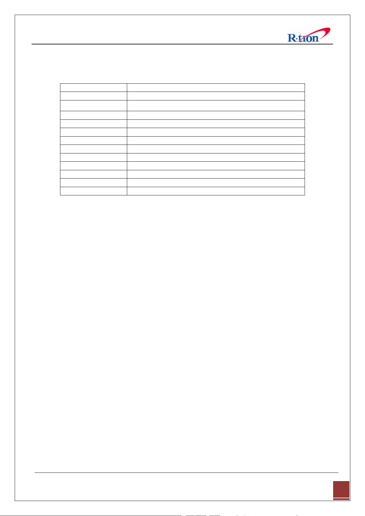
1.4 Glossary
The following is a list of abbreviations and terms used in this manual.
Abbreviation Definition
AC Alternating Current
LTE
DC Direct Current
DL Downlink
GUI Graphic User Interface
LED Light Emitting Diode
PSU Power Supply Unit
RF Radio Frequency
UL Uplink
VSWR Voltage Standing Wave Ratio
NCU Network Control Unit
MCU Main Control Unit
AGC (Automatic Gain Control)
AGC prevents the repeater from exceeding its maximum output power by reducing the gain
automatically. AGC is used to adjust the gain to an appropriate level for a range of input signal
levels
.
ASD (Automatic Shutdown)
ASD helps protect the amplifier from over load. ASD helps protect the network by preventing
excessive signal output power.
There are three parameters: ASD Level, ASD Time, and ASD Iteration.
If the output power exceeds higher than the “ASD LEVEL”, the repeater will shut down for “ASD
TIME” seconds. If shutdown repeats “Iteration” times, the repeater will require manual re-start.
Long Term Evolution
APEX730 USER MANUAL V1.0.00 Tech Support: 1-888-317-8766
4
Page 8
2. Introduction
2.1 APEX730
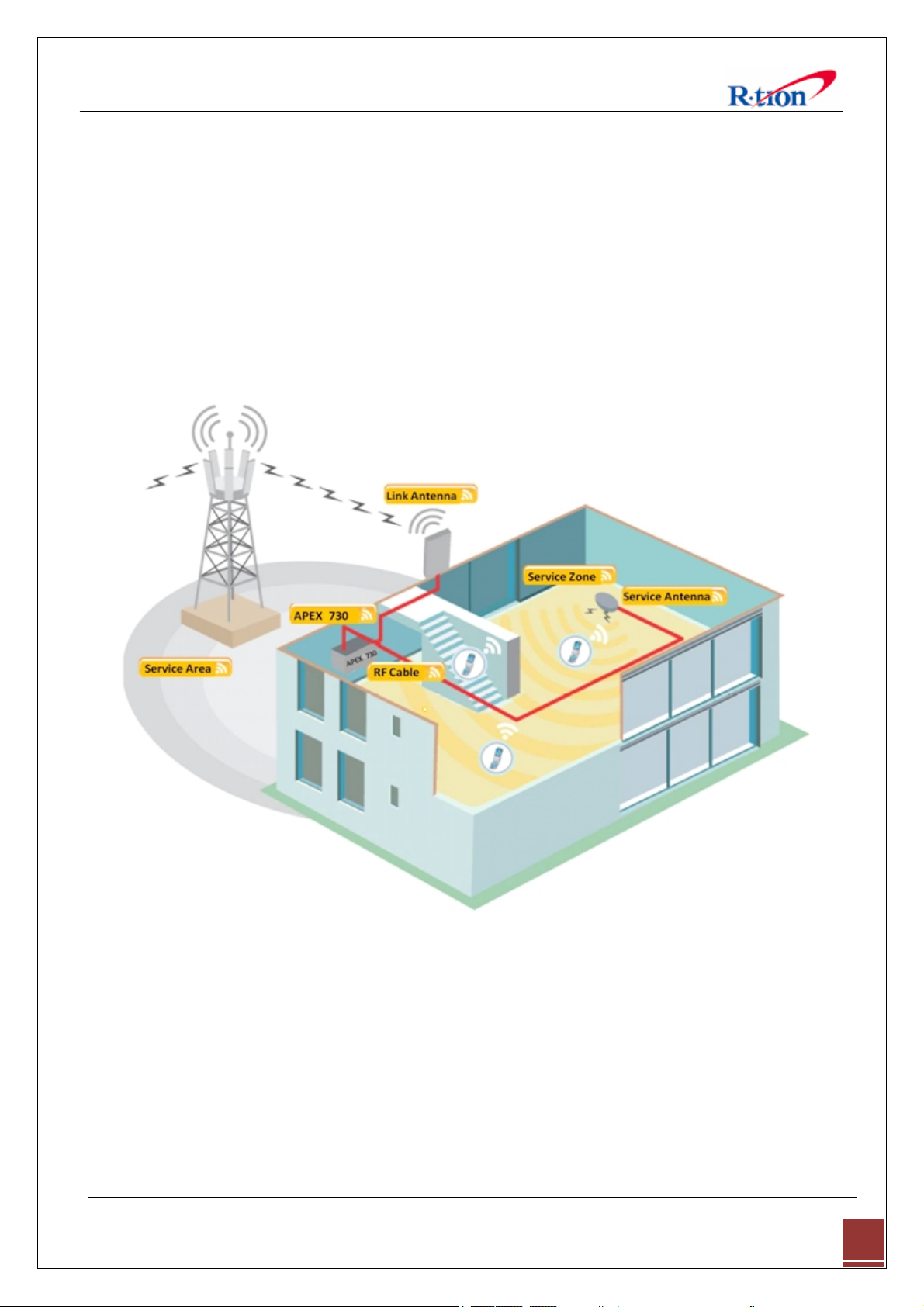
APEX730 is used to fill out areas in APEX systems, such as base station fringe areas, business
and industrial building, etc.
APEX730 receives signals from a base station, amplifies and retransmits the signals to the
mobile stations. It also receives, amplifies and retransmits signals in the opposite direction. Both
directions are served simultaneously with the following features:
< Basic Organization >
2.2 APEX730 Key Features
◈ Design
APEX730 USER MANUAL V1.0.00 Tech Support: 1-888-317-8766
5
Page 9
- Digital filtering allows for customized channel selections.
- Digital filtering high quality, out of band rejection, and high performance
◈ User friendly design.
- Local monitoring and control through the Web GUI interface
- Remote monitoring and control through the Web GUI interface.
- Reports the status of connection as a function of SNMP regularly and reports an alarm if the
event occurred.
◈ Protection function
- Easy setup
- Isolation Check
- Auto Gain Control
- Auto Shutdown
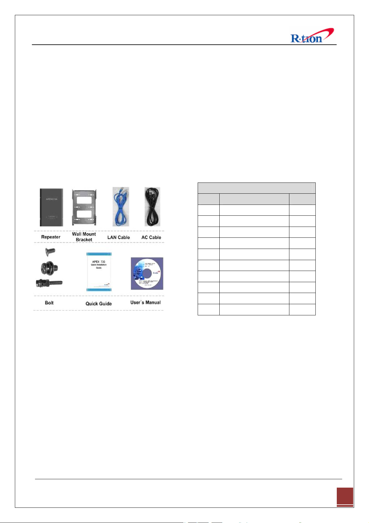
2.3 Component
2.3.1 APEX730
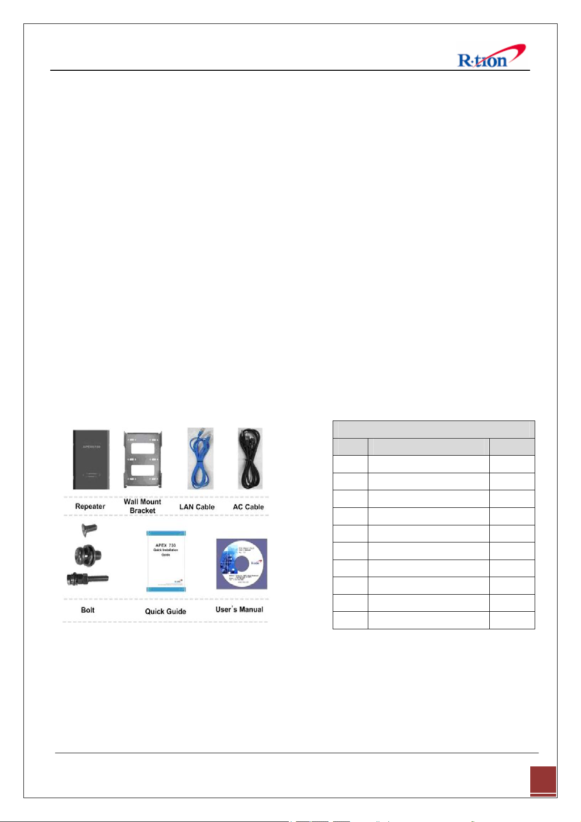
APEX730 Package
Index Items Q’ty
1 Repeater 1
2 Wall Mount Bracket 1
3 LAN Cable 1
4 AC Cable 1
5 Bolt (M4*8mm) 2
6 Bolt (M6*12mm) 4
7 Bolt (16/5*50mm) 4
8 Direct LAN Cable 1
9 Quick Guide 1
10 User’s Manual CD 1
APEX730 USER MANUAL V1.0.00 Tech Support: 1-888-317-8766
6
Page 10
2.4 Description
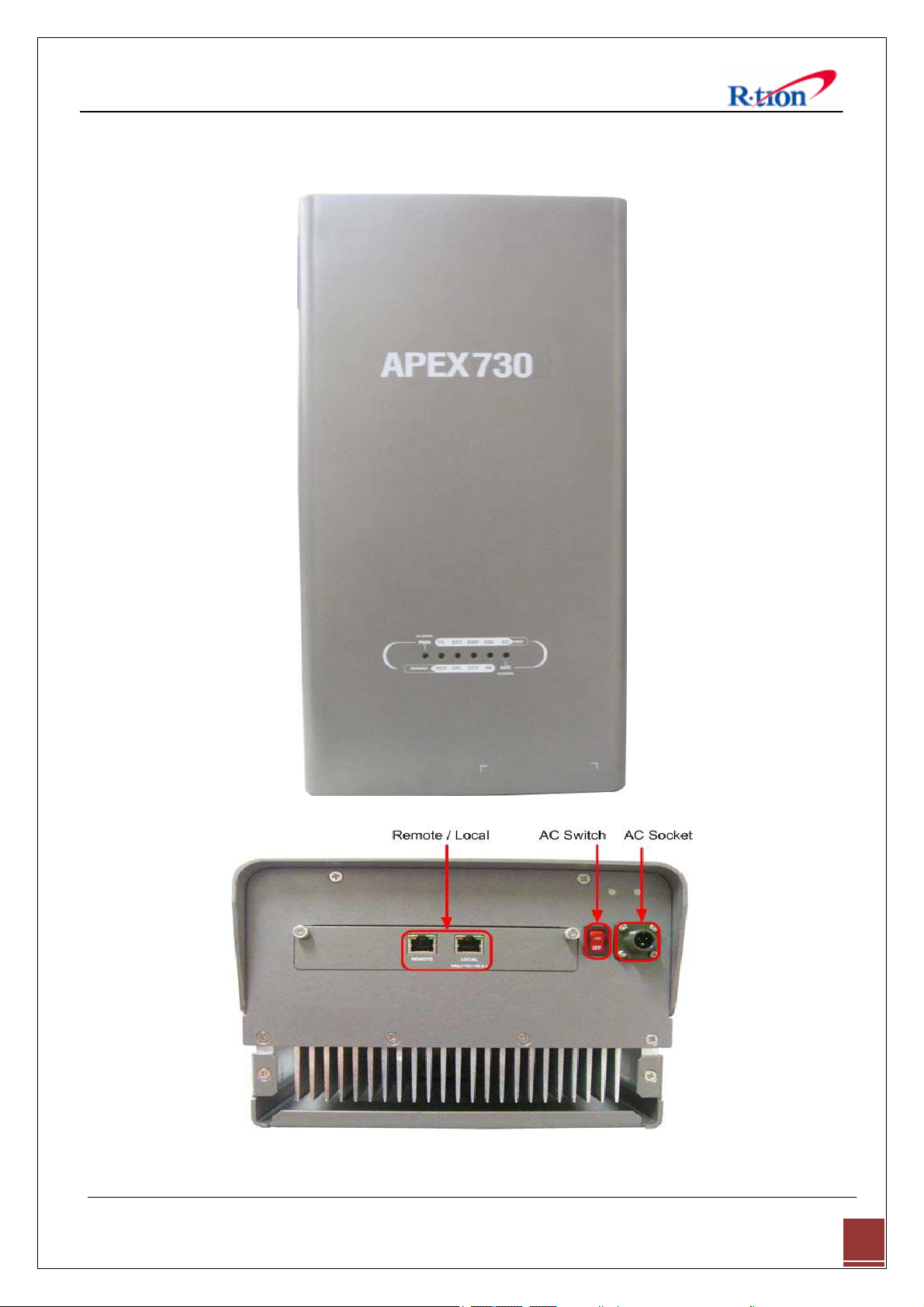
2.4.1 Overview
APEX730 USER MANUAL V1.0.00 Tech Support: 1-888-317-8766
7
Page 11
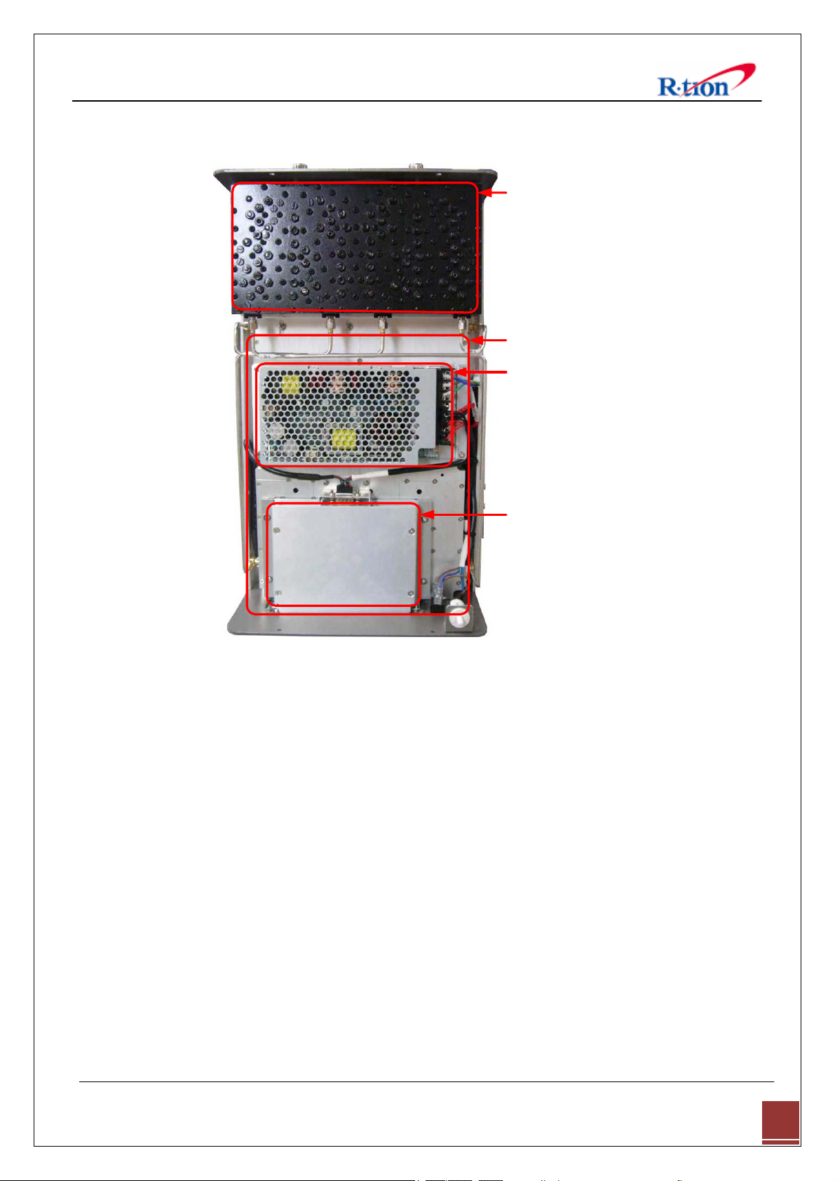
2.4.2 Internal Configuration
2.4.3 RFU (RF Unit)
The RFU (RF Unit) is a bi-directional amplifier that sharply filters out unwanted noise.
2.4.4 Duplexer
A duplexer is a device that combines two or more signals onto a common channel or
medium to increase its transmission efficiency.
2.4.5 PSU (Power Supply Unit)
The AC-DC adaptor supplies a steady DC power to the APEX730 equipment by drawing
power from the general in-wall AC outlets.
2.4.6 NCU (Network Control Unit)
The NCU (Network Control Unit) is the control unit of the APEX730. The NCU controls and
monitors operational parameters, alarms, records event and performs many other functions.
APEX730 USER MANUAL V1.0.00 Tech Support: 1-888-317-8766
8
Page 12
3. Mechanical Installation
The installation procedure is as follows:
• Confirm Items from List
• Mounting
• Grounding
• RF Cable Connection
• Power On
3.1 Confirm Item from List
APEX730 Package
Index Items Q’ty
1 Repeater 1
2 Wall Mount Bracket 1
3 LAN Cable 1
4 AC Cable 1
5 Bolt (M4*8mm) 2
6 Bolt (M6*12mm) 4
7 Bolt (16/5*50mm) 4
8 Direct LAN Cable 1
9 Quick Guide 1
10 User’s Manual CD 1
3.2 Mounting
Step 1 Drill holes directly through the template. Attach the mounting bracket to the wall using
provided bolts (16/5*50mm) or extra screws.
APEX730 USER MANUAL V1.0.00 Tech Support: 1-888-317-8766
9
Page 13
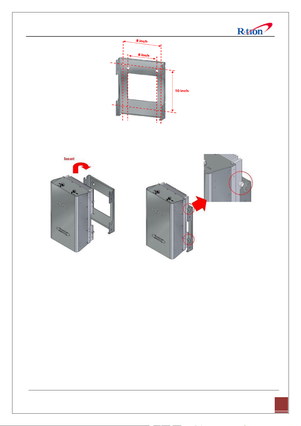
Step 2 Lean the APEX730 to hang the topside of the Guide Ring on the mounting bracket, and
push toward the wall to mount.
Step 3 Fix the repeater using the 4 bolts (M6*12mm) provided.
APEX730 USER MANUAL V1.0.00 Tech Support: 1-888-317-8766
10
Page 14
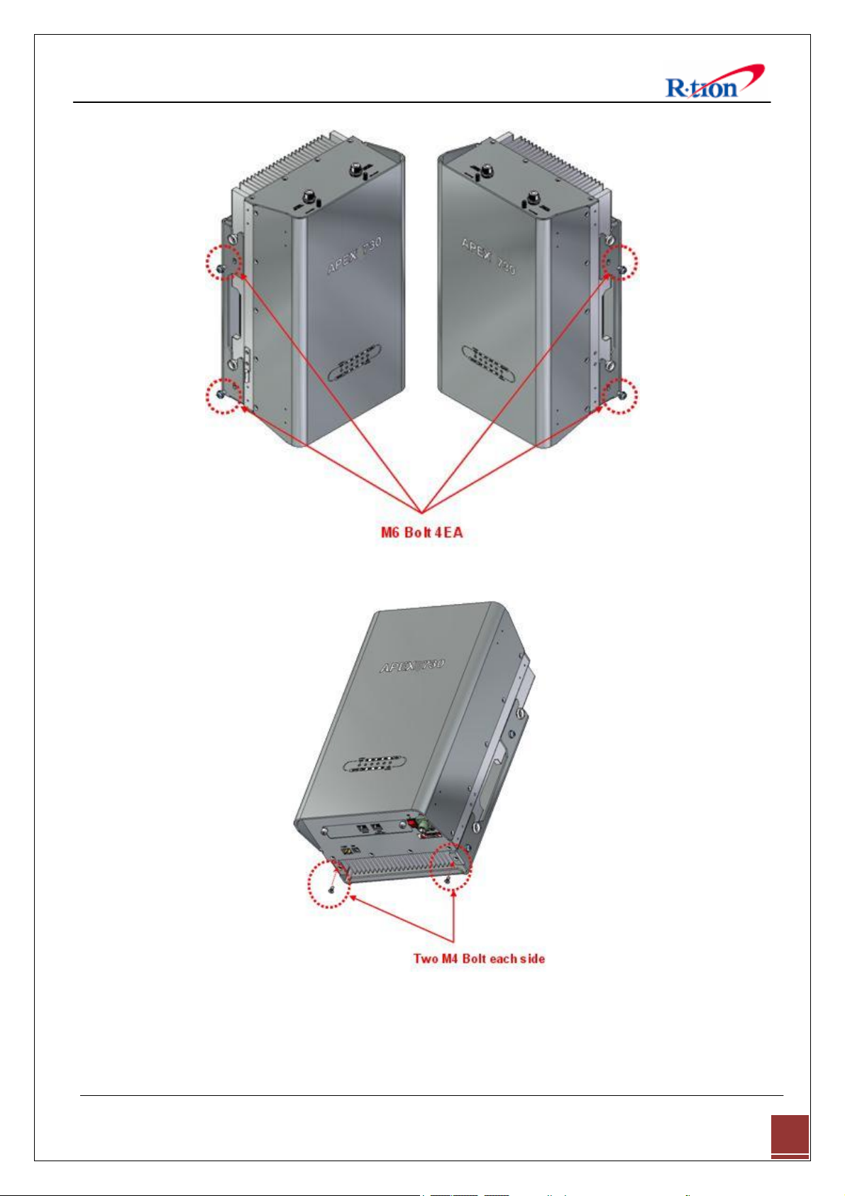
Step 4 Fix the repeater using the 2 Bolts (M4*8mm) provided.
APEX730 USER MANUAL V1.0.00 Tech Support: 1-888-317-8766
11
Page 15

3.3 Grounding
Step 1: A rod on the left side is intended
for a building ground.
Step 2: Connect the ground cable to the
rod.
3.4 RF Cable Connection
Step 1: Connect a cable from the donor antenna to the Donor Antenna Port.
Step 2: Connect a cable from a repeater’s service antenna to the Sever Antenna Port.
APEX730 USER MANUAL V1.0.00 Tech Support: 1-888-317-8766
12
Page 16

3.5 Power On
Notice: Antenna cables must be installed before connecting AC Power.
Step 1: Connect the power cord to the Repeater
Step 2: Plug the power cord into a wall outlet.
Step 3: Turn the red power button on
Step 4: Check if the green LED at the Top turns
on.
4. GUI Operation
APEX730 operates on a customer provided PC based platform with the following system
requirements:
• Windows® XP or Windows® Vista, Windows 7
• Internet Explorer 6.0(Recommended) or higher
• 128 MB RAM or higher
• Pentium Ⅲ processor or higher
APEX730 USER MANUAL V1.0.00 Tech Support: 1-888-317-8766
13
Page 17
• RJ-45 Cable required
g
y
y
g
4.1 GUI Operation Flow Chart
Setting in order to acquire the IP
address automaticall
.
-
APEX730 operation access to
Web GUI and Lo
in.
1. Time Setting
The user can control the repeater locally using the built-in WEB GUI.
Set the center frequency and bandwidth.
2. System Information Input
Input Cascade Code
and Location Information.
2. Isolation Check
Isolation will calculate the Available
Maximum Gain.
3. Ethernet Settin
IP address and SNMP IP Input.
4. Manual Control
AGC automatically assigns gain.
Gain value set by User.
[5] GUI Status Check
You can see s
stem, operating, and alarm information on Status page.
APEX730 USER MANUAL V1.0.00 Tech Support: 1-888-317-8766
14
Page 18

4.2 Internet Network Setup
4.2.1 Windows 7 (Refer to 5.9 for other versions of Windows)
Step 1: Click the Start button and select Control
Panel.
Step 3: Click Network and Sharing Center. Step 4: Click View status of Local Area Connection.
Step 2: Click Network and Internet.
Step 5: Click Properties and a caution pop-up
window will appear. Click OK.
Step 6: Select Internet Protocol Version 4 (TCP/IPv4)
and click Properties.
APEX730 USER MANUAL V1.0.00 Tech Support: 1-888-317-8766
15
Page 19
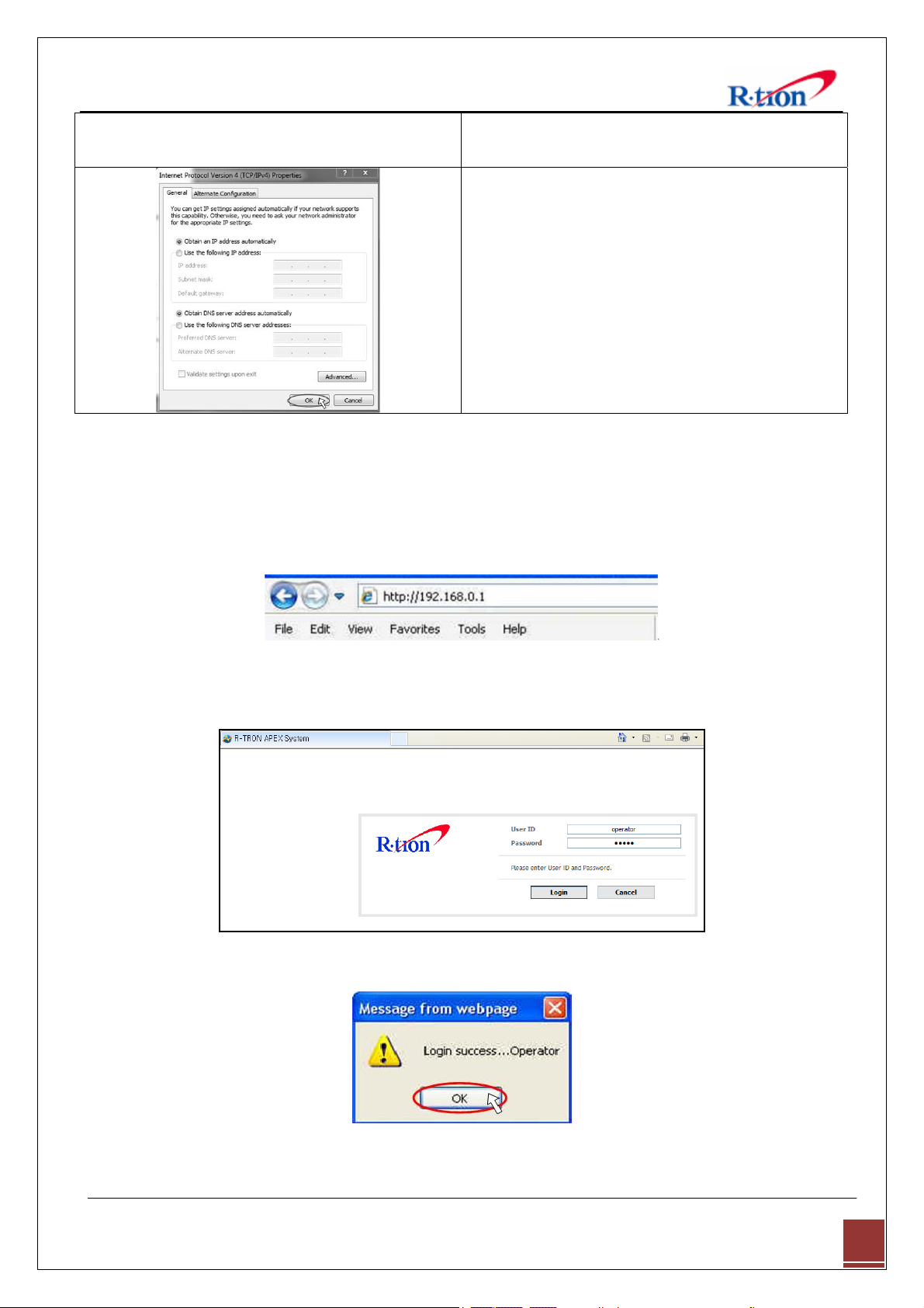
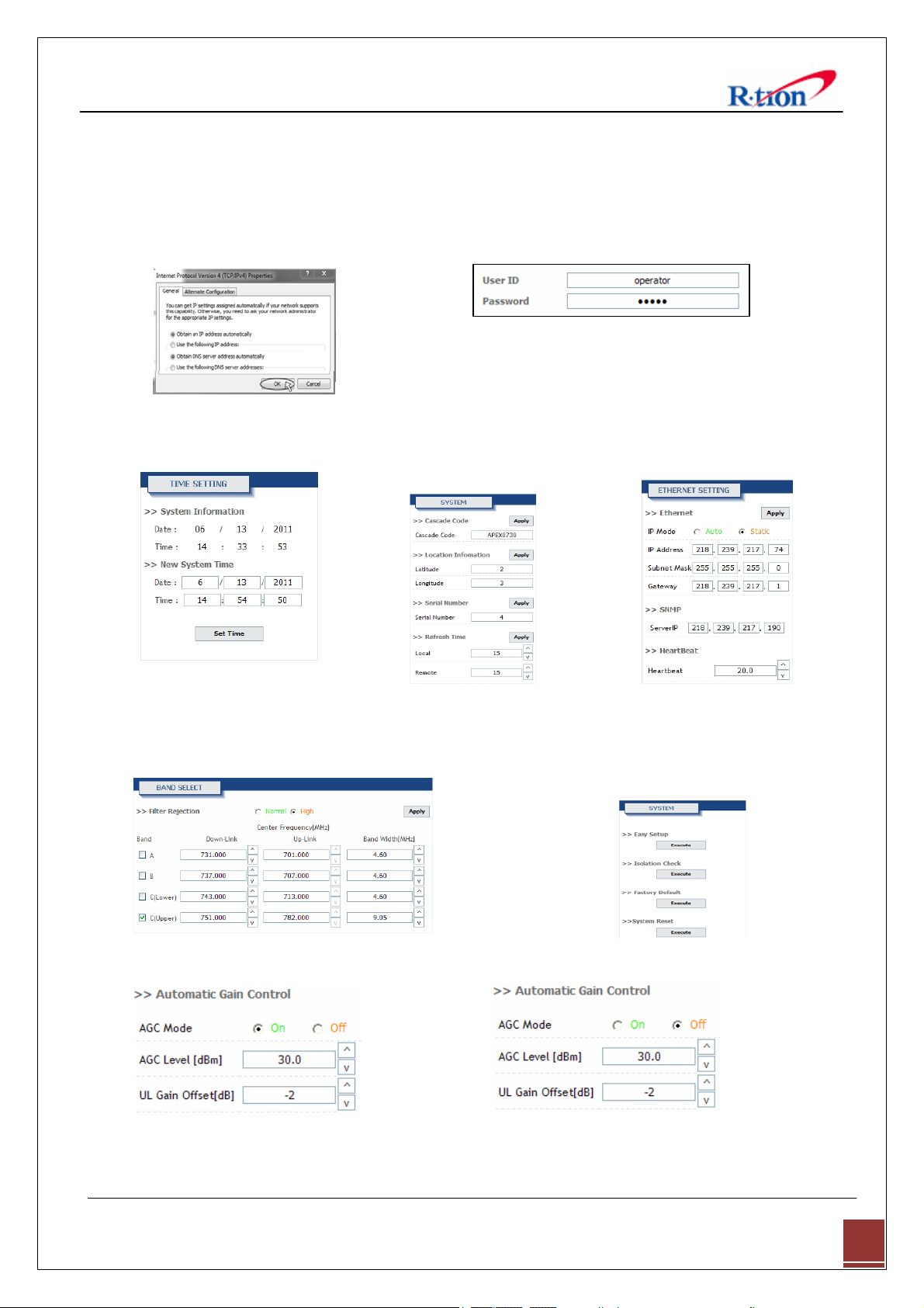
Step 7: Check Obtain an IP address automatically
Step 8: Close all windows.
and click OK.
4.3 System Login
For APEX730 operation access, go to Web GUI and Log in.
Step 1. Open your Web browser and type http://192.168.0.1 into the URL address box.
Then press the Enter key.
Step 2. Confirm a User ID and type the password into the password box. User ID is “operator”,
Type “rtron” for the password and then click OK.
Step 3. The pop-up message for the login success will appear. Click OK.
Step 4. When the login process is complete, the initial screen will appear.
APEX730 USER MANUAL V1.0.00 Tech Support: 1-888-317-8766
16
Page 20

4.4 System Setup
When you click Network you can set up User Note, Comment, Ethernet, and time setting.
4.4.1 Time Setting
The time will automatically set to your PC time when you click the set time
In the above page, you can set system time and update time-related information.
4.4.2 Network Setup
<Network Set-ups>
¾ SYSTEM
• Cascade Code: Type the pre-assigned cascade code. Otherwise, you cannot access the
system setup.
¾ ETHERNET SETTING
APEX730 USER MANUAL V1.0.00 Tech Support: 1-888-317-8766
17
Page 21

• Ethernet IP Mode / IP Address: Enables you to set a connection mode for the
network connected to the APEX730 remote LAN port. When you “select” Auto, the
device automatically assigns the IP address. When you select “Static”, it is possible to
set an IP address of your choosing.
• SNMP: In order to send Heartbeat and alarm related information to a remote
monitoring server, you can set a server IP address. The factory default IP address is
10.22.25.15.
• Heartbeat Interval: Sets the time to transmit the Heartbeat to the NMC Server.
(Default value is 20 minutes.)
4.5 GUI System Control
APEX730 USER MANUAL V1.0.00 Tech Support: 1-888-317-8766
18
Page 22

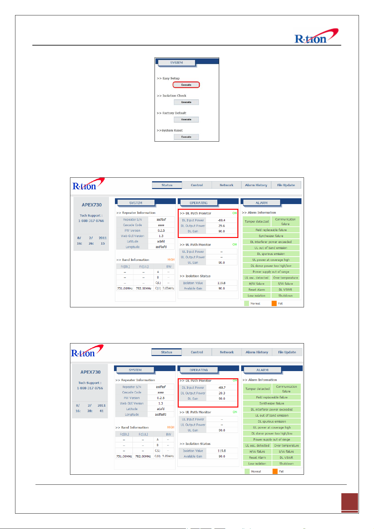
4.5.1 System Control
• Easy Setup is a fast start function. The function measures isolation, detects input level and
assign gain to achieve maximum output power. The function ends with the repeater set to
amplify siganals in both directions within the confines of the band selection. Before runing
easy setup, set the center frequency and bandwidth
Maximum output power requires at least -60dBm input power and suficient antenna
isolaiton.
• Isolatoin Check can be executed at anytime to measure isolation between the donor and
server antennas. Isolation Check momentarily disables service. Isolation check automatically
runs when factory default is initiated.
• Factor y Default restores the amplifier to its initial state. The function ends with amplifiers
off, AGC mode off, gain set to minimum(60dB) and UL gain offset set to 0dB. Band
sellection and all other system parameters are not changed. The featurs is usefull in claering
abnormal conditions.
• System Reset cycles the microporcessor unit. The function is similar to switching off/on the
repeater power switch.
APEX730 USER MANUAL V1.0.00 Tech Support: 1-888-317-8766
19
Page 23

4.5.2 Operating Control
• DL and UL Path Control allows the user to toggle on or off the power amplifiers.
• DL and UL Gain is available when AGC mode is off. The user may enter gain values
manually. Manual gain control is an alternative to automatic gain control(AGC). Manual gain
is disabled (grayed out) when AGC mode is on. Gain cannot be controlled manually above
the available gain found on the status page. The system will not allow gain to be increased
such that maximum output power(30dBm) is exceeded.
• Gain Tracking sets UL gain equal to DL gain. The feature helos maintain forward and
reverse link balance. The function control is grayed out when AGC mode is on.
• Automatic Gain Control :
- In contrast to manual gain control, automatic gain control (AGC) sets gain such that the
desired amplifier output level (dBm) is automatically set.
- The user controls gain by adjusting the AGC level. The user may set the level from 0dBm to
30dBm. AGC can be used to control the signal level radiated from the server antenna.
- AGC may also be user to match the repeater to a DAS (distributed antenna system). AGC
level may be restricted by available gain and DL input power.
• UL Gain offset is used in conjuction with AGC to reduce the amount of amplification in the
reverse direction (uplink). In the cases UL offset is set to -2dB.
• Automatic Shutdown (ASD):
- ASD temporarily shuts down the amplifier if the ASD level is exeded. It is not necessary to
turn off ASD. ASD events are stored in the alarm hostory log. Repeated ASD events will
APEX730 USER MANUAL V1.0.00 Tech Support: 1-888-317-8766
20
Page 24

evenually shutdown the amplifier permanently and trigger the external shutdown lamp.
- ASD Level is set to 33dBm by default. It is not necessary to change the default level.
4.5.3 Alarm Control
• Alarm response time may be set between 1 and 5 minutes.
• Alam Mask allows the user to customize the type of alarms sent to the SNMP server when
remote monitoring is in use.
4.5.4 Band Select
• Band select sets the digital filter to the center frequency and bandwidth of the local
service for which the repeater is intended to amplify. Likewise, all other signals outside of
the selected Center Frequency and Bandwidth are rejected.
• The user can select one, two three distinct sections within the LTE band. Each of the 1st,
2nd and 3rd filter blocks can be set to 4.52MHz or 9.02MHz of Bandwidth. Only the
downlink center frequency is set by the user. The uplink center frequency are automatically
set in acordance with the downlink frequencies.
APEX730 USER MANUAL V1.0.00 Tech Support: 1-888-317-8766
21
Page 25

4.6 GUI System Setup
4.6.1 Easy Setup
Step 1. Click Apply after setting Center Frequency and Band Width in use.
Step 2. Input AGC Level desired and click Apply.
1) AGC Level 30dBm 2) AGC Level 25dBm
Step 3. Easy Setup proceeds to:
• Data Initial execution
• Isolation Test exeduted
• Calculation of Available Maximum Gain by the isolation
• DL/UL Path On
• AGC On to obtain DL Output Power AGC Level or Maximum Gain 90dB
• ASD On
• AGC Off
• Easy setup takes about 60seconds.
APEX730 USER MANUAL V1.0.00 Tech Support: 1-888-317-8766
22
Page 26
Click Execute button of Easy Setup
Result 1. Constant Maximum DL Output Power 30dBm (AGC Level 30dBm)
If the DL input Power ≥ -60dBm
Result 2. Constant Maximum DL Output Power 20dBm (AGC Level 20dBm)
If the DL input Power ≥ -71dBm
APEX730 USER MANUAL V1.0.00 Tech Support: 1-888-317-8766
23
Page 27

4.6.2 Manual Gain Setting
4.6.2.1 AGC mode On Setting
Step 1. Repeat Step 1 through Step 2
Step 2. Isolation Check
The Isolation will calculate the Available Maximum Gain which defines the maximum gain
to be setup.
Click Isolation
Step 3. AGC must be turned on. AGC automatically assigns gain in accordance with AGC level.
Use AGC level to increase or decrease gain.
(Gain Offset is a gain differential between DL Output gain and UL output gain.)
Ex>AGC Level 30dBm, Gain Offset -3dB → DL Gain 90dB, UL Gain 87dB
AGC Level 25dBm, Gain Offset 0dB → DL Gain 85dB, UL Gain 85dB
APEX730 USER MANUAL V1.0.00 Tech Support: 1-888-317-8766
24
Page 28

Step 4. Tu rn o n th e DL and UL path controls.
4.6.2.2 AGC mode Off setting
When you want to set gain value not using Auto Gain control refer to the following.
Step 1. For manual gain control AGC must be turned off.
APEX730 USER MANUAL V1.0.00 Tech Support: 1-888-317-8766
25
Page 29

Step 2. The user can select any gain value as long as it does over-drive the amplifier or exceed
isolation requirements. Gain is automatically limited where conditions do not permit high
gain. Select the DL and UL Gain values. Tu rn o n th e DL and UL path controls.
APEX730 USER MANUAL V1.0.00 Tech Support: 1-888-317-8766
26
Page 30
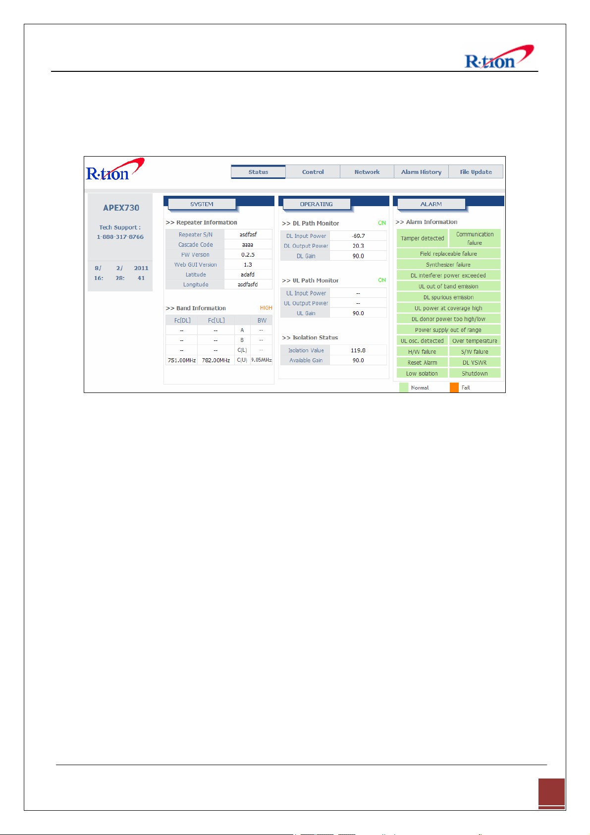
4.7 GUI Status
The status page display system, control, and alarm information.
When you set any value on the Control page the change will be reflected on Status page.
<Status>
4.7.1 System
• Firmware version and location are displayed under Repeater Information.
• The Band Information setting, set from the control page, is shown in bold font.
4.7.2 Operating
• DL Path Monitor displays input from the donor antenna circuit, output power at repeater
server antenna port, and downlink amplifier gain.
• UL Path Monitor displays input from the server antenna circuit, output powr at repeater
donor port, and uplink amplifier gain.
• Isolation Status shows isolation value (dB) between the donor antenna and server antennas.
• Available gain allowed by isolation measurement. Available gain is derived from the
antenna isolation value plus 15dB. Full system gain (90dB) is available if the antenna
isolation value is at least 105dB.
4.7.3 Alarm
• If an alarm occurs, the alarm LED on the repeater will turn on.
APEX730 USER MANUAL V1.0.00 Tech Support: 1-888-317-8766
27
Page 31

Alarms shown on the status page will have orange (alarm) or green (normal) background.
• Details for alarm events are displayed on the Alarm History page.
For corrective action please refer to 6. Troubleshooting section.
4.8 File Update
4.8.1 MCU Firmware, Web GUI Download
Step 1. If you are not sure, follow the LAN cable from the repeater receiving the update to the
host repeater. The LAN port number on the host repeater is the slot number for the
repeater receiving the update. Use the browse button to locate the update file.
APEX730 USER MANUAL V1.0.00 Tech Support: 1-888-317-8766
28
Page 32

Step 2. NCU firmware file has a “.RTR“ filename extention. Click Open.
Step 3. Click Update.
Step 4. When File updating completed, go to Log-in page.
Log-in and confirm the firmware version has been updated.
APEX730 USER MANUAL V1.0.00 Tech Support: 1-888-317-8766
29
Page 33
4.9 Attachment
5.9.1 Internet Network Setting
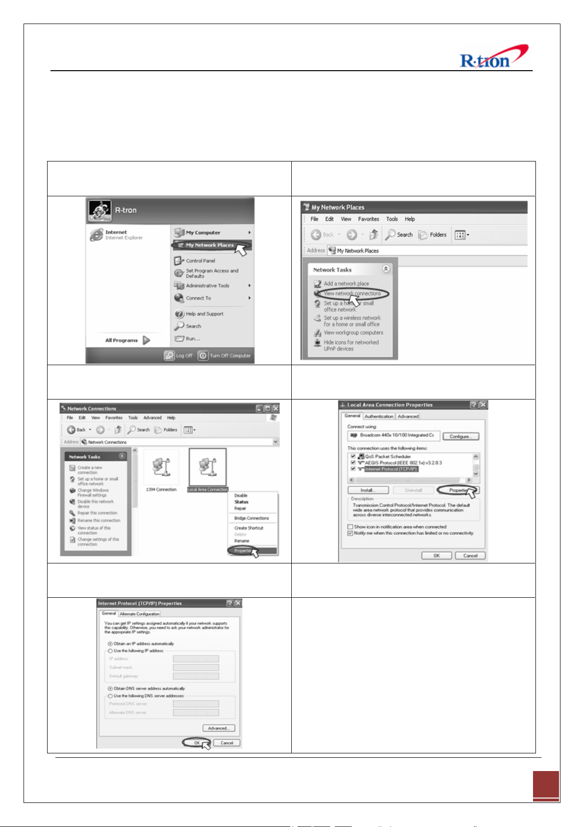
4.9.1.1 Window XP
Step 1: Click the Start button and select My
Network places.
Step 3: Right-click on the Local Area Connection
and select Properties to view the shortcut menu.
Step 2: Click View network connections.
Step 4: Select Internet Protocol (TCP/IP) and click
Properties.
Step 5: Check Obtain an IP address automatically
Step 6: Close all widows.
and click OK.
APEX730 USER MANUAL V1.0.00 Tech Support: 1-888-317-8766
30
Page 34

4.9.1.2 Windows Vista
Step 1: Click the Start button and select Control
panel.
Step 3: Click Network and Sharing Center. Step 4: Click View status of Local Area Connection.
Step 2: Click Network and Internet
Step 5: Click Properties and a caution pop-up
window will appear. Click OK.
Step 7: Check Obtain an IP address automatically
and Click OK.
Step 6: Select Internet Protocol Version 4 (TCP/IPv4)
and click Properties.
Step 8: Close all windows.
APEX730 USER MANUAL V1.0.00 Tech Support: 1-888-317-8766
31
Page 35

5. Troubleshooting
Before contacting your service dealer, refer to the following guidelines. If the APEX730 repeater
does not work normally after completing the following troubleshooting, please contact your
local dealer or R-tron America’s Tech support line (1-888-31R-TRON).
External alarm lamps on the front of the repeater indicate current condition. Green lamp
indicates power to the repeater, yellow indicates caution, and red indicates shut sown
5.1 LED Alarm
Problem Check Point Solution
Critical PWR LED is Flicking Power supply out of range
- Confirm AC 110 - 220V common use power
and power cable.
TD LED is red Tamper detected
- Front Cover open 상태인지 확인한다.
BTF LED is red Built-in test failure
- Web GUI alarm 상태를 통하여 아래 알람 중
어느 알람이 발생하였는 지 확인한다.
- UL Out-of-band emissions, DL Spurious
emissions, DL Interferer power exceeded, DL
Low isolation, Over temperature
- Case 2) When Alarm indicator 으로 문제 해결
RMF LED is red Replaceable module failure
- reset Repeater’s power
- Repeater’s alarm LED is still red,
Technical Support
OSC LED is red Oscillation detected
- Donor / Server ant. Isolation을 확인하여
Gain+15dB 이하인 경우 ant 위치 조정을 하여
Isolation을 확보한다.
SD LED is red Shutdown
- Web GUI를 이용하여 S/D reason을 확인한다.
- Manual HPA Off인 경우 다시 On 시킨다.
- Overpower S/D이 발생하고, Manual Gain 설
정 상태인 경우 Gain 설정을 적절하게 낮춘다.
- Overpower S/D이 발생하고, ALC 기능이On되
어 있는 경우 ALC Level을 1~3dB 낮게 설정
하고 장시간 모니터링한 후 이상이 없으면
확정한다. (본 증상은 Input Power 변화가 심
한 환경에서 발생할 수 있음)
Minor DCF LED is orange Donor Circuitry failure
- DL Donor Power too high
- 중계기 입력으로 들어오는 DL input Power를
확인한 후 중계기 허용치 이상일 경우 외부
Atten을 달거나 ant 위치를 조정하여 허용치
이내로 들어오게 한다.
DPL LED is orange Donor power too low
- DL Donor Power too low
- 중계기 입력으로 들어오는 DL input Power가
Contact
APEX730 USER MANUAL V1.0.00 Tech Support: 1-888-317-8766
32
Page 36

너무 낮은 경우이며, 입력을 높일 수 있게
ant 위치를 조정한다.
CCF LED is orange Coverage Circuitry failure
- UL Power at coverage high, DL VSWR
- DPL LED가 정상인 상태에서 CCF LED만 발
생한 경우 UL Gain을 줄인다. (ALC On 상태에
서는 Gain Offset 조정으로 줄일 수 있다.)
RE LED is orange Reset engaged
- Reset alarm
- 중계기가 reset 되는 중이므로 외부에서 절대
중계기 조작을 해서는 안된다.
AGC LED is Flicking AGC active
- AGC On시
- ALC On 상태로 동작되고 있음을 표시하며
알람 상황은 아님.
5.2 GUI Alarm
Problem Check Point Solution
General Tamper detected
Power supply out of range
Communication failure
Field replaceable module
failure
Reset alarm
Manual shutdown alarm
Heartbeat
장비의 조립 상태를 확인하고 front cover의 조
립 상태가 정상인지 확인한다.
- 입력 전원이 AC 110 - 220V 이내인지 확인
후 이상이 없으면
장비의 전원을 reset한 후에도 동일한 알람이
유지되면
장비의 전원을 reset한 후에도 동일한 알람이
유지되면
중계기가 reset 되는 중이므로 외부에서 절대
중계기 조작을 해서는 안된다.
설치 환경을 재 확인 후 이상이 없을 경우 해
당 HPA On 한다.
Remote NMS Cable 연결 상태를 확인한다.
Web GUI내 Heartbeat 주기를 확인한다.
Contact Technical Support
Contact Technical Support
Contact Technical Support
Uplink Oscillation detected
Power at coverage port too
high
Synthesizer failure
Hardware failure
Software failure
Out-of-band emissions out of
spec
Downlink Donor Power too high/low
Low isolation
Donor / Server ant. Isolation을 확인하여
Gain+15dB 이하인 경우 ant 위치 조정을 하여
Isolation을 확보한다.
UL Input Power가 너무 높은 경우이며,
Coverage ant 설치 환경을 다시 확인한다.
장비의 전원을 reset한 후에도 동일한 알람이
유지되면
장비의 전원을 reset한 후에도 동일한 알람이
유지되면
장비의 전원을 reset한 후에도 동일한 알람이
유지되면
타사 신호등 불요파 성분을 너무 높을 경우 발
생할 수 있으며, ant 위치 조정이 필요함.
DL Input Power를 확인하고, ant 위치 조정이
필요
Donor / Server ant. Isolation을 확인하여
Gain+15dB 이하인 경우 ant 위치 조정을 하여
Isolation을 확보한다.
Contact Technical Support
Contact Technical Support
Contact Technical Support
APEX730 USER MANUAL V1.0.00 Tech Support: 1-888-317-8766
33
Page 37

Synthesizer failure
Hardware failure
Software failure
Spurious emissions out of
spec
Interferer power exceeded
장비의 전원을 reset한 후에도 동일한 알람이
유지되면
장비의 전원을 reset한 후에도 동일한 알람이
유지되면
장비의 전원을 reset한 후에도 동일한 알람이
유지되면
타사 신호등 불요파 성분을 너무 높을 경우 발
생할 수 있으며, ant 위치 조정이 필요함.
타사 신호등 불요파 성분을 너무 높을 경우 발
생할 수 있으며, ant 위치 조정이 필요함.
Contact Technical Support
Contact Technical Support
Contact Technical Support
APEX730 USER MANUAL V1.0.00 Tech Support: 1-888-317-8766
34
Page 38

5.3 Communication Alarm
When you cannot login to the web GUI.
Solution
1. Click My Network places Æ View network
connections. Right-click on the Wireless
Network Connection and then click Disable.
2. Right-click on the Local Area Connection and then
click Disable. After clicking Disable, click Enable
again.
3. Double click the Local Area Connection and then
click the Support tab Æ Repair.
APEX730 USER MANUAL V1.0.00 Tech Support: 1-888-317-8766
35
Page 39

Solution
4. Open the Internet Browser, select Tools Æ
Internet Options.
Click Delete Files in the Temporary Internet files
section.
5. Click Start and select Run.
Type “ping 192.168.0.1-t” and click OK.
APEX730 USER MANUAL V1.0.00 Tech Support: 1-888-317-8766
36
Page 40
6. Specifications
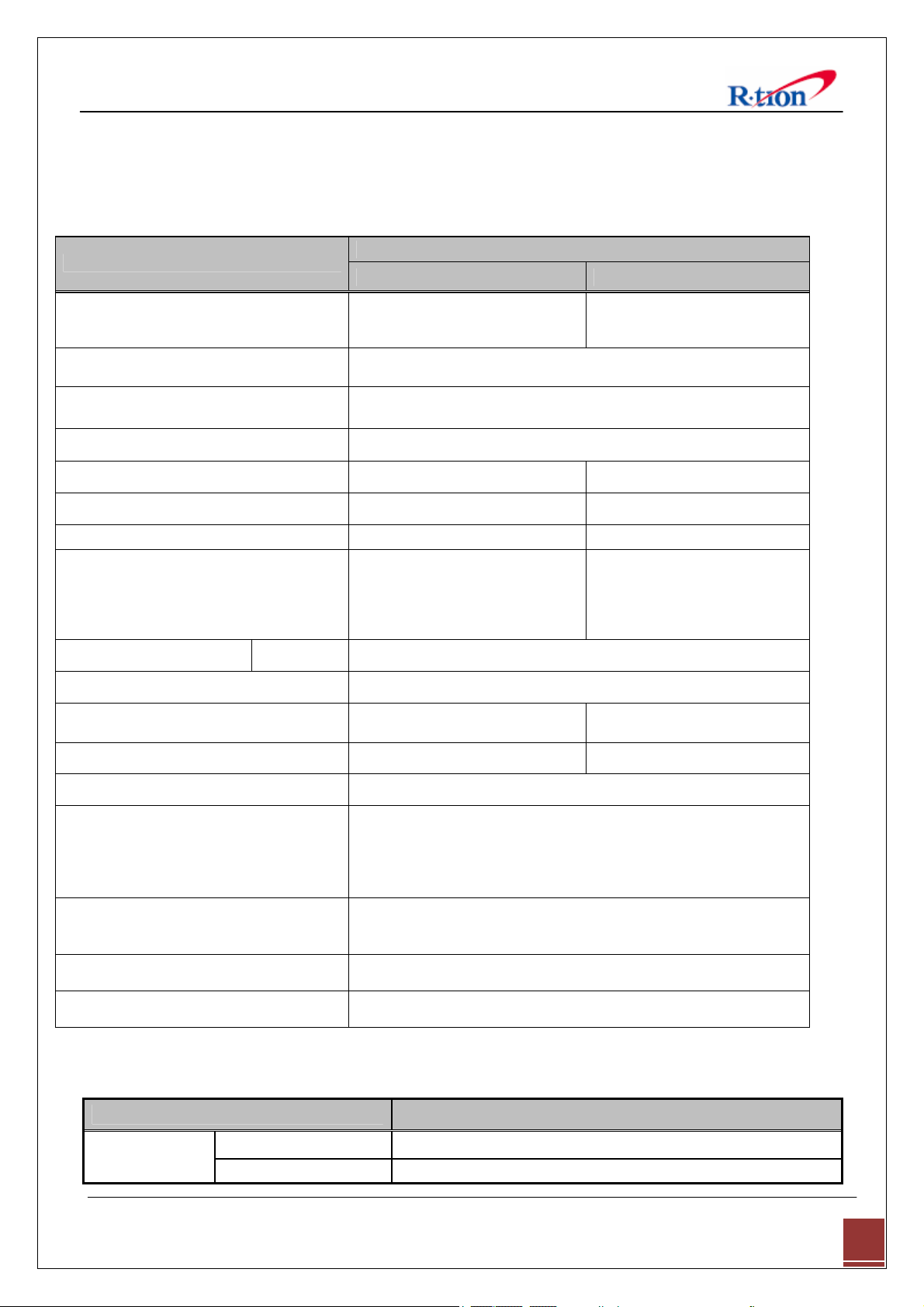
6.1 RF Characteristics
Parameter
Frequency Range
Channel Select Non-continuous A/B/C(Lower)/C(Upper) band Selectable.
Service LTE Service
Max. Composite Input Power -30dBm
Composite Output Power Range 30 dBm 30 dBm
Gain Range 60 - 90 dB 60 - 90 dB
Gain Offset recommend -2dB
EVM Compliance @carrier to
Waveform
ALC Range 30 dB
Gain Ripple ± 0.5-1 dB peak to peak
TX(Down-Link) RX(Up-Link)
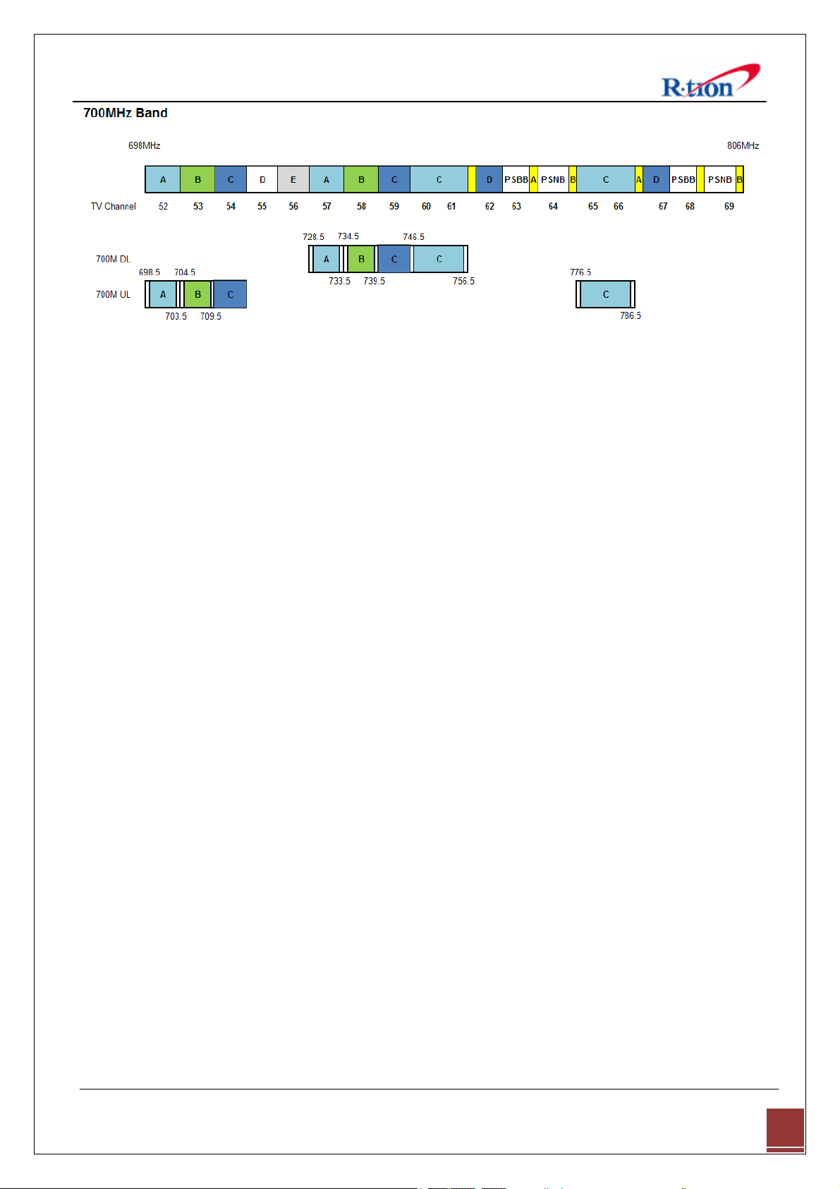
728~745 MHz (ABC block)
746 - 756 MHz (C block)
noise ratio 25dB
(max output, max gain, AGC
30dB)
700MHz Band
698~715 MHz (ABC block)
777 - 787 MHz (C block)
EVM Compliance @carrier to
noise ratio 20dB
(max output, max gain, AGC
30dB)
Noise Figure ≤ 5 dB ≤ 5 dB
EVM 8%-12.5% 12.5%-17.5%
Spurious Emission FCC role
-40dBm Input@1MHz from band edge (@MAX GAIN, MAX OUT
Inter-modulation (two tone)
Single Tone Input
Return Loss
Propagation Delay
-40dBm Input@2MHz from band edge (@MAX GAIN, MAX OUT
Output Power Variation<10dB / EVM 규격 변동 없을 것.
-40dBm Input@1MHz from band edge (@MAX GAIN, MAX OUT
Output Power Variation +2 to -4dBm / EVM 규격 변동 없을 것.
< 6 μs @ high roll-off performance(60 dBc)
< 3 μs @ normal roll-off performance(50 dBc)
6.2 Environmental Specification
Parameter
Environmental
Operating Temp
Humidity 20%~90%RH
PWR)
PWR)
PWR)
> 15dB
Specification
-10˚C~50˚C (14˚F~122˚F)
APEX730 USER MANUAL V1.0.00 Tech Support: 1-888-317-8766
37
Page 41

Cooling method Convection.
6.3 Electrical Specification
Parameter
AC Input
DC Output +24V/6.5A (150W)
Frequency
6.4 Mechanical Specification
Parameter Specifications Remark
RF connectors N-female x 2
Dimensions (WxHxD)
Weight
Specification
AC 110-220V
10.1 * 17.91 * 7.38 Inch
257 * 455 * 187.5 mm
37.04lbs
16.8 Kg max
60Hz
W * D * H
APEX730 USER MANUAL V1.0.00 Tech Support: 1-888-317-8766
38
Page 42

257mm
203.2mm
(8 inch)
152.4mm
(6 inch)
455mm
254mm
(10 inch)
7. Appendix
7.1 US LTE Channel
700M Band Down Link Up Link
No Block Channel Center Start Stop BW Center Start Stop BW
A 731.000
1
B 737.000
2
C(L) 743.000
4
C(U) 751.000
3
728.7425 733.2575 4.515
734.7425 739.2575 4.515
740.7425 745.2575 4.515
746.4925 755.5075 9.015
APEX730 USER MANUAL V1.0.00 Tech Support: 1-888-317-8766
701.000
707.000
713.000
782.000
698.7425 703.2575 4.515
704.7425 709.2575 4.515
710.7425 715.2575 4.515
777.4925 786.5075 9.015
39
Page 43
APEX730 USER MANUAL V1.0.00 Tech Support: 1-888-317-8766
40
Page 44

7.2 Warranty
LIMITED WARRANTY
This product, as supplied and distributed by R-tron, in the original carton, is warranted by R-tron against
manufacturing defects in materials and workmanship for a limited warranty period of:
Five (5) Year Parts and Labor
This limited warranty begins on the original date of purchase, and is valid only on products purchased
and used in the United States. R-tron will repair or replace this product, at our option and at no charge as
stipulated herein, with new or reconditioned parts or products if found to be defective during the limited
warranty period specified above. All replaced parts and products become the property of R-tron and must
be returned to R-tron. Replacement parts and products assume the remaining original warranty.
This limited warranty covers manufacturing defects in materials and workmanship encountered in normal,
and except to the extent otherwise expressly provided for in this statement, use of this product, and shall
not apply to the following, including, but not limited to: damage which occurs in installation; applications
and uses for which this product was not intended; altered product or serial numbers; cosmetic damage or
exterior finish; accidents, abuse, neglect, fire, water, lightning or other acts of nature; use of products,
equipment, systems, utilities, services, parts, supplies, accessories, applications, installations, repairs,
external wiring or connectors not supplied or authorized by R-tron which damage this product or result in
service problems; or incorrect electrical line voltage, fluctuations and surges; customer adjustments and
failure to follow operating instruction. R-tron does not warrant uninterrupted or error-free operation of
the product.
THERE ARE NO EXPRESS WARRANTIES OTHER THAN THOSE
LISTED AND DESCRIBED ABOVE, AND NO WARRANTIES
WHETHER EXPRESS OR IMPLIED, INCLUDING, BUT NOT LIMITED
TO, ANY IMPLIED WARRANTIES OF MERCHANTABILITY OR
FITNESS FOR A PARTICULAR PURPOSE, SHALL APPLY AFTER
THE EXPRESS WARRANTY PERIODS STATED ABOVE, AND NO
OTHER EXPRESS WARRANTY OR GUARANTY GIVEN BY ANY
PERSON, FIRM OR CORPORATION WITH RESPECT TO THIS
PRODUCT SHALL BE BINDING ON R-tron.
APEX730 USER MANUAL V1.0.00 Tech Support: 1-888-317-8766
41
Page 45

7.3 Return Material Authorization (RMA) Procedure
The return and exchange of products are not allowed without prior approval from R-tron America, Inc.
Please follow the exchange procedure below.
1. Call Tech Support for troubleshooting.
2. If the device has a hardware problem, R-tron will replace it if it is within warranty.
A RMA number will be issued for the return.
3. R-tron will ship the replacement unit with a return shipping label.
4. The customer must return the product using the original packaging, including all accessories
and/or parts.
APEX730 USER MANUAL V1.0.00 Tech Support: 1-888-317-8766
42
 Loading...