

Page 1
APEX1933
User’s Manual
Please read this manual before operating this product.
After you finish reading this manual, store it in a safe place for future reference.
Page 2

FCC NOTIFICATION
This equipment generates or uses radio frequency energy. Changes or modifications to this equipment
may cause harmful interference unless the modifications are expressly approved in the instruction manual.
The user could lose the authority to operate this equipment if an unauthorized change or modification is
made.
This is NOT a CONSUMER device. It is designed for installation by FCC LICENSEES and QUALIFIED
INSTALLERS. You MUST have an FCC LICENSE or express consent of an FCC Licensee to operate this
device. Unauthorized use may result in significant forfeiture penalties, including penalties in excess of
$100,000 for each continuing violation.
Regulatory Statements
This device complies with Part 15 of the FCC Rules. Operation is subject to the following two Conditions:
1. This device may not cause harmful interference.
2. This device must accept any interference received, including interference that may cause undesired
operation.
Note: This equipment has been tested and found to comply with the limits for a Class B digital device,
pursuant to Part 15 of the FCC Rules. These limits are designed to provide reasonable protection against
harmful interference when the equipment is operated in a commercial environment. This equipment
generates, uses, and can radiate radio frequency energy, and if it is not installed and used in accordance
with the instruction manual, it may cause harmful interference to radio communications. Operation of this
equipment in a residential area is likely to cause harmful interference, in which case the user will be
required to correct the interference at his own expense.
Modifications: Any modifications made to this device that are not approved by Sun Microsystems, Inc.
may void the authority granted to the user by the FCC to operate this equipment.
WARNING: Only authorized antennas and cables described in this manual are permitted to be used
with this device. Other antennas and cables are expressly forbidden to be used. Authorized
Antennas:
- YG-1900-12: Yagi Antenna
- ACPS-1900-8: Indoor Directional Patch Antenna
Page 3

TABLE OF CONTENTS
1. GENERAL........................................................................................................................................................... 1
1.1 N
OTICE............................................................................................................................................................................................. 1
AFETY PRECAUTIONS...................................................................................................................................................................2
1.2 S
ERSION HISTORY..........................................................................................................................................................................3
1.3 V
Manual Version History List
1.3.1
.................................................................................................................................................3
1.3.2 Firmware Version History List
1.3.3 WEB GUI Version History List
.............................................................................................................................................3
.............................................................................................................................................3
1.4 GLOSSARY .......................................................................................................................................................................................4
2. INTRODUCTION............................................................................................................................................... 5
2.1 APEX1933......................................................................................................................................................................................5
2.2 APEX1933
OMPONENTS..................................................................................................................................................................................6
2.3 C
APEX1933
2.3.1
KEY FEATURES..........................................................................................................................................................6
................................................................................................................................................................................6
2.4 DESCRIPTION...................................................................................................................................................................................7
2.4.1
Overview
...................................................................................................................................................................................7
2.4.2 INTERNAL CONFIGURATION........................................................................................................................................................8
RFU (Radio Frequency Unit)
2.4.3
2.4.4 Duplexer
...................................................................................................................................................................................9
2.4.5 PSU (Power Supply Unit)
2.4.6 NCU (Network Control Unit)
...............................................................................................................................................9
......................................................................................................................................................9
...............................................................................................................................................9
3. MECHANICAL INSTALLATION.................................................................................................................... 12
3.1 M
OUNTING.................................................................................................................................................................................... 12
4. CABLE INSTALLATION ................................................................................................................................ 14
4.1 C
ABLE CONNECTION................................................................................................................................................................... 14
OWER ON.................................................................................................................................................................................... 15
4.2 P
ROUNDING ................................................................................................................................................................................. 15
4.3 G
5. GUI OPERATION............................................................................................................................................. 16
5.1 GUI
5.2 I
OPERATION FLOW CHART ................................................................................................................................................. 16
NTERNET NETWORK SETUP ...................................................................................................................................................... 17
Windows 7 (Refer to 5.9 for other versions of Windows)
5.2.1
............................................................................................. 17
5.3 SYSTEM LOGIN............................................................................................................................................................................. 18
YSTEM SETUP............................................................................................................................................................................. 19
5.4 S
Page 4

5.4.1 Time Setting
........................................................................................................................................................................... 19
5.4.2 Network Setup
5.4.3 User Note
5.4.4 User Comment
....................................................................................................................................................................... 19
............................................................................................................................................................................... 21
...................................................................................................................................................................... 22
5.5 GUI SYSTEM CONTROL.............................................................................................................................................................. 23
YSTEM CONTROL .................................................................................................................................................................... 23
5.5.1 S
Operating Control
5.5.2
5.5.3 Alarm Control
5.5.4 Band Select
................................................................................................................................................................ 24
....................................................................................................................................................................... 26
............................................................................................................................................................................ 26
5.6 GUI SYSTEM SETUP.................................................................................................................................................................... 27
5.6.1
Easy Setup
............................................................................................................................................................................. 27
5.6.2 MANUAL GAIN SETTING .......................................................................................................................................................... 30
5.7 GUI
STATUS.................................................................................................................................................................................. 33
System
5.7.1
5.7.2 Operating
5.7.3 Alarm
..................................................................................................................................................................................... 33
............................................................................................................................................................................... 33
...................................................................................................................................................................................... 33
5.8 FILE UPDATE ................................................................................................................................................................................ 34
MCU Firmware Download
5.8.1
................................................................................................................................................ 34
5.8.2 Web GUI Download
............................................................................................................................................................. 36
5.9 ATTACHMENT............................................................................................................................................................................... 37
5.9.1 Internet Network Setting
...................................................................................................................................................... 37
6. TROUBLESHOOTING .................................................................................................................................... 40
6.1 LED
6.2 GUI
6.3 C
ALARM................................................................................................................................................................................. 40
ALARM.................................................................................................................................................................................. 41
OMMUNICATION ALARM.......................................................................................................................................................... 42
7. SPECIFICATIONS............................................................................................................................................44
7.1 RF
7.2 E
7.3 E
7.4 M
CHARACTERISTICS................................................................................................................................................................ 44
NVIRONMENTAL SPECIFICATION ............................................................................................................................................. 45
LECTRICAL SPECIFICATION...................................................................................................................................................... 45
ECHANICAL SPECIFICATION.................................................................................................................................................... 45
8. APPENDIX........................................................................................................................................................ 46
8.1 US
PCS CHANNEL....................................................................................................................................................................... 46
8.2 W
8.3 R
ARRANTY................................................................................................................................................................................... 47
ETURN MATERIAL AUTHORIZATION (RMA) PROCEDURE.................................................................................................. 47
Page 5

1. General
1.1 Notice
Trademark
R-tron is a registered trademark of R-tron Inc.
Other products and company names mentioned here in this manual might be trademarks or trade names
of their respective owners.
Copyright
Copyright © R-tron Inc. 2000-2014
All Rights Reserved
Any reproduction, distribution, or revisions of any or all portions of this manual is prohibited without
written permission from R-tron Inc.
Notice
This document describes the specifications, installation, and operation of the APEX1933 equipment.
Hardware and software mentioned in this document are subject to continuous development and
improvement. Consequently, there may be minor discrepancies between the information in the document,
performance, and design of the product.
Specifications, dimensions, and other statements mentioned in this document are subject to change
without notice.
Questions or Comments
Address: R-tron Inc. 6402 College Boulevard, Overland Park, KS 66211
Phone: +1-913-344-9977, 1-888-317-8766
Fax: +1-913-344-9988
e-mail: info@r-tronamerica.com
Website: www.rtronamerica.com
APEX1933 USER MANUAL V1.2 Tech Support: 1-888-317-8766
1
Page 6
1.2 Safety Precautions
Opening the APEX1933 equipment could result in electric shock and may cause severe injury.
Connect the equipment frame ground to the building ground.
Operating the APEX1933 with antennas in very close proximity facing each other can lead to
severe damage to the equipment.
RF Exposure Infomation
The antenna(s) must be installed in a fixed installation and provide a separation distance of 76
cm from all persons and must not be collocated with any other transmitters except in
accordance with FCC multi-tran
ACPS-1900-8 antenna.
For more information about RF exposure, please visit the FCC website at www.fcc.gov
This equipment is for indoor use only and enables the communication wiring to communicate
inside the building.
smitter product procedures for both YG-1900-12 antenna and
Antenna Requirements
ANTENNAS: please read your manufacturers antenna specifications before installation.
Your antenna will require a type "N" connection. The antenna, Coax., and fittings must be 50
ohms.
APEX1933 USER MANUAL V1.2 Tech Support: 1-888-317-8766
2
Page 7
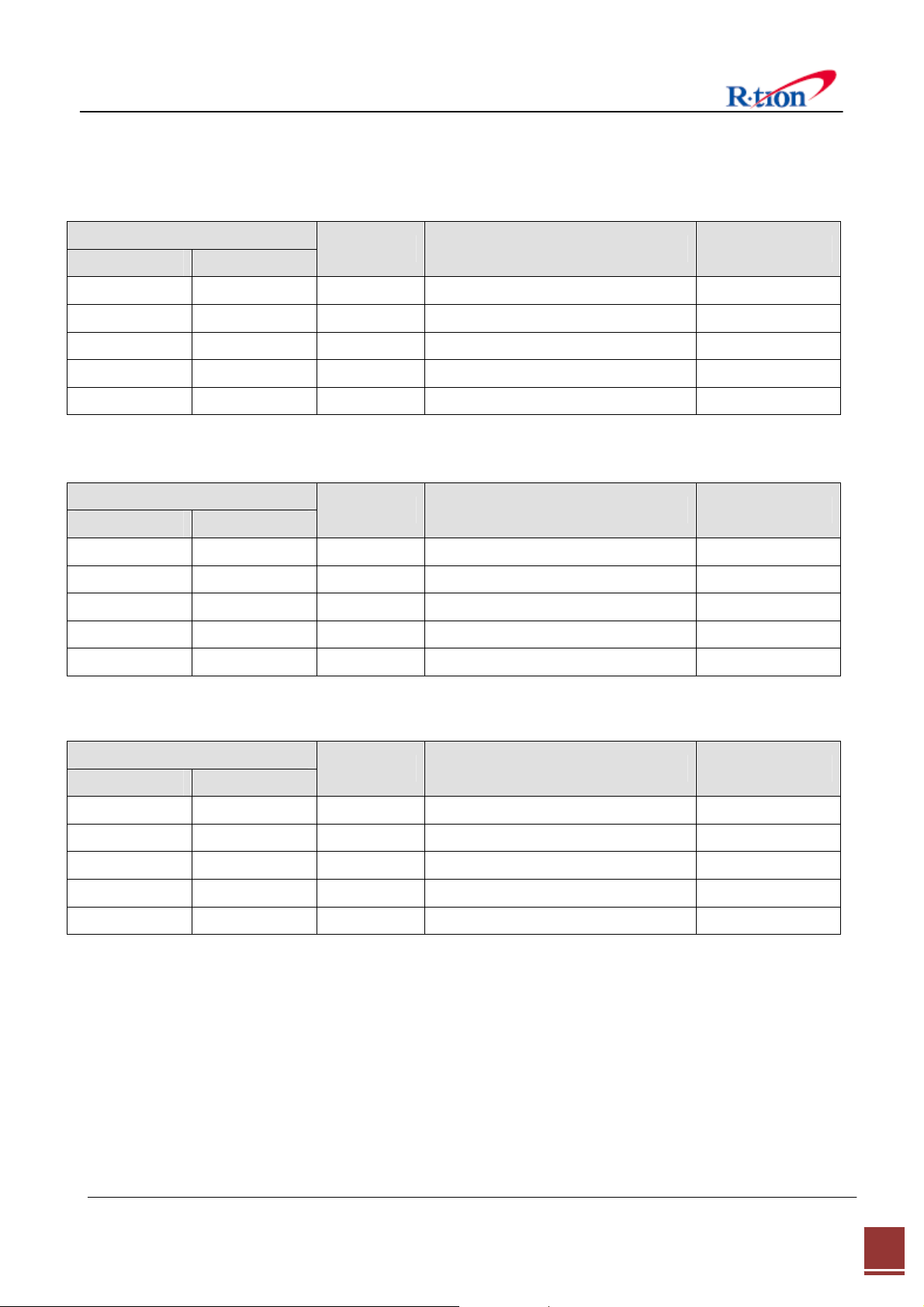
1.3 Version History
1.3.1 Manual Version History List
Revision Histor y
Approval Ver. Issue Ver.
V1.0 2013. 10. 18 Initial Version
V1.0 V1.1 2013. 10. 31 Component List Modification
V1.1 V1.2 2014. 01. 20 Key features Modification
Date Item/Description Reason
1.3.2 Firmware Version History List
Revision Histor y
Approval Ver. Issue Ver.
V1.0.00 V1.0.00 2013. 10. 18 Initial Version
Date Item/Description Reason
1.3.3 WEB GUI Version History List
Revision Histor y
Approval Ver. Issue Ver.
V1.3.00 V1.3.00 2013. 10. 18 APEX Series Common GUI
Date Item/Description Reason
APEX1933 USER MANUAL V1.2 Tech Support: 1-888-317-8766
3
Page 8
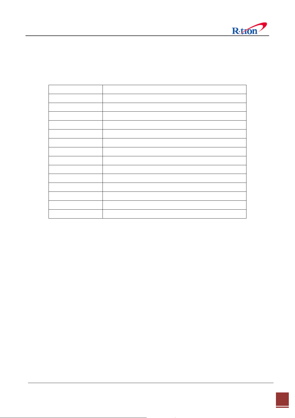
1.4 Glossary
The following is a list of abbreviations and terms used in this manual.
Abbreviation Definition
AC
CDMA Code Division Multiple Access
DC Direct Current
DL Downlink
GUI Graphic User Interface
LED Light Emitting Diode
PSU Power Supply Unit
RF Radio Frequency
UL Uplink
VSWR Voltage Standing Wave Ratio
NCU Network Control Unit
MCU Main Control Unit
NMS Network Management System
SNMP Simple Network Management Protocol
Alternating Current
AGC (Automatic Gain Control)
AGC prevents the equipment from exceeding its maximum output power by reducing the gain
automatically. AGC is used to adjust the gain to an appropriate level for a range of input signal
.
levels
ASD (Automatic Shutdown)
ASD helps protect the amplifier from over load. ASD helps protect the network by preventing
excessive signal output power.
ASD does not:
1. Prevent oscillation
2. Protect from excessive input.
There are three parameters: ASD Level, ASD Time, and ASD Iteration.
If the output power exceeds higher than the “ASD LEVEL”, the equipment will shut down for “ASD
TIME” seconds. If shutdown repeats “Iteration” times, the equipment will require manual re-start.
APEX1933 USER MANUAL V1.2 Tech Support: 1-888-317-8766
4
Page 9
2. Introduction
2.1 APEX1933
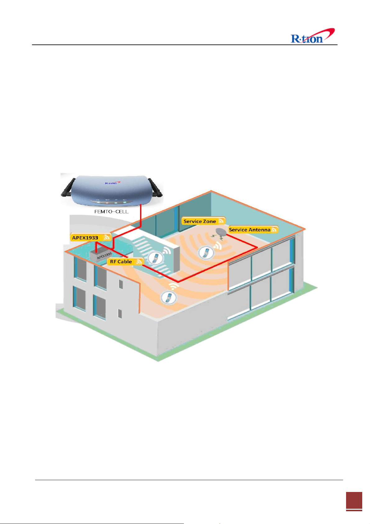
APEX1933 is used to fill out areas in APEX systems, such as base station fringe areas, business
and industrial building, etc.
APEX1933 receives signals from a Small Cell (Femto-Cell, Optional), amplifies and retransmits the
signals to the mobile stations. It also receives, amplifies and retransmits signals in the opposite
direction. Both directions are served simultaneously with the following features:
< Basic Organization >
Note :
Femto-cells will be one of the following products:
FCC ID:R4HAWEPPRO or FCC ID:QHYHUBBUBC4500-RT or FCC ID:QHYHUBBUBC4501-RT.
Femto-cells that are used with APEX 1933 must be connected to a wired uplink configuration. Both up
link and down link of the femtocell will be wired connections only when used with APEX 19
33.
APEX1933 USER MANUAL V1.2 Tech Support: 1-888-317-8766
5
Page 10
2.2 APEX1933 Key Features
◈ Design
- Digital filtering allows for customized channel selections.
- Digital filtering high quality, out of band rejection, and high performance
◈ User friendly design.
- Local monitoring and control through the Web GUI interface
- Remote monitoring and control through the Web GUI interface.
- Reports the status of connection as a function of SNMP regularly and reports an alarm if the
event occurred.
◈ Protection function
- Easy setup
- Isolation Check
- Auto Gain Control
- Auto Shutdown
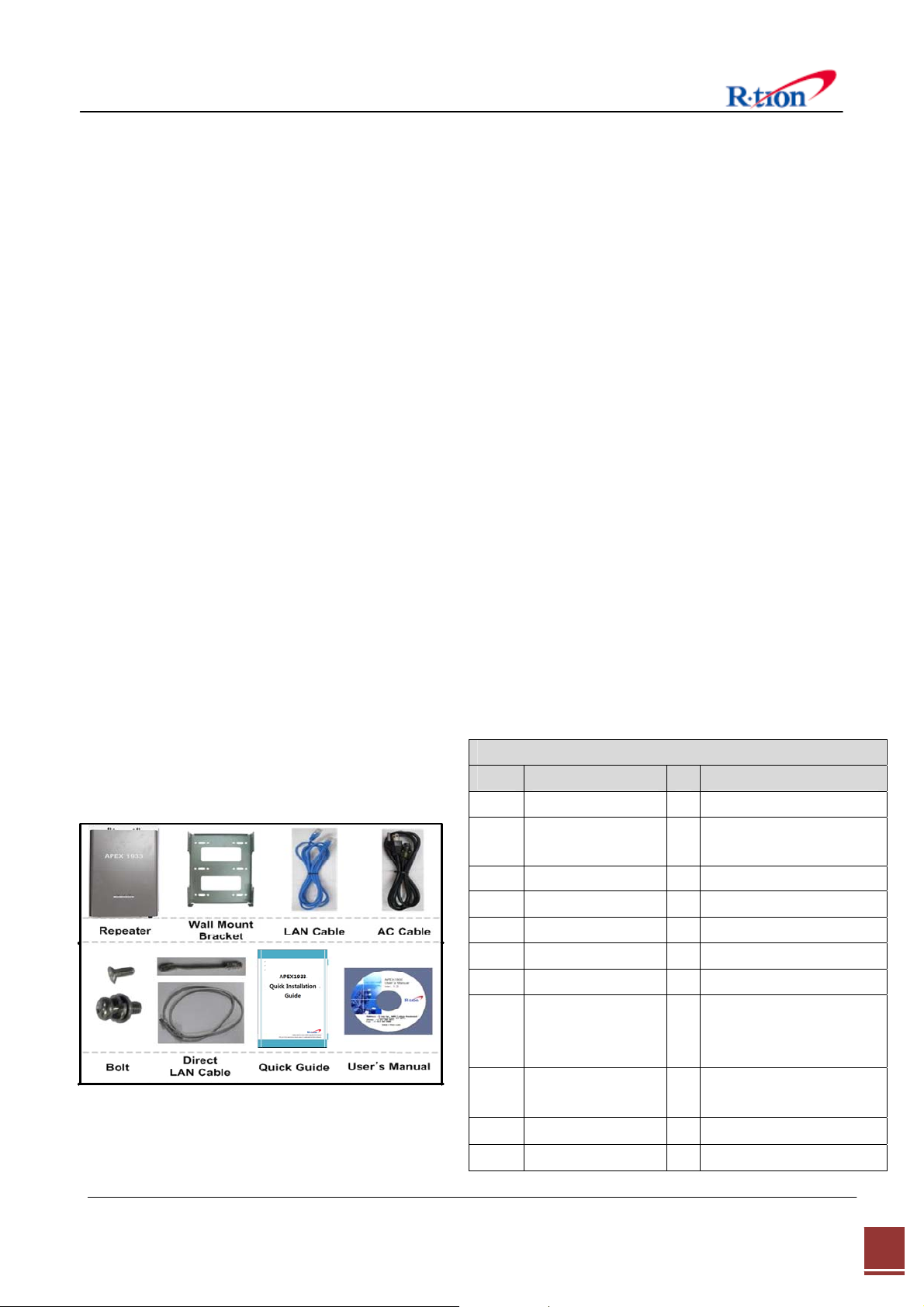
2.3 Components
2.3.1 APEX1933
APEX1924/1930/1933 Package
Index Items Q’ty Remark
1
2
3 Wall Mount Bracket 1
4
5
6
7
8
9
10
11
Equipment
NCU (Installed in
equipment)
LAN Cable
AC Cable
Bolt (M4*8mm)
Bolt (M6*16mm)
Direct LAN
Cable(120mm)
Direct LAN
Cable(1M)
Quick Guide
User’s Manual CD
1
1
1 Cross Type LAN Cable
1
2
4
1
1 Optional
1
1
For standalone
APEX PCS Series operation
Strait through LAN cable
for standalone APEX PCS
Series operation
APEX1933 USER MANUAL V1.2 Tech Support: 1-888-317-8766
6
Page 11
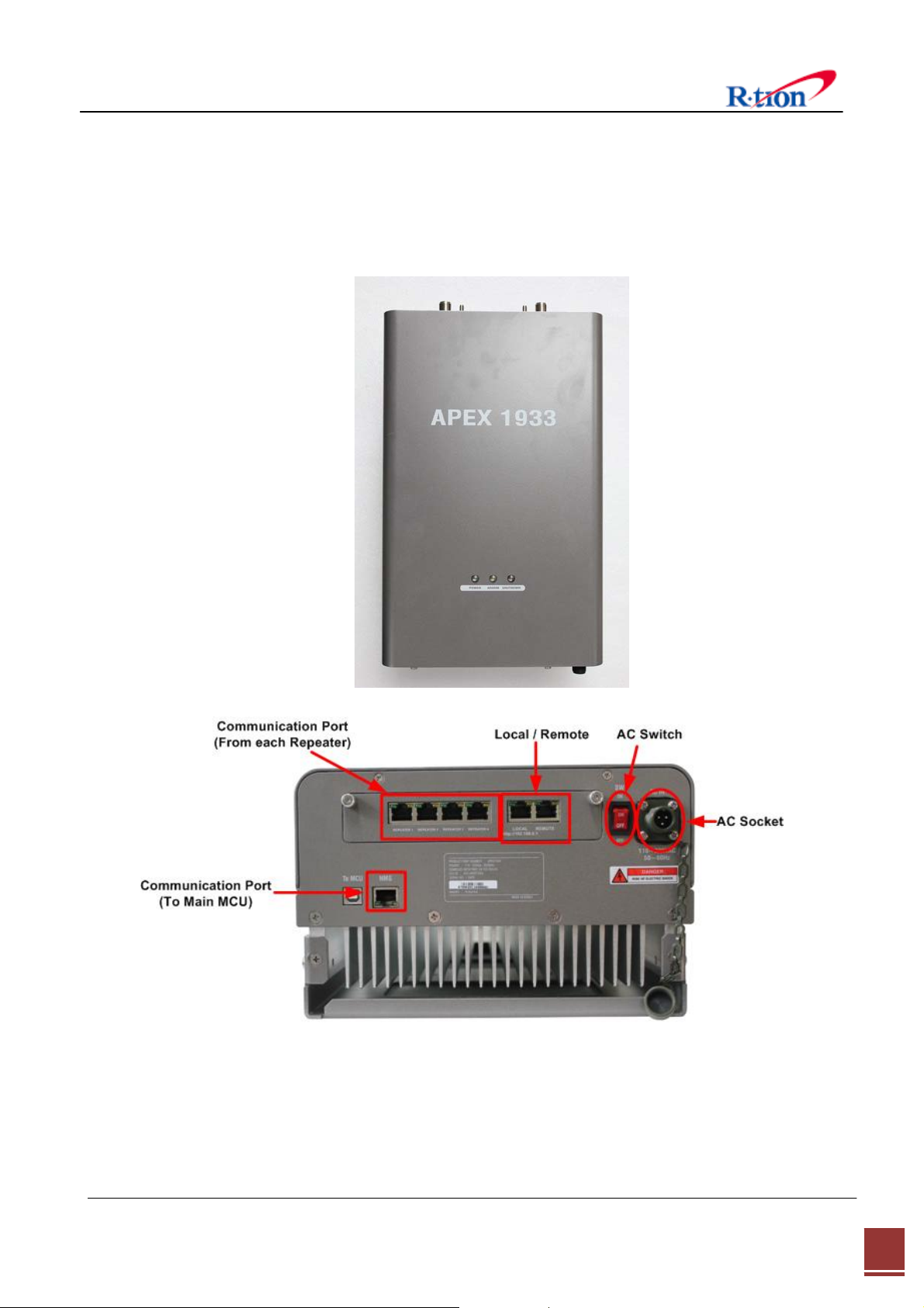
2.4 Description
2.4.1 Overview
No.2, 4 and 8 are for standalone APEX1924/1930/1933 operation.
APEX1933 USER MANUAL V1.2 Tech Support: 1-888-317-8766
7
Page 12
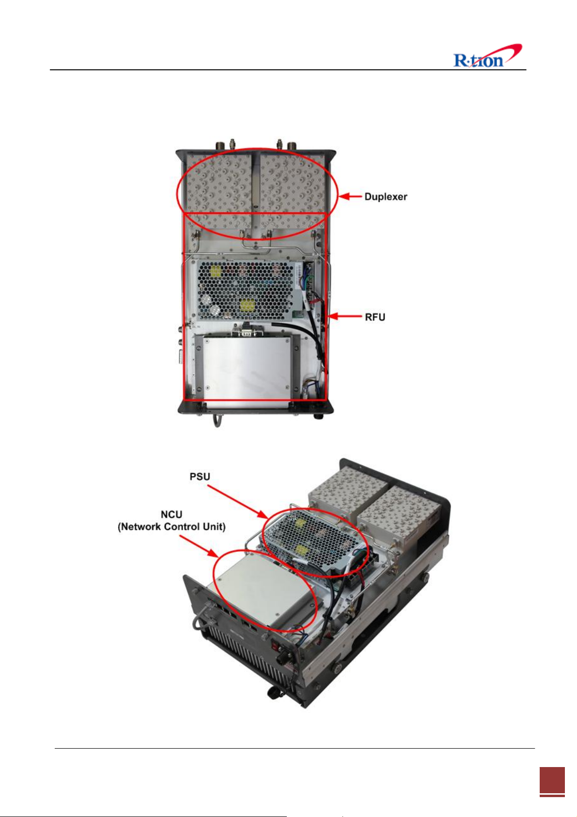
2.4.2 Internal Configuration
APEX1933 USER MANUAL V1.2 Tech Support: 1-888-317-8766
8
Page 13

2.4.3 RFU (Radio Frequency Unit)
The RFU (RF Unit) is a bi-directional amplifier that sharply filters out unwanted noise.
2.4.4 Duplexer
A duplexer is a device that combines two or more signals onto a common channel or
medium to increase its transmission efficiency.
2.4.5 PSU (Power Supply Unit)
The AC-DC adaptor supplies a steady DC power to the APEX19xx equipment by drawing
power from the general in-wall AC outlets.
2.4.6 NCU (Network Control Unit)
The NCU (Network Control Unit) is the control unit of the APEX19xx. The NCU controls and
monitors operational parameters, alarms, records event and performs many other functions.
2.4.7 ANTENNA REQUIREMENTS
ANTENNAS: please read your manufacturers antenna specifications before installation. Your
antenna will require a type “N” connection. The antenna, coax, and fittings must be 50
ohms impedance.
MAXIMUM ANTENNA SIZE CONNECTED TO THE APEX1933 REPEATER IS 12dBi,
The CDMA repeater requires antennas that operate in the desired frequency range of the
CDMA repeater. The APEX1933 Repeater has a frequency operating range of 1850 to 1915
MHz for the up- link, and 1930 to 1995 MHz for the downlink. Your antennas must operate
within these frequencies.
Failure to select the proper antennas will degrade the performance of your repeater.
2.4.8 ANTENNA ISOLATION & COAX CABLES
To protect wireless CDMA networks from interference caused by oscillation, the APEX1933
Repeater has internal automatic oscillation detection/control and auto shut down of the
repeater.
Improper installation practices could can initiate automatic shut-down of your repeater.
All repeaters require antenna isolation to prevent oscillation. The usable gain level of your
repeater is directly linked to the antenna isolation values. The maximum gain of your
repeater must be adjusted to a minimum of 10 dB lower than your antenna isolation values.
For example, if your antenna isolation value is 43 dB then your maximum usable repeater
gain is 33 dB.
APEX1933 USER MANUAL V1.2 Tech Support: 1-888-317-8766
9
Page 14

Due to the variations of system layouts and requirements it is not possible to have one
procedure that will suffice every installation. You are strongly advised to acquire the services
of an RF system designer to calculate your antenna isolation requirements.
Ensure that your antennas are at the maximum possible distance apart. Do not place
antennas in close proximity to each other; otherwise you will activate the oscillation
detection process.
Coax cables should be low loss 50 ohm, and suitable for 1850 to 1915 / 1930 to 1995 MHz
band frequency.
Antenna connections should be clean and moisture free. Do not spray lubricant into the
connectors as this prevents the signal traveling through the coax. Use a cleaning solvent
that has no oil and does not leave any residue. High quality oil-less contact cleaner is
suitable.
All coax connectors must be water tight and wrapped with water proof tape. Any moisture
in the connectors will degrade or eliminate the signals.
2.4.9 ANTENNA CONNECTIONS ON THE APEX1933
The APEX1933 can be installed indoors. If mounted indoors ensure there is no elevated
room temperatures and free flowing air for cooling of the repeater.
Connect the antenna that is aimed at the Cell Tower to the bottom left side N connector.
Connect the antenna that is aimed towards the Area Fill (target site) to the bottom right
side N connector.
Connect your Ethernet cable to the connector socket located on the left side of the power
on LED light.
NOTE; Water proof boot cover for the Ethernet connection, contact your Repeater supplier.
2.4.10
Additional protection is gained if the reverse link maximum power level is adjusted to
prevent the possibility of sudden unwanted high input RF levels. This can happen in various
ways, mobile cellular vehicle boosters coming within range of the cellular repeaters,
malfunctioning cellular phones, or other stray signals.
ADJUSTING REVERSE LINK MAXIMUM POWER LEVEL.
The APEX1933 has an adjustable Maximum allowable RF Power limit. The maximum
allowable RF power limit is 33dBm. The digitally controlled attenuator will not permit RF
signal levels greater than 33dBm.
The user can decrease the maximum allowable RF transmit power from 33 dBm to 0.0dBm.
The microprocessor controlled digital attenuator will maintain the preset allowable RF
transmit power limit regardless of unwanted high input signal levels.
APEX1933 USER MANUAL V1.2 Tech Support: 1-888-317-8766
10
Page 15

2.4.11 Calculating the Maximum Output Power allowed
The regulatory limits for maximum output power are specified in EIRP (equivalent isotro
pic radiated power). The EIRP level of a device will be installation dependent and final c
onfiguration is the responsiblity of the professional installer. However in general the fin
al EIRP can be calculated by adding the gain of the antenna used (specified in dBi) to
the output power available at the connector (specified in dBm) minus any cable loss.
APEX1933 USER MANUAL V1.2 Tech Support: 1-888-317-8766
11
Page 16
3. Mechanical Installation
The installation procedure is as follows:
• Confirm Items from List
• Mounting
• Grounding
• RF Cable Connection
• Power On
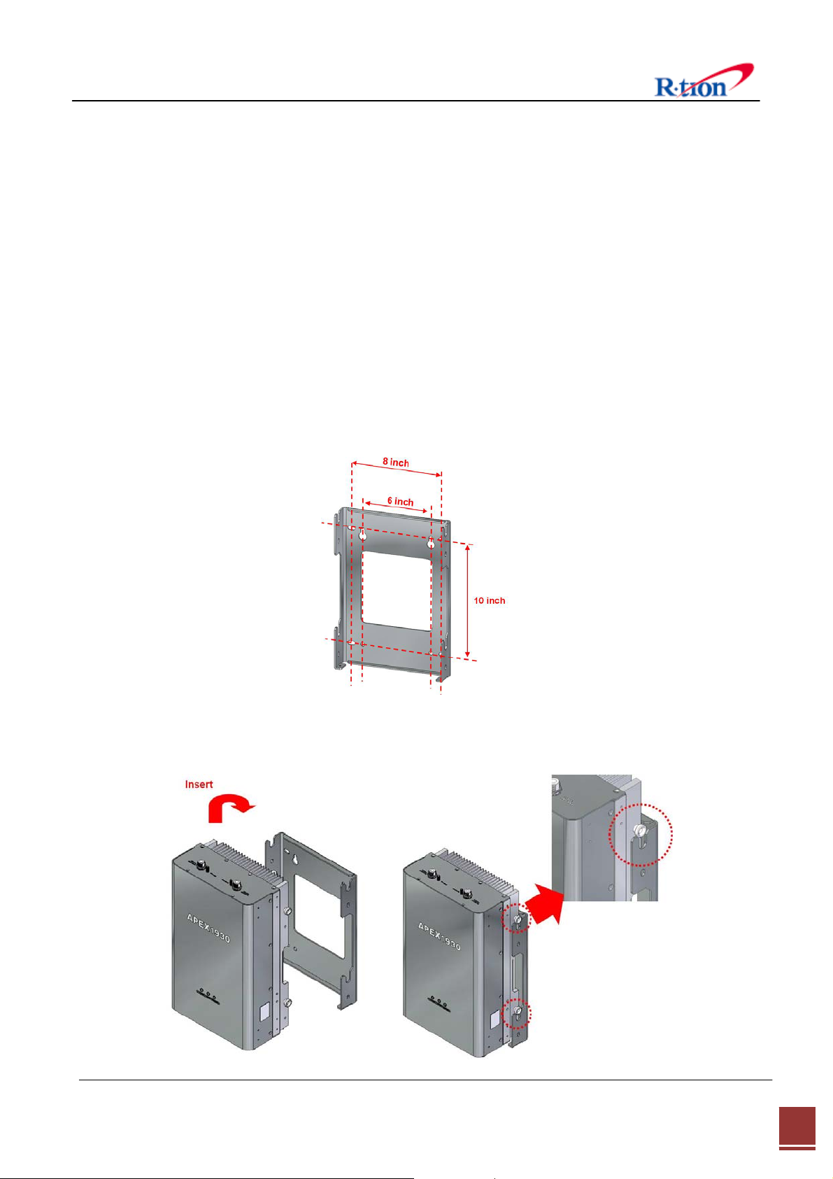
3.1 Mounting
Step 1 Drill holes directly through the template. Attach the mounting bracket to the wall using
provided bolts (16/5*50mm) or extra screws.
Step 2 Lean the APEX19xx to hang the topside of the Guide Ring on the mounting bracket, and
push toward the wall to mount.
APEX1933 USER MANUAL V1.2 Tech Support: 1-888-317-8766
12
Page 17

Step 3 Fix the equipment using the 4 bolts (M6*12mm) provided.
Step 4 Fix the equipment using the 2 bolts (M4*8mm) provided.
Step 5 Connecting multiple APEX equipments.
APEX1933 USER MANUAL V1.2 Tech Support: 1-888-317-8766
13
Page 18

4. Cable Installation
4.1 Cable Connection
Step 1: Connect a cable from the donor antenna to the Donor Antenna Port.
Step 2: Connect a cable from a equipment’s service antenna to the Sever Antenna Port.
APEX1933 USER MANUAL V1.2 Tech Support: 1-888-317-8766
14
Page 19

4.2 Power On
※ Notice: Antenna cables must be installed before connecting AC Power.
4.3 Grounding
Step 1: Connect the power cord to the Equipment
Step 2: Plug the power cord into a wall outlet.
Step 3: Turn the red power button on
Step 4: Check if the green LED at the Top turns on.
Step 1: A rod on the left side is intended for a
building ground.
Step 2: Connect the ground cable to the rod.
APEX1933 USER MANUAL V1.2 Tech Support: 1-888-317-8766
15
Page 20

5. GUI Operation
APEX19xx operates on a customer provided PC based platform with the following system
requirements:
• Windows® XP or Windows® Vista, Windows 7
• Internet Explorer 6.0(Recommended) or higher.
• 128 MB RAM or higher.
• Pentium Ⅲ processor or higher.
• RJ-45 Cable required.
5.1 GUI Operation Flow Chart
APEX1933 USER MANUAL V1.2 Tech Support: 1-888-317-8766
16
Page 21

5.2 Internet Network Setup
5.2.1 Windows 7 (Refer to 5.9 for other versions of Windows)
Step 1: Click the Start button and select Control
Panel.
Step 3: Click Network and Sharing Center. Step 4: Click View status of Local Area Connection.
Step 2: Click Network and Internet.
Step 5: Click Properties and a caution pop-up
window will appear. Click OK.
Step 6: Select Internet Protocol Version 4 (TCP/IPv4)
and click Properties.
APEX1933 USER MANUAL V1.2 Tech Support: 1-888-317-8766
17
Page 22

Step 7: Check Obtain an IP address automatically
Step 8: Close all windows.
and click OK.
5.3 System Login
For APEX19xx operation access, go to Web GUI and Log in.
Step 1: Open your Web browser and type http://192.168.0.1 into the URL address box.
Then press the Enter key.
Step 2: Confirm a User ID and type the password into the password box.
Type “operator” for the password and then click OK.
Step 3: The pop-up message for the login success will appear. Click OK.
Step 4: When the login process is complete, the initial screen will appear.
APEX1933 USER MANUAL V1.2 Tech Support: 1-888-317-8766
18
Page 23

5.4 System Setup
When you click Network in the initial screen you can set up User Note, Comment, Ethernet, and
time setting.
5.4.1 Time Setting
The time will automatically set to your PC time when you click OK.
In the above page, you can set system date and time and update time-related information.
5.4.2 Network Setup
<Network Setup>
APEX1933 USER MANUAL V1.2 Tech Support: 1-888-317-8766
19
Page 24

5.4.2.1 SYSTEM
• Cascade Code: Type the pre-assigned cascade code. Otherwise, you cannot access the
system setup.
¾ Set up for multiple bands
Equipment with NCU installed is designated as the master control. The other
equipments will connect to the master via RJ 45 cable.
The master web GUI will display the other equipments if the connection is successful.
1) Cascade code 1 of SYSTEM in Network setup:
Put Direct LAN Cable into Equipment 1 port and connect to NMS port.
2) For adding equipments refer to the RJ 45 cable connection below.
Input Cascade codes to the cascade code table under the SYSTEM section.
• Cascade Code Setting Chart
Equipment Equipment 1 Equipment 2 Equipment 3 Equipment 4
Cascade code Cascade Code 1 Cascade Code 2 Cascade Code 3 Cascade Code 4
APEX1933 USER MANUAL V1.2 Tech Support: 1-888-317-8766
20
Page 25

• Location Information: Enter the latitude and longitude. You can input values either in
Decimal Degrees or Degrees-Minutes-Seconds.
[Example]
(‘N/S’ | ‘E/W’) ddd.dddddd: (Latitude: N 39.006967 Longitude: W 94.532306)
• Refresh Time: Set each refresh time for connecting to Local port and Remote port.
5.4.2.2 ETHERNET SETTING
• Ethernet IP Mode/IP Address: Enables you to set a connection mode for the network
connected to the APEX19xx remote LAN port. When you “select” Auto, the device
automatically assigns the IP address. When you select “Static”, it is possible to set an
IP address of your choosing.
• SNMP: In order to send Heartbeat and alarm related information to a remote
monitoring server, you can set a server IP address. The factory default IP address is
10.22.25.15.
• Heartbeat Interval: Sets the time to transmit the Heartbeat to the NMC Server.
5.4.3 User Note
(Default value is 20 minutes.)
<User Note>
APEX1933 USER MANUAL V1.2 Tech Support: 1-888-317-8766
21
Page 26

• Location Information: Type the location information such as the building name, address, city,
state, zip code and telephone, and then click Apply.
• Donor Site Information: Type the base station’s ID, and then click Apply.
• Installer Information: Type the installer information such as the company, name and
telephone, Click Apply.
5.4.4 User Comment
<User Comment>
• User Comment: The user can store up to 50 comments in memory. The length of each
comment is limited to 20 characters.
APEX1933 USER MANUAL V1.2 Tech Support: 1-888-317-8766
22
Page 27

5.5 GUI System Control
5.5.1 System Control
APEX1933 USER MANUAL V1.2 Tech Support: 1-888-317-8766
23
Page 28

• Easy Setup is a fast start function. The function measures Isolation, detects input level and
assign gain to achieve maximum output power. The function ends with the equipment set
to amplify signals in both directions within the confines of the band selection. Before
running easy setup, set the center frequency and bandwidth (refer to 4.3.3 part 2).
Maximum DL output power requires at least -10dBm input power and sufficient antenna
isolation.
• Isolation Check can be executed at anytime to measure isolation between the donor and
server antennas. Isolation Check momentarily disables service. Isolation check automatically
runs when factory default is initiated.
• Factory Default restores the amplifier to its initial state. The function ends with amplifiers
off, AGC mode off, gain set to minimum(15dB) and UL gain offset set to 0dB. Band selection
and all other system parameters are not changed. The featurs is usefull in claering abnormal
conditions.
• System Reset cycles the microprocessor unit. The function is similar to switching off/on the
equipment power switch.
5.5.2 Operating Control
• DL and UL Path Control allows the user to toggle on or off the power amplifiers.
• DL and UL Gain is available when AGC mode is off. The user may enter gain values
manually. Manual gain control is an alternative to automatic gain control (AGC). Manual
gain is disabled (grayed out) when AGC mode is on. Gain cannot be controlled manually
above the available gain found on the status page. The system will not allow gain to be
increased such that maximum output power (33dBm) is exceeded.
APEX1933 USER MANUAL V1.2 Tech Support: 1-888-317-8766
24
Page 29

• Gain Tracking sets UL gain equal to DL gain. The feature helps maintain forward and
reverse link balance. The function control is grayed out when AGC mode is on.
• Automatic Gain Control :
- In contrast to manual gain control, automatic gain control (AGC) sets gain such that the
desired amplifier output level (33dBm) is automatically set.
- The user controls gain by adjusting the AGC level. The user may set the level from 0dBm to
33dBm. AGC can be used to control the signal level radiated from the server antennas.
- AGC may also be user to match the equipment to a DAS (distributed antenna system). AGC
level may be restricted by available gain and DL input power.
• UL Gain offset is used in conjunction with AGC to reduce the amount of amplification in
the reverse direction (uplink). In the cases UL offset is set to 0dB.
• Automatic Shutdown (ASD) :
- ASD temporarily shuts down the amplifier if the ASD level is exceeded. It is not necessary to
turn off ASD. ASD events are stored in the alarm history log. Repeated ASD events will
eventually shutdown the amplifier permanently and trigger the external shutdown lamp.
- ASD Level is set to 36dBm by default. It is not necessary to change the default level.
How to prevent saturation or over-modulation
1. Hardware function
Input : If this device detect an over input signal, input hardware ALC will automatically
activated over
power rating+2dB within 100ns to protect it and in case of over ALC range
turn to Thru-Path by activating a relay to prevent from occurring
saturation of AMP and Digital board.
Output : If this device detect an over output signal, output hardware ALC will
automatically activated over
power rating+2dB within 100ns to prevent from occurring over output power.
2. Software function to adjust the maximum power output and secure linear operation
AGC(Automatic Gain Control) : automatically control the output power not to exceed
over the set value.
ALC : activating in AGC off condition to prevent from occurring over-output power
-
APEX1933 USER MANUAL V1.2 Tech Support: 1-888-317-8766
25
Page 30

5.5.3 Alarm Control
• Alarm response time may be set between 0 and 5 minutes.
• Alarm Mask allows the user to customize the type of alarms sent to the SNMP server when
remote monitoring is in use.
5.5.4 Band Select
• Band select sets the digital filter to the center frequency and bandwidth of the local
service for which the equipment is intended to amplify. Likewise, all other signals outside of
the selected Center Frequency and Bandwidth are rejected.
• The user can select one, two three distinct sections within the PCS band. Each of the 1st,
2nd and 3rd filter blocks can be set to 1MHz to 20MHz of Bandwidth. Only the downlink
center frequency is set by the user. The uplink center frequency is automatically set in
accordance with the downlink frequencies.
• Filter Rejection allows the user to change the digital filter characteristics. Normal rejection
is used for CDMA and EVDO service.
• Frequency information is available as a reference for setting the center frequency and
band width (refer to section 7).
APEX1933 USER MANUAL V1.2 Tech Support: 1-888-317-8766
26
Page 31

5.6 GUI System Setup
5.6.1 Easy Setup
Step 1: Click Apply after setting Center Frequency and Band Width in use.
Step 2: Input AGC Level desired and click Apply.
1) AGC Level 33dBm 2) AGC Level 30dBm
Step 3: Easy Setup proceeds to:
• Data Initial execution
• Isolation Test exeduted
• Calculation of Available Maximum Gain by the isolation
• DL/UL Path On
• AGC On to obtain DL Output Power AGC Level or Maximum Gain 43dB
• ASD On
APEX1933 USER MANUAL V1.2 Tech Support: 1-888-317-8766
27
Page 32

• AGC Off
• Easy setup takes about 2minutes.
Click Execute button of Easy Setup
Step 4: Click OK.
1) AGC Level 33dBm
2) AGC Level 30dBm
Step 5: Setup will automatically begin. This process takes approximately 3minutes.
APEX1933 USER MANUAL V1.2 Tech Support: 1-888-317-8766
28
Page 33

Result 1: Constant Maximum DL Output Power 33dBm (AGC Level 33dBm)
If the DL input Power ≥ -10dBm
Result 2: Constant Maximum DL Output Power 30dBm (AGC Level 30dBm)
If the DL input Power ≥ -10dBm
APEX1933 USER MANUAL V1.2 Tech Support: 1-888-317-8766
29
Page 34

5.6.2 Manual Gain Setting
5.6.2.1 AGC mode “On” Setting
Step 1: Repeat Step 1 through Step 2
Step 2: Isolation Check
The Isolation will calculate the Available Maximum Gain which defines the maximum gain
to be setup.
Click Isolation
Step 3: Click OK.
Step 4: When below pop-up appears after Isolation is completed, click OK.
APEX1933 USER MANUAL V1.2 Tech Support: 1-888-317-8766
30
Page 35

Step 5: AGC must be turned on. AGC automatically assigns gain in accordance with AGC level.
Use AGC level to increase or decrease gain.
(Gain Offset is a gain differential between DL Output gain and UL output gain.)
Ex> AGC Level 33dBm, Gain Offset -3dB → DL Gain 43dB, UL Gain 40dB
AGC Level 33dBm, Gain Offset 0dB → DL Gain 43dB, UL Gain 43dB
Step 6: Tur n on t he DL and UL path controls.
APEX1933 USER MANUAL V1.2 Tech Support: 1-888-317-8766
31
Page 36

5.6.2.2 AGC mode “Off” setting
When you want to set gain value not using Auto Gain control refer to the following.
Step 1: For manual gain control AGC must be turned off.
Step 2: The user can select any gain value as long as it does over-drive the amplifier or exceed
isolation requirements. Gain is automatically limited where conditions do not permit high
gain. Select the DL and UL Gain values. Tur n on the DL and UL path controls.
APEX1933 USER MANUAL V1.2 Tech Support: 1-888-317-8766
32
Page 37

5.7 GUI Status
The status page display system, control, and alarm information.
When you set any value on the Control page the change will be reflected on Status page.
<Status>
5.7.1 System
• Firmware version and location are displayed under Equipment Information.
• The current band setting, set from the control page, is shown in bold font.
5.7.2 Operating
• DL Path Monitor displays input from the donor antenna circuit, output power at equipment
server antenna port, and downlink amplifier gain.
• UL Path Monitor displays input from the server antenna circuit, output power at equipment
donor port, and uplink amplifier gain.
• Isolation Status shows isolation value (dB) between the donor antenna and server antennas.
• Available gain allowed by isolation measurement. Available gain is derived from the
antenna isolation value plus 15dB. Full system gain (43dB) is available if the antenna
isolation value is at least 58dB.
5.7.3 Alarm
• If an alarm occurs, the alarm LED on the equipment will turn on.
APEX1933 USER MANUAL V1.2 Tech Support: 1-888-317-8766
33
Page 38

Alarms shown on the status page will have orange (alarm) or green (normal) background.
• Details for alarm events are displayed on the Alarm History page.
For corrective action please refer to 6. Troubleshooting section.
5.8 File Update
5.8.1 MCU Firmware Download
Step 1. For target, select “MCU“. Choose the correct target slot. If you are not sure, follow the
LAN cable from the equipment receiving the update to the host equipment. The LAN
port number on the host equipment is the slot number for the equipment receiving the
update. Use the browse button to locate the update file.
Step 2 MCU firmware file has a “.bin“ filename extension. Click Open.
APEX1933 USER MANUAL V1.2 Tech Support: 1-888-317-8766
34
Page 39

Step 3 Click Update.
Step 4 When File update message appears and updating completed, go to Log-in page.
Log-in and confirm the firmware version has been updated.
APEX1933 USER MANUAL V1.2 Tech Support: 1-888-317-8766
35
Page 40

5.8.2 Web GUI Download
Step 1 Select WEB in File Update page and click Browse.
Step 2 Select Firmware file which has “.web“ filename extension to download. Click Open.
Step 3 Click Update.
APEX1933 USER MANUAL V1.2 Tech Support: 1-888-317-8766
36
Page 41

Step 4 When File update message appears and updating completed, go to Log-in page.
5.9 Attachment
5.9.1 Internet Network Setting
5.9.1.1 Window XP
Step 1: Click the Start button and select My
Network places.
Step 3: Right-click on the Local Area Connection
Step 2: Click View network connections.
Step 4: Select Internet Protocol (TCP/IP) and click
and select Properties to view the shortcut menu.
Properties.
APEX1933 USER MANUAL V1.2 Tech Support: 1-888-317-8766
37
Page 42

Step 5: Check Obtain an IP address automatically
and click OK.
5.9.1.2 Windows Vista
Step 1: Click the Start button and select Control
panel.
Step 6: Close all widows.
Step 2: Click Network and Internet
Step 3: Click Network and Sharing Center. Step 4: Click View status of Local Area Connection.
APEX1933 USER MANUAL V1.2 Tech Support: 1-888-317-8766
38
Page 43

Step 5: Click Properties and a caution pop-up
Step 6: Select Internet Protocol Version 4 (TCP/IPv4)
window will appear. Click OK.
Step 7: Check Obtain an IP address automatically
and Click OK.
and click Properties.
Step 8: Close all windows.
APEX1933 USER MANUAL V1.2 Tech Support: 1-888-317-8766
39
Page 44

6. Troubleshooting
Before contacting your service dealer, refer to the following guidelines. If the APEX1933
equipment does not work normally after completing the following troubleshooting, please
contact your local dealer or R-tron America’s Tech support line (1-888-31R-TRON).
External alarm lamps on the front of the equipment indicate current condition. Green lamp
indicates power to the equipment, yellow indicates caution, and red indicates shut sown
6.1 LED Alarm
Problem Cause Solution
No LED on Power failure Check the power cord for secure connection
Mobile device has
poor performance.
Gain, Input/ Output
power or DC Current
are changing
randomly or appear
to be unstable.
Equipment service
Login to the web GUI.
Check the setting, alarm status and input/output
degraded or not available.
power status.
Most common cause for unstable gain and power is
feedback oscillation brought on by insufficient
antenna isolation.
Oscillation
1. Reduce equipment gain and/or AGC level.
2. Improve the field conditions that cause poor
antenna isolation.
Automatic shutdown occurs when the amplifier is
over driven. The amplifier is most commonly
overdriven by:
1. Oscillation due to poor antenna isolation.
2. High input power combined with high gain
settings including high UL input from the mobile
The red light is on. Automatic Shutdown
device.
User the alarm history page to determine the cause
of the shutdown. Eliminate the root cause of the
shutdown and restart the equipment.
Technical Support
Web site: www.r-tronamerica.com
Toll Free: 888-317-8766
APEX1933 USER MANUAL V1.2 Tech Support: 1-888-317-8766
40
Page 45

6.2 GUI Alarm
Problem Check Point Solution
General
Downlink
DC Current
Temperature
ASD Check Isolation and DL/UL Input power..
Heartbeat
DL Input Power
DL Output Power
DL Return Loss
If the same alarm occurs after reset Power, request
technical support.
Execute of System Reset (NCU) on Network Setup
page. If the same alarm occurs request technical
support.
Check the connection of the Remote NMS Cable.
Check the interval of Heartbeat on the WEB GUI
DL Input alarm can be the result of low signal level
from the donor antenna circuit.
Tune Femto output level and/or reduce line loss.
Check DL input Power.
If input power exceeds max input power install an
attenuator on the donor antenna feed line.
Return loss alarm is the result of o poorly matched
antenna circuit. The equipment is almost never the
reason for return loss issues. A good quality 50 ohm
load placed over the equipment server port or donor
port will extinguish the alarm and prove the alarm is
caused by some external antenna issue.
If the UL Input Power is too high, suspect excessive
Uplink UL Output Power
mobile TX power. Determine root cause of high
mobile TX power.
APEX1933 USER MANUAL V1.2 Tech Support: 1-888-317-8766
41
Page 46

6.3 Communication Alarm
When you cannot login to the web GUI.
Solution
1. Click My Network places Æ View network
connections. Right-click on the Wireless
Network Connection and then click Disable.
2. Right-click on the Local Area Connection and then
click Disable. After clicking Disable, click Enable
again.
3. Double click the Local Area Connection and then
click the Support tab Æ Repair.
APEX1933 USER MANUAL V1.2 Tech Support: 1-888-317-8766
42
Page 47

Solution
4. Open the Internet Browser, select Tools Æ
Internet Options.
Click Delete Files in the Temporary Internet files
section.
5. Click Start and select Run.
Type “ping 192.168.0.1-t” and click OK.
APEX1933 USER MANUAL V1.2 Tech Support: 1-888-317-8766
43
Page 48

7. Specifications
7.1 RF Characteristics
Electrical Specifications
Parameter TX (Down-Link) RX (Up-Link)
Frequency Range 1930 - 1995 MHz 1850 - 1915 MHz
Service CDMA2000 or LTE(FDD) Service
Channel Select
Nomal Input Power Range -10 ~ +15 dBm -68 ~ -40 dBm
Composite Output Power Range 0 ~ 33 dBm ~ -25 dBm
Gain Range 15 ~ 43 dB 15 ~ 43 dB
Range 28 dB
AGC
Time
Center frequency + BW (1M - 20MHz)
Non-continuous 3 channel
the AGC must track only slow variations
with time on the order of 100ms.
Gain Ripple ± 1.0 dB
Noise Figure
Roll-off
Propagation Delay 8 μs (max)
IMD
Frequency stability < 0.02 ppm < 0.02 ppm
Spurious Emission
VSWR 1.5 : 1 (max)
Impedance
Max Gain
Min Gain
885kHz
1.25MHz
1.98MHz
2.25MHz
4MHz
-
-
> 50dBc at ± 1 MHz from band edge
> 50dBc at ± 2 MHz from band edge
≤ -13dBm -
885kHz : -45dBc / 30kHz
1.25MHz : -45dBc / 30kHz
1.98MHz : -50dBc / 30kHz
2.25MHz : -13dBm / 1MHz
4MHz : -13dBm / 1MHz
5 dB (max)
12 dB (max)
-
-
-
-
-
50Ω
APEX1933 USER MANUAL V1.2 Tech Support: 1-888-317-8766
44
Page 49

7.2 Environmental Specification
Parameter
Operating Temp
Environmental
Humidity
Cooling method
7.3 Electrical Specification
Parameter
Voltage
Current
Frequency
7.4 Mechanical Specification
Parameter Specifications Remark
RF connectors N-female x 2
Specification
-10˚C~50˚C (14˚F~122˚F)
5% ~ 95%RH
Convection.
Specification
AC 85-264V
+24V/6.5A (150W)
50/60(47-63)Hz
Dimensions (WxHxD)
Weight 44.09 lb 20 Kg max
9.35 * 16.8 * 5.67 Inch
242 * 426 * 144 mm
W * D * H
APEX1933 USER MANUAL V1.2 Tech Support: 1-888-317-8766
45
Page 50

8. Appendix
8.1 US PCS Channel
APEX1933 USER MANUAL V1.2 Tech Support: 1-888-317-8766
46
Page 51

8.2 Warranty
LIMITED WARRANTY
This product, as supplied and distributed by R-tron, in the original carton, is warranted by R-tron against
manufacturing defects in materials and workmanship for a limited warranty period of:
Five (5) Year Parts and Labor
This limited warranty begins on the original date of purchase, and is valid only on products purchased
and used in the United States. R-tron will repair or replace this product, at our option and at no charge as
stipulated herein, with new or reconditioned parts or products if found to be defective during the limited
warranty period specified above. All replaced parts and products become the property of R-tron and must
be returned to R-tron. Replacement parts and products assume the remaining original warranty.
This limited warranty covers manufacturing defects in materials and workmanship encountered in normal,
and except to the extent otherwise expressly provided for in this statement, use of this product, and shall
not apply to the following, including, but not limited to: damage which occurs in installation; applications
and uses for which this product was not intended; altered product or serial numbers; cosmetic damage or
exterior finish; accidents, abuse, neglect, fire, water, lightning or other acts of nature; use of products,
equipment, systems, utilities, services, parts, supplies, accessories, applications, installations, repairs,
external wiring or connectors not supplied or authorized by R-tron which damage this product or result in
service problems; or incorrect electrical line voltage, fluctuations and surges; customer adjustments and
failure to follow operating instruction. R-tron does not warrant uninterrupted or error-free operation of
the product.
THERE ARE NO EXPRESS WARRANTIES OTHER THAN THOSE
LISTED AND DESCRIBED ABOVE, AND NO WARRANTIES
WHETHER EXPRESS OR IMPLIED, INCLUDING, BUT NOT LIMITED
TO, ANY IMPLIED WARRANTIES OF MERCHANTABILITY OR
FITNESS FOR A PARTICULAR PURPOSE, SHALL APPLY AFTER
THE EXPRESS WARRANTY PERIODS STATED ABOVE, AND NO
OTHER EXPRESS WARRANTY OR GUARANTY GIVEN BY ANY
PERSON, FIRM OR CORPORATION WITH RESPECT TO THIS
PRODUCT SHALL BE BINDING ON R-tron.
8.3 Return Material Authorization (RMA) Procedure
The return and exchange of products are not allowed without prior approval from R-tron America, Inc.
Please follow the exchange procedure below.
APEX1933 USER MANUAL V1.2 Tech Support: 1-888-317-8766
47
Page 52

1. Call Tech Support for troubleshooting.
2. If the device has hardware problem, R-tron will replace it if it is within warranty.
A RMA number will be issued for the return.
3. R-tron will ship the replacement unit with a return shipping label.
4. The customer must return the product using the original packaging, including all accessories
and/or parts.
APEX1933 USER MANUAL V1.2 Tech Support: 1-888-317-8766
48
 Loading...