

Page 1
APEX 1924
User’s Manual
Please read this manual before operating this product.
After you finish reading this manual, store it in a safe place for future reference.
Page 2

Notice
Trademark
R-tron is a registered trademark of R-tron Inc.
Other products and company names mentioned here in this manual might be trademarks or trade names
of their respective owners.
Copyright
Copyright © R-tron Inc. 2000-2010
All Rights Reserved
Any reproduction, distribution, or revisions of any or all portions of this manual is prohibited without
written permission from R-tron Inc.
Notice
This document describes the specifications, installation, and operation of the APEX 1900-24 repeater.
Hardware and software mentioned in this document are subject to continuous development and
improvement. Consequently, there may be minor discrepancies between the information in the document,
performance, and design of the product.
Specifications, dimensions, and other statements mentioned in this document are subject to change
without notice.
Questions or Comments
Address: R-tron Inc. 6402 College Boulevard, Overland Park, KS 66211
Phone: +1-913-344-9977, 1-888-317-8766
Fax: +1-913-344-9988
e-mail: info@r-tronamerica.com
Website: www.rtronamerica.com
Page 3
Safety Precautions
Opening the APEX 1900-24 equipment could result in electric shock and may cause severe injury.
Connect the equipment frame ground to the building ground.
Operating the APEX 1900-24 with antennas in very close proximity facing each other can lead to
severe damage to the repeater.
RF EXPOSURE INFORMATION
A minimum separation distance of 7.9 inches (20cm) must be maintained between the user and the
external antenna of the repeater to satisfy FCC RF exposure requirements. For more information
about RF exposure, please visit the FCC website at www.fcc.gov
This equipment is for indoor use only and enables the communication wiring to communicate inside
the building.
APEX 1900-24 USER MANUAL V1.0.00 Tech Support: 1-888-317-8766
1
Page 4
Manual Version History List
Revision History
Approval Ver. Issue Ver.
Date Item/Description Reason
Firmware Version History List
Revision History
Approval Ver. Issue Ver.
Date Item/Description Reason
WEB GUI Version History List
Revision History
Approval Ver. Issue Ver.
Date Item/Description Reason
APEX 1900-24 USER MANUAL V1.0.00 Tech Support: 1-888-317-8766
2
Page 5

Contents
Glossary ...............................................................................................................................................4
1. Introduction..................................................................................................................................4
2. Description....................................................................................................................................5
2.1 Main Unit Overview............................................................................................................ 5
2.2 Internal Configuration.......................................................................................................... 6
2.2.1 RFU (RF Unit)……………………………………………………………………………...7
2.2.2 Duplexer…………………………………………………………………………………….8
2.2.3 PSU (Power Supply Unit)…………………………………………………………………..8
2.2.4 MCU (Main Control Unit)………………………………………………………………….8
3. Hardware Installation ...................................................................................................................8
3.1 Check List of Items ............................................................................................................. 9
3.2 Mounting............................................................................................................................ 9
3.3 Grounding ........................................................................................................................ 12
3.4 Cable Connection.............................................................................................................. 12
3.5 Power On……………..…….....……………….…..…...…………………………………………13
4. Operation....................................................................................................................................14
4.1 System Requirements ........................................................................................................ 14
4.2 Network Setup .................................................................................................................. 14
4.2.1 Windows XP……………………………………………………………………………….14
4.2.2 Windows Vista……………………………………………………………………………..16
4.2.3 Windows 7…………………………………………………………………………………20
4.3 System Login.................................................................................................................... 24
4.3.1 Network……………………………………………………………………………………..28
4.3.2 Status……………………………………………………………………………………….28
4.3.3 Control……………………………………………………………………………………...28
4.3.4 File Update…………………………………………………………………………………29
4.3.5 Alarm History………………………………………………………………………………29
5. Troubleshooting ..........................................................................................................................30
6. Specifications...............................................................................................................................35
6.1 RF Characteristics.................................................................................................................. 35
6.2 Mechanical Specification........................................................................................................ 36
7. Appendix.....................................................................................................................................37
APEX 1900-24 USER MANUAL V1.0.00 Tech Support: 1-888-317-8766
3
Page 6

Glossary
The following is a list of abbreviations and terms used in this manual.
Abbreviation Definition
AC Alternating Current
ANT Antenna
ATT Attenuator / Attenuation
CDMA Code Division Multiple Access
DC Direct Current
DL Downlink
GND Grounding
GUI Graphic User Interface
LED Light Emitting Diode
PLL Phase-locked loop
PSU Power Supply Unit
RF Radio Frequency
RSSI Received Signal Strength Indication
TEMP Temperature
UL Uplink
VSWR Voltage Standing Wave Ratio
AGC (Automatic Gain Control)
AGC feature prevents the repeater from exceeding its maximum output power by reducing the gain
automatically. AGC is used to adjust the gain to an appropriate level for a range of input signal
levels
.
ASD (Automatic Shutdown)
ASD does not:
1. prevent oscillation
2. protect from excessive input.
ASD helps protect the amplifier from over load. ASD helps protect the network by preventing
excessive signal output power.
There are three parameters: ASD Level, ASD Time, and ASD Iteration.
If the output power exceeds higher than the “ASD LEVEL”, the repeater will shut down for “ASD
TIME” seconds and it will turn the amp back on to measure the output power again. If this repeats at
“Iteration” times, the repeater will shut down completely.
1. Introduction
APEX1900-24 is used to fill out areas in APEX1900-24 systems, such as base station fringe areas,
business and industrial building, etc.
APEX1900-24 receives signals from a base station, amplifies and retransmits the signals to the
mobile stations. It also receives, amplifies and retransmits signals in the opposite direction. Both
directions are served simultaneously with the following features:
APEX 1900-24 USER MANUAL V1.0.00 Tech Support: 1-888-317-8766
4
Page 7

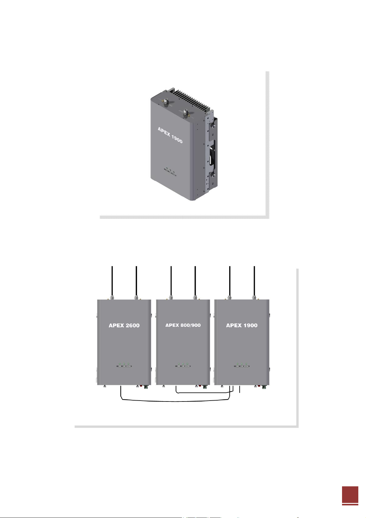
< Basic Organization >
APEX1924 Key Features
◈ Design(Each BDA is possible to service selected channels by the user within a band.)
- Possible to select any channel combination within a band caused by the Digital Filter.
- Using the Digital Filter: High quality, out of band rejection, high performance
◈ User friendly design.
- Local monitoring and control through the Web GUI interface
- Remote monitoring and control through the Remote Access and Control
- Reports the status of connection as a function of SNMP regularly and reports an alarm if the
event occurred.
◈ Protection function
- Isolation Check
- Auto Gain Control
- Auto Shutdown
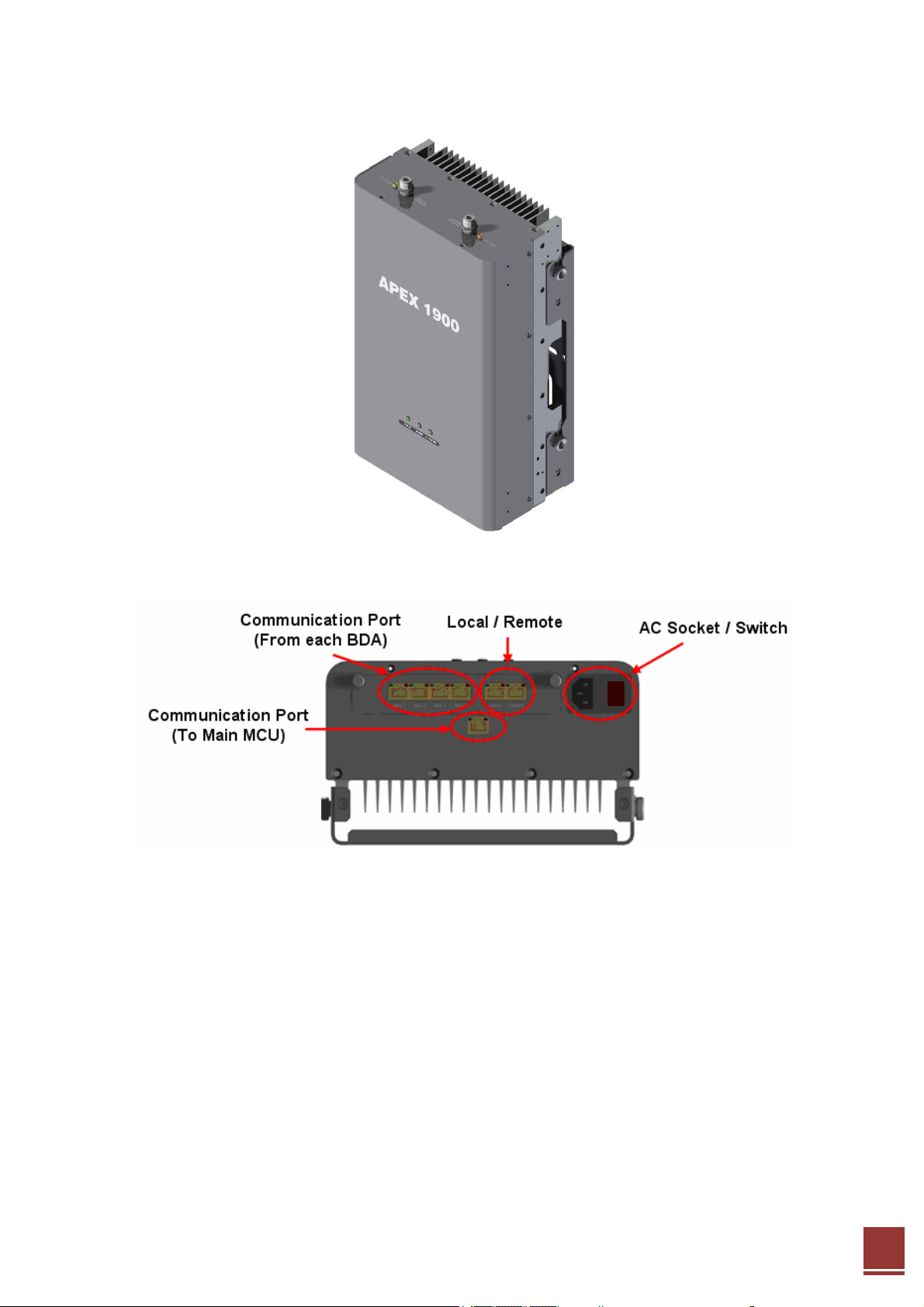
2. Description
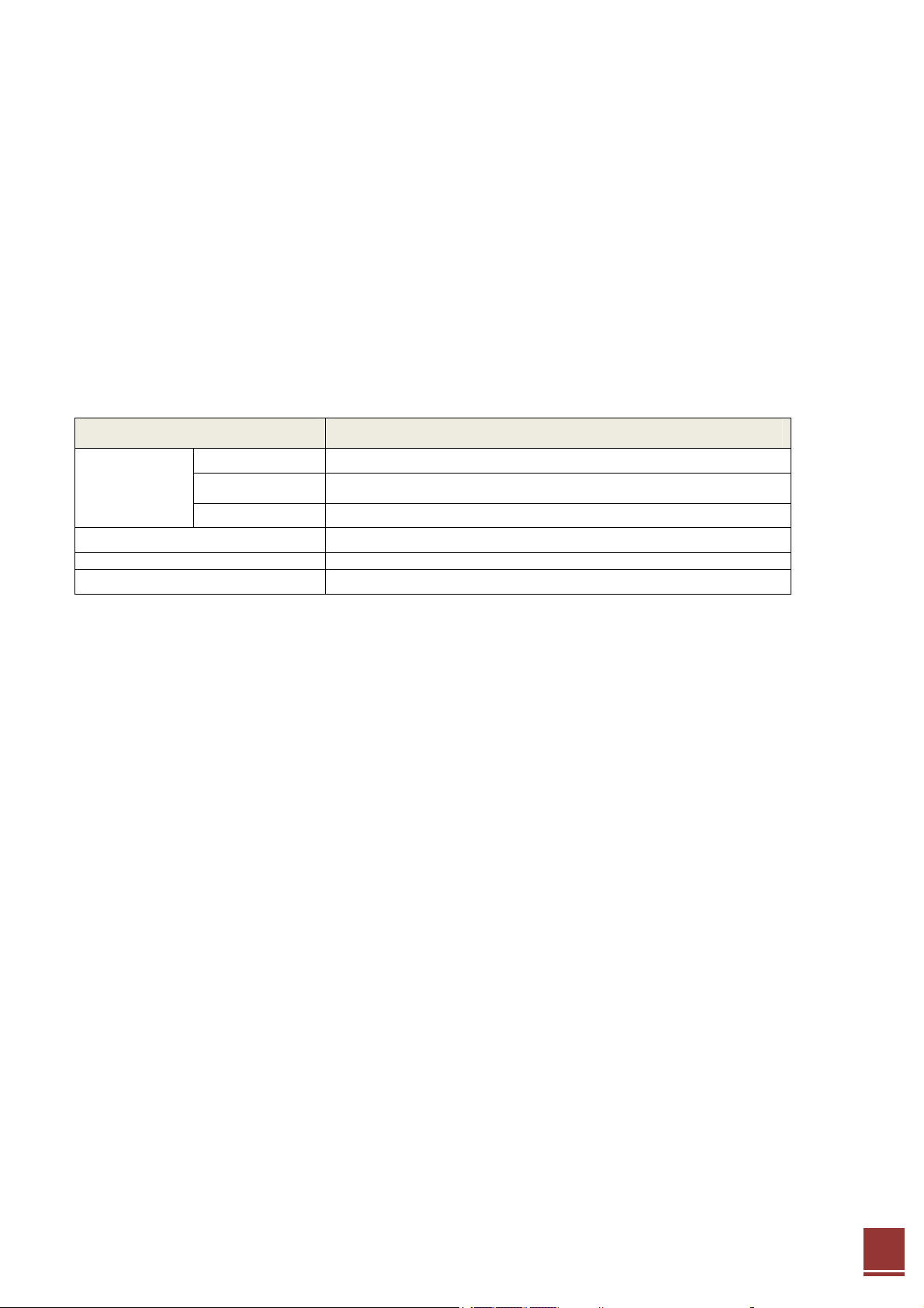
2.1 Main Unit Overview
APEX 1900-24 USER MANUAL V1.0.00 Tech Support: 1-888-317-8766
5
Page 8
2.2 Internal Configuration
APEX 1900-24 USER MANUAL V1.0.00 Tech Support: 1-888-317-8766
6
Page 9
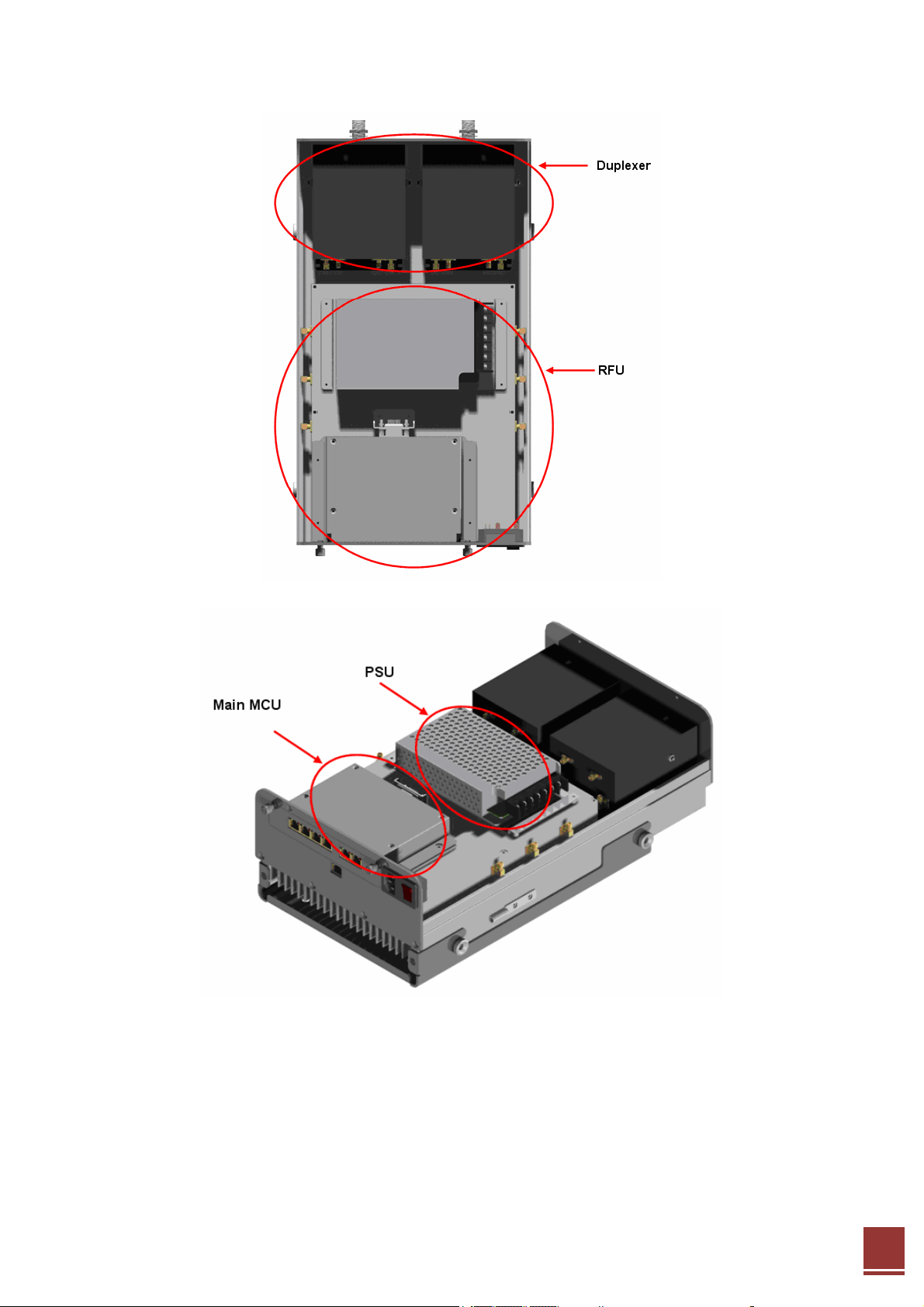
2.2.1 RFU (RF Unit)
The RFU (RF Unit) is a bi-directional amplifier that sharply filters out unwanted noise.
APEX 1900-24 USER MANUAL V1.0.00 Tech Support: 1-888-317-8766
7
Page 10
2.2.2 Duplexer
A duplexer is a device that combines two or more signals onto a common channel or
medium to increase its transmission efficiency.
2.2.3 PSU (Power Supply Unit)
The AC-DC adaptor supplies a steady DC power to the APEX1924 equipment by drawing
power from the general in-wall AC outlets.
Specification
Item Specification
Operating Temp
-10˚C~50˚C (14˚F~122˚F)
Environmental
Humidity 20%~90%RH
Cooling method Convection.
Vol ta ge
Current +24V/6.5A (150W)
Frequency
AC 85-264V
50/60(47-63)
2.2.4 MCU (Main Control Unit)
The MCU (Main Control Unit) is the control unit of a APEX1924. It controls and monitors
operational parameters. It is also responsible alarms, keeping event logs and performing
many other functions of the APEX1924.
3. Hardware Installation
The installation procedure is as follows:
• Confirm Items from List
APEX 1900-24 USER MANUAL V1.0.00 Tech Support: 1-888-317-8766
8
Page 11

• Mounting
• Grounding
• RF Cable Connection
• Power On
3.1 Check List of Items
Index Items Quantity
1 Repeater 1
2 AC Cable 1
3 LAN Cable 1
4 Anchor Bolt 4
5 Quick Installation Guide 1
6 User’s Manual 1
3.2 Mounting
Step 1: Drill holes directly through the template. and attach the mounting bracket to the wall
using provided bolts or extra screws.
APEX 1900-24 USER MANUAL V1.0.00 Tech Support: 1-888-317-8766
9
Page 12

Step 2: Lean the APEX1924 to hang the topside of the Guide Ring on the mounting bracket, and
push toward the wall to mount.
APEX 1900-24 USER MANUAL V1.0.00 Tech Support: 1-888-317-8766
10
Page 13
Step 3: Fix the APEX1924 using the 4 screws provided.
Step 4: Example
APEX 1900-24 USER MANUAL V1.0.00 Tech Support: 1-888-317-8766
11
Page 14

3.3 Grounding
A rod on the left side is intended for a building ground. Connect the ground cable to the rod.
3.4 Cable Connection
Step 1: Connect a cable from the donor antenna to the Donor Antenna Port.
Step 2: Connect a cable from a repeater’s service antenna to the Sever Antenna Port.
APEX 1900-24 USER MANUAL V1.0.00 Tech Support: 1-888-317-8766
12
Page 15

3.5 Power On
Step 1: Connect the power cord.
Step 2: Plug the power cord into a wall outlet.
Step 3: Check if the green LED at the Top turns on.
APEX 1900-24 USER MANUAL V1.0.00 Tech Support: 1-888-317-8766
13
Page 16

4. Operation
4.1 System Requirements
APEX1900-24 operates on a customer provided PC based platform with the following system
requirements:
• Windows® XP or Windows® Vista, Windows 7
• Internet Explorer 6.0(Recommended) or higher
• 128 MB RAM or higher
• Pentium Ⅲ processor or higher
• RJ-45 jack required
4.2 Network Setup
4.2.1 Windows XP
Step 1: Click the Start button and select My Network Places.
APEX 1900-24 USER MANUAL V1.0.00 Tech Support: 1-888-317-8766
14
Page 17

Step 2: Click View network connections.
Step 3: Right-click on the Local Area Connection and select Properties to view the shortcut
menu.
Step 4: Select Internet Protocol (TCP/IP) and click Properties.
APEX 1900-24 USER MANUAL V1.0.00 Tech Support: 1-888-317-8766
15
Page 18

Step 5: Check Obtain an IP address automatically and click OK.
Step 6: Close all widows.
4.2.2 Windows Vista
Step 1: Click the Start button and select Control Panel.
APEX 1900-24 USER MANUAL V1.0.00 Tech Support: 1-888-317-8766
16
Page 19

Step 2: Click Network and Internet.
Step 3: Click Network and Sharing Center.
APEX 1900-24 USER MANUAL V1.0.00 Tech Support: 1-888-317-8766
17
Page 20

Step 4: Click View status of Local Area Connection.
Step 5: Click Properties and a caution pop-up window will appear. Click OK.
APEX 1900-24 USER MANUAL V1.0.00 Tech Support: 1-888-317-8766
18
Page 21

Step 6: Select Internet Protocol Version 4 (TCP/IPv4) and click Properties.
Step 7: Check Obtain an IP address automatically and click OK.
Step 8: Close all windows.
APEX 1900-24 USER MANUAL V1.0.00 Tech Support: 1-888-317-8766
19
Page 22

4.2.3 Windows 7
Step 1: Click the Start button and select Control Panel.
Step 2: Click Network and Internet.
APEX 1900-24 USER MANUAL V1.0.00 Tech Support: 1-888-317-8766
20
Page 23

Step 3: Click Network and Sharing Center.
Step 4: Click View status of Local Area Connection.
APEX 1900-24 USER MANUAL V1.0.00 Tech Support: 1-888-317-8766
21
Page 24

Step 5: Click Properties and a caution pop-up window will appear. Click OK.
Step 6: Select Internet Protocol Version 4 (TCP/IPv4) and click Properties.
APEX 1900-24 USER MANUAL V1.0.00 Tech Support: 1-888-317-8766
22
Page 25

Step 7: Check Obtain an IP address automatically and click OK.
Step 8: Close all windows.
APEX 1900-24 USER MANUAL V1.0.00 Tech Support: 1-888-317-8766
23
Page 26

4.3 System Login
Step 1 Open your Web browser and type http://192.168.0.1 into the URL address box.
Then press the Enter key.
Step 2 The login screen will appear. Type “operator” for the ID and “rtron” for the password
and then Click OK.
Step 3 The pop-up message for the login success will appear. Click OK.
Step 4 When the login process is complete, the initial screen will appear.
APEX 1900-24 USER MANUAL V1.0.00 Tech Support: 1-888-317-8766
24
Page 27

4.3.1 Network
① Clock
<Network Clock Status and Set-up>
In the above page, you can set device time and update time-related information.
Click the “set time” button to save your settings.
② Network Set-up
<Network Set-up>
¾ SYSTEM
APEX 1900-24 USER MANUAL V1.0.00 Tech Support: 1-888-317-8766
25
Page 28

• Cascade Code: Type the pre-assigned cascade code. Otherwise, you cannot access the
system setup.
• Location Information: Enter the latitude and longitude. You can input values either in
Decimal Degrees or Degrees-Minutes-Seconds.
[Example]
(‘N/S’ | ‘E/W’) ddd.dddddd: (Latitude: N 39.006967 Longitude: W 94.532306)
• Product Information: This is for manufacturer use only. Do not change this value.
¾ ETHERNET SETTING
• IP Mode/IP Address: Enables you to set a connection mode for the network
connected to the CAT5DAS-RU port. When you “select” Auto, the device automatically
assigns the IP address. When you select “Static”, it is possible to set an IP address of
your choosing.
• SNMP: In order to send Heartbeat and alarm related information to a remote
• Heartbeat Interval: Sets the time to transmit the Heartbeat to the NMC Server.
③ User Note
monitoring server, you can set a server IP address. The factory default IP address is
10.22.25.15.
(Default value is 20 minutes.)
<Network User Note set-up>
APEX 1900-24 USER MANUAL V1.0.00 Tech Support: 1-888-317-8766
26
Page 29

• Location Information: Type the location information such as the building name, address, city,
state, zip code and telephone, and then click Apply.
• Donor Site Information: Type the base station’s ID, and then click Apply.
• Installer Information: Type the installer information such as the company, name and
telephone, Click Apply.
④ User Comment
<Network User Comment set-up>
• User Comment: You can store up to 50 comments in memory. The length of each comment
is limited to 20 characters.
APEX 1900-24 USER MANUAL V1.0.00 Tech Support: 1-888-317-8766
27
Page 30

4.3.2 Status
4.3.3 Control
<Status>
<Control>
APEX 1900-24 USER MANUAL V1.0.00 Tech Support: 1-888-317-8766
28
Page 31

4.3.4 File Update
4.3.5 Alarm History
Alarm history page allows you to record alarm information of each unit. Up to 300 lists can be
accommodated.
<Alarm History>
APEX 1900-24 USER MANUAL V1.0.00 Tech Support: 1-888-317-8766
29
Page 32

5. Troubleshooting
Before contacting your service dealer, please make sure you refer to the following guidelines. If
the APEX1900-24 repeater does not work normally after completing the following
troubleshooting, please contact your local dealer or R-tron America’s Tech support line (1-888-
31R-TRON).
The alarm information is displayed by the LED lights on the APEX1900-24 repeater.
Problem Cause Solution
No LED on Check the power cord for secure connection
The mobile phone is
not working well.
1. Gain, Input/ Output
power or DC Current
are changed randomly
under operating of DL
ALC, UL ALC and ASD.
2. Over isolation
attenuation range.
The red light
Turns on.
Oscillation
Check if the power is ON.
Check if the DL Amplifier and the UL Amplifier
of parameter Status are displayed as “ON”
a. Turn off the repeater.
b. Measure the isolation and verify if the
isolation between the donor antenna and the
service antenna is enough for the repeater.
Refer to the note on page 19.
If the measured isolation value is greater than
the required isolation value, turn Power On.
Check if DL Input Power, DL Output Power, UL
Output Power, Temperature, DC Voltage, DC
Current is out of range.
Especially, if the Input Power or Output Power
is out of range, please contact.
Technical Support
Web site: www.r-tronamerica.com
Toll Free: 888-317-8766
APEX 1900-24 USER MANUAL V1.0.00 Tech Support: 1-888-317-8766
30
Page 33

Problem Cause Solution
Cannot communicate
with the CAT-5 DAS
1. Click My Network places Æ View network
connections. Right-click on the Wireless Network
Connection and then click Disable.
APEX 1900-24 USER MANUAL V1.0.00 Tech Support: 1-888-317-8766
31
Page 34

Problem Cause Solution
2. Right-click on the Local Area Connection and
then click Disable. After clicking Disable, click
Enable again.
3. Double click the Local Area Connection and
then click the Support tab Æ Repair.
APEX 1900-24 USER MANUAL V1.0.00 Tech Support: 1-888-317-8766
32
Page 35

Problem Cause solution
4. Open the Internet Browser and then select
Tools Æ Internet Options.
Click Delete Files button in the Temporary
Internet files section.
APEX 1900-24 USER MANUAL V1.0.00 Tech Support: 1-888-317-8766
33
Page 36

Problem Cause Solution
5. Click Start and select Run.
Type “ping 192.168.0.1-t” and click OK.
APEX 1900-24 USER MANUAL V1.0.00 Tech Support: 1-888-317-8766
34
Page 37

6. Specifications
6.1 RF Characteristics
Parameter Down-Link Up-Link
Electrical Specifications
Frequency Range
Service CDMA2000 or LTE(FDD) Service
Channel Select
Input Power Range -71 – -31 dBm -71 – -31 dBm
Composite Output Power Range 24 dBm 24 dBm
Gain Range 55 - 95 dB 55 - 95 dB
Range 40 dB (min)
AGC
Time
Gain Ripple ± 1.5 dB
Max Gain 5 dB (max) 5 dB (max)
Noise Figure
Min Gain
Filter set 1
Roll-off
Filter set 2
1930 - 1995 MHz
(65M B.W)
Center frequency + BW (1M - 20MHz)
Non-continuous 3 channel
the AGC must track only slow variations
with time on the order of 100ms.
-
> 50dBc at ± 1 MHz from band edge
> 50dBc at ± 2 MHz from band edge
> 65dBc at ± 0.5 MHz from band edge
> 65dBc at ± 2 MHz from band edge
1850 - 1915 MHz
(65M B.W)
12 dB (max)
Propagation Delay
Spurious Emission Section 24 and section 27 of FCC
Operating Temperature
APEX 1900-24 USER MANUAL V1.0.00 Tech Support: 1-888-317-8766
Filter set 1 6 μs (max)
Filter set 2 8 μs (max)
VSWR 1.4 : 1 (max)
Impedance
50Ω
-10 - +50 ℃
35
Page 38

6.2 Mechanical Specification
Parameter Specifications Remark
RF connectors N-female x 2
Dimensions (WxHxD)
Weight
9.35 * 16.8 * 5.67 Inch
242 * 426 * 144 mm
44.09 lb
20 Kg max
W * D * H
APEX 1900-24 USER MANUAL V1.0.00 Tech Support: 1-888-317-8766
36
Page 39

7. Appendix
USPCS Channel
APEX 1900-24 USER MANUAL V1.0.00 Tech Support: 1-888-317-8766
37
Page 40

Warranty
LIMITED WARRANTY
This product, as supplied and distributed by R-tron, in the original carton, is warranted by R-tron against
manufacturing defects in materials and workmanship for a limited warranty period of:
Five (5) Year Parts and Labor
This limited warranty begins on the original date of purchase, and is valid only on products purchased
and used in the United States. R-tron will repair or replace this product, at our option and at no charge as
stipulated herein, with new or reconditioned parts or products if found to be defective during the limited
warranty period specified above. All replaced parts and products become the property of R-tron and must
be returned to R-tron. Replacement parts and products assume the remaining original warranty.
This limited warranty covers manufacturing defects in materials and workmanship encountered in normal,
and except to the extent otherwise expressly provided for in this statement, use of this product, and shall
not apply to the following, including, but not limited to: damage which occurs in installation; applications
and uses for which this product was not intended; altered product or serial numbers; cosmetic damage or
exterior finish; accidents, abuse, neglect, fire, water, lightning or other acts of nature; use of products,
equipment, systems, utilities, services, parts, supplies, accessories, applications, installations, repairs,
external wiring or connectors not supplied or authorized by R-tron which damage this product or result in
service problems; or incorrect electrical line voltage, fluctuations and surges; customer adjustments and
failure to follow operating instruction. R-tron does not warrant uninterrupted or error-free operation of
the product.
THERE ARE NO EXPRESS WARRANTIES OTHER THAN THOSE
LISTED AND DESCRIBED ABOVE, AND NO WARRANTIES
WHETHER EXPRESS OR IMPLIED, INCLUDING, BUT NOT LIMITED
TO, ANY IMPLIED WARRANTIES OF MERCHANTABILITY OR
FITNESS FOR A PARTICULAR PURPOSE, SHALL APPLY AFTER
THE EXPRESS WARRANTY PERIODS STATED ABOVE, AND NO
OTHER EXPRESS WARRANTY OR GUARANTY GIVEN BY ANY
PERSON, FIRM OR CORPORATION WITH RESPECT TO THIS
PRODUCT SHALL BE BINDING ON R-tron.
APEX 1900-24 USER MANUAL V1.0.00 Tech Support: 1-888-317-8766
38
Page 41

Return Material Authorization(RMA) Procedure
The return and exchange of products are not allowed without prior approval from R-tron America, Inc.
Please follow the exchange procedure below.
1. Call Tech Support for troubleshooting.
2. If the device has a hardware problem, R-tron will replace it if it is within warranty.
A RMA number will be issued for the return.
3. R-tron will ship the replacement unit with a return shipping label.
4. The customer must return the product using the original packaging, including all accessories
and/or parts.
APEX 1900-24 USER MANUAL V1.0.00 Tech Support: 1-888-317-8766
39
 Loading...