


SmartAlarm Instruction Manual Rev 2
Page 1 of 115
Warning
The SmartAlarm Annunciator described herein operates on a logic voltage of
24VDC and as standard 24VDC is used for the field contact supply voltage.
Internal or external power supplies using higher voltage AC/DC primary
sources and optional high voltage field contact voltages may be present.
If this is the case please ensure the necessary precautions are taken.
REV
DATED
DESCRIPTION
AUTHOR
APPROVED
0
28-08-13
First Issue
P. Cartmell
A. Ibbetson
1
04-09-13
Added details for Watchdog LED1 & 2
A Ibbetson
P. Cartmell
2
06-09-13
Updated field contact supply options
A Ibbetson
D Fishkin
SmartAlarm Alarm Annunciator

SmartAlarm Instruction Manual Rev 2
Page 2 of 115
Annunciator Model Code Definition ......................................................... 6
SECTION 1 - INTRODUCTION .................................................................... 8
General ............................................................................................................................. 8
Available Versions ............................................................................................................ 8
Card Locations .................................................................................................................. 9
Common Services Card .................................................................................................. 10
Alarm Cards (8 Channel) ................................................................................................ 10
Pluggable LED’s ............................................................................................................. 11
Input Isolation .................................................................................................................. 12
Bi-Polar Inputs ................................................................................................................ 12
Standard Input Version ................................................................................................... 12
Optional Powered Input Versions ................................................................................... 12
Integral Pushbuttons ....................................................................................................... 12
Customer Terminals ........................................................................................................ 12
Terminals For Use With External Pushbutton Inputs ...................................................... 13
Internal Audible Alarm ..................................................................................................... 14
HNA & HNB Horn Relays ................................................................................................ 15
GPA & GPB Common Alarm Group Relays ................................................................... 15
WD Watchdog Relay ....................................................................................................... 16
Watchdog Monitoring LED’s ........................................................................................... 17
Standard Mode - LED indication ..................................................................................... 17
Diagnostic / Program mode - .......................................................................................... 18
Dynamic Contact Status ................................................................................................. 18
Diagnostic / Program mode - Manually changing the input type .................................... 19
Diagnostic / Program mode - Communication Monitoring .............................................. 20
Programmable Features ................................................................................................. 21
Film Legends .................................................................................................................. 22
Window Numbering System............................................................................................ 23
USB Programming Port .................................................................................................. 24
SECTION 2 – PRIMARY POWER ............................................................. 25
Primary Power – PS1 ...................................................................................................... 25
SECTION 3 – AUX POWER (Future) ....................................................... 26
Aux Power – PS2 ............................................................................................................ 26
SECTION 4 – SIGNAL INPUT TYPES ...................................................... 27
Internally Powered 24VDC Signal Inputs ........................................................................ 27
Signal Supply Fuse Location and FCV Link Details ....................................................... 28
24 or 48 VDC/AC Customer Powered Inputs ................................................................. 29
Alternative Connection Method ....................................................................................... 29
Signal Supply Fuse Location and FCV Link Details ....................................................... 30
125VDC/AC or 250VDC/AC Customer Powered Inputs ................................................. 31
Alternative Connection Method ....................................................................................... 31
Signal Supply Fuse Location and FCV Link Details ....................................................... 32
SECTION 5 – HORN RELAYS .................................................................. 33
HNA & HNB Horn Relays ................................................................................................ 33
SECTION 6 - COMMON ALARM GROUP RELAYS ................................. 34
GPA & GPB Group Relays ............................................................................................. 34
SECTION 7 - REMOTE PUSHBUTTON INPUTS ...................................... 35
Pushbutton Functions ..................................................................................................... 35
Group Inhibit Function ..................................................................................................... 36
Sleep Mode Function ...................................................................................................... 37
SECTION 8 - INDIVIDUAL CHANNEL REPEAT RELAYS ....................... 38

SmartAlarm Instruction Manual Rev 2
Page 3 of 115
Input Follower ................................................................................................................. 38
Logic Follower ................................................................................................................. 38
Display Follower .............................................................................................................. 38
Contact Rating ................................................................................................................ 38
SECTION 9 - TYPICAL SMARTALARM REAR VIEW .............................. 39
SECTION 10 - INSTALLATION ................................................................. 40
Unpacking ....................................................................................................................... 40
Mounting ......................................................................................................................... 40
Dimensions for panel mounting versions ........................................................................ 40
19” Rack Mounting .......................................................................................................... 41
Wall Mounting ................................................................................................................. 41
Floor Standing ................................................................................................................. 41
SECTION 11 - SOFTWARE INSTALLATION ............................................ 42
SECTION 12 – AUTO DETECT HARDWARE. ......................................... 44
SECTION 13 – IMPORT CSV FILE ........................................................... 45
Open Configuration ......................................................................................................... 45
SECTION 14 – EXPORT CSV FILE ........................................................... 46
Save Configuration ......................................................................................................... 46
SECTION 15 – CREATE A NEW SYSTEM ............................................... 47
SECTION 16 – SYSTEM SETTINGS ......................................................... 48
Auto Detect ..................................................................................................................... 48
View ................................................................................................................................ 49
Advanced ........................................................................................................................ 49
Front View of Annunciator............................................................................................... 49
Tools ............................................................................................................................... 50
Send Settings .................................................................................................................. 50
Receive Settings ............................................................................................................. 50
Restore Default Settings ................................................................................................. 50
Diagnostics ..................................................................................................................... 51
Set Structure ................................................................................................................... 51
Scan Unit......................................................................................................................... 51
Test Tools ....................................................................................................................... 51
General Tab .................................................................................................................... 52
Plant Name ..................................................................................................................... 52
Description ...................................................................................................................... 52
Tag No. ........................................................................................................................... 53
Serial No. ........................................................................................................................ 53
Address Offset ................................................................................................................ 53
Sleep Without Indication ................................................................................................. 53
CS Relays (Common Service Relays) ............................................................................ 54
Horn A - HNA .................................................................................................................. 54
Horn B - HNB .................................................................................................................. 55
Group A - GPA ................................................................................................................ 55
Group B - GPB ................................................................................................................ 55
Optional Settings ............................................................................................................. 55
Assigning Relays to Groups ........................................................................................... 55
Reflash Function ............................................................................................................. 56
Disable in System Test ................................................................................................... 56
Disable in Sleep Mode .................................................................................................... 56
Reflash Pulse Length ...................................................................................................... 56
Alternative Functions for any Relay ................................................................................ 56
Local Pushbuttons .......................................................................................................... 57
Remote Pushbuttons ...................................................................................................... 58
Inhibit Function ................................................................................................................ 59

SmartAlarm Instruction Manual Rev 2
Page 4 of 115
Assigning Channel to Inhibit Groups .............................................................................. 59
Assigning a Remote Pushbutton Input to Inhibit ............................................................. 60
Sleep Mode ..................................................................................................................... 61
Assigning a Remote Pushbutton Input to Sleep Mode ................................................... 61
Common Relay Operating In Sleep Mode ...................................................................... 63
Inhibiting Common Relays During Sleep Mode .............................................................. 63
Sleep Mode Heartbeat .................................................................................................... 64
Disabling Sleep Mode Heartbeat .................................................................................... 64
Horn ................................................................................................................................ 64
Auto Acknowledge .......................................................................................................... 66
Auto Silence .................................................................................................................... 67
Groups ............................................................................................................................ 68
Group Types ................................................................................................................... 68
First-Up Group ................................................................................................................ 68
Input Group ..................................................................................................................... 68
Audible Group ................................................................................................................. 69
Ring back Audible Group ................................................................................................ 69
Grouping Example .......................................................................................................... 70
........................................................................................................................................ 70
........................................................................................................................................ 70
........................................................................................................................................ 71
........................................................................................................................................ 71
Comm’s ........................................................................................................................... 72
SECTION 17 – INDIVIDUAL CHANNEL SETTINGS ................................. 73
Configuring Individual Channels ..................................................................................... 73
Configuring Selective channels ...................................................................................... 73
Configuring Multiple channels ......................................................................................... 73
Channel ........................................................................................................................... 74
Alarm Legend .................................................................................................................. 74
Manual Inhibit .................................................................................................................. 74
Group Inhibit ................................................................................................................... 74
Auto Shelving .................................................................................................................. 75
Input ................................................................................................................................ 76
Contact Type ................................................................................................................... 76
Delay Timers ................................................................................................................... 76
Abnormal Delay (mS) ...................................................................................................... 76
Normal Delay (mS) ......................................................................................................... 76
Remote............................................................................................................................ 77
Relay ............................................................................................................................... 78
Coil Status ....................................................................................................................... 78
Relay Function ................................................................................................................ 78
Abnormal Delay .............................................................................................................. 79
Normal Delay .................................................................................................................. 79
Sequence ........................................................................................................................ 80
ISA Sequences ............................................................................................................... 80
PB Groups ...................................................................................................................... 81
Global Pushbutton Group ............................................................................................... 81
Multiple Pushbutton Groups ........................................................................................... 81
Groups ............................................................................................................................ 82
SECTION 18 – ALARM SEQUENCES ...................................................... 83
ISA A – Automatic Reset – Lock In ................................................................................. 85
ISA A-1-2 – Automatic Reset – Silence Pushbutton Interlock ........................................ 86
ISA A-4 – Automatic Reset – Non Lock In ...................................................................... 87
ISA A-4-5 – Automatic Reset – No Flashing................................................................... 88
ISA A-4-5-6 – Status ....................................................................................................... 89
ISA A-5 – Automatic Reset – No Flash ........................................................................... 91
ISA M – Manual Reset – Lock In .................................................................................... 92
ISA M-1-2 – Manual Reset – Silence Pushbutton Interlock ............................................ 93
ISA R – Ringback ............................................................................................................ 94

SmartAlarm Instruction Manual Rev 2
Page 5 of 115
ISA F1A-1 – Automatic Reset First Up ........................................................................... 95
ISA F2M-1 – Manual Reset First Up ............................................................................... 96
ISA F2A-1 – Automatic Reset First Up ........................................................................... 97
ISA F3A – Automatic Reset First Up .............................................................................. 98
ISA F3A-3 – First Out Reset Interlock .......................................................................... 100
ISA F3M – Manual Reset First Out ............................................................................... 100
ISA F3M-1-2 – Manual Reset First Out with Silence Interlock ..................................... 100
SECTION 19 – COMMUNICATIONS ....................................................... 101
Connection Details ........................................................................................................ 101
Port 1 Connection Details – Smart Alarm ..................................................................... 101
MODBUS RTU .............................................................................................................. 102
Modbus Slave – Standard Communications................................................................. 104
Read Coil Status – Function 01 – Read Request – Master .......................................... 104
Read Coil Status – Function 01 – Read Response - Slave .......................................... 104
Read Status – Function 03 – Read Request – Master ................................................. 105
Read Status – Function 03 – Read Response - Slave ................................................ 105
Write Multiple Coils – Function 15 - Read Request – Master ....................................... 107
Write Multiple Coils – Function 15 – Read Response - Slave ...................................... 107
SECTION 20 - SPECIFICATIONS ........................................................... 108
Primary power supply ................................................................................................... 108
Aux power supplies (Future) ......................................................................................... 108
Quiescent current .......................................................................................................... 108
Signal Inputs ................................................................................................................. 108
Input response time ...................................................................................................... 108
First-Up discrimination .................................................................................................. 108
Individual channel repeat relays ................................................................................... 109
HNA & HNB Horn Relays .............................................................................................. 109
GPA & GPB Common Alarm Group Relays ................................................................. 109
Audible alarms .............................................................................................................. 109
Communications ........................................................................................................... 109
Environmental Specifications ........................................................................................ 110
Temperature ................................................................................................................. 110
Protection ...................................................................................................................... 110
Radiated RFI Immunity ................................................................................................. 110
Conducted RFI Immunity .............................................................................................. 110
Radiated Emissions ...................................................................................................... 110
Conducted Emissions ................................................................................................... 110
Radiated Power Frequency Magnetic Field .................................................................. 110
ESD Effects ................................................................................................................... 110
Dielectric Withstand ...................................................................................................... 110
Surge Withstand – Oscillatory ...................................................................................... 110
Electrical Fast Transient/Burst Immunity ...................................................................... 110
Surge Immunity ............................................................................................................. 110
LVD ............................................................................................................................... 110
SECTION 21- SPARE PARTS LIST ........................................................ 112
Common Services Card ................................................................................................ 112
Standard (8) Channel Alarm Card ................................................................................ 112
Spare LED assemblies ................................................................................................. 112
SECTION 22 - SERVICING ..................................................................... 113
Module Removal ........................................................................................................... 113
SECTION 23 – CONTACT ....................................................................... 114
Procedures for Factory Repair and Return Warranty ................................................... 114
RMA FORM .................................................................................................................. 115

SmartAlarm Instruction Manual Rev 2
Page 6 of 115
Annunciator Model Code Definition
Model No
SM
SmartAlarm
Type
A
Standard Annunciator
B
8 Way Basic Annunciator
C
Future
Alarm Ways
08
08 Way
16
16 Way
24
24 Way
Individual Channel Repeat Relays
X
No Individual Channel Repeat Relays Fitted
R
Individual Channel Repeat Relay Fitted
Primary Supply – Internal PSU-1
A
Universal Input 85-263VAC & 88-360VDC
OR as an option which must be specified at time of order
D
18-58VDC (Must Be Specified At Time Of Order)
Aux Supply – Internal PSU-2 (Future)
X
Not Fitted
A
Universal Input 85-263VAC or 88-360VDC
OR as an option which must be specified at time of order
D
18-58VDC (Must Be Specified At Time Of Order)
Field Contact (Signal Supply) Internal / External
A
Int Generated 24VDC / Ext Supplied 24VAC/DC & 125VAC/DC (Future)
B
Int Generated 48VDC / Ext Supplied 48VAC/DC & 250VACVDC (Future)
C
Int Generated 125VDC / Ext Supplied 24VAC/DC & 125VAC/DC (Future)
D
Int Generated None / Ext Supplied 24VAC/DC & 125VAC/DC
E
Int Generated None / Ext Supplied 48VAC/DC & 125VAC/DC (Future)
F
24VDC / 24 VDC/VAC (Special)
G
24VDC / 48 VDC/VAC
H
24VDC / 125 VDC/VAC
I
Not Fitted / 24 VDC/VAC (Special)
J
Not Fitted / 48 VDC/VAC (Special)
K
Not Fitted / 125 VDC/VAC (Special)
L
Not Fitted / 250 VDC/VAC
LED Colour
R
Red
Y
Yellow
G
Green
B
Blue

SmartAlarm Instruction Manual Rev 2
Page 7 of 115
W
White
I
Intermixed
Communications
X
Not Fitted
S
RS485 Serial Communications Fitted
Time Stamping (Future)
X
Not Fitted
T
Time Stamping Fitted
Ethernet (Future)
X
Not Fitted
I
IEC61850 Fitted
D
DNP3 Fitted
Tropicalisation
X
Not Fitted
C
Tropicalised
IP Rating
4
IP40 Rated
5
Optional IP54
Special Options
X
Not Fitted
(Future)- Indicates not currently available but scheduled as future option

SmartAlarm Instruction Manual Rev 2
Page 8 of 115
SECTION 1 - INTRODUCTION
General
The SmartAlarm is a panel mounting alarm annunciator used to inform the
operator that a process has gone beyond set limits using visual and audible
alarms.
Test
Mute
Ack
Reset
PSU
WD
1
2
RTK SmartAlarm
Isolate Live Voltage before access
!
1
2
3
4
5
6
7
8
The system comprises the following key elements
1 x Face plate.
Laser printed film legend sheet/sheets.
1 x DIN sized flush mounting cabinet.
1 x Rear mounting motherboard complete with customer terminals.
1 x Common Services Card.
** x 8 Channel alarm card / cards (** qty depends on annunciator
size).
Available Versions
8, 16 or 24 Way versions are available using industry standard DIN Size
enclosures.

SmartAlarm Instruction Manual Rev 2
Page 9 of 115
Card Locations
Four screws are provided on the face plate of the annunciator to allow access
to the internal cards.
Test
Mute
Ack
Reset
PSU
WD
1
2
RTK SmartAlarm
Isolate Live Voltage before access
!
1
2
3
4
5
6
7
8
FACEPLATE RETAINING
SCREWS (x 4)
FACEPLATE RETAINING
SCREWS (x 4)
USING SCREW DRIVER
LEVER FACE PLATE HERE
Once the Faceplate has been undone access is available to the two types of
card used within the SmartAlarm.
ALARM CARD
COMMON
SERVICES
CARD

SmartAlarm Instruction Manual Rev 2
Page 10 of 115
Common Services Card
The Common Services Card is located in the right hand card slot of the
enclosure, (Position 0), when viewed from the front.
As Common Service cards can be powered from 85-263VAC/DC or 88
to 360VDC for safety reasons please ensure the supply is fully isolated
before removing the associated card.
Alarm Cards (8 Channel)
Alarm cards are located to the left of the Common Service card.
On 16 and 24 way versions multiple alarm cards are used.
The alarm cards are interchangeable however as the associated
configuration settings are stored on the individual cards if a card is
placed in the incorrect slot the setting may not match the monitored
process.
The Common Services card and Alarm card are polarised to prevent
insertion into the incorrect card slot.

SmartAlarm Instruction Manual Rev 2
Page 11 of 115
Pluggable LED’s
Each channel is illuminated by a pluggable LED located on the front of each 8
channel alarm card.
The LED assembly is held in place by 2 pins and the assembly can be
removed by pulling gently towards you.
ALARM CARD
COMMON
SERVICES
CARD
LED assemblies are available in the following colours:-
White .........(W).
Red ............(R).
Yellow ........(Y).
Green .........(G).
Blue ............(B).
Intermixed …….(I). (Specify colour required per channel).
Each LED requires 16mA max.
SmartAlarm Instruction Manual Rev 2
Page 12 of 115
Input Isolation
All signal inputs are optically isolated for use in harsh electrical environments.
Bi-Polar Inputs
All signal inputs are bi-polar and therefore capable of accepting AC or DC
voltages.
Standard Input Version
The standard version uses a fully isolated +24VDC supply as a signal voltage,
(fused at 160mA), which can be fed via a normally open (N/O) or normally
closed (N/C) field contact to trigger each alarm as required.
Optional Powered Input Versions
As an alternative Customer powered Inputs can be used:-
Option D = 24VAC/DC & 125VAC/DC or
Option E = 48VAC/DC & 250VAC/DC.
The signal supply voltage level must be specified at the time of order to
ensure the correct type alarm card is supplied.
Integral Pushbuttons
Four Integral Tactile Pushbuttons are provided as standard designated as
Test, Mute, Ack., (Acknowledge), and Reset.
Customer Terminals
Industry standard rising clamp terminals capable of accepting up to 2.5mm sq
cable are provided for customer use on the rear of the annunciator and each
terminal is held in place by retaining screws located at the top and bottom of
each terminal block for additional security.
+VE
-VE
a
b
-VE
+VE
NO
C
NC
+VFC
PS2
PS2
RLY
PS1
WD
OVCHI
OVCLO
+VB
X2X1
a
HNB
GPB
GPA
b
a
b
b
a
HNA
b
a
PB2
PB1
PB3
PB4
PB5
a
+VFC
IP3
IP1
IP2
b
b
a
a
b
RL7
RL3
RL4
RL8
RL2
RL6
a
b
X3
RL1
RL5
a
+VFC
IP7
IP8
IP5
IP6
b
b
a
a
b
a
b
X4
IP4
LOCKING
SCREWS
Typical Annunciator Rear View

SmartAlarm Instruction Manual Rev 2
Page 13 of 115
Terminals For Use With External Pushbutton Inputs
Five additional optically coupled inputs , PB1 to PB5, are available on the rear
of the annunciator for use with external pushbuttons, group inhibit or a sleep
mode switch as required.
The common return for the remote inputs is +VB.
+VE
-VE
a
b
-VE
+VE
NO
C
NC
+VFC
PS2
PS2
RLY
PS1
WD
OVCHI
OVCLO
+VB
X2X1
a
HNB
GPB
GPA
b
a
b
b
a
HNA
b
a
PB2
PB1
PB3
PB4
PB5
a
+VFC
IP3
IP1
IP2
b
b
a
a
b
RL7
RL3
RL4
RL8
RL2
RL6
a
b
X3
RL1
RL5
a
+VFC
IP7
IP8
IP5
IP6
b
b
a
a
b
a
b
X4
IP4
REMOTE
PUSHBUTTON
INPUTS
Please note: +VB is the same voltage source as the internally generated field
contact supply. Depending on the model the pushbutton control voltage could
be +24VDC or 125VDC (Future).

SmartAlarm Instruction Manual Rev 2
Page 14 of 115
Internal Audible Alarm
An integrally mounted 2.4Khz piezo horn is located on the common services
card and a potentiometer is provided to allow the user to adjust the volume as
required.
To access the potentiometer remove the 4 x retaining screws on annunciator
face plate and allow the plate to hinge to the left on the pushbutton ribbon
cable.
Test
Mute
Ack
Reset
PSU
WD
1
2
RTK SmartAlarm
Isolate Live Voltage before access
!
1
2
3
4
5
6
7
8
FACEPLATE RETAINING
SCREWS (x 4)
To increase volume adjust the potentiometer in a clockwise direction.
ALARM CARD
COMMON
SERVICES
CARD
HORN
VOLUME
ADJUSTMENT
(Clockwise to
increase)

SmartAlarm Instruction Manual Rev 2
Page 15 of 115
HNA & HNB Horn Relays
Common Relay – HNA & HNB are used as Horn Relays and the following
options are software selectable:-
Any channel within the annunciator can be set to operate either relay
as required.
The relay coil state can be set to Normally Energised or Normally De-
Energised.
The relay can be disabled to prevent it operating on System Test.
The relay can be disabled to prevent it operating during Sleep Mode.
Relay mode is set to horn as default but can be modified to other
modes using the configuration software.
GPA & GPB Common Alarm Group Relays
Common Relay – GPA & GPB are used as Group Relays and the following
options are software selectable:-
Any channel within the annunciator can be set to a common alarm
group.
The group function can be set to “alarm” which keeps the signal active
until the alarm has been cleared.
Any “alarm” group within the annunciator can be linked to either relay
as required.
A reflash function can be selected per group which allows the contacts
to revert to normal and re-alarm each time a new alarm occurs within
the same group. The reflash pulse duration can be set between 1mS
and 65,000mS.
The relay state can be set to Normally Open or Normally Closed.
The relay can be disabled to prevent it operating on System Test.
The relay can be disabled to prevent it operating during Sleep Mode.
Relay mode is set to group as default but can be modified to other
modes using the configuration software.

SmartAlarm Instruction Manual Rev 2
Page 16 of 115
WD Watchdog Relay
A Watchdog Relay is available as standard to provide a signal to a 3rd party
device to indicate a fault has been detected within the annunciator. The
following options can be configured in software.
All faults.
Field contact fault.
System fault.
Comm’s fault.
Card fault.
LED fault.
+VE
-VE
a
b
-VE
+VE
NO
C
NC
+VFC
PS2
PS2
RLY
PS1
WD
OVCHI
OVCLO
+VB
X2X1
a
HNB
GPB
GPA
b
a
b
b
a
HNA
b
a
PB2
PB1
PB3
PB4
PB5
REMOTE
PUSHBUTTON
INPUTS
GROUP A
OUTPUT
GROUP B
OUTPUT
HORN B
OUTPUT
HORN A
OUTPUT
WATCHDOG
OUTPUT
Typical Volt Free Relay Contact Outputs

SmartAlarm Instruction Manual Rev 2
Page 17 of 115
Watchdog Monitoring LED’s
As alarm annunciators are used in safety critical applications it is important
that the functions of the annunciator are monitored and the SmartAlarm is
equipped with an extensive self-diagnostic facility including two green status
LED’s, in standard mode they provide dynamic monitoring of the logic supply,
field contact supply, and system status. In diagnostic / program mode the
LED’s allow real time contact status monitoring, manual input type
programming and communications Tx & Rx monitoring.
Test
Mute
Ack
Reset
PSU
WD
1
2
RTK SmartAlarm
Isolate Live Voltage before access
!
1
2
3
4
5
6
7
8
WATCHDOG LED'S
Standard Mode
LED 1 Steady – Indicates PSU 1 ok and no system faults.
LED 1 Fast flash - Indicates general system fault. System fault combines
card, contact, communication and structure faults.
LED 2 Steady - Indicates PSU 2 ok.
LED 2 fast flash – Indicates Field contact fault.

SmartAlarm Instruction Manual Rev 2
Page 18 of 115
Diagnostic / Program mode - Dynamic Contact Status
The internal pushbuttons can be used to view the dynamic state of all signal
inputs by pressing and holding the internal Test pushbutton for 10 seconds.
Test
Mute
Ack
Reset
PSU
WD
1
2
RTK SmartAlarm
Isolate Live Voltage before access
!
1
2
3
4
5
8
PRESS AND HOLD FOR 10 SEC'S
7
6
LED-1, located above the test pushbutton, slow flashes to indicate the
Annunciator is in monitor mode.
Whilst in this mode the individual channel LED provides the dynamic status of
the associated field contacts.
If the LED is ON the field contact is CLOSED.
If the LED is OFF the field contact is OPEN.
This is a quick method of verifying the dynamic state of the field contact and is
typically used during commissioning or fault finding.
The contact monitoring function times out after 1 minute and the unit
automatically returns to the normal run mode and LED-1 reverts to steady
ON.

SmartAlarm Instruction Manual Rev 2
Page 19 of 115
Diagnostic / Program mode - Manually changing the input type
The internal pushbuttons can be used to change the input state for each
channel from normally open (N/O) to normally closed (N/C) by pressing and
holding the internal Test pushbutton for 10 seconds.
Test
Mute
Ack
Reset
PSU
WD
1
2
RTK SmartAlarm
Isolate Live Voltage before access
!
1
2
3
4
5
8
PRESS AND HOLD FOR 10 SEC'S
PRESS ONCE
PRESS TO NAVIGATE BETWEEN CHANNELS
PRESS TO INVERT INPUT STATE
7
6
LED-1, located above the test pushbutton, slow flashes to indicate the
Annunciator is in the monitor mode.
Press the Mute pushbutton once and note LED-2 and Channel-1 LED slow
flash to indicate that you are now able to invert the state of Channel-1 as
required.
Pressing the Ack. pushbutton navigates to the next channel in sequence and
once the last channel has been configured the cycle repeats.
Pressing the Reset pushbutton toggles between N/O or N/C
Note: As you navigate away from each channel .
If the LED remains ON the input is set to normally closed .
If the LED is OFF the input is set to normally open .
The “input state function” times out and the unit automatically returns to the
normal run mode after 1 minute and LED-1 reverts to steady ON.

SmartAlarm Instruction Manual Rev 2
Page 20 of 115
Diagnostic / Program mode - Communication Monitoring
The internal pushbuttons can be used to monitor communication activity
between the SmartAlarm and 3rd Party devices by pressing and holding the
internal Test pushbutton for 10 seconds.
Test
Mute
Ack
Reset
PSU
WD
1
2
RTK SmartAlarm
Isolate Live Voltage before access
!
1
2
3
4
5
8
PRESS AND HOLD FOR 10 SEC'S
7
6
PRESS TWICE
LED-1, located above the test pushbutton, slow flashes to indicate the
Annunciator is in monitor mode.
Press the Mute pushbutton twice and note LED-1 and LED-2 go OFF and
then act as Rx & Tx for communication between devices.
The communication monitoring function times out and the unit automatically
returns to the normal run mode after 1 minute and LED-1 reverts to steady
ON.

SmartAlarm Instruction Manual Rev 2
Page 21 of 115
Programmable Features
The SmartAlarm is equipped with a host of customer selectable features
which can be accessed via a USB programming port located behind a rubber
bung on the face of the annunciator.
Test
Mute
Ack
Reset
PSU
WD
1
2
RTK SmartAlarm
Isolate Live Voltage before access
!
1
2
3
4
5
6
7
8
USB PROGRAMMING PORT
Once connected to a PC running the RTK supplied configuration software the
user can enable or disable pre-defined functions as required.
Selection of features is on a per channel basis with no special tools or
programming knowledge required.

SmartAlarm Instruction Manual Rev 2
Page 22 of 115
Film Legends
Laser printed alarm legends are used within the SmartAlarm allowing the
Customer to easily change the legends on site as required.
Film legends can be created in a style, size, font and language using
Microsoft Excel and RTK can provide a blank Microsoft Excel template locked
to the correct size viewing area if requested.
Once the legend details have been entered into the excel spreadsheet they
can be laser printed onto A4 overhead transparency film.
Each set of 8 legends can be inserted via the top of the face plate using the ½
circle indent to install the acetate sheet behind the face plate as shown below.
Test
Mute
Ack
Reset
PSU
WD
1
2
RTK SmartAlarm
Isolate Live Voltage before access
!
PROTECTION OPERATED
MAIN-1
TRIP CIRCUIT-1
FAULTY
MAIN-2
PROTECTION OPERATED
BREAKER FAIL
PROTECTION-1 OPERATED
BREAKER FAIL
PROTECTION-2 OPERATED
TRIP CIRCUIT-2
FAULTY

SmartAlarm Instruction Manual Rev 2
Page 23 of 115
Window Numbering System
RTK have adopted the following window numbering system to aid with the
location of the film legend and the associated alarm cards.
This method is used to ensure that the legend matches the functions selected
for the designated alarm.
Test
Mute
Ack
Reset
PSU
WD
1
2
RTK SmartAlarm
Isolate Live Voltage before access
!
1
2
3
4
5
6
7
8

SmartAlarm Instruction Manual Rev 2
Page 24 of 115
USB Programming Port
A rubber bung is used to maintain the IP rating of the annunciator and this can
be unplugged to access the USB programming port.
Test
Mute
Ack
Reset
PSU
WD
1
2
RTK SmartAlarm
Isolate Live Voltage before access
!
1
2
3
4
5
6
7
8
USB PROGRAMMING PORT
USB RX and TX Led's
The USB Port is used to:-
1. Upload a configuration from an existing SmartAlarm.
2. Download a configuration to the SmartAlarm.
3. View diagnostic data whilst fault finding.
Once the user connects the RTK supplied USB cable between a PC/Laptop
and the USB programming port USB Led’s located just inside the face plate
aperture indicate data exchange.
Full details of programming are provided in later sections of this manual.

SmartAlarm Instruction Manual Rev 2
Page 25 of 115
SECTION 2 – PRIMARY POWER
Primary Power – PS1
+VE
-VE
a
b
-VE
+VE
NO
C
NC
+VFC
PS2
PS2
RLY
PS1
WD
OVCHI
OVCLO
+VB
PRIMARY SUPPLY
85-263VAC or 88 to 360VDC
WATCHDOG
CONTACT 0/P
X2
Primary power is connected to terminal X2 - PS1 – (+VE) and (–VE) as
indicated above.
On the standard version the supply input is universal capable of
accepting 85-263VAC or 88 to 360VDC.
As an option, which must be specified at the time of order, the primary
supply can be 18-58VDC.
A watchdog relay, WD, is fitted as standard providing a volt free
changeover contact for use with 3rd party devices to indicate loss or
primary power or internal failure.

SmartAlarm Instruction Manual Rev 2
Page 26 of 115
SECTION 3 – AUX POWER (Future)
Aux Power – PS2
+VE
-VE
a
b
-VE
+VE
NO
C
NC
+VFC
PS2
PS2
RLY
PS1
WD
OVCHI
OVCLO
+VB
AUX SUPPLY
VOLT FREE POWER
FAILURE CONTACT 0/P
85-263VAC or 88 to 360VDC
X2
Aux power is connected to terminal X2 - PS2 - (+VE) and (–VE) as
indicated above.
On the standard version the supply input is universal capable of
accepting 85-263VAC or 88 to 360VDC.
As an option, which must be specified at the time of order, the aux
supply can be 18-58VDC.
A normally energised power failure relay, PS2 RLY, is fitted as
standard providing a configurable N/O or N/C volt free contact for use
with 3rd party devices.

SmartAlarm Instruction Manual Rev 2
Page 27 of 115
SECTION 4 – SIGNAL INPUT TYPES
Internally Powered 24VDC Signal Inputs
IP1
RL1
b
a
RL2
a
b
RL3
a
b
RL4
a
b
+VFC
IP2
IP3
IP4
RL6
a
RL7
RL8
+VFC
IP8
IP7
IP6
IP5
b
b
a
a
b
RL5
a
b
TYPICAL INPUTS
X3
X4
On standard SmartAlarm annunciators a fully isolated +24VDC supply
is provided for use as a signal supply voltage.
This output is available on all +VFC terminals which are internally
linked and protected by fuse.
An internal 160mA glass quick blow fuse, 5mm x 20mm, located on the
Common Services Card is used to protect the output from field wiring
errors.

SmartAlarm Instruction Manual Rev 2
Page 28 of 115
Signal Supply Fuse Location and FCV Link Details
A 160mA quick blow glass fuse 5 x 20mm is located on the Common
Services Card to protect the signal supply voltage.
VFC, (Voltage Field Contacts), Links LK1 and LK2 must be in the
internal position.
F2
INT
EXT
LK1
VFC
VFC
LK2
EXT INT
JUMPER
POSITIONS FOR
INTERNAL 24VDC
SIGNAL SUPPLY
160 mA
QUICK BLOW
5 X 20 MM
SIGNAL SUPPLY FUSE DETAILS
AND FCV JUMPER SETTINGS

SmartAlarm Instruction Manual Rev 2
Page 29 of 115
24 or 48 VDC/AC Customer Powered Inputs
+VE
-VE
a
b
-VE
+VE
NO
C
NC
+VFC
PS2
PS2
RLY
PS1
WD
+VB
X2
X4
X3
a
IP3
IP2
IP4
IP1
b
b
a
a
b
a
b
+VFC
a
b
a
b
b
a
b
a
+VFC
IP8
IP7
IP6
IP5
RL1
RL2
RL3
RL4
RL7
RL8
RL6
RL5
TYPICAL
INPUTS
CUSTOMER +24 or +48 VDC/AC
CUSTOMER 0VDC/AC
0VCHI
0VCLO
Alternative Connection Method
+VE
-VE
a
b
-VE
+VE
NO
C
NC
+VFC
PS2
PS2
RLY
PS1
WD
OVCHI
OVCLO
+VB
X2
X4
X3
a
IP3
IP2
IP4
IP1
b
b
a
a
b
a
b
+VFC
a
b
a
b
b
a
b
a
+VFC
IP8
IP7
IP6
IP5
RL1
RL2
RL3
RL4
RL7
RL8
RL6
RL5
CUSTOMER +24 or +48 VAC/DC
TYPICAL
INPUTS
CUSTOMER 0VDC/AC
If the Customer is providing a signal supply voltage in the range
24/48VAC/DC this supply is connected to terminal X2 +VFC and
OVCLO. If 24 or 48VAC/DC Customer Powered Inputs are required
this must be specified at the time of order as unique alarm cards are
used for each version.

SmartAlarm Instruction Manual Rev 2
Page 30 of 115
Once the supply has been connected the signal supply voltage is
internally distributed to the signal common terminal +VFC for
distribution to the field contacts. An internal 160mA glass quick blow
fuse, 5mm x 20mm, located on the Common Services Card is used to
protect the output from field wiring errors.
Signal Supply Fuse Location and FCV Link Details
A 160mA quick blow glass fuse 5 x 20mm is located on the Common
Services Card to protect the signal supply voltage.
VFC, (Voltage Field Contacts), Links LK1 and LK2 must be in the
external position.
F2
INT
EXT
LK1
VFC
VFC
LK2
EXT INT
JUMPER
POSITIONS FOR
EXTERNAL
SIGNAL SUPPLY
160mA
Quick Blow
5 x 20mm
SIGNAL SUPPLY FUSE DETAILS
AND FCV JUMPER SETTINGS

SmartAlarm Instruction Manual Rev 2
Page 31 of 115
125VDC/AC or 250VDC/AC Customer Powered Inputs
+VE
-VE
a
b
-VE
+VE
NO
C
NC
+VFC
PS2
PS2
RLY
PS1
WD
OVCHI
OVCLO
+VB
X2
X4
X3
a
IP3
IP2
IP4
IP1
b
b
a
a
b
a
b
+VFC
a
b
a
b
b
a
b
a
+VFC
IP8
IP7
IP6
IP5
RL1
RL2
RL3
RL4
RL7
RL8
RL6
RL5
TYPICAL
INPUTS
CUSTOMER 0VDC/AC
Alternative Connection Method
+VE
-VE
a
b
-VE
+VE
NO
C
NC
+VFC
PS2
PS2
RLY
PS1
WD
OVCHI
OVCLO
+VB
X2
X4
X3
a
IP3
IP2
IP4
IP1
b
b
a
a
b
a
b
+VFC
a
b
a
b
b
a
b
a
+VFC
IP8
IP7
IP6
IP5
RL1
RL2
RL3
RL4
RL7
RL8
RL6
RL5
TYPICAL
INPUTS
CUSTOMER 0VDC/AC
If the Customer is providing the signal supply voltage of 125VAC/DC
or 250VAC/DC this supply is connected to terminal X2 +VFC and
OVCHI. If 125VAC/DC or 250VAC/DC Signal Inputs are required this
must be specified at the time of order as unique alarm cards are used
for each version.
Once the supply has been connected the signal supply voltage is
internally distributed to the signal common terminal +VFC for
distribution to the field contacts. An internal 160mA glass quick blow

SmartAlarm Instruction Manual Rev 2
Page 32 of 115
fuse, 5mm x 20mm, located on the Common Services Card is used to
protect the output from field wiring errors.
Signal Supply Fuse Location and FCV Link Details
A 160mA quick blow glass fuse 5 x 20mm is located on the Common
Services Card to protect the signal supply voltage.
VFC, (Voltage Field Contacts), Links LK1 and LK2 must be in the
external position.
F2
INT
EXT
LK1
VFC
VFC
LK2
EXT INT
JUMPER
POSITIONS FOR
EXTERNAL
SIGNAL SUPPLY
160mA
Quick Blow
5 x 20mm
SIGNAL SUPPLY FUSE DETAILS
AND FCV JUMPER SETTINGS

SmartAlarm Instruction Manual Rev 2
Page 33 of 115
SECTION 5 – HORN RELAYS
HNA & HNB Horn Relays
a
b
a
b
a
b
a
b
PB1
PB2
PB3
PB4
PB5
HNA
HNB
GPA
GPB
HORN SUPPLY
(-) N1
(+) L1
HORN SUPPLY
(-) N1
(+) L1
X1
Two horn relays are provided as standard HNA & HNB.
Any channel within the annunciator can be software configured to
operate the HNA or HNB relay as required.
A volt free contact is available from each relay to switch an external
audible or 3rd party device.
The relay is normally de-energised providing a N/O contact to activate
the horn when an alarm occurs.
Contact rating 4A 24VDC (2A 120VAC).
If horn relays are not required the relays can be software selected to an
alternative function. (Group Relay, Pushbutton Follower, Watchdog
Function)

SmartAlarm Instruction Manual Rev 2
Page 34 of 115
SECTION 6 - COMMON ALARM GROUP RELAYS
GPA & GPB Group Relays
a
b
a
b
a
b
a
b
PB1
PB2
PB3
PB4
PB5
HNA
HNB
GPA
GPB
X1
Two common alarm group relays are provided as standard GPA &
GPB.
Any channel within the annunciator can be software configured to
operate the GPA or GPB relay as required.
A volt free contact is available from each relay for use with 3rd party
devices.
The Contact is configurable to N/O of N/C.
Contact rating 1A 24VDC (0.5A 120VAC)
A reflash function can be used to interrupt the common alarm contacts
each time a new alarm in the group occurs.
If Group Relays are not required the relays can be software selected to
an alternative function. (Horn Relay, Pushbutton Follower, Watchdog
Function)

SmartAlarm Instruction Manual Rev 2
Page 35 of 115
SECTION 7 - REMOTE PUSHBUTTON INPUTS
a
b
a
b
a
b
a
b
PB1
PB2
PB3
PB4
PB5
HNA
HNB
GPA
GPB
+VB
TEST
ACK
RESET
1ST RESET
X1
MUTE
Five optically coupled digital inputs are provided as standard for use
with external N/O momentary pushbuttons.
Pushbutton Functions
PB1 = System Test.
PB2 = Mute.
PB3 = Acknowledge.
PB4 = Manual Reset.
PB5 = First Reset.
The above functions can be changed in software if required .
CAUTION
The common return for the external pushbuttons is terminal +VB and
this terminal will provide the same voltage level as the internally
generated signal contact supply.
On standard systems +24VDC is used, however 125VDC may be
present if HV signal inputs were specified at the time of order.

SmartAlarm Instruction Manual Rev 2
Page 36 of 115
Group Inhibit Function
As an option any of the remote pushbutton inputs, PB1 to PB5, can be
software configured to change their use to a group inhibit function.
Any alarm can be assigned to a inhibit group and an external switch can be
used to inhibit the alarms in the group during prolonged maintenance periods
to prevent nuisance alarms.
a
b
a
b
a
b
a
b
PB1
PB2
PB3
PB4
PB5
HNA
HNB
GPA
GPB
X1
+VB
GROUP INHIBIT
The above example shows the PB1input being used with a remote group
inhibit switch. PB1 must be software configured to “Inhibit” for the function to
work and individual channels must be software configured to the inhibit group.
CAUTION
The common return for the external pushbuttons is terminal +VB and
this terminal will provide the same voltage level as the internally
generated signal contact supply.
On standard systems +24VDC is used, however 125VDC may be
present if HV signal inputs were specified at the time of order.

SmartAlarm Instruction Manual Rev 2
Page 37 of 115
Sleep Mode Function
Sleep Mode is used in applications where the installation is not manned 100%
of the time. During unmanned periods the annunciator can be placed in the
unattended mode which disables the alarm LED’s and Audible alarms to save
power and prevent noise pollution.
a
b
a
b
a
b
a
b
PB1
PB2
PB3
PB4
PB5
HNA
HNB
GPA
GPB
+VB
X1
ATTENDED / UNATTENDED
SWITCH
The above example shows PB1 input software configured for use with a
remote Attended / Unattended switch. PB1 must be software configured to
“Sleep” for the function to work.
When “Sleep Mode” is activated, by maintaining the switch in the closed
position, the alarm LED’s and audibles will be disabled to save power and
reduce noise pollution during unmanned periods. Alarms will still be captured
in the normal way and once the switch is returned to the attended position,
(open), the annunciator will function as normal.
Whilst in sleep mode the alarm LED’s pulse in unison periodically to indicate
that the annunciator is in sleep mode. The pulse can be disabled in software
under the “General” Tab by selecting the check box “Sleep Without Indication”
followed by “Confirm” . The SmartAlarm can be updated using the Tools menu
“Send Settings” to download the changes.
CAUTION
The common return for the external pushbuttons is terminal +VB and
this terminal will provide the same voltage level as the internally
generated signal contact supply.
On standard systems +24VDC is used, however 125VDC may be
present if HV signal inputs were specified at the time of order.

SmartAlarm Instruction Manual Rev 2
Page 38 of 115
SECTION 8 - INDIVIDUAL CHANNEL REPEAT RELAYS
As an option a low power magnetically latched pulse relay can be provided on
a per channel basis to repeat the alarm signal to 3rd party devices.
a
IP3
IP2
IP4
IP1
b
b
a
a
b
a
b
+VFC
a
b
a
b
b
a
b
a
+VFC
IP8
IP7
IP6
IP5
RL1
RL2
RL3
RL4
RL7
RL8
RL6
RL5
X3
X4
Each relay can be configured in software to operate in accordance with one of
the following:-
Input Follower
The relay changes state each time there is a change to the associated signal
input contact.
Logic Follower
The relay changes state on alarm and remains in the abnormal state until the
input has returned to normal and the logic has been reset using the
pushbuttons associated with the ISA sequence set for this channel.
Display Follower
The relay changes state on alarm and faithfully follows the display window i.e.
Flashing, Steady or Off depending on the alarm sequence selected for this
channel.
Contact Rating
1A @ 24VDC (0.5A 120VAC)

SmartAlarm Instruction Manual Rev 2
Page 39 of 115
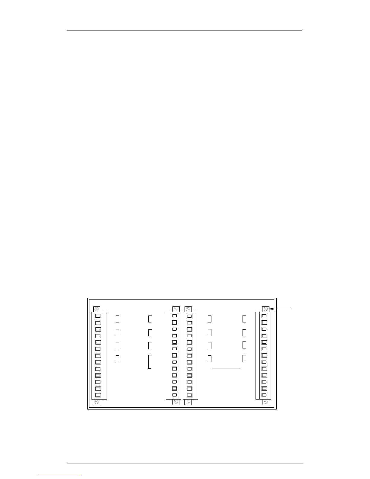
SECTION 9 - TYPICAL SMARTALARM REAR VIEW
+VE
-VE
a
b
-VE
+VE
NO
C
NC
+VFC
PS2
PS2
RLY
PS1
WD
OVCHI
OVCLO
+VB
X2
X4
X3
a
IP3
IP2
IP1
b
b
a
a
b
a
b
+VFC
a
b
a
b
b
a
b
a
+VFC
IP8
IP7
IP6
IP5
RL1
RL2
RL3
RL4
RL7
RL8
RL6
RL5
X1
a
HNB
GPB
GPA
b
a
b
b
a
HNA
b
a
PB2
PB1
PB3
PB4
PB5
a
+VFC
IP3
IP1
IP2
b
b
a
a
b
RL7
RL3
RL4
RL8
RL2
RL6
a
b
X5
RL1
RL5
a
+VFC
IP7
IP8
IP5
IP6
b
b
a
a
b
a
b
X6
IP4 IP4
Typical Rear View 16 Way SmartAlarm with repeat relays

SmartAlarm Instruction Manual Rev 2
Page 40 of 115
SECTION 10 - INSTALLATION
Unpacking
Once the item has been unpacked please visually examine the unit for any
signs of transit damage before installing the unit into the control system. If any
damage has occurred please report the damage to the freight forwarder and
copy RTK. The alarm annunciator is supplied with panel mounting clamps
locked in place, however please check all packages to ensure that no
additional pieces are left in the box as any auxiliary items like horns,
pushbuttons or spares kits will be packed separately.
Please double check that all items listed on the packing list have been
unpacked before disposing of any packing material.
Mounting
SmartAlarm annunciators are designed for panel mounting and therefore a
suitable cut-out must be provided to securely locate them using the RTK
panel mounting clamps provided on either side of the annunciator. Each
clamp can be tightened using a phillips screwdriver.
Dimensions for panel mounting versions
8 Way
Overall:- 96mm H x 96mm W x 125mm D
Cut-Out :- 91.5mm H x 91.5mm W
16 Way
Overall:- 96mm H x 144mm W x 125mm D
Cut-Out:- 91.5mm H x 139.5mm W
24 Way
Overall:- 96mm H x 192mm W x 125mm D
Cut-Out:- 91.5mm H x 187.5mm W
Please note:-
The cut out tolerance should be with ±1mm.

SmartAlarm Instruction Manual Rev 2
Page 41 of 115
19” Rack Mounting
SmartAlarms are suitable for mounting within 19” racks using suitable filler
plates which can be supplied by RTK as optional items.
Wall Mounting
RTK offer a full integration service where panel mounted annunciators are
supplied within an industry standard Wall mounting Enclosure, with all
customer connections typically wired to Weidmuller terminals for ease of
connection to the field device.
Floor Standing
RTK offer a full integration service where panel mounted annunciators are
supplied within an industry standard Floor Standing Enclosures, with all
customer connections typically wired to Weidmuller terminals for ease of
connection to the field device.

SmartAlarm Instruction Manual Rev 2
Page 42 of 115
SECTION 11 - SOFTWARE INSTALLATION
.
Configuration Software is provided free of charge on a conventional CD or the
software can be downloaded from our Website:-
www.rtkinstruments.com/downloads in the section labelled SmartAlarm
To install the software Click on the RTKSmartAlarmInstallerV***
(*** = Version Number)
Please select “Run” to start the install process.
Select “Run” which will list the components to be installed
Select “Next” which will show the default destination folder

SmartAlarm Instruction Manual Rev 2
Page 43 of 115
Select “Install” to install the application and once complete select
“Close”
The desk top will show a quick launch icon showing “RTK” within a red
shield – please select this Icon to open the application.
Select the “File” menu which will prompt the user with the following
options.

SmartAlarm Instruction Manual Rev 2
Page 44 of 115
SECTION 12 – AUTO DETECT HARDWARE.
To Auto Detect the settings within a SmartAlarm.
Open the RTK SmartAlarm configuration software using the “RTK”
quick launch icon located on the desktop.
Apply primary power to the SmartAlarm.
Remove the rubber bung on the front of the SmartAlarm to access the
USB programming port.
Connect the RTK supplied USB cable between the PC/Laptop and the
SmartAlarm.
When you initially plug-in the USB cable to the SmartAlarm you will
notice a green LED near the USB port flash to indicate communication.
From the “Comport” tool bar select the USB Com. port you will be using
to communicate with the SmartAlarm. Note the Comport No varies
depending on the devices connected to each PC and the USB port
being used therefore more than one com port may be identified in the
list.
Use the “”File” menu to select “Auto Detect” and note the green
progress bar increases whilst installation is in progress and once
complete an Auto Detect Complete message appears on the desk top
- please select “OK”.
Once Auto Detect is complete all of the settings shown will be an exact
copy of those held in the associated SmartAlarm.
You are now ready to use the software as required.
Before any configuration changes take place RTK recommend a Master copy
is saved to the PC/Laptop using the “File” menu – “Export CSV File” this
ensures a master copy is available if you wish to revert back to the initial
settings.

SmartAlarm Instruction Manual Rev 2
Page 45 of 115
SECTION 13 – IMPORT CSV FILE
Open Configuration
Configurations are saved in CSV format and can be re-installed as required.
From the “File” menu select “Import CSV File” which will allow standard
windows navigation to locate the saved configuration.
Once located select “Open” to install the previously saved configuration
settings.
Please note this will overwrite all existing settings.

SmartAlarm Instruction Manual Rev 2
Page 46 of 115
SECTION 14 – EXPORT CSV FILE
Save Configuration
Configurations are saved in CSV format and can be saved as required.
From the “File” menu select “Export CSV File” which will allow standard
windows navigation to save the configuration.
Once saved the configuration can be viewed in Microsoft Excel format and
edited as required.
After changes have been made the CSV file can be imported as described in
the previous section.
RTK recommend a copy of each SmartAlarm configuration is saved for future
reference as required.

SmartAlarm Instruction Manual Rev 2
Page 47 of 115
SECTION 15 – CREATE A NEW SYSTEM
Select “Create New SmartAlarm” is only used during manufacturing to select
the order specific features required per SmartAlarm
This function is not used by customers

SmartAlarm Instruction Manual Rev 2
Page 48 of 115
SECTION 16 – SYSTEM SETTINGS
Auto Detect
The user is able to Auto Detect the configurations of an existing SmartAlarm
once they have loaded the RTK configuration software onto a suitable PC and
connected the USB Cable to the communication port located behind the
rubber bung on the front of the SmartAlarm.
The auto detect facility is accessed via the “File” menu as shown above.
Once selected all of the settings stored within the SmartAlarm are read into
the software allowing the user to view, save or modify the configuration as
required.

SmartAlarm Instruction Manual Rev 2
Page 49 of 115
View
The following settings are available under the “View” menu.
Advanced
As standard the configuration software restricts some of the features to
simplify selection of features. In more complex applications additional menus
are available for example. Increased number of groups or custom sequences
and these are accessed via the “View Advanced” menu.
Front View of Annunciator
Selecting the “View” menu – “Front” menu provides a graphic of the alarm
fascia to aid programming.
Rear
Selecting the “View” menu – “Rear” menu provides a graphic of the rear of the
SmartAlarm showing customer terminals and designations for reference
purposes.

SmartAlarm Instruction Manual Rev 2
Page 50 of 115
Tools
The following settings are available under the “Tools” menu
Send Settings
Once the SmartAlarm has been connected to a suitable PC/Laptop via the
RTK supplied USB Cable the user is able to download any configuration
changes to the unit as required. RTK recommend that before downloading the
customer uploads the original settings and saves them on the PC/Laptop for
future reference or as a backup.
Receive Settings
Once the SmartAlarm has been connected to a suitable PC/Laptop via the
RTK supplied USB Cable the user is able to upload the configuration settings
from the unit as required. Before any changes are made RTK recommend that
a copy of the original settings are saved for future reference or as a backup.
Restore Default Settings
If required the user is able to return the unit to the factory default settings,
however please note this will revert ALL settings within the Annunciator so
should only performed with caution.

SmartAlarm Instruction Manual Rev 2
Page 51 of 115
Diagnostics
Once the SmartAlarm has been connected to a suitable PC/Laptop via the
RTK supplied USB Cable the user is able to select Diagnostics to check the
dynamic status of the SmartAlarm.
Set Structure
Please consult factory before modifying the structure of a supplied
Annunciator.
Scan Unit
This allows the user to identify the address, card type, software version and
software revision number for the cards within the SmartAlarm. This will aid
fault finding or spare parts identification.
Test Tools
Production use only.

SmartAlarm Instruction Manual Rev 2
Page 52 of 115
General Tab
The fields listed under the “General” tab allow the user to uniquely identify
each Alarm Annunciator System to aid with the storage and retrieval of
configuration data.
The user can update any of the fields within the software but the changes will
only be saved after the “Confirm Settings” control button is pressed using a
left mouse click. Any changes will need to be sent to the annunciator via the
Tools menu “Send Settings”.
Plant Name
Allows the user to allocate a unique name to define the location of the device.
Description
This field is used to identify the specific plant area or annunciator function
within the plant.

SmartAlarm Instruction Manual Rev 2
Page 53 of 115
Tag No.
This field allows a Customer assigned number to be used to identify a unique
alarm annunciator.
Serial No.
A serial number is automatically provided once the software is communicating
with the alarm annunciator.
Address Offset
This allows the user to offset the Node address to match the application.
Sleep Without Indication
Selecting this feature inhibits the heart-beat pulse which cyclically pulses the
alarm LED’s whilst the unit is in Sleep Mode (Full details of Sleep Mode are
provided within this manual).

SmartAlarm Instruction Manual Rev 2
Page 54 of 115
CS Relays (Common Service Relays)
Each channel within the annunciator can be assigned to a single or multiple
groups. The group can be software linked to any of the common relays to
provide contact outputs for use with 3rd Party devices.
The fields listed under the “CS Relays” tab allow the user to configure the
common system relays to follow groups as required.
Horn A - HNA
The default setting for this relay is Horn A / HNA, the relay is normally deenegised and provides a N/O contact for use with external audibles / 3rd party
devices. The relay will activate on alarm and will return to normal after Mute or
Acknowledge have been pressed. The relay must be assigned to a group and
the group type needs to be set as “Audible” for the relay to operate correctly.
The coil state can be set to Normally Energised or Normally De-
Energised, by selecting the required feature using the Drop-down
menu shown next to the coil status field.

SmartAlarm Instruction Manual Rev 2
Page 55 of 115
Horn B - HNB
The default setting for this relay is Horn B / HNB, the relay is normally deenergised and provides a N/O contact for use with external audibles / 3rd party
devices. The relay will activate on alarm and will return to normal after Mute or
Acknowledge have been pressed. The relay must be assigned to a group and
the group type needs to be set as “Audible” for the relay to operate correctly.
The coil state can be set to Normally Energised or Normally De-
Energised, by selecting the required feature using the Drop-down
menu shown next to the coil status field.
Group A - GPA
The default setting for this relay is Group A / GPA, the relay is normally deenergised and provides a configurable contact for use with 3rd party devices.
The relay will activate on alarm and will return to normal after the process has
returned to normal and the alarm has been cleared. The relay must be
assigned to a group and the group type needs to be set as “Alarm” for the
relay to operate correctly.
A latching Relay is used for the Group Relay function allowing the
contact state can be set to Normally Open or Normally Closed by
selecting the required feature using the Drop-down menu shown next
to the coil status field.
Group B - GPB
The default setting for this relay is Group B / GPB, the relay is normally deenergised and provides a configurable contact for use with 3rd party devices.
The relay will activate on alarm and will return to normal after the process has
returned to normal and the alarm has been cleared. The relay must be
assigned to a group and the group type needs to be set as “Alarm” for the
relay to operate correctly.
A latching relay is used for the Group Relay function allowing the
contact state can be set to Normally Open or Normally Closed by
selecting the required feature using the Drop-down menu shown next
to the coil status field.
Optional Settings
The following options apply to any of the common relays.
Assigning Relays to Groups
Any relay can be set to follow any group within the annunciator using the drop
down menu.

SmartAlarm Instruction Manual Rev 2
Page 56 of 115
Reflash Function
When using the GPA or GPB common alarm relays a reflash function can be
used to indicate that multiple alarms are occurring within the group. When an
alarm within the group activates the relay will change state and each time a
new alarm occurs within the same group the relay will revert to normal and
reactivate, (Reflash). The drop-down menu which allows selection of the
group includes selection of the group and reflash as an option.
Disable in System Test
A relay can be prevented from operating during System Test by selecting the
“Disable in System Test” check box shown on the previous page. For example
you may not need the audible to sound during system test, this feature allows
the user to disable the relay during the test cycle.
Disable in Sleep Mode
Sleep mode is an optional setting which allows the user to disable the visual,
audible and common relays during unmanned periods.
A relay can be prevented from operating whilst the annunciator is in sleep
mode by selecting the “Disable in Sleep Mode” check box shown above. For
example you may wish to disable the horn relays but allow the common alarm
relays to continue to operate as normal during unmanned periods.
Reflash Pulse Length
As indicated above the group relays can have a reflash feature enabled which
interrupts the output each time a new alarm occurs within the group. The
reflash pulse length can be set in tenths of a second to suit individual
applications.
Alternative Functions for any Relay
The drop-down menu provided next to the “Assignment Field” of each relay
allows the user to set any of the Relays to:-
Any group (Group-1 to Group-30).
Any group with Reflash enabled (Group-1 to Group-30).
Pushbutton Follower where the relay will faithfully follow the operation
of any one of the following Pushbutton functions:- Lamp Test, Mute,
Ack, Reset, 1st Reset or System Test.
All faults Relay where the relay activates if any fault is detected within
the Annunciator.
Field Contact fault where the relay activates when the signal supply is
lost which can be used to flag 3rd Party devices.

SmartAlarm Instruction Manual Rev 2
Page 57 of 115
Local Pushbuttons
Each SmartAlarm is equipped with four integral tactile pushbuttons used to
control the operational sequence of the annunciator. The local pushbuttons
tab allows the user to change the function of a pushbutton if required.
A drop-down menu provided per pushbutton allows the user to select
alternative functions. For example System Test is used as standard but the
user may prefer Lamp Test as an option.
Once the alternative function has been selected the user will need to press
“Confirm” and the changes will need to be downloaded to the annunciator via
the tools menu.
Any internal pushbutton can be assigned to a pushbutton group and any
channel can be set to match the associated group.
For example:- Channel-1 to 4 can be set to Pushbutton Group-1 and the
internal pushbuttons can be set to control Pushbutton Group-1. Only alarms
within the group would be controlled by the internal pushbuttons.
The remaining alarms can be assigned to Pushbutton Group-2 and these can
be controlled by external pushbuttons if required.
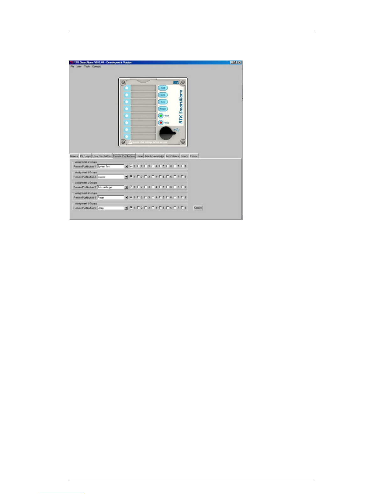
SmartAlarm Instruction Manual Rev 2
Page 58 of 115
Remote Pushbuttons
Each SmartAlarm is equipped with five optically coupled digital inputs which
can be used with normally open momentary pushbuttons to control the
operational sequence of the annunciator. The remote pushbuttons tab allows
the user to change the function of a pushbutton if required.
A drop-down menu provided per pushbutton allows the user to select
alternative functions. For example System Test is used as standard but the
user may prefer Lamp Test as an option.
Once the alternative function has been selected the user will need to select
“Confirm” and the changes will need to be downloaded to the annunciator via
the tools menu – “send settings”.
Any external pushbutton can be assigned to a pushbutton group and any
channel can be set to match the associated group.
For example:- Channel-1 to 4 can be set to Pushbutton Group-1 and the
internal pushbuttons can be set to control Pushbutton Group-1. Only alarms
within the group would be controlled by the internal pushbuttons.
The remaining alarms can be assigned to Pushbutton Group-2 and these can
be controlled by external pushbuttons if required.

SmartAlarm Instruction Manual Rev 2
Page 59 of 115
Inhibit Function
As an alternative any of the five pushbutton inputs can be set for use with an
external inhibit switch. The inhibit switch should be connected between +VB
and the associated pushbutton input. When the switch is in the closed position
all alarms within the inhibit group will be prevented from operating until the
inhibit switch is returned to normal
It is possible to assign any channel with the Annunciator to be included in
inhibit group-1 to inhibit group-8 as required
To link a channel to an inhibit group first select the associated LED within the
software faceplate to access the “channel”-tab.
Under the “Manual Inhibit” field assign the channel to an inhibit group as
required and select “Confirm” followed by “Tools” – “Send Settings” to
download the settings to the Annunciator.
Assigning Channel to Inhibit Groups
In the above example channel 3 has been set to Inhibit Group 1
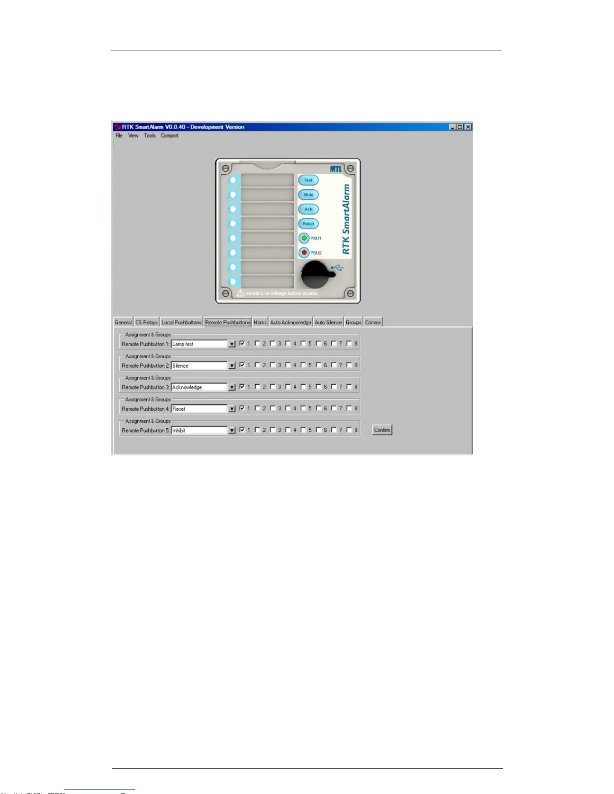
SmartAlarm Instruction Manual Rev 2
Page 60 of 115
Assigning a Remote Pushbutton Input to Inhibit
In the above example Remote Pushbutton 5 has been set as the Input for
Group 1 Inhibit Switch

SmartAlarm Instruction Manual Rev 2
Page 61 of 115
Sleep Mode
As an alternative any of the five pushbutton inputs can be set for use with an
external inhibit switch used to place the Annunciator into Sleep Mode during
unmanned periods. The sleep mode switch should be connected between
+VB and the associated pushbutton input.
a
b
a
b
a
b
a
b
PB1
PB2
PB3
PB4
PB5
HNA
HNB
GPA
GPB
X1
+VB
ATTENDED / UNATTENDED
SWITCH
PB5 for remote pushbutton-5 Used as a Sleep Mode Input.
Assigning a Remote Pushbutton Input to Sleep Mode

SmartAlarm Instruction Manual Rev 2
Page 62 of 115
Whilst in sleep mode the audible alarms are disabled and the individual
channel LED’s are disabled to save power and prevent noise pollution during
unmanned periods.
When the switch is maintained in the closed position the Annunciator will
remain in sleep mode until the switch is returned to normal.
Please note:-
The individual channel repeat relays will continue to operate as usual
during sleep mode to allow notification of alarms to 3rd Party devices
The two group relays GPA, GPB & the Watchdog relay can be
prevented from operating in sleep mode under the Common Services
Relays – Tab if required.
In the above example Remote Pushbutton 5 has been set as an input for the
external “Attended / Unattended” sleep mode switch.

SmartAlarm Instruction Manual Rev 2
Page 63 of 115
Common Relay Operating In Sleep Mode
Each of the common relays can be prevented from operating in “Sleep” mode
if required.
For example during unmanned periods the two horn relays can be prevented
from operating to prevent noise pollution whilst the 2 Group and 1 Watchdog
relay can continue to operate as normal.
Inhibiting Common Relays During Sleep Mode
In the above example HNA and HNB horn relays will not operated during
sleep mode.

SmartAlarm Instruction Manual Rev 2
Page 64 of 115
Sleep Mode Heartbeat
To indicate that the annunciator is in sleep mode the associated alarm LED’s
pulse periodically (heart beat pulse).
In some applications this pulse may not be required and it can be disabled by
selecting “Sleep Without Indication” under the “General” tab as shown in the
below screenshot. Once the setting has been made select “Confirm” – “Tools”
menu – “Send Settings” to download the changes to the SmartAlarm.
Disabling Sleep Mode Heartbeat

SmartAlarm Instruction Manual Rev 2
Page 65 of 115
Horn
As standard the user can assign any channel to any group within the
annunciator.
A maximum of 32 groups are available however to simplify configuration in the
normal view only 8 groups are shown.
The remaining groups can be accessed if the user selects “View” followed by
“Advanced”.
Once the alarms have been assigned to groups and the group type has been
set to “Audible” the group or groups can be linked to the internal audible as
required.
For example
If channels 1 to 8 have been set to Group-1
The Group type has been set to “Audible”
The internal horn-1 can be linked to the group by selecting Group-1
under the horns tab
Screen shot shown above for reference.

SmartAlarm Instruction Manual Rev 2
Page 66 of 115
Auto Acknowledge
In applications where the annunciator is left unattended for long periods noise
pollution can be prevented using the automatic acknowledge feature.
This feature is used to assign the automatic acknowledge function to the
associated group.
In the normal view 8 groups are shown as standard and the remaining groups
can be accessed if the user selects “View” followed by “Advanced”
The “delay” field allows the user to enter a time delay in seconds and once set
the annunciator will automatically acknowledge the alarms after the pre-set
period has elapsed.
The automatic acknowledge feature will silence the audible and the visual
alarm will also be acknowledged in accordance with the selected ISA
sequence.
Please note as the timer is triggered from the horn circuit the user must select
automatic acknowledge OR automatic silence as either function will stop the
timer.

SmartAlarm Instruction Manual Rev 2
Page 67 of 115
Auto Silence
In applications where the annunciator is left unattended for long periods noise
pollution can be prevented using the automatic silence feature.
This feature is selected under the auto silence tab where the user can assign
the automatic silence function to the associated group.
In the normal view 8 groups are shown as standard and the remaining groups
can be accessed if the user selects “View” followed by “Advanced”
The “delay” field allows the user to enter a time delay in seconds and once set
the annunciator will automatically silence the audible after the pre-set period
has elapsed.
Please note
1. This feature only silences the audible alarm the visual alarm will
continue to operate in accordance with the selected ISA sequence.
2. The timer is triggered from the horn circuit therefore the user must
select automatic acknowledge OR automatic silence as either function
will stop the timer.

SmartAlarm Instruction Manual Rev 2
Page 68 of 115
Groups
Any channel within the Annunciator can be set to be part of Group-1 to Group32 as required.
Group Types
First-Up Group
In applications where the annunciator is monitoring alarms which are
interlinked for example: Compressor and Turbine monitoring it is important to
identify the first alarm to occur within the group as it simplifies and quickly
identifies the root cause of failure.
Once the alarms have been assigned to a group the “Groups” function needs
to be identified using the drop-down menu provided against each group.
For example if channel 1 to 8 have been assigned to Group-8 and they are all
part of the same first-up group the drop-down menu for Group-8 should be set
to “First-Up Group”
Input Group
Input Groups are typically used with Common Relays GPA and / or GPB and
3rd party devices to identify that an alarm / alarms with a group are in the
abnormal condition.
With “Input Groups” the common relay would activate when an alarm in the
group occurs and the common relay would automatically return to normal
when the Input returns to normal.

SmartAlarm Instruction Manual Rev 2
Page 69 of 115
Please note if multiple channels are used with the Group - ALL of the alarms
must be in the non-alarm state before the common relay returns to normal.
Any channel within the Annunciator can be assigned to any group and once
assigned the “Groups” function needs to be set to “Input Group” using the
drop-down menu provided against each group as required.
Once set the Common Relay / Relays need to match to follow the Group as
required.
Audible Group
Any channel within the Annunciator can be assigned to any group and once
assigned the “Groups” function needs to be set using the drop-down menu
provided against each group
For example if channel 1 to 8 have been assigned to “Group-1” and they are
all part of the same audible group the drop-down menu for Group-1 should be
set to “Audible Group”
Once selected the Internal Audible or Common Relays should be set to follow
the associated horn group as required.
Ring back Audible Group
When using ISA R – Ring Back Sequence the associated LED slow flashes to
indicate to the operator that an alarm has returned to normal.
In addition to the visual prompt the annunciator can sound an audible to
prompt the operator that Reset can be pressed to clear the alarm.
Alarms set to alarm sequence ISA R (Ring Back) and a Group for example
Group-7 can be set to a RB (Ring Back) Audible Group using the drop down
menu provided against Group 7.
Group 7 can be typically assigned to HNB Horn Relay B and an external horn
differing in tone from the integral audible can be used to identify that an alarm
has returned to normal.

SmartAlarm Instruction Manual Rev 2
Page 70 of 115
Grouping Example
The following steps identify how to set the Group, Group Type and assign the
Group to Internal Horn and Common Relays.
In the above example ALL channels have be set to “Group 1”
Assigning the Group Type
In the above example the “Group Type” has been set to Audible.

SmartAlarm Instruction Manual Rev 2
Page 71 of 115
Assigning a Group to the Internal Audible
In the above example the internal horn has been set to follow “Group 1”
Assigning a Group to a Common Relay
In the above example Common Relay Horn A / HNA has been set to follow
“Group 1”

SmartAlarm Instruction Manual Rev 2
Page 72 of 115
Comm’s
As an option the Annunciator can be provided with Modbus RTU Protocol for
use with 3rd Party devices.
When this option is included the Comm’s – Tab provides access to the fields
used to set the following:-
Protocol – Modbus RTU
Baud Rate – 38400, 19200 or 9600
Parity – Even or Odd
Normal Delay – Set in mS
Communications Address Offset – Set as required to match the 3rd
Party device

SmartAlarm Instruction Manual Rev 2
Page 73 of 115
SECTION 17 – INDIVIDUAL CHANNEL SETTINGS
Configuring Individual Channels
To configure individual channels the user must first select an LED on the
associated annunciator faceplate using a left mouse click as typically shown
below for channel-1.
Configuring Selective channels
Selective channels can be highlighted if the “Ctrl” key on the keyboard is held
down while you select the required LED icons (Channels). Once the channels
have been selected the user is able to navigate between features and select
them as required. The background colour for a selected feature is white
however if the background colour changes to blue it indicates that the
selected channels currently have varying settings stored and the user will be
prompted if they wish to proceed in setting them to the same function.
Configuring Multiple channels
Multiple channels can be highlighted if the user selects the first LED and holds
down the shift –key on the keyboard to select the last LED in the group. For
example if you select channel-1 and hold down the shift-key and select
channel-8 all channels within the range will be selected.
To implement changes the user must select the “Confirm” icon and download
the configuration to the SmartAlarm using the “Tools” menu – “Send Settings”
as required

SmartAlarm Instruction Manual Rev 2
Page 74 of 115
Channel
The following options are available “Channel” tab
Alarm Legend
Each channel needs to have a unique legend to help the operator identify the
alarm. The user can type an alarm description into the “alarm legend” field
and dropdown menus allow selection of window colour, font, style and size to
suit each application.
Manual Inhibit
Each channel can be manually inhibited within the software or a number of
channels can be assigned to an inhibit group to allow a remote switch input to
be used as a group inhibit enable. To manually inhibit a channel the user
selects the associated LED icon and then uses a left mouse click to select the
inhibit input tick-box under the channel tab.
Group Inhibit
If inhibit groups are required channels should be selected to the required
group and the group should be assigned to a remote pushbutton/switch input
as described later in the manual.
To implement changes the user must select the “Confirm” icon and download
the configuration to the SmartAlarm using the “Tools” menu – “Send Settings”
as required

SmartAlarm Instruction Manual Rev 2
Page 75 of 115
Auto Shelving
On systems supplied with the sequence of event recording option a faulty
alarm loop or loose cable can quickly flood the associated event buffers. Auto
Shelve allows the user to configure:
Function Description
Alarm Count The maximum number of alarms the user believes will
occur with a set period before the alarm count is
considered abnormal.
Count Period The required time period in seconds
If the number of input events exceeds the abnormal count within the time
period the input will be automatically shelved and a dated and timed message
will be generated to inform the user that auto shelving has occurred on the
specific channel. Events that occurred prior to the auto shelve are stored in
buffer to aid fault finding and the alarm will return to normal once the input is
within operating parameters.
To implement changes the user must select the “Confirm” icon and download
the configuration to the SmartAlarm using the “Tools” menu – “Send Settings”
as required

SmartAlarm Instruction Manual Rev 2
Page 76 of 115
Input
The following options are available under the “Input” tab
Contact Type
A dropdown menu allows the user to assign the non-alarm contact state for
each channel. The default setting is Normally Open (Closed to alarm) with an
optional setting to Normally Closed (Open to alarm). If serial inputs are
required please select the tick-box to the left of “Remote”
Delay Timers
Each channel is equipped with timers allowing the user to delay the activation
and/or the return to normal time period.
Abnormal Delay (mS)
This option prevents the alarm occurring before a pre-set time period has
elapsed. If an alarm occurs the timer will automatically start and the alarm will
occur as soon as the delay period has passed.
Normal Delay (mS)
This option prevents the alarm returning to normal until the pre-set delay
period has elapsed.
The default setting for the activation and deactivation is 10mS but can be
selected between 1 and 65,000mS as required.

SmartAlarm Instruction Manual Rev 2
Page 77 of 115
Remote
This field is used to configure each input as hardwire (Normally Open /
Normally Closed) or Serial Input (Remote).
If the “Remote” check-box is enabled the input will activate via Serial
Communications.
If the “Remote” check-box is unchecked the input will activate via a
conventional hardwired contact input (N/O or N/C).
To implement changes the user must select the “Confirm” icon and download
the configuration to the SmartAlarm using the “Tools” menu – “Send Settings”
as required

SmartAlarm Instruction Manual Rev 2
Page 78 of 115
Relay
As an option which must be specified at time of order, each channel can be
provided with a repeat relay on the 8, 16 and 24 way versions of the
SmartAlarm.
If the relay tab is greyed out repeat relays have not been fitted.
If the relay tab is active the following settings are available.
Coil Status
The non-alarm coil state of each relay can be set to Normally Energised or
Normally De-Energised using the dropdown menu as required.
Relay Function
The function of each relay can be set to one of the following modes using the
dropdown menu:-
Follow Input
In this mode the relay will operate when the signal contact activates
and returns to normal.
Follow Alarm
In the mode the relay will activate on alarm and will only change state
when the input returns to normal and the alarm has been cleared.
Follow Display
In this mode the relay will faithfully follow the display i.e. ON / OFF or
Flashing to match the alarm sequence.

SmartAlarm Instruction Manual Rev 2
Page 79 of 115
Abnormal Delay
Each repeat relay can be set to activate after a pre-set time has elapsed.
The default is 10mS and the user can increment this in 1mS steps upto a
maximum of 65,000mS.
Normal Delay
Each repeat relay can be prevented from returning to normal unless the
change in state has occurred for longer than the pre-set time period.
The default is 10mS and the user can increment this in 1mS steps upto a
maximum of 65,000mS.
To implement changes the user must select the “Confirm” icon and download
the configuration to the SmartAlarm using the “Tools” menu – “Send Settings”
as required

SmartAlarm Instruction Manual Rev 2
Page 80 of 115
Sequence
The following settings are available under the “Sequence” tab
Within the annunciator market a common standard has been adopted by all
key manufacturers and end users with regards to operational sequences.
These standards are used worldwide to define the visual indication, audible
alarm and the action the operator must take to control the annunciator.
The Instrument Society of America provide full details of each alarm sequence
within ISA 18.1-1979 (R1992) and RTK are fully compliant with the stated
sequences. The most common sequences are detailed in a separate section
of the manual.
ISA Sequences
To define a sequence the user can simply select any of the listed ISA
sequences on a per channel basis using the dropdown menu as shown
below.
The additional features shown i.e. Basic Sequence, First-Up Sequence and
Sequence Options are only visible when the user selects view-“Advanced”
and these options are used for custom sequences.
To implement changes the user must select the “Confirm” icon and download
the configuration to the SmartAlarm using the “Tools” menu – “Send Settings”
as required
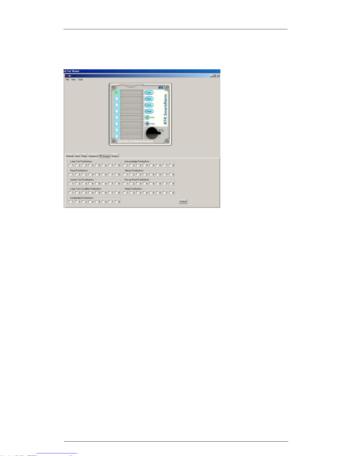
SmartAlarm Instruction Manual Rev 2
Page 81 of 115
PB Groups
The following settings are available under the “PB Groups” tab.
Global Pushbutton Group
Pushbutton functions are available within the SmartAlarm to test or control the
alarms in accordance ISA-S18.1 Alarm Sequences.
In standard applications all channels are assigned to pushbutton group-1
however, the user can enable or disable any of the functions on a per channel
basis as required.
Multiple Pushbutton Groups
In more complex applications each channel can be assigned to any one of 8
pushbutton groups. To access the additional groups the user must select
“View” followed by “Advanced” view.
As a default Pushbutton Group-1 is assigned to the internal pushbuttons and
any additional pushbutton groups would require the use of external
pushbuttons.
To implement changes the user must select the “Confirm” icon and download
the configuration to the SmartAlarm using the “Tools” menu – “Send Settings”
as required

SmartAlarm Instruction Manual Rev 2
Page 82 of 115
Groups
The following settings are available under the “Groups” tab.
Each channel within the SmartAlarm can be linked to a single or multiple
alarm groups. Groups-1 to 8 are shown as standard and additional groups are
available via the “View” – “Advance View” menu.
Groups are typically used to provide summary alarm information for use with
3rd Party devices (DCS/PLC/SCADA/Supervisor Consoles).
Channels can be assigned to a single or multiple groups using a left mouse
click on the associated tick-box.
To implement changes the user must select the “Confirm” icon and download
the configuration to the SmartAlarm using the “Tools” menu – “Send Settings”
as required

SmartAlarm Instruction Manual Rev 2
Page 83 of 115
SECTION 18 – ALARM SEQUENCES
Within the annunciator market a common standard has been adopted by all
key manufacturers and end users with regards to operational sequences.
These standards are used worldwide to define the visual indication, audible
alarm and the action the operator must take to control the annunciator.
The Instrument Society of America provide full details of each alarm sequence
within ISA 18.1-1979 (R1992) and RTK are fully compliant with the stated
sequences. The most common sequences are detailed within this section of
the manual.
To define a sequence the user can simply select any of the listed ISA
sequences.
Pushbuttons
Four integral pushbuttons and five remote pushbutton inputs are provided on
the annunciator unit to allow the user to be able to control any of the available
sequences which can be set on a per channel basis.
Functional Test – is used to simulate an input on all channels and therefore
all windows and horn circuits will operate in accordance with the selected ISA
sequence and additional pushbuttons will need to be pressed to step through
the alarm sequence to return the unit to its normal state.
Mute – is used to silence the audible alarm whilst allowing the associated
alarm window to continue to operate in accordance with the selected ISA
sequence.
Acknowledge – is used to silence the alarm and change the state of the
associated alarm window in accordance with the selected ISA sequence.
Reset – is used to return the alarm to the normal off state once the Input has
returned to the normal condition.
As an option functional test can be replaced by Lamp Test and Reset can be
replaced by First Reset if required.
Audible Alarms
Each channel within the annunciator can be set to operate either of the two
integral audible alarms or they can be assigned to common relays configured
as horn relays as required.

SmartAlarm Instruction Manual Rev 2
Page 84 of 115
Additional Features
Automatic Reset
Once a channel has been acknowledged and its input has returned to normal
the alarm can be set to automatically reset without the operator having to
press the reset pushbutton.
Non Latch Sequence – (No Lock In)
Alarms can be set to non lock-in, which allows the alarm to automatically
return to the non alarm state as soon as the signal input returns to normal.
Ringback Sequence
Ringback sequence is used to inform the operator both visually and audibly
that an alarm condition has cleared and the channel can be reset to its normal
off state. When a contact returns to normal the associated window will flash at
approx ½ the speed of a normal alarm and the audible will sound. This
identifies the specific alarm and informs the operator that the alarm can be
reset to its normal off state.
First Up Sequences
When monitoring devices with interlinked functions such as a turbine or
compressor it is often important to know the specific alarm that occurred first,
as it will invariably result in cascade of secondary alarms. This allows the
operator to focus on the root cause of failure and therefore limits the
downtime and associated costs. This is achieved by having the first-up alarm
flashing in a different manner compared to the subsequent alarms. Four
different first-up sequences are available F0, F1, F2 and F3 as detailed below
and in the following sequence tables.
F0 The standard mode adopted by RTK Instruments, which indicates the first-
up alarm by flashing at twice the rate of subsequent alarms.
F1 In this mode subsequent alarms appear in the acknowledged state, hence
they do not flash. The audible device does not operate when subsequent
alarms occur, unless still operating from the first alarm. The acknowledge
pushbutton will reset the first-up indication.
F2 In this mode all subsequent alarms do not flash, they will however operate
the audible device. The acknowledge pushbutton will reset the first-up
indication.
F3 In this mode initial alarms appear with an intermittent flash rate and
subsequent alarms flash at a steady rate. On acknowledge subsequent
alarms revert to the steady on state and only the first alarm continues to
flash at a slower rate.
Please note auto reset and non lock- in functions are not recommended when
using first up sequences as the true sequence of events cannot be
guaranteed.
The most common sequences are detailed below:-

SmartAlarm Instruction Manual Rev 2
Page 85 of 115
ISA A – Automatic Reset – Lock In
PROCESS
SEQUENCE
VISUAL
AUDIBLE
ABNORMAL
OR NORMAL
ALARM
FLASHING
AUDIBLE
SEQUENCE
PROCESS
OFFVISUAL
AUDIBLE
SILENT
NORMAL
NORMAL
ACKNOWLEDGE
WHILE ABNORMAL
RETURN
TO NORMAL
TO
ABNORMAL
ACKNOWLWDGE
WHILE NORMAL
AUDIBLE
VISUAL
SEQUENCE
PROCESS
ABNORMAL
OR NORMAL
SILENT
ON
ACKNOW
Sequence Features
1. Acknowledge and test pushbuttons.
2. Alarm audible device
3. Lock In of momentary alarms until acknowledged
4. The Audible device is silenced and the flashing stops when
acknowledged.
5. Automatic reset of acknowledged alarms when the process has
returned to normal
6. Operational test

SmartAlarm Instruction Manual Rev 2
Page 86 of 115
ISA A-1-2 – Automatic Reset – Silence Pushbutton Interlock
PROCESS
SEQUENCE
VISUAL
AUDIBLE
ABNORMAL
OR NORMAL
ALARM
FLASHING
AUDIBLE
SEQUENCE
PROCESS
OFFVISUAL
AUDIBLE
SILENT
NORMAL
NORMAL
SILENCE
RETURN
TO NORMAL
TO
ABNORMAL
ACKNOWLEDGE
AUDIBLE
VISUAL
SEQUENCE
PROCESS
ABNORMAL
OR NORMAL
SILENT
FLASHING
SILENCE
ABNORMAL
OR NORMAL
PROCESS
VISUAL
AUDIBLE
SEQUENCE
ON
SILENT
ACKNOW
Sequence Features
1. Acknowledge, silence and test pushbuttons.
2. Alarm audible device
3. Lock In of momentary alarms until acknowledged
4. Silence pushbutton must be pressed before acknowledge
5. Silence stops the audible alarm only
6. The flashing stops when acknowledged.
7. Automatic reset of acknowledged alarms when the process has
returned to normal
8. Operational test

SmartAlarm Instruction Manual Rev 2
Page 87 of 115
ISA A-4 – Automatic Reset – Non Lock In
PROCESS
SEQUENCE
VISUAL
AUDIBLE
ABNORMAL
OR NORMAL
ALARM
FLASHING
AUDIBLE
SEQUENCE
PROCESS
OFFVISUAL
AUDIBLE
SILENT
NORMAL
NORMAL
ACKNOWLEDGE
WHILE ABNORMAL
RETURN
TO NORMAL
TO
ABNORMAL
RETURN
TO NORMAL
AUDIBLE
VISUAL
SEQUENCE
PROCESS
ABNORMAL
OR NORMAL
SILENT
ON
ACKNOW
Sequence Features
1. Acknowledge, and test pushbuttons.
2. Alarm audible device
3. Non Lock In of momentary alarms
4. The audible device is silenced and the flashing stops when
acknowledged.
5. Automatic reset of alarms when the process has returned to normal
before or after acknowledge (Non Lock In)
6. Operational test

SmartAlarm Instruction Manual Rev 2
Page 88 of 115
ISA A-4-5 – Automatic Reset – No Flashing
PROCESS
SEQUENCE
VISUAL
AUDIBLE
ABNORMAL
OR NORMAL
ALARM
ON
AUDIBLE
SEQUENCE
PROCESS
OFF
VISUAL
AUDIBLE
SILENT
NORMAL
NORMAL
ACKNOWLEDGE
WHILE ABNORMAL
RETURN
TO NORMAL
TO
ABNORMAL
RETURN
TO NORMAL
AUDIBLE
VISUAL
SEQUENCE
PROCESS
ABNORMAL
OR NORMAL
SILENT
ON
ACKNOW
Sequence Features
1. Acknowledge, and test pushbuttons.
2. Alarm audible device
3. The visual alarm does not flash
4. Non Lock In of momentary alarms
5. The audible device is silenced when acknowledged.
6. Automatic reset of acknowledged alarms when the process has
returned to normal
7. Operational test

SmartAlarm Instruction Manual Rev 2
Page 89 of 115
ISA A-4-5-6 – Status
PROCESS
SEQUENCE
VISUAL
AUDIBLE
ABNORMAL
OR NORMAL
ALARM
ON
SILENT
SEQUENCE
PROCESS
OFFVISUAL
AUDIBLE
SILENT
NORMAL
NORMAL
RETURN
TO NORMAL
TO
ABNORMAL
Sequence Features
1. Test pushbutton.
2. No alarm audible
3. The visual alarm does not flash
4. Non Lock In of momentary alarms
5. Automatic reset of alarms when the process has returned to normal
before or after acknowledge (Non Lock In)
6. Operational test

SmartAlarm Instruction Manual Rev 2
Page 90 of 115
Please Note:-
The drop down menu within the configuration software allows the user to
select ISA Sequence A-4-5-6 to obtain Status Only indication.
If the audible alarm sounds on a channel that has been set to Status only
please check that the channel is not part of a “Group” which has been
assigned to operate as an “Audible” under the group operations tab.
In the example below Group 8 is being used as an audible group.
Group Tab
This screen shot indicates that a channel has been set to Group 8.
Group Operations Tab
This screen shot indicates that Group “Type” for Group 8 has been set to
operate as “Audible”.
To prevent the audible sounding the user should select the associated alarm
LED on the software faceplate and uncheck the tick box associated with any
Group being used as an Audible in the example above this would be Group 8.

SmartAlarm Instruction Manual Rev 2
Page 91 of 115
ISA A-5 – Automatic Reset – No Flash
PROCESS
SEQUENCE
VISUAL
AUDIBLE
ABNORMAL
OR NORMAL
ALARM
ON
AUDIBLE
SEQUENCE
PROCESS
OFFVISUAL
AUDIBLE
SILENT
NORMAL
NORMAL
ACKNOWLEDGE
WHILE ABNORMAL
RETURN
TO NORMAL
TO
ABNORMAL
ACKNOWLWDGE
WHILE NORMAL
AUDIBLE
VISUAL
SEQUENCE
PROCESS
ABNORMAL
OR NORMAL
SILENT
ON
ACKNOW
Sequence Features
1. Acknowledge and test pushbuttons.
2. Alarm audible device
3. The visual alarm does not flash
4. Lock In of momentary alarms until acknowledged
5. The Audible device is silenced when acknowledged.
6. Automatic reset of acknowledged alarms when the process has
returned to normal
7. Operational test

SmartAlarm Instruction Manual Rev 2
Page 92 of 115
ISA M – Manual Reset – Lock In
PROCESS
SEQUENCE
VISUAL
AUDIBLE
ABNORMAL
OR NORMAL
ALARM
FLASHING
AUDIBLE
SEQUENCE
PROCESS
OFFVISUAL
AUDIBLE
SILENT
NORMAL
NORMAL
ACKNOWLEDGE
WHILE ABNORMAL
RESET
WHILE NORMAL
TO
ABNORMAL
AUDIBLE
VISUAL
SEQUENCE
PROCESS
ABNORMAL
OR NORMAL
SILENT
ON
ACKNOW.
Sequence Features
1. Acknowledge, reset and test pushbuttons.
2. Alarm audible device
3. Lock In of momentary alarms until acknowledged
4. The Audible device is silenced and the flashing visual alarm stops
when acknowledged.
5. Manual reset of acknowledged alarms when the process has returned
to normal
6. Operational test

SmartAlarm Instruction Manual Rev 2
Page 93 of 115
ISA M-1-2 – Manual Reset – Silence Pushbutton Interlock
PROCESS
SEQUENCE
VISUAL
AUDIBLE
ABNORMAL
OR NORMAL
ALARM
FLASHING
AUDIBLE
SEQUENCE
PROCESS
OFFVISUAL
AUDIBLE
SILENT
NORMAL
NORMAL
SILENCE
RESET
WHILE NORMAL
TO
ABNORMAL
ACKNOWLEDGE
AUDIBLE
VISUAL
SEQUENCE
PROCESS
ABNORMAL
OR NORMAL
SILENT
FLASHING
SILENCE
ABNORMAL
OR NORMAL
PROCESS
VISUAL
AUDIBLE
SEQUENCE
ON
SILENT
ACKNOW
Sequence Features
1. Acknowledge, reset and test pushbuttons.
2. Alarm audible device
3. Lock In of momentary alarms until acknowledged
4. Silence pushbutton must be pressed before acknowledge
5. Silence stops the audible alarm only
6. The flashing stops when acknowledged.
7. Manual reset of acknowledged alarms when the process has returned
to normal
8. Operational test

SmartAlarm Instruction Manual Rev 2
Page 94 of 115
ISA R – Ringback
PROCESS
SEQUENCE
VISUAL
AUDIBLE
ABNORMAL
OR NORMAL
ALARM
FAST FLASH
AUDIBLE
SEQUENCE
PROCESS
OFFVISUAL
AUDIBLE
SILENT
NORMAL
NORMAL
AUDIBLE
VISUAL
SEQUENCE
PROCESS ABNORMAL
SILENT
ON
ACKNOW
NORMALPROCESS
VISUAL
SEQUENCE
SLOW FLASH
RINGBACK
TO ABNORMALRESET
RETURN
TO NORMAL
RETURN TO ABNORMAL
ACK WHILE NORMAL
ACKNOW
WHILE ABNORMAL
RINGBACK
AUDIBLE
PULSING
Sequence Features
1. Acknowledge, reset and test pushbuttons.
2. Alarm audible device. (optional Ringback audible device)
3. Lock In of momentary alarms until acknowledged
4. The audible device is silenced and the flashing stops when
acknowledged
5. Ringback visual ad audible indications when the process condition
returns to normal
6. Manual reset of Ringback indications
7. Operational test

SmartAlarm Instruction Manual Rev 2
Page 95 of 115
ISA F1A-1 – Automatic Reset First Up
PROCESS
SEQUENCE
VISUAL
AUDIBLE
ABNORMAL
OR NORMAL
FIRST ALARM
FLASHING
AUDIBLE
SEQUENCE
PROCESS
OFFVISUAL
AUDIBLE
SILENT
NORMAL
NORMAL
ACKNOWLEDGE
WHILE ABNORMAL
(FIRST OUT RESET)
RETURN
TO NORMAL
FIRST TO
ABNORMAL
AUDIBLE
VISUAL
SEQUENCE
PROCESS ABNORMAL
SILENT
ON
ACKNOW.
SUBSEQUENT
TO ABNORMAL
Sequence Features
1. Acknowledge and test pushbuttons.
2. Alarm audible device
3. Lock In of momentary first alarm only, no lock in of momentary
subsequent alarms
4. Flashing and audible indications for first alarm only, new subsequent
alarms go to the acknowledge state.
5. First out indication is reset and the audible is silenced when
acknowledged.
6. Automatic Reset of acknowledged alarm indications when the process
returns to normal
7. Silence pushbutton can be used to silence the audible alarm only

SmartAlarm Instruction Manual Rev 2
Page 96 of 115
ISA F2M-1 – Manual Reset First Up
PROCESS
AUDIBLE
VISUAL
SEQUENCE
ACKNOWLEDGE
VISUAL ON
FIRST ALARM
SEQUENCE ISA F2M-1
(MANUAL RESET FIRST OUT WITH NO SUBSEQUENT ALARM FLASHING & SILENCED PUSHBUTTON)
AUDIBLE
ACKNOWLEDGE
(FIRST OUT RESET)
VISUAL
SEQEUNCE
PROCESS
SILENT
FLASHING
FIRST SILENCED
SILENCE
ACKNOWLEDGE
(FIRST OUT RESET)
SILENT
ACKNOWLEDGED
ON
AUDIBLE
AUDIBLE
VISUAL
SEQUENCE
ON
PROCESS
AUDIBLE
FLASHING
ABNORMAL
SILENCE
PROCESS
SEQUENCE
RESET WHILE
NORMAL
AUDIBLE
VISUAL
PROCESS
SEQUENCE
SUBSEQUENT TO
ABNORMAL
SUBSEQUENT
ALARM
SILENT
OFF
NORMAL
NORMAL
FIRST TO
ABNORMAL
SEQUENCE DIAGRAM
OR NORMAL
ABNORMAL
OR NORMAL
ABNORMAL
OR NORMAL
ABNORMAL
OR NORMAL

SmartAlarm Instruction Manual Rev 2
Page 97 of 115
LINE
PROCESS
CONDITION
PUSHBUTTON
OPERATION
SEQUENCE
STATE
VISUAL
DISPLAY
ALARM
AUDIBLE
DEVICE
REMARKS
1
NORMAL
NORMAL
OFF
SILENT
2 FIRST
ABNORMAL
FIRST ALARM
FLASHING
AUDIBLE
LOCK-IN
3
SUB.
ABNORMAL
SUB. ALARM
ON
AUDIBLE
LOCK-IN
4
FIRST
ABNORMAL OR
NORMAL
ACKNOWLEDGE
BEFORE SIL
TO LINE 7
FIRST OUT
RESET
5
SUB.
ABNORMAL OR
NORMAL
6 FIRST
ABNORMAL OR
NORMAL
SILENCE
FIRST SILENCED
FLASHING
SILENT
7
SUB.
ABNORMAL OR
NORMAL
SILENCE
ACKNOWLEDGE
ON
SILENT
MANUAL
RESET
REQUIRED
8
FIRST
ABNORMAL OR
NORMAL
ACKNOWLEDGE
AFTER SILENCE
TO LINE 7
FIRST OUT
RESET
9
NORMAL
RESET
NORMAL
OFF
SILENT
MANUAL
RESET
SEQUENCE FEATURES
1. Silence, acknowledge, reset and test pushbuttons
2. Alarm audible device
3. Lock-in of momentary alarms until acknowledged.
4. Option1 – silence pushbutton to silence the alarm audible
device while retaining the first out flashing indication
5. Flashing indication for first alarm only. new subsequent
alarms have the same visual indication as acknowledged
alarms.
6. First out indication is reset when acknowledged
7. Manual reset of acknowledged alarm indications after
process conditions return to normal.
8. Operational test
ISA F2A-1 – Automatic Reset First Up
This sequence is the same as ISA F2M-1 with the exception that the alarms
are automatically reset once the process has returned to normal.

SmartAlarm Instruction Manual Rev 2
Page 98 of 115
ISA F3A – Automatic Reset First Up
AUDIBLE
PROCESS
VISUAL
SEQUENCE
SEQUENCE ISA F3A
(AUTOMATIC RESET FIRST OUT WITHOUT FLASHING & RESET PUSHBUTTON)
FIRST OUT RESET
WHILE ABNORMAL
AUDIBLE
VISUAL
SEQUENCE
SILENT
PROCESS
ACKNOWLEDGE
SILENT
FIRST
SLOW FLASHING
ABNORMAL
AUDIBLE AUDIBLE
INTERMITTENT
FLASHING
FIRST ALARM
FIRST OUT RESET
SUBSEQUENT
ACKNOWLEDGE
ON
ABNORMAL
VISUAL
AUDIBLE
PROCESS
STATE
SEQUENCE
VISUAL
PROCESS
FAST FLASHING
ON
SUBSEQUENT
ALARM
ABNORMAL
SEQUENCE DIAGRAM
RETURN
TO NORMAL
ACKNOWLEDGE
WHILE NORMAL
AUDIBLE
VISUAL
PROCESS
SEQUENCE
FIRST TO
ABNORMAL
SUBSEQUENT TO
ABNORMAL
SILENT
OFF
NORMAL
NORMAL
ABNORMAL
ACKOWLEDGED
OR NORMAL
FIRST OUT RESET
WHILE NORMAL
ACKNOWLEDGE
WHILE ABNORMAL
OR NORMAL
OR NORMAL

SmartAlarm Instruction Manual Rev 2
Page 99 of 115
SEQUENCE TABLE
LINE
PROCESS
CONDITION
PUSHBUTTON
OPERATION
SEQUENCE
STATE
VISUAL
DISPLAY
ALARM
AUDIBLE
DEVICE
REMARKS
1
NORMAL
NORMAL
OFF
SILENT
2
FIRST
ABNORMAL
FIRST ALARM
INTERMITTENT
FLASHING
AUDIBLE
LOCK-IN
3
SUB.
ABNORMAL
SUB. ALARM
FAST
FLASHING
AUDIBLE
LOCK-IN
4
FIRST
ABNORMAL
OR NORMAL
FIRST OUT
RESET BEFORE
ACKNOWLEDGE
TO LINE 3
FIRST OUT
RESET
5
FIRST
ABNORMAL
OR NORMAL
ACKNOWLEDGE
FIRST
ACKNOWLEDGED
SLOW
FLASHING
SILENT
FIRST OUT
RESET
REQUIRED
6A
SUB.
ABNORMAL
SUB.
ACKNOWLEDGE
ON
SILENT
MAINTAINED
ALARM
6B
SUB.
NORMAL
TO LINE 8
MOMENTARY
ALARM
7A
FIRST
ABNORMAL
FIRST OUT
RESET AFTER
ACKNOWLEDGE
TO LINE 6A
FIRST OUT
RESET
7B
FIRST
NORMAL
TO LINE 8
FIRST OUT
RESET
8
NORMAL
NORMAL
OFF
SILENT
AUTOMATIC
RESET
SEQUENCE FEATURES
1. Silence, acknowledge, reset and test pushbuttons
2. Alarm audible device
3. Lock-in of momentary alarms until acknowledged.
4. Flashing indication for first alarm only. New subsequent alarms
have the same visual indication as acknowledged alarms.
5. First out indication is reset when acknowledged
6. Manual reset of acknowledged alarm indications after process
conditions return to normal.
7. Operational test

SmartAlarm Instruction Manual Rev 2
Page 100 of 115
ISA F3A-3 – First Out Reset Interlock
This sequence is the same as F3A with the addition of First Reset Interlock
which requires acknowledge to be pressed before First Reset will function.
ISA F3M – Manual Reset First Out
This sequence is the same as F3A with the addition of Manual Reset. All
alarms must be manually reset once the process has returned to normal.
ISA F3M-1-2 – Manual Reset First Out with Silence Interlock
This sequence is the same as F3A with the addition of Silence Interlock and
Manual Reset.
The Silence pushbutton must be operated before alarms can be
acknowledged. The Silence pushbutton stops the Audible alarm only.
All alarms must be manually reset once the process has returned to normal.
 Loading...