

Page 1
RTK Series 725 Annunciator
1
Warning
The 725 System described herein operates on a logic voltage of 24VDC and as standard 24VDC is
used for the field contact supply voltage. External power supplies using higher voltage AC/DC
primary sources and optional high voltage field contact voltages may be present if this is the case
please ensure the necessary precautions are taken.
REV DATED DESCRIPTION AUTHOR APPROVED
17 12-03-07 Spares clarified TOC added P.Cartmell T.McLeman
18 20-04-07 Remote TAR Horn Vol. Adj. Added P.Cartmell T.McLeman
19 19-09-07 Clear lens part no corrected P.Cartmell T.McLeman
20 04-10-07 SPR Card Removal Added P. Cartmell D.Fishkin
21 30-11-07 Remote PB Return Clarified P. Cartmell D.Fishkin
22 25-07-08 Serial Interface Section revised P. Cartmell D.Fishkin
23 27-03-09 EC Declaration Added P.Cartmell D.Fishkin
24 30-03-09 AD Option switch details added P.Cartmell D.Fishkin
725 Series Alarm Annunciator Rev 24
Page 2

RTK Series 725 Annunciator
2
© RTK Instruments LTD 2005
The copyright in this work is vested in RTK Instruments Ltd and this document is issued for the
purpose only for which it is supplied. No licence is implied for the use of any patented feature. It must
not be reproduced in whole or in part, or used for tendering or manufacturing purposes except under
an agreement or with the consent in writing of RTK Instruments Ltd and then only on the condition
that this notice is included in any such reproduction. Information furnished is believed to be accurate
but no liability in respect of any use of it is accepted by RTK Instruments Ltd.
Page 3

RTK Series 725 Annunciator
3
CONTENTS
1. Introduction ....................................................................................................... 7
2. Front View Examples ........................................................................................ 8
3. System Description & Features ....................................................................... 9
3.1 General ..................................................................................................................................... 9
3.2 Window Colours ....................................................................................................................... 9
3.3 Laser Printed Legends ............................................................................................................. 9
3.4 Adding Or Changing Film Legends ........................................................................................ 10
3.5 Lamp Or LED Illumination ...................................................................................................... 10
3.6 Window Numbering System ................................................................................................... 11
3.7 Alarm Card Types .................................................................................................................. 11
3.8 Pushbutton / Programming Module........................................................................................ 11
3.9 Pushbutton / Programming Module Options .......................................................................... 12
3.10 Fully Field Programmable .................................................................................................... 12
3.11 Expandability Using SI/O Cards ........................................................................................... 12
3.12 Sleep Mode .......................................................................................................................... 13
3.13 Automatic Mute Or Automatic Acknowledge ........................................................................ 14
3.14 Integral Audible Alarm .......................................................................................................... 15
3.14a Horn adjustment on Remote Pushbutton / Programming Modules ................................... 16
3.15 Remote Pushbutton Inputs ................................................................................................... 17
3.16 Terminations ......................................................................................................................... 17
3.17 Failsafe Mode ....................................................................................................................... 17
4. Inputs ............................................................................................................... 18
4.1 Optically Coupled Inputs ........................................................................................................ 18
4.2 Standard Input Configuration ................................................................................................. 18
4.3 Signal Supply Voltage ............................................................................................................ 18
4.4 Input Voltage Options ............................................................................................................. 19
4.5 Input Time Delay – Option AD* .............................................................................................. 19
4.6 Input Wiring Segregation ........................................................................................................ 19
4.7 No Master Module .................................................................................................................. 19
5. Outputs ............................................................................................................ 20
5.1 Common Outputs ................................................................................................................... 20
5.2 Critical Horn Relay - HNA ...................................................................................................... 21
5.3 Non-Critical Horn Relay - HNB ............................................................................................... 21
5.4 Critical Group Relay - GPA .................................................................................................... 22
5.5 Critical Group Relay - GPB .................................................................................................... 22
5.6 Reflash Critical Group Relay - GPA ....................................................................................... 22
5.7 Reflash Non-Critical Group Relay - GPB ............................................................................... 22
5.8 Common Relay Function Codes ............................................................................................ 22
5.9 Multi-Function Relay Operating Modes .................................................................................. 22
6. Technical Specifications ................................................................................ 23
6.1 General ................................................................................................................................... 24
6.2 Fuse Details - SPR Module .................................................................................................... 24
6.3 Fuse Details - S/O Module ..................................................................................................... 24
6.4 Suitable Power Supplies ........................................................................................................ 24
6.5 P725 Annunciator Standard Versions .................................................................................... 24
6.6 P725 Annunciator Fitted With The Repeat Relays Per Channel Option................................ 25
7. Mechanical Details .......................................................................................... 26
7.1 P725 Overall And Cut Out Dimensions .................................................................................. 26
7.2 System Capacity .................................................................................................................... 26
Page 4

RTK Series 725 Annunciator
4
7.3 Panel Mounting Clamps ......................................................................................................... 27
8. Alarm Sequences ............................................................................................ 28
8.1 Summary ................................................................................................................................ 28
8.2 Audible Alarm Grouping ......................................................................................................... 28
8.3 Ringback Audible ................................................................................................................... 28
9. Additional Features ........................................................................................ 29
9.1 Automatic Reset ..................................................................................................................... 29
9.2 Non-Latch Sequence (No Lock-In)......................................................................................... 29
9.3 Reflash Feature ...................................................................................................................... 29
9.4 Ringback Sequence ............................................................................................................... 29
9.5 Two Pushbutton Operation .................................................................................................... 29
9.6 First-Up Sequences................................................................................................................ 29
10. Sequence Configuration and Tables ........................................................... 30
10.1 ISA-Sequence M .................................................................................................................. 30
10.2 ISA-Sequence A ................................................................................................................... 31
10.3 ISA-A-4 Sequence ............................................................................................................... 32
10.4 ISA-R Sequence - ................................................................................................................ 33
10.5 ISA-F1A Sequence .............................................................................................................. 35
10.6 ISA-F2M-1 Sequence ........................................................................................................... 36
10.7 ISA-F3A Sequence - ............................................................................................................ 38
11. Options .......................................................................................................... 40
11.1 General ................................................................................................................................. 40
11.2 LED Assemblies (Option LED) ............................................................................................. 40
11.3 Tropicalisation (Option TRO) ............................................................................................... 40
11.4 Individual Channel Repeat Relays (Option RLY) ................................................................. 40
11.5 Individual Channel Dual Repeat Relays (Option RL2) ......................................................... 41
11.6 Customer Specified Response Time (Option CRT**) .......................................................... 41
11.7 Adjustable Response Time (Option AD*) ............................................................................. 41
11.8 Disable Integral Horn (Option DHN)..................................................................................... 41
11.9 Higher Field Contact Voltages (Option FCxx) ...................................................................... 41
11.10 Supply Input/Output Module (Option SI/O) ........................................................................ 42
11.11 RS485 Serial Communications (Option COM) Part No. CB4468POP1............................. 42
11.12 Individual Channel Repeat Relays Powered By The Field Contact Voltage (Option RAV) 42
11.13 Three Horn Relay Outputs (Option 3HN) ........................................................................... 42
11.14 Three Group Relay Outputs (Option 3GP) ........................................................................ 42
11.15 Repeat Pushbutton Output (Option RPB) .......................................................................... 42
11.16 Group Relays Follow Inputs (Option GFI) .......................................................................... 43
11.17 Additional Group Relay Contact (Options 2GA or 2GB) ................................................... 43
11.18 Total Group Relay (Option RTG) ....................................................................................... 43
11.19 SPR Module (Supply-Pushbuttons-Relay Module) ............................................................ 43
11.20 Logic Power Connections .................................................................................................. 43
11.21 Signal Supply Voltage Connections ................................................................................... 43
11.22 Common Horn/Group/Multi-Function Relay & Remote P.B. Connections ......................... 44
12. Large Window Alarm Module Wiring ........................................................... 45
12.1 Standard Unit Without Repeat Relay Facility ....................................................................... 45
12.2 Optional Unit With Repeat Relay Facility ............................................................................. 45
12.3 Large Window Versions Fitted With An Odd Number Of Alarms ......................................... 46
12.4 Standard Unit Without Repeat Relay Facility ....................................................................... 46
12.5 Optional Unit With Repeat Relay Facility ............................................................................. 46
13. Medium Window Alarm Module Wiring ....................................................... 47
13.1 Standard Version Without Repeat Relay Facility ................................................................. 47
Page 5

RTK Series 725 Annunciator
5
13.2 Optional Version With Repeat Relay Facility ....................................................................... 47
14. Small Window Alarm Module Wiring ........................................................... 48
14.1 Standard Version Without Repeat Relay Facility ................................................................. 48
14.2 Optional Version With Repeat Relay Facility ....................................................................... 48
15. Dual Repeat Relay Option ............................................................................ 49
15.1 Optional Version With Dual Repeat Relay Facility (Option RL2) ......................................... 49
16. Signal Supply Voltage Options .................................................................... 50
16.1 Standard Systems With Combined Logic And Signal Supply. ............................................. 50
16.2 Standard Systems Using Externally Powered Inputs........................................................... 51
16.3 Higher Voltage Direct Powered Inputs ................................................................................. 51
17. Common Pushbutton Module ...................................................................... 52
17.1 P725 Systems Sharing A Common Pushbutton / Programme Module ............................... 52
17.2 SI/O Module Details ............................................................................................................. 53
17.3 P725 Systems With Remote Pushbutton/Programming Module ......................................... 54
17.4 Options For Mounting The Remote Version Of The Pushbutton Module ............................ 54
17.5 Panel Mounting Version ....................................................................................................... 54
17.6 DIN-Rail Mounting Version ................................................................................................... 54
17.7 Wall Mounting Version ......................................................................................................... 54
17.8 Remote Pushbutton Module Connections ........................................................................... 55
17.9 Repeat Pushbutton Outputs (Option RPB) .......................................................................... 56
18. Power Distribution ........................................................................................ 57
Power Distribution On Large Annunciator Units .......................................................................... 57
19. Systems Fitted With Serial Communications ............................................. 58
19.1 Connections ......................................................................................................................... 58
20. System Configurations and Programming ................................................. 59
20.1 Programming Mode .............................................................................................................. 59
20.2 Changing A Function Setting ............................................................................................... 60
20.3 Programming Example ......................................................................................................... 61
20.4 Checking Programmed Settings .......................................................................................... 61
20.5 Systems With Unarmed Ways ............................................................................................. 61
20.6 Points To Note When Programming .................................................................................... 61
21. Function No Key And Descriptions ............................................................. 62
22. Function Descriptions .................................................................................. 63
23. Alarm Card Address Settings ...................................................................... 69
23.1 Set Output Drive To Operate With Lamps or LED ............................................................... 69
23.2 Alarm Card DIL Switch SW1 Address Settings .................................................................... 70
24. Customer Adjustable Response Times ...................................................... 74
25. Systems with Serial Communication .......................................................... 77
26. Serial Communication Card ......................................................................... 79
27. Serial Communication Port .......................................................................... 82
28. Systems Linked To 3rd Party Devices ......................................................... 86
29. P725 To P725 Serial Links ............................................................................ 87
30. Commissioning ............................................................................................. 89
Page 6

RTK Series 725 Annunciator
6
31. Maintenance .................................................................................................. 90
31.1 No Special Tools .................................................................................................................. 90
31.2 Removing Filter Assemblies ................................................................................................. 90
31.3 Changing Film Legend ......................................................................................................... 90
31.4 Changing Bulbs/LED Assemblies ........................................................................................ 90
31.5 Fuse Replacement ............................................................................................................... 90
31.6 Position Of Fuses On The Supply Card ............................................................................... 90
32. Spare Parts Description ............................................................................... 91
33. Other RTK Products ..................................................................................... 93
34. EC DECLARATION OF CONFORMITY ......................................................... 94
35. Function Setting per Alarm Sequence ........................................................ 95
Page 7

RTK Series 725 Annunciator
7
1. Introduction
The RTK 725 Series alarm annunciator is used to provide visual and audible warning that a process
has gone beyond set limits or to provide status only indication. The annunciator is manufactured from
universal cells, each 60 x 60mm, which can be assembled in an array to provide the number of rows
and columns required to suit individual panel designs.
Each cell within the annunciator is able to contain either:- one large, two medium or four small alarm
windows, which can be illuminated by conventional 28V filament lamps or by “fit and forget” LED
assemblies.
The assembled unit is fully field programmable which allows the user to enable a number of predefined features to control the operation of the annunciator with regards to alarm sequence, horn
groups, common alarm groups or optional Modbus communications.
Selection of features is on a per channel basis with no special tools or programming knowledge
required. All programming is carried out from the front of the unit using the integral pushbutton /
programming module, which allows changes to be easily made during commissioning or at a later
date after the equipment has been installed.
Large and medium window version alarm cards are fully interchangeable within the annunciator, on
small window versions an additional card type is used for the 2nd pair of alarm channels but cards of
the same type remain fully interchangeable.
Reliability of operation is increased over conventional annunciators as each alarm card is fitted with
its own application specific integrated circuit (ASIC), which is capable of complete system control.
During initial power up one of the alarm cards will automatically act as a master controller with
regards to flash rates etc and in the event that this card fails or is removed another card will
automatically take over the role of master controller.
The standard unit is supplied with five integrally mounted common output relays, which are used to
provide 2 horn relay outputs, 2 group relay outputs and a multifunction relay output with
programmable function.
Additional options exist for more complex requirements including integrally mounted signal
duplicating relays on a per channel basis, bi-directional RS485 serial communications link and user
selectable time delays on each channel.
Accessibility for normal maintenance, lamp/LED changes, legend/filter changes and programming is
accomplished from the front of the panel without the use of special tools.
Page 8
RTK Series 725 Annunciator
8
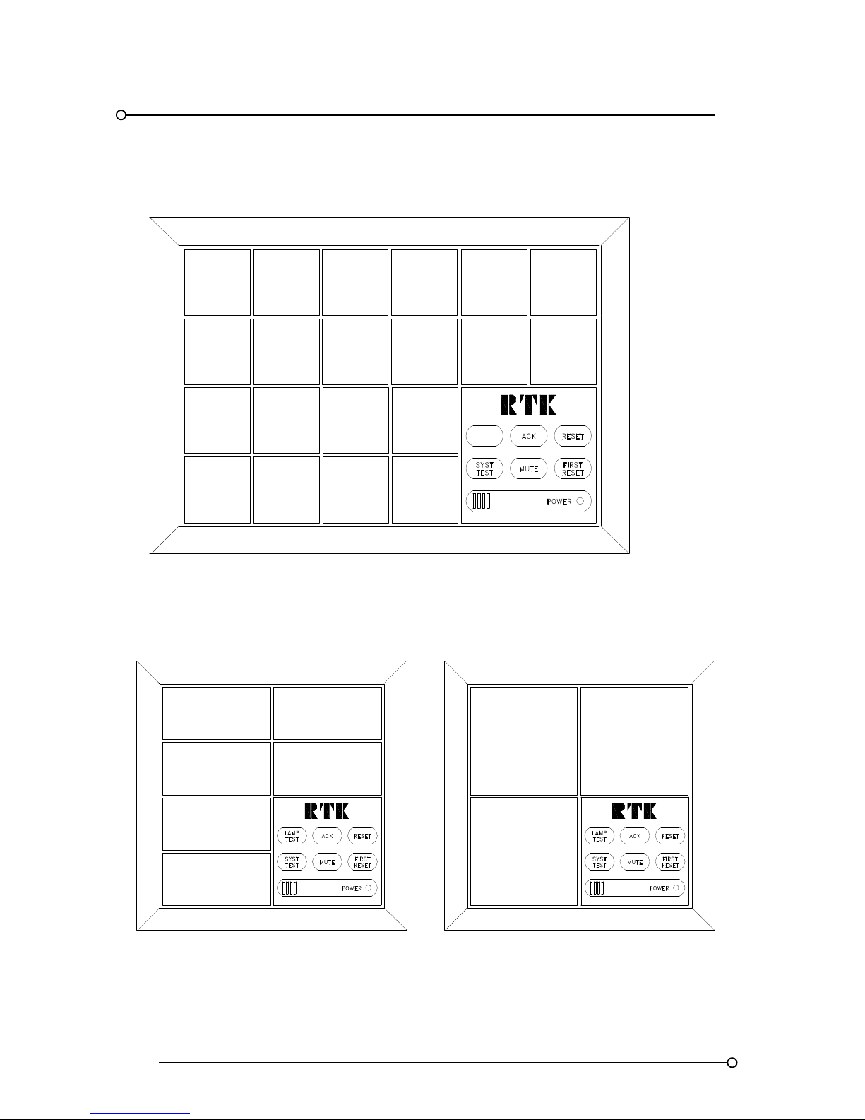
2. Front View Examples
SIX
WINDOW
COLOURS
AVAILABLE
BATTERY
LOW
VOLTS
LEVEL
TRANS
FAILURE
SMALL
WINDOW
VERSION
30 X 30 MM
NO 2
AIR COOLER
FAILURE
NO 1
AIR COOLER
FAILURE
LAMP
OR
LED
VERSIONS
SIX
LED
COLOURS
AVAILABLE
PROTECTION
TRIP
FULLY
FIELD
PROGR
MOTOR 1
HIGH
TEMP
LASER
PRINTED
FILM
LEGENDS
OPTIONAL
SERIAL
INTERFACE
CARD
MOTOR 2
HIGH
TEMP
LAMP
TEST
PLC
FAILURE
GAS
PRESSURE
LOW
Small Window Version
SIX
WINDOW
COLOURS
MEDIUM
WINDOW
VERSION
30 X 60 MM
LAMP OR LED
ILLUMINATION
LARGE
WINDOW
VERSION
60 X 60 MM
LAMP OR LED
ILLUMINATION
SIX
WINDOW
COLOURS
SIX
LED
COLOURS
LASER
PRINTED
FILM
LEGENDS
OPTIONAL
SERIAL
INTERFACE
CARD
Medium Window Version Large Window Version
Page 9
RTK Series 725 Annunciator
9
3. System Description & Features
3.1 General
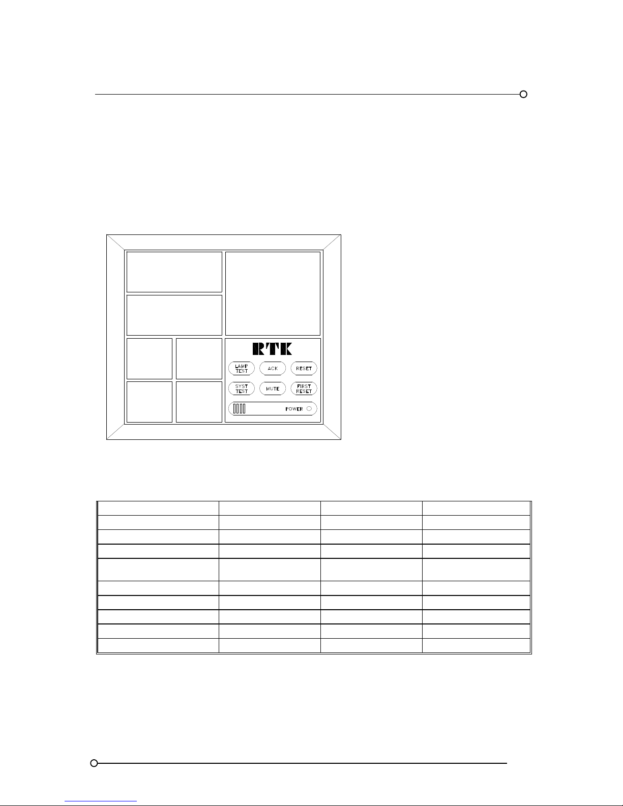
Annunciators are manufactured to meet individual customer's requirements using separate "cells"
which can be assembled in configurations from 1 to 16 cells high and 1 to 16 cells wide as required.
The finished array is “picture framed” using standard lengths of aluminium extrusion. Individual alarm
channels can be displayed in one of three sizes as shown below
Large, Medium & Small Window Sizes
LARG E
WINDOW
VERSION
60 X 60 mm
MEDIUM
WINDOW
VERSION
30 X 60 mm
SMALL
WINDOW
VERSION
30 X 30 mm
3.2 Window Colours
Each channel is equipped with its own removable bezel, which contains a clear lens, white diffuser,
coloured filter and a laser printed film legend.
Part
Small Window Medium Window Large Window
Bezel
ID-SLC-3WF-B ID-SLC-3WH-B ID-SLC-3WG-B
Clear Lens
ID-SLC-3LF ID-SLC-3LH ID-SLC-3LG
White Diffuser
ID-SLC-3PF-WH ID-SLC-3PH-WH ID-SLC- 3PG-WH
Clear filter
(used with white windows)
ID-SLC-3PF-C ID-SLC-3PH-C ID-SLC- 3PG-C
Red filter
ID-SLC-3PF-R ID-SLC-3PH-R ID-SLC- 3PG-R
Amber filter
ID-SLC-3PF-A ID-SLC-3PH-A ID-SLC- 3PG-A
Yellow filter
ID-SLC-3PF-Y ID-SLC-3PH-Y ID-SLC- 3PG-Y
Blue filter
ID-SLC-3PF-B ID-SLC-3PH-B ID-SLC- 3PG-B
Green filter
ID-SLC-3PF-GD ID-SLC-3PH-GD ID-SLC- 3PG-GD
3.3 Laser Printed Legends
Laser printed film legends are easily generated, from within Microsoft Excel, in a font style and size
to suit individual applications. A software template is available, free of charge from RTK, which allows
the user to produce film legends locally if required. Completed film legends are located between the
clear front lens of the removable window assembly and the associated coloured filter and diffuser.
Page 10
RTK Series 725 Annunciator
10
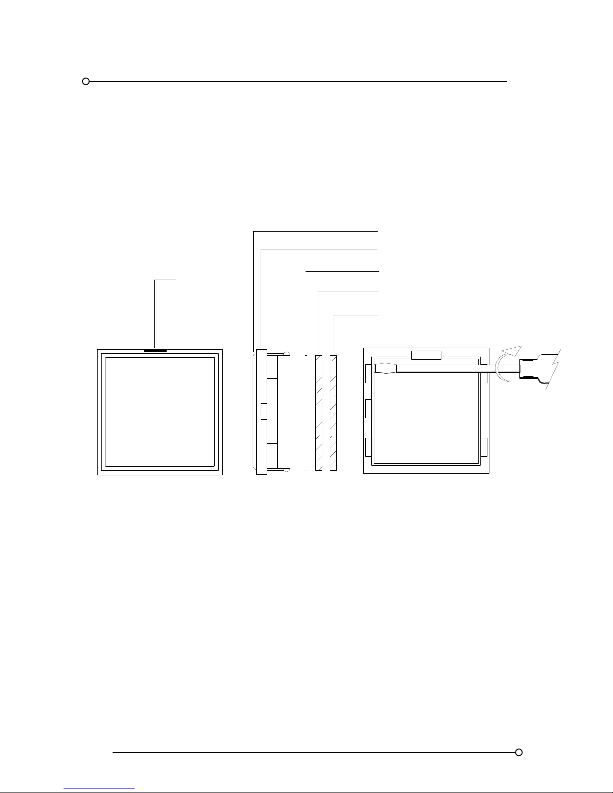
3.4 Adding Or Changing Film Legends
Each lens assembly has a small slot in the upper ridge of the surround bezel, which allows a flat
blade terminal screwdriver to be used to gently lever the assembly forward. Once the assembly has
been removed the diffuser, coloured filter and film legend can be accessed using a flat blade
screwdriver to gently lever the lens clear of the associated parts as indicated in the diagram below.
This MUST be levered on the side NOT the top or bottom
LASER
PRINTED
FILM
LEGEND
Diffuser
Coloured Filter
Film Legend
Slot to aid
lens removal
Lens
Bezel
3.5 Lamp Or LED Illumination
All units are suitable for either 28V - 10 mm wedge based lamps part no. LP-28-004 or “fit and forget”
LED assemblies part no. P725-LED-** specify colour
RD = red,
YW = yellow,
AM = amber,
BL = blue,
GN = green,
WT = white.
The LED assemblies plug into the same socket as the lamp.
Page 11
RTK Series 725 Annunciator
11
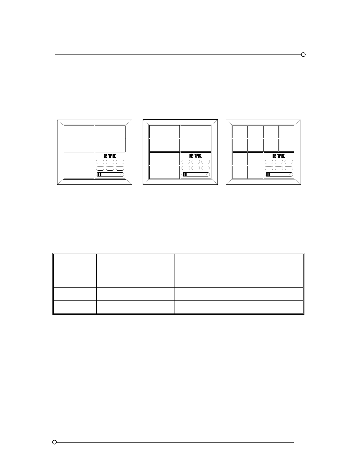
3.6 Window Numbering System
RTK have adopted the following window numbering system to aid with the location of the film legend
and the associated alarm cards. This method is used to ensure that the legend matches the functions
selected for the designated alarm.
SYSTEM
TEST
FIRST
RESET
7
MUTE
POWER
RESET
1
5
3
ACK
LAMP
TEST
RESET
FIRST
RESET
6
2
3
4
LAMP
TEST
ACK
MUTE
SYSTEM
TEST
POWER
1
5
FIRST
RESET
RESET
2
SYSTEM
TEST
POWER
MUTE
ACK
LAMP
TEST
1
3
6
8
4
2
12
10
9
11
Medium Window Version
Small Window Version
Large Window Version
3.7 Alarm Card Types
There are 4 basic types of dual channel alarm cards
PART NO DESCRIPTION USED ON
CB5674POP1
2 Channel alarm card
(Without repeat relays)
Large, medium and small window versions
Locates in the upper slot of the associated cell
CB5674POP2
2 Channel alarm card
(With repeat relay facility)
Large, medium and small window versions
Locates in the upper slot of the associated cell
CB5674POP3
2 Channel alarm card
(Without repeat relays)
Small window versions
Locates in the lower slot of the associated cell
CB5674POP4
2 Channel alarm card
(With repeat relay facility)
Small window versions
Locates in the lower slot of the associated cell
Card types are supplied suitable for operation f rom one of the following signal supply voltages 24 V,
48V, 125V or 250V. These voltages are shown on the individual alarm card and X is used to indicate
which version has been supplied. Alarm cards ar e plugged into the rear of the annunciator and once
inserted automatically connect to a pre-tested passive display motherboard.
3.8 Pushbutton / Programming Module
The pushbutton/programming module is located in the bottom right hand corner of the annunciator
when viewed from the front unless otherwise specified. It has a power-on LED, integral audible and
six pushbuttons to cover all of the possible sequence combinations. The six pushbutton are:- Lamp
Test, Functional Test, Mute, Acknowledge, Reset and First Reset
Page 12

RTK Series 725 Annunciator
12
3.9 Pushbutton / Programming Module Options
The pushbutton/programming module is normally integrally mounted within the annunciator however
if required it can be supplied as a stand alone item suitable for panel mounting, DIN-rail mounting or
wall mounting.
3.10 Fully Field Programmable
In addition to controlling the alarm sequence the pushbutton module is also used as a configuration
tool to programme the required features on the annunciator. To access the programming functions
the pushbutton fascia must be hinged down to reveal a configuration switch (labelled CONF) located
on the inner face of the assembly. Once the unit is in the CONF mode the user is able to enable or
disable a range of pre-defined features and options. The dual function pushbutton assembly allows
the user to enable any of the 25 embedded features on a per channel basis without having to remove
the power to the annunciator or to remove light-boxes, back-planes or alarm cards.
All programmed information is stored in EEPROM, with a minimum 20-year retention, giving
repeatability and reliability without the need for battery backup.
Note:- Alarm sequences will operate in accordance with any of the standard sequences defined in
the ISA publication "Alarm Sequences and Specifications S18.2 - 1979 (R1985)"
3.11 Expandability Using SI/O Cards
System expansion cards type SI/O are used in applications where either a single pushbutton /
programming module is linked to a number of alarm annunciators or when large cabinets require
additional power distribution terminals to evenly distribute the logic power. In addition to the logic
power terminals the SI/O card is also equipped with IN and OUT ribbon cable sockets to allow ribbon
cable and connectors to be used to link common control functions between annunciators.
Page 13
RTK Series 725 Annunciator
13
3.12 Sleep Mode
Sleep mode is typically used in sub station applications where the visual and audible outputs are
disabled during unmanned periods to reduce the drain on the associated station batteries.
Whilst in sleep mode the logic of the annunciator will continue to react in the normal way including
the operation of common alarm relays, watchdog relay and optional signal duplicating relays, only the
drive signals to the lamp and audible drives are disabled.
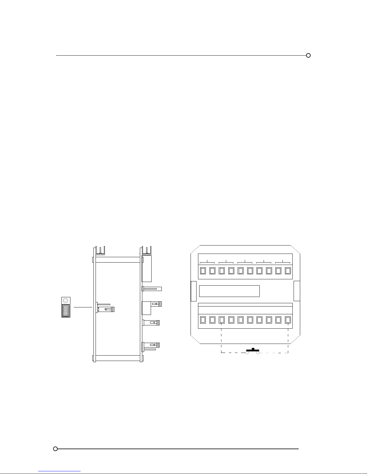
Before sleep mode can be enabled a jumper link must be pre-set on the SPR card located inside the
pushbutton / programming cell. To gain access to the SPR card first remove the back-plate on the
SPR module and then remove the associated circuit card assembly using a flat blade screw driver to
gently lever the assembly out using the white nylon pillar. Once the card has been removed locate
the 3 pin header marked FR and SP which is located on the lower of the two cards and check that
the 2 way shorting bar is in the SP position as shown below. Once the jumper has been placed into
the correct position and the card assembly placed back into the annunciator the unit can be set to
sleep mode using a remote mounting normally open maintained switch with one side of the switch
connected to +V (+24VDC) and the other side of the switch connected to terminal FR located on the
rear of the pushbutton / programming cell. Whilst the switch is maintained in the closed position the
unit will remain in sleep mode.
Note: - All normal pushbutton functions are inhibited during sleep mode to ensure that the operator
can view any alarms that occur as soon as the unit is returned to its normal operational state.
Sleep Mode Jumper Location
FR
SP
SUPPLY 24VDC
SPR
FR
OV OVC +V +VC T A R ST M
MULT
GPBGPA
HNBHNA
Side View
Assy Pt No
CB4642POP1
Sleep Mode Switch
Page 14
RTK Series 725 Annunciator
14
3.13 Automatic Mute Or Automatic Acknowledge
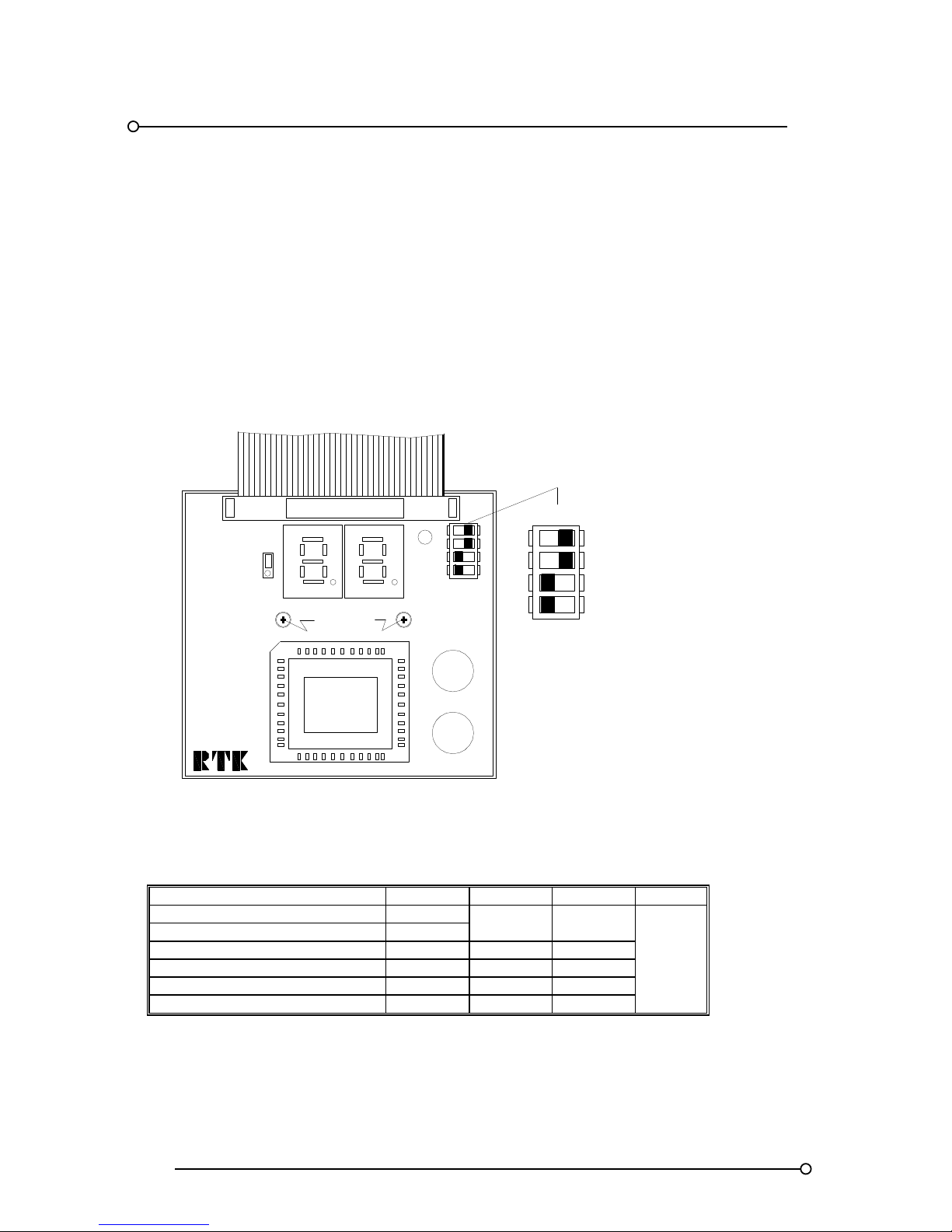
Each annunciator is equipped with an integral timer that can be enabled to allow the user to
automatically mute or acknowledge alarms after a pre-set time delay. To set the automatic mute or
acknowledge feature the pushbutton / programming module must be hinged down by inserting a
small flat blade screw driver into the recess on the upper face of the associated surround bezel and
gently levering the pushbutton assembly forward to reveal the information plate which is visible on
the inside face of the module. The two pozidrive screws and washers in the centre of the plate should
be removed to allow access to DIL switch SW7, which is used to set the unit to automatically silence
or acknowledge and to set the required time delay.
Auto Mute / Ack Delay Switch Location (Information Plate Removed)
A4219-*
Posidrive
screws
CB4072POP
ON
SW7
ON OFF
1
OFF
3
2
4
SW7
Automatic Acknowledge or Silence Time Selection
FUNCTION SW7-1 SW7-2 SW7-3 SW7-4
Automatic acknowledge ON
UNUSED
Automatic mute OFF
Disable automatic timer OFF OFF
Enable 1 minute time delay ON OFF
Enable 4 minute time delay OFF ON
Enable 8 minute time delay ON ON
Page 15
RTK Series 725 Annunciator
15
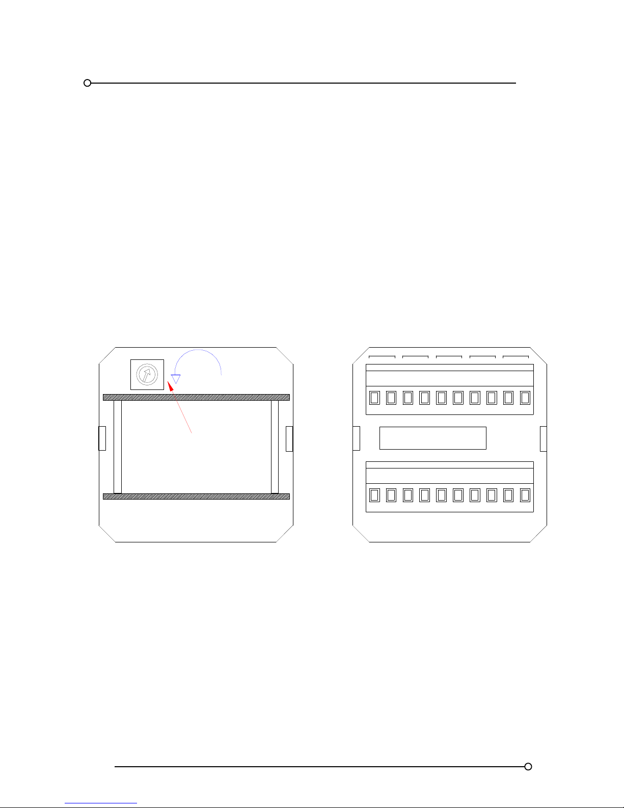
3.14 Integral Audible Alarm
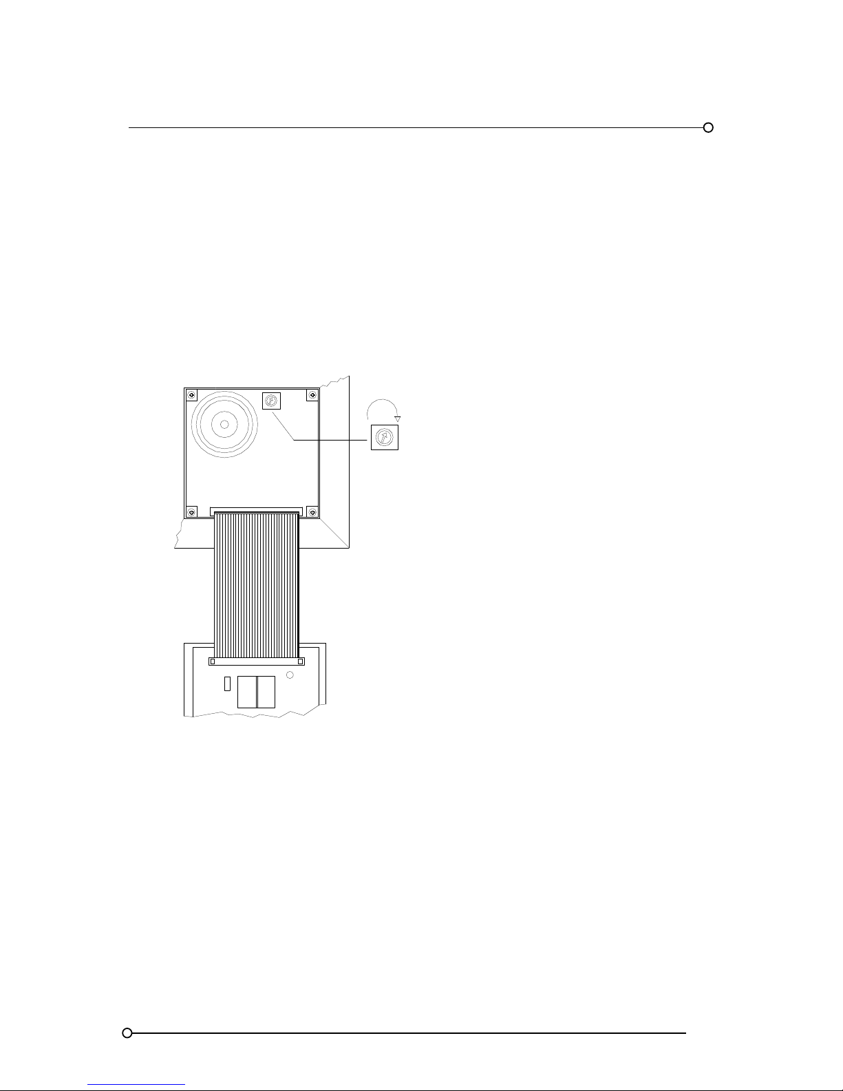
Each annunciator is equipped with an internal 3.5kHz 95dB(A) audible located behind the integral
pushbutton module. The audible is supplied with an adjustable volume control using a single turn
potentiometer. The potentiometer can be accessed by hinging down the integral pushbutton module
using a small flat blade screwdriver in the slot of the surround bezel. The potentiometer is located in
the top right hand corner of the cell as shown below. On systems with channels configured to
activate either the urgent or non-urgent audible relays it is important to note that the internal audible
will only operate on channels set to operate the critical audible relay HNA (see Function F23).
Integral Horn Volume Adjustment Location
CAL
FUNCTION
STATUS
Internal audible
volume adjustment
Increase
Page 16
RTK Series 725 Annunciator
16
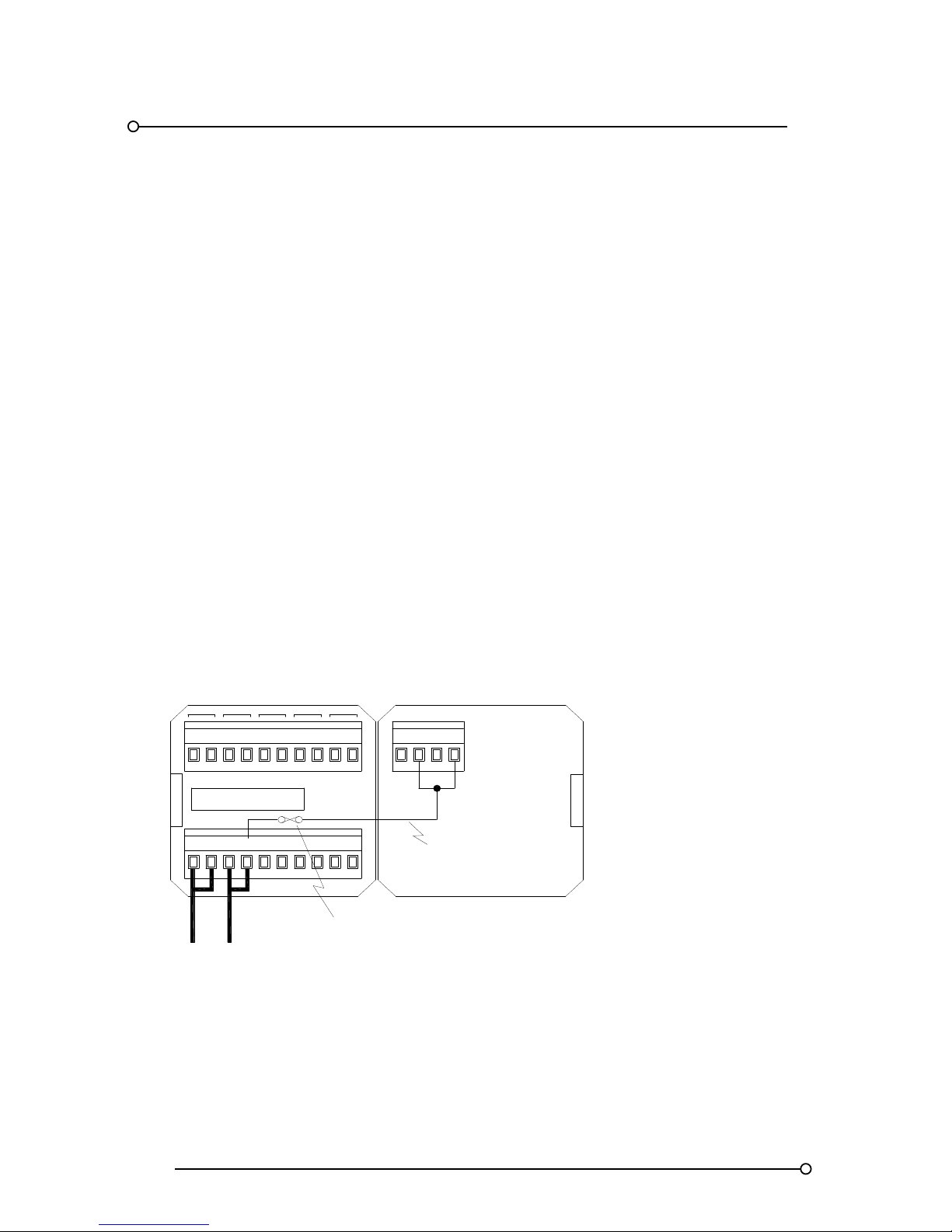
3.14a Horn adjustment on Remote Pushbutton / Programming Modules
On P725 Systems supplied with Remote Pushbutton / Programme Modules the horn adjustment
potentiometer is located in an alternative position to that shown above. The potentiometer can only
be accessed from the rear of the Pushbutton cell using the following procedure.
1. Remove Power From the annunciator
2. Remove the t wo green terminal blocks which provide customer terminations on the rear of
the pushbutton cell.
3. Remove the plastic protection cover on the rear of the pushbutton cell
4. The potentiometer is now accessed on the inside face of the pushbutton cell and can be
adjusted as required
Once adjustment has been made the plastic cover and customer terminal blocks can be re-fitted and
the power can be applied to check the volume level.
HNB
SUPPLY 24VDC
OV OVC
+V
HNA
ST
+VC
T A R
SPR
FRM
GPBGPA
MULT
REAR VIEW OF PUSHBUTTON CELL WITH
TERMINALS AND COVER REMOVED
REAR VIEW OF COVER / TERMINALS
Increase
HORN VOLUME
ADJUSTMENT
Page 17
RTK Series 725 Annunciator
17
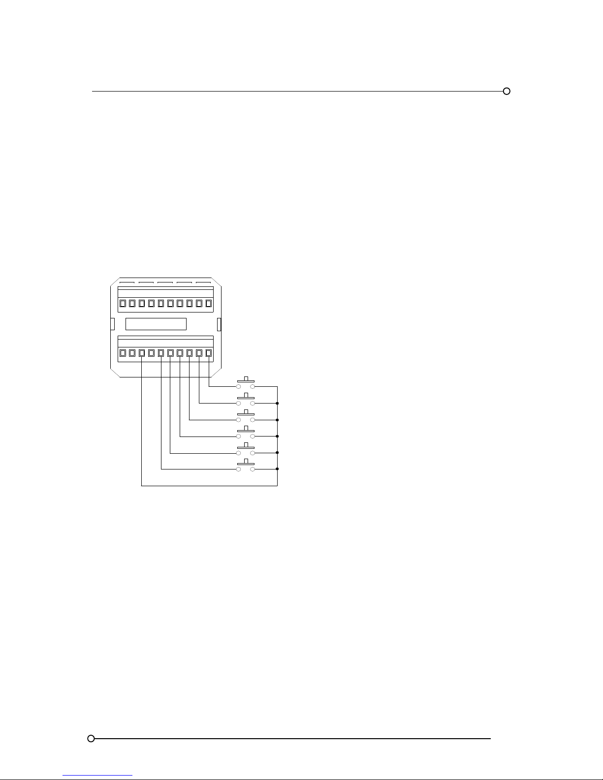
3.15 Remote Pushbutton Inputs
Remote pushbuttons can be connected to the P725 SPR module either in place of or in addition to
the integral pushbuttons or to allow multiple annunciators to share common pushbuttons for example
a common mute pushbutton mounted in the operator desk console. The pushbuttons should be of
the normally open, momentary type and it is recommended that if long cable runs are required
through electrically noisy environments a screened cable is used with the screen connected to a
suitable instrument earth at one end only. Please note:- When the annunciator is in the configuration
mode with the CONF switch in the ON position all integral or remote pushbutton inputs are disabled
until the unit has been returned to its normal operating state.
Remote Pushbutton Wiring
SUPPLY 24VDC
SPR
HNA HNB
GPA GPB
MULT
FIRST RESET
MUTE
SYSTEM TEST
RESET
ACKNOW LEDGE
LAMP TEST
OV OVC+V +VC
T A RSTM FR
Please note:-
The common return for the remote pushbutton inputs is always +V (+24VDC) on all versions.
IMPORTANT:- +VC should not be used as in some applications this terminal is used to provide the
connection for High Voltage signal input power @ 48VDC, 125VDC, 120VAC or 240VAC.
3.16 Terminations
All active cells within the annunciator are provided with quick disconnect (2) part pluggable, rising
clamp, terminals capable of accepting up to 2.5mm² cable. In the unlikely event that a card fails the
associated field wiring can remain connected and the terminal temporary unplugged to allow removal
and replacement of the associated card.
3.17 Failsafe Mode
All relays are configured in their default setting as energised. The relays will de-energise on trip or in
the case of a power failure.
Page 18
RTK Series 725 Annunciator
18
4. Inputs
4.1 Optically Coupled Inputs
All alarm inputs are provided with fully isolated inputs using optical couplers and a transient filter is
built into the input circuitry so that low voltage interference will be ignored.
4.2 Standard Input Configuration
The standard Series 725 annunciator can be set to operate from volt free signal contacts that are
either normally open or normally closed.
Setting function F1 to the off state conditions the input to accept a normally open contact.
Setting function F1 to the on state conditions the input to accept a normally closed contact.
Please note:- when using the Customer adjustable response time options AD* on P725 Annunciator
supplied after March 2009 Function F1 should always be set to “OFF” and switch SW2 should be
used to set the Input to normally open or normally closed as described in Section 24 of this manual
4.3 Signal Supply Voltage
On standard units an internally fused 24vdc signal supply (+VC), derived from the 24VDC logic
supply (+V), is distributed to all of the common terminals marked “C” which are located to the right of
each signal input terminal as typically shown below.
Typical Signal Supply Voltage Distribution
Logic supply
Intern ally di stributed
signal supply voltage
Intern al
1A signal
supply fuse
OVCOV
+V
+VC
RT A
ST
M FR
SPR
MULT
SUPPLY 24VDC
HNA HNB
GPBGPA C1 C2
+24V
OV
Page 19

RTK Series 725 Annunciator
19
4.4 Input Voltage Options
Annunciators can be supplied suitable for connection to direct powered inputs as an option with the
signal supply voltage being supplied from outside the annunciator by others. In this application the
logic supply (OV and +V) and signal supply (OVC and +VC) inputs located on the SPR module are
independently wired and fully isolated from each other.
OPTION CODE
VOLTAGE
Standard 24V AC/DC
FC048 48V AC/DC
FC125 125V AC/DC
FC250 250V AC/DC
4.5 Input Time Delay – Option AD*
As an option each channel can be provided with a potentiometer, which allows the user to select a
time delay to prevent the alarm from occurring unless it has been present for a pre-defined period.
Option AD1 = Adjustable Delay Range 5 – 50 ms
Option AD2 = Adjustable Delay Range 20ms - 2 seconds
Option AD3 = Adjustable Delay Range 5ms – 5 seconds
4.6 Input Wiring Segregation
Field contacts are often great distances from the annunciator it is therefore advisable to run the
contact cables separately from circuits carrying heavy currents and/or high voltages to minimise the
affects of induced voltages.
4.7 No Master Module
Each dual channel alarm card is equipped with a dedicated application specific integrated circuit
(ASIC). System control is automatically allocated to one of the alarm cards during power on and if
this card is removed, damaged or fails (apart from catastrophic failure), another card will
automatically take over the common control functions. This method of operation eliminates the need
for a traditional style common services/control module and removes common failure points thus
increasing reliability.
Page 20
RTK Series 725 Annunciator
20
5. Outputs
5.1 Common Outputs
All series 725 annunciators are equipped with five common output relays located on the upper card
of the SPR module. (Part no CB4642POP1).
As standard all five relays are factory set to be normally energised and will de-energise when
activated.
Each relay is equipped with volt free contacts for customer use, which can be selected to be either
normally open or normally closed in the non-alarm state per the following table.
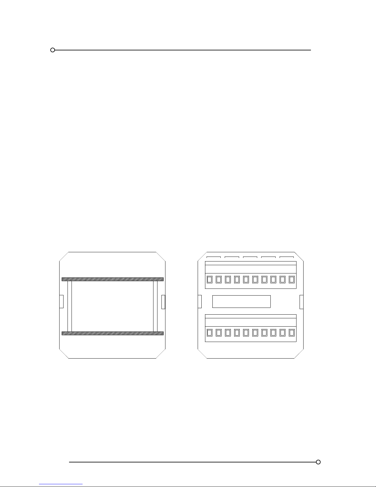
To change any of the settings the relay card must be removed from the system as described
below
1. Remove Power From the annunciator
2. Remove the t wo green terminal blocks which provide customer terminations on the rear of
the pushbutton cell.
3. Remove the plastic protection cover on the rear of the pushbutton cell by releasing the tabs
on either side of the cover
4. Remove the t win card assembly from the rear of the unit. (A flat blade screwdriver can be
used to gently lever the assembly from the cell by placing the blade under the white stand
off pillars and the side of the cell).
HNB
SUPPLY 24VDC
OV OVC+V
HNA
ST
+VC
T A R
SPR
FRM
GPBGPA
MULT
REAR VIEW OF COVER / TERMINALS
REAR VIEW OF PUSHBUTTON CELL WITH
TERMINALS AND COVER REMOVED
Page 21
RTK Series 725 Annunciator
21
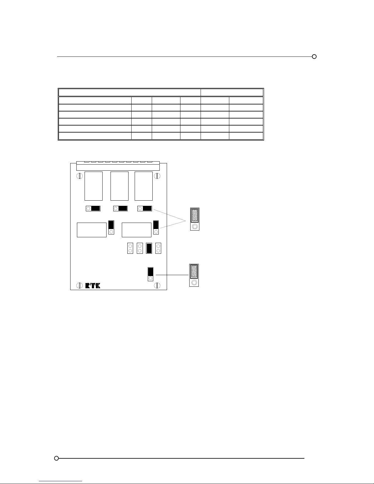
SPR Card Showing Relay And Jumper Locations
CONTACT STATE
FUNCTION
REF.
RELAY
LINK
OPEN
CLOSED
Critical horn relay HNA RL1 LK1 N/O N/C
Non critical horn relay HNB RL2 LK2 N/O N/C
Critical group relay GPA RL3 LK3 N/O N/C
Non-critical group relay GPB RL4 LK4 N/O N/C
Multifunctional relay MUL RL5 LK5 N/O N/C
Pt No CB4642POP1
N/C
RL2 - HNB
HORN RELAY
RL3
GPA
GROUP
RELAY
RL5
MULT.
FUNCT.
RELAY
LK5
RL4 - GPB
GROUP RELAY
N/O
LK4
N/O
N/C
N/C
N/O
LK3
1ST
COMM'S
STD
LK10
RBHGP WD
COMM'S
STD
CONTACT SET
NORMALLY CLOSED
NORMALLY OPEN
RL1
HNA
HORN
RELAY
LK6
LK2
LK8
LK7
LK9
N/O
LK1
N/C
N/O
N/C
N/O
N/C
5.2 Critical Horn Relay - HNA
When an alarm occurs the horn relay will change state and remain in the alarm condition until the
mute or ack pushbutton has been pressed. Each channel can be set to operate the critical horn relay
as required. Please note:- Channels set to operate the critical horn relay will also operate the integral
audible alarm.
5.3 Non-Critical Horn Relay - HNB
When an alarm occurs the relay will change state and remain in the alarm condition until the mute or
ack pushbutton has been pressed. Each channel can be set to operate the non- critical horn relay as
required. Please note:- Channels set to operate the non-critical horn relay will not operate the integral
audible alarm.
Page 22
RTK Series 725 Annunciator
22
5.4 Critical Group Relay - GPA
When an alarm occurs the relay will change state and remain in the alarm condition until all alarms in
the group have returned to normal and the logic has been reset. Each channel can be set to operate
the critical group relay as required.
5.5 Critical Group Relay - GPB
When an alarm occurs the relay will change state and remain in the alarm condition until all alarms in
the group have returned to normal and the logic has been reset. Each channel can be set to operate
the non-critical group relay as required.
5.6 Reflash Critical Group Relay - GPA
When an alarm occurs in the critical group the relay will change state and if reflash is set any
subsequent alarm occurring in the same group will cause the relay to drop out for 0.5 seconds. Each
channel can be set to reflash the critical group relay as required.
5.7 Reflash Non-Critical Group Relay - GPB
When an alarm occurs in the non-critical group the relay will change state and if reflash is set any
subsequent alarm occurring in the same group will cause the relay to drop out for 0.5 seconds. Each
channel can be set to reflash the non-critical group relay as required.
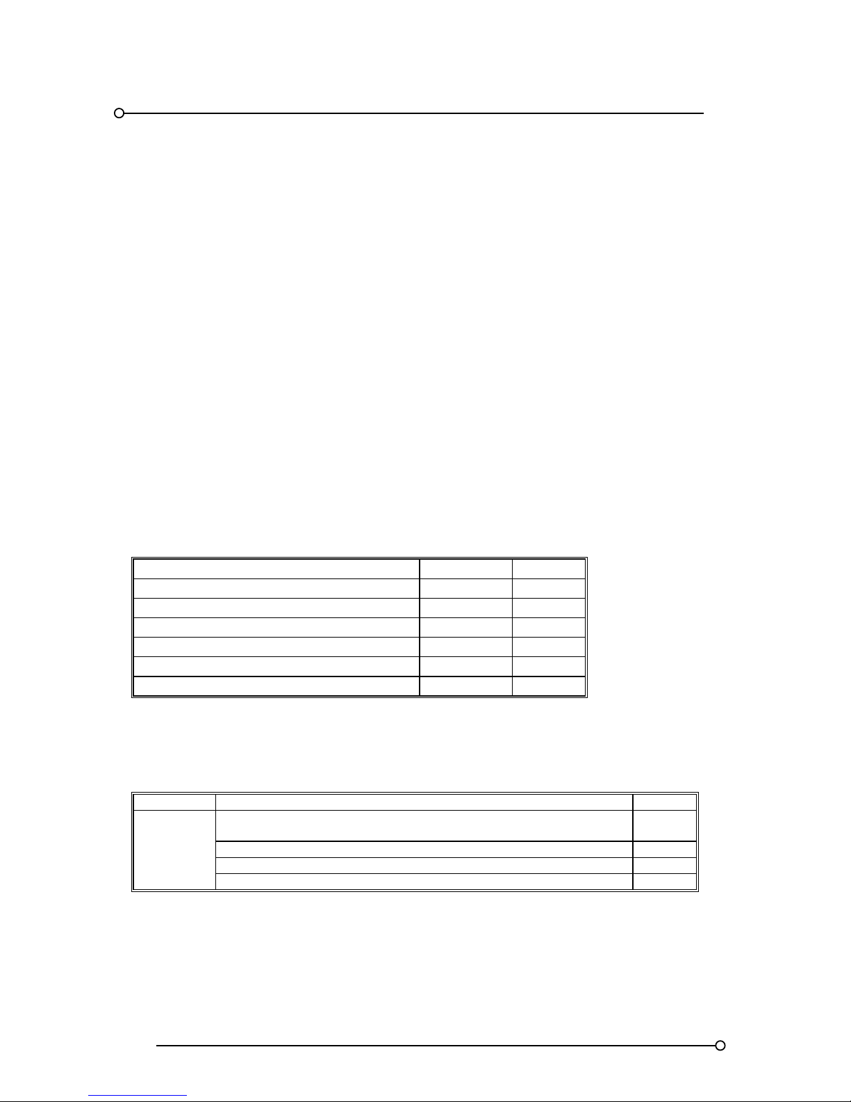
5.8 Common Relay Function Codes
FEATURE DESCRIPTION FUNCTION SETTING
Critical horn relay enable F23 ON
Non-critical horn relay enable F24 ON
Critical group relay enable F21 ON
Non-critical group relay enable F22 ON
Reflash critical group relay enable F8 ON
Reflash non-critical group relay enable F9 ON
5.9 Multi-Function Relay Operating Modes
The multi-function relay RL5 can be configured to act in different ways to suit particular applications
by selecting one of the features detailed below and placing the shorting bar on the associated LK*
jumper.
RELAY FUNCTION LINK
RL5
RTG = Summary group relay (Common relay which acts as a
summary relay of the GPA & GPB relays)
LK7
RB = Ringback horn relay LK8
FU = First up relay LK6
WD = Power On – Watchdog relay LK9
When the shorting bar is set to LK7 the MUL relay will act as a summary group relay, therefore any
alarm in the system set to operate either the group A or group B common alarm relay will also
operate the summary group relay
Page 23

RTK Series 725 Annunciator
23
6. Technical Specifications
FEATURES
DETAILS
Input type
Each channel can be set to operate from either a normally open or normally
closed contact as required
Standard version
Signal voltage
24VAC/DC 9V to 33V
Optional versions
Direct voltage inputs
48VAC/DC 19 to 70V
110VAC/DC 72 to 135V
220VAC/DC 141 to 270V
Contact resistance
Normally Closed 20k Ohm maximum series resistance
Normally Open 50k Ohm minimum parallel resistance
Contact current Typically 3mA
Response time Typically 25ms (alternatives available on request)
First up 5ms Discrimination
Input protection
Reverse polarity of the input supply
Application of a 1000V megger tester between input and earth
Input Delay
Options exist for fixed or adjustable input time delays.
Adjustable delays
AD1= user selectable from 5 to 50ms
AD2 = user selectable from 20ms to 2 seconds
AD3 = user selectable from 5ms to 5 seconds
Internal audible
3.5 kHz @ 95db(A) At 1 Metre distance complete with volume adjustment
(Functions as a slave of the critical horn circuit)
Common relays
Contacts rated 2A@24VDC, 0.4A @120VAC resistive, 0.5A @ 125VDC
resistive. Maximum voltage 220VDC (250VAC)
Individual channel
Repeat relay option
Each alarm can be supplied with an individual repeat relay with a
changeover contact rated 2A@24VDC, 0.4A @120VAC resistive, 0.5A @
125VDC resistive. Maximum voltage 220VDC (250VAC).
Communication option
The unit can be supplied with RS485 bi-directional
Serial communications baud rate: 4800 or 9600 / Parity: odd or
even / protocol: Modbus ASCII or RTU (user selectable)
Window sizes (H x W) Small 30 x 30 mm Medium 30 x 60 mm Large 60 x 60 mm
Window colours Red, Amber, Yellow, Green, White, or Blue
Illumination
10 mm 50mA glass wedge filament lamps (Typ. 14,000 Hours) or “fit &
forget” LED assembly which fits into the same lamp socket
Small windows use single bulbs or LED arrays
Medium windows use dual bulbs or LED arrays
Large windows use quad bulbs or LED arrays
Alarm legends
Laser printed film legends plus software template if required
EMC compliance
IMMUNITY TO BS EN50082-2:1995 EMISSIONS TO BS EN50081-2:1994
LVD compliance
BS EN61010 1:1993
Operating temp.
-20oC to +50oC (lamp version)
-20oC to +60oC (LED version)
Storage
Temp.
-20oC to +80oC
Humidity
0 to 95% RH Non Condensing
Protection
Front of panel IP41 Rear of panel IP20
Optional covers or wall
mounting enclosures
IP54 to IP67 on request
Terminals
Rising clamp type terminals. Maximum cable size 2.5mm²
Weight Approx. 0.3kg per module
Page 24
RTK Series 725 Annunciator
24
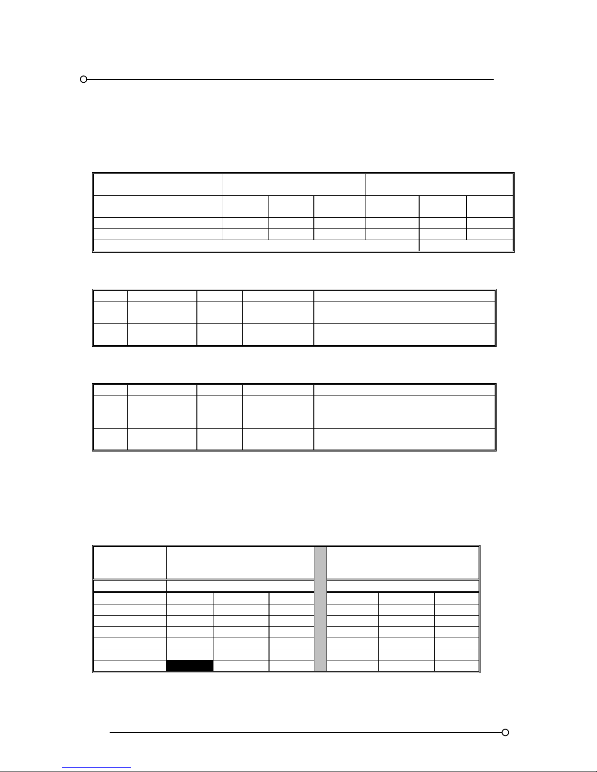
6.1 General
Supply voltage:- 24VDC (19 to 28VDC)
Quiescent supply current 9mA per channel @ 24VDC
ALARM STATE CURRENT
PER CHANNEL
FILAMENT LAMP
VERSION
FIT AND FORGET L.E.D.
VERSION
Window size
Small
window
Medium
window
Large
window
Small
window
Medium
window
Large
window
Standard systems 45 mA 90 mA 180 mA 20 mA 40 mA 80 mA
Systems with repeat relays 55 mA 100 mA 190 mA 30 mA 50 mA 90 mA
Pushbutton module plus common relays and integral audible alarm 100 mA Extra
6.2 Fuse Details - SPR Module
FUSE FUNCTION RATING TYPE PURPOSE
F1 Logic supply 10A/T 20 x 5 mm Protects the logic supply within the alarm
annunciator
F2 Signal supply 1A/F Surface mount Protects the signal supply voltage feed to
the common “C” terminals
6.3 Fuse Details - S/O Module
FUSE FUNCTION RATING TYPE PURPOSE
F1 Logic supply 5A/T 20 x 5 mm
Protects additional 24VDC supply feed
when current required exceeds one SPR
module
F2 Signal supply 1A/F Surface mount Protects the signal supply voltage feed to
the common “C” terminals
6.4 Suitable Power Supplies
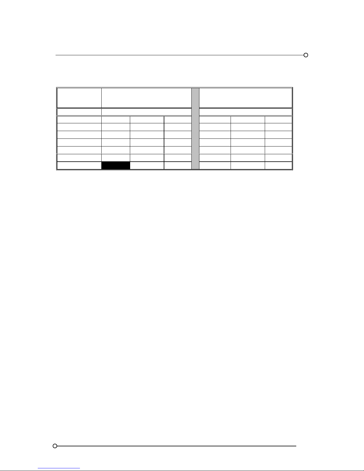
The table below indicates the maximum numbers of alarm channels that can be connected to a
standard power supply from the RTK range of products. Each PSU provides a 24VDC output for use
as the logic voltage to the annunciator.
6.5 P725 Annunciator Standard Versions
PSU RATING
LED VERSION
LAMP VERSION
@ 24VDC WINDOW TYPE WINDOW TYPE
CURRENT (A) SMALL MEDIUM LARGE SMALL MEDIUM LARGE
1.1 34 20 11 18 10 5
1.8 58 34 19 31 17 9
2.5 82 49 27 44 24 13
4.5 151 89 49 81 44 23
6.5 220 130 72 118 64 34
12.5 253 139 229 125 65
Page 25
RTK Series 725 Annunciator
25
6.6 P725 Annunciator Fitted With The Repeat Relays Per Channel Option
PSU RATING
LED VERSION
LAMP VERSION
@ 24VDC WINDOW TYPE WINDOW TYPE
CURRENT (A) SMALL MEDIUM LARGE SMALL MEDIUM LARGE
1.1 25 17 10 15 9 5
1.8 43 29 17 26 15 8
2.5 61 40 24 37 21 12
4.5 113 74 44 69 40 22
6.5 164 108 64 100 58 32
12.5 210 125 193 112 62
Larger PSU or multiple PSU can be used if required
Page 26

RTK Series 725 Annunciator
26
7. Mechanical Details
7.1 P725 Overall And Cut Out Dimensions
CABINET DIMENSIONS IN MM
HIGH
X
WIDE
Cells Overall Cut-Out Cells Overall Cut-Out
1 84 74 1 84 74
2 144 134 2 144 134
3 204 194 3 204 194
4 264 254 4 264 254
5 324 314 5 324 314
6 384 374 6 384 374
7 444 434 7 444 434
8 504 494 8 504 494
9 564 554 9 564 554
10 624 614 10 624 614
11 684 674 11 684 674
12 744 734 12 744 734
13 804 794 13 804 794
14 864 854 14 864 854
15 924 914 15 924 914
16 984 974 16 984 974
Please note:- The cut out tolerance should be with ±2mm. Annunciator depth is 145mm
Caution
The above table indicates the dimensions based on the number of cells high X cells wide this should
not be confused with the number of alarm windows high and wide which can vary depending on
required window size. i.e. There would be :- 1 x Large window per cell, 2 x Medium windows per cell,
or 4 x Small windows per cell.
7.2 System Capacity
The maximum number of alarms available within a single annunciator is dependent on the maximum
number of cards the system can address. This is fixed at 128 two channel cards, making the
maximum system size for all window sizes 256 channels.
In applications where a number of separate annunciators are linked together to form a common
system the max capacity for the whole system will remain at 256 alarms.
Page 27
RTK Series 725 Annunciator
27
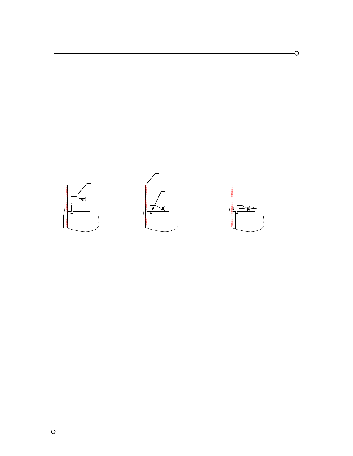
7.3 Panel Mounting Clamps
The annunciator is shipped with the panel mounting clamps fitted to the sides of the unit these must
be removed to allow the unit to be placed in the panel cut out and secured from behind. Once the
unit has been placed in the panel cut out the panel clamps and screws are used to secure the unit as
shown below. Maximum panel thickness 5mm
Securing the Annunciator into the panel
PANEL CLAMP
WITH SCREW
PAN E L
AS SCREW TIGHTENS
CLAMP IS SECURED
TO FRAME SECTION
SIT HOOK ON CLAMP
INTO GROOVE IN FRAME
1 2 3
Page 28

RTK Series 725 Annunciator
28
8. Alarm Sequences
8.1 Summary
Each channel within the annunciator can be set to operate in a pre-defined manner in accordance
with internationally recognised standards ISA-S18.1 1979 (R2004) alarm sequences. Typically when
an alarm occurs the associated window will flash and the operator uses specific pushbuttons to
control the audible alarm and associated lamps or LED’s:-
Test is used to test the lamps or optional LED’s only by illuminating them in a steady on state for as
long as the pushbutton is pressed.
System Test is used to simulate a full functional test therefore all windows and horn circuits will
operate in accordance with the selected sequence and additional pushbuttons will need to be
pressed to step through the sequence and return the unit to its normal state.
Mute is used to silence the audible but allow the associated alarm window to continue to operate
as per the selected sequence.
Acknowledge will silence the audible alarm and change the state of the associated window in
accordance with the selected sequence.
Reset will return the alarm to the normal off state only if the unit has been acknowledged and the
associated alarm contact has returned to its normal non-alarm state.
First Reset is used after acknowledge to reset the flash sequence on the first alarm to occur
within a defined group of alarms. Once f irst reset has been pressed the next alarm to occur within the
group will flash at the first-up alarm rate.
8.2 Audible Alarm Grouping
Each channel within the annunciator can be set to operate the audible alarm relays as follows:-
1. Critical horn relay
2. Non critical horn relay
3. Both the critical and non critical horn relay
4. Neither of the horn relays (Typically status only alarms)
Please note channels, which are set to operate the critical horn relay, will automatically operate the
internal piezo buzzer.
8.3 Ringback Audible
When using ISA “R” ringback sequence the MULT relay can be set to operate as a ringback audible
if required. The ringback audible would normally have a distinct tone to allow the operator to
distinguish between a standard alarm and an channel that has returned to normal and needs to be
reset.
Page 29

RTK Series 725 Annunciator
29
9. Additional Features
9.1 Automatic Reset
Once an alarm has been acknowledged and its input has returned to its normal state the alarm can
be set to automatically reset without the operator having to press the reset pushbutton.
9.2 Non-Latch Sequence (No Lock-In)
Alarms can be set to non lock-in, which allows the alarm to automatically return to the non alarm
( off ) state as soon as the signal input returns to normal.
9.3 Reflash Feature
Input reflash is used to inform the operator that an acknowledged alarm has returned to normal and
re-alarmed whilst waiting for reset.
9.4 Ringback Sequence
Ringback sequence is used to inform the operator, both visually and audibly, that an alarm condition
has cleared and the channel can be reset to its normal off state. When a contact returns to normal
the associated window will flash at approx ½ the speed of a normal alarm and the audible alarm will
sound. This identifies the specific alarm and allows the operator to reset as soon as the process is
normal. As an option the MULT relay can be used to drive a 2nd audible set to a different tone to the
main audible for use as a ringback audible. Please note ringback cannot function if a channel is set
to auto- reset or non lock- in.
9.5 Two Pushbutton Operation
In certain circumstances using remote pushbuttons, it may be desirable to use only two pushbuttons:
reset and lamp test. The reset pushbutton is used to acknowledge an alarm if the contacts are in the
alarm condition and to reset it if the contacts are clear.
9.6 First-Up Sequences
When monitoring devices with interlinked functions such as a turbine or compressor it is often
important to know the specific alarm that occurred first, as it will invariably result in cascade of
secondary alarms. This allows the operator to focus on the root cause of failure and therefore limits
the downtime and associated costs. This is achieved by having the first-up alarm flashing in a
different manner compared to the subsequent alarms. Four different first-up sequences are available
F0, F1, F2 and F3 as detailed below and in the following sequence tables.
F0 The standard mode adopted by RTK Instruments, which indicates the first-up alarm by flashing at
twice the rate of subsequent alarms.
F1 In this mode subsequent alarms appear in the acknowledged state, hence they do not flash. The
audible device does not operate when subsequent alarms occur, unless still operating from the
first alarm. The acknowledge pushbutton will reset the first-up indication.
F2 In this mode all subsequent alarms do not flash, they will however operate the audible device.
The acknowledge pushbutton will reset the first-up indication.
F3 In this mode initial alarms appear with an intermittent flash rate and subsequent alarms flash at a
steady rate. On acknowledge subsequent alarms revert to the steady on state and only the first
alarm continues to flash at a slower rate.
Please note auto reset and non lock- in functions are not recommended when using first up
sequences as the true sequence of events cannot be guaranteed.
Page 30
RTK Series 725 Annunciator
30
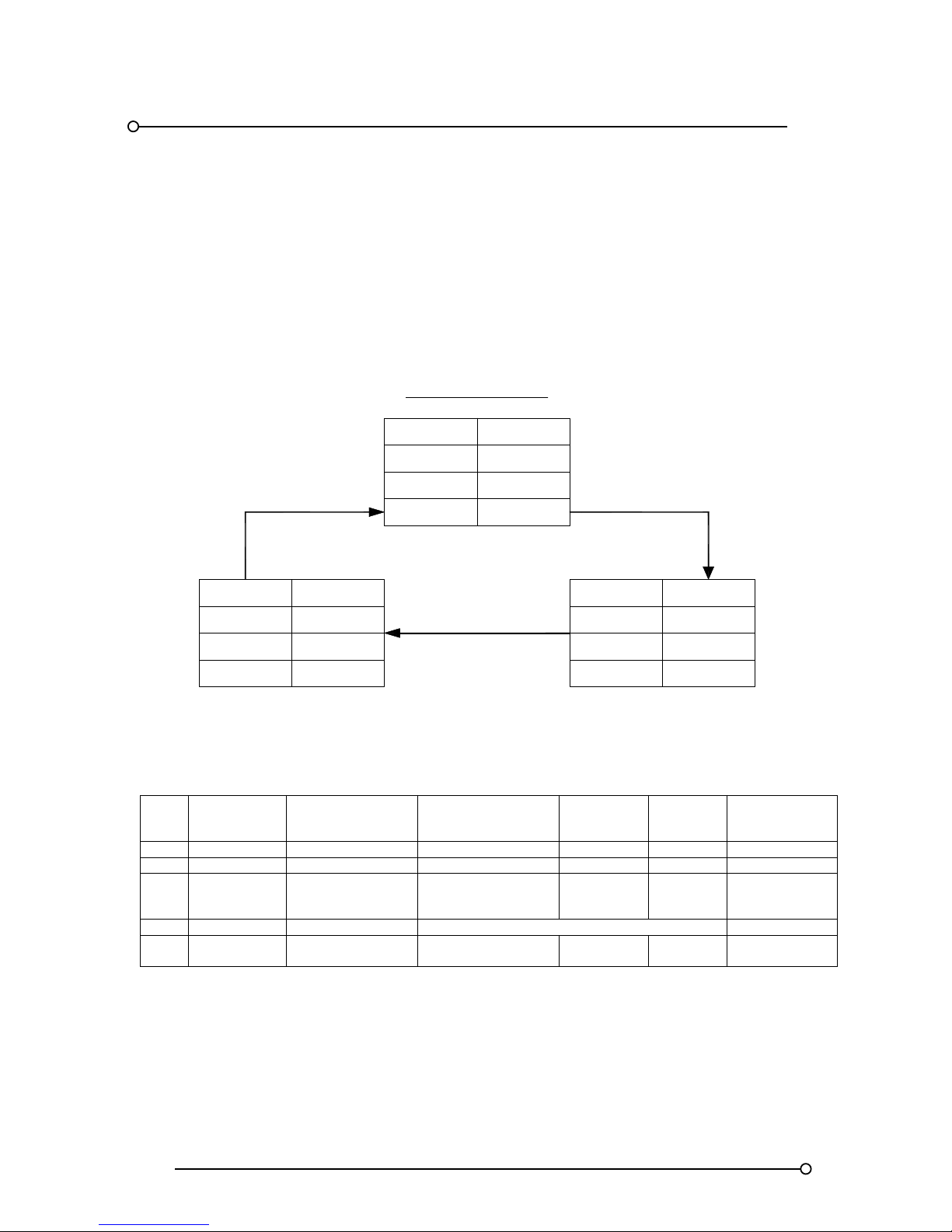
10. Sequence Configuration and Tables
Each pair of alarm channels can be configured to suit the operating sequence required, as listed in
the ISA publication "Annunciator sequences and specifications" S18.1 1979.(R2004). Systems can
be configured with different features on each individual channel and there is no need to switch the
power off when making these changes. Different operating modes can be selected using the integral
Pushbutton/Programming module as described later in this manual. The following tables show the
most commonly used examples.
10.1 ISA-Sequence M - Manual Reset
SEQUENCE TABLE
LINE
PROCESS
CONDITION
PUSHBUTTON
OPERATION
SEQUENCE STATE
VISUAL
DISPLAY
ALARM
AUDIBLE
DEVICE
REMARKS
1 NORMAL NORMAL OFF SILENT
2 ABNORMAL ALARM FLASHING AUDIBLE LOCK-IN
3
ABNORMAL
OR NORMAL
ACKNOWLEDGE ACKNOWLEDGED ON SILENT
MANUAL
RESET
REQUIRED
4A ABNORMAL RESET TO LINE 3
4B NORMAL RESET NORMAL OFF SILENT
MANUAL
RESET
SEQUENCE FEATURES
1. ACKNOWLEDGE, RESET AND TEST PUSHBUTTONS
2. ALARM AUDIBLE DEVICE
3. LOCK-IN OF MOMENTARY ALARMS UNTIL ACKNOWLEDGED
4. THE AUDIBLE DEVICE IS SILENCED AND FLASHING STOPS WHEN ACKNOWLEDGED
5. MANUAL RESET OF ACKNOWLEDGED ALARM INDICATIONS AFTER PROCESS CONDITIONS
RETURN TO NORMAL
6. OPERATION TEST
NORMAL
OFF
NORMAL
SILENT
SEQUENCE DIAGRAM
SEQUENCE ISA M
(MA N U A L R E S E T )
VISUAL
PROCESS
VISUAL
AUDIBLE
ON
SILENT
ACKNOWLEDGED
ACKNOWLEDGE
RESET
WHILE NORMAL
AUDIBLE
PROCESS
ABNORMAL
PROCESS
VISUAL
AUDIBLE
FLASHING
AUDIBLE
ALARM
TO
ABNORMAL
OR NORMAL
ABNORMAL
OR NORMAL
SEQUENCE
SEQUENCESEQUENCE
Page 31
RTK Series 725 Annunciator
31
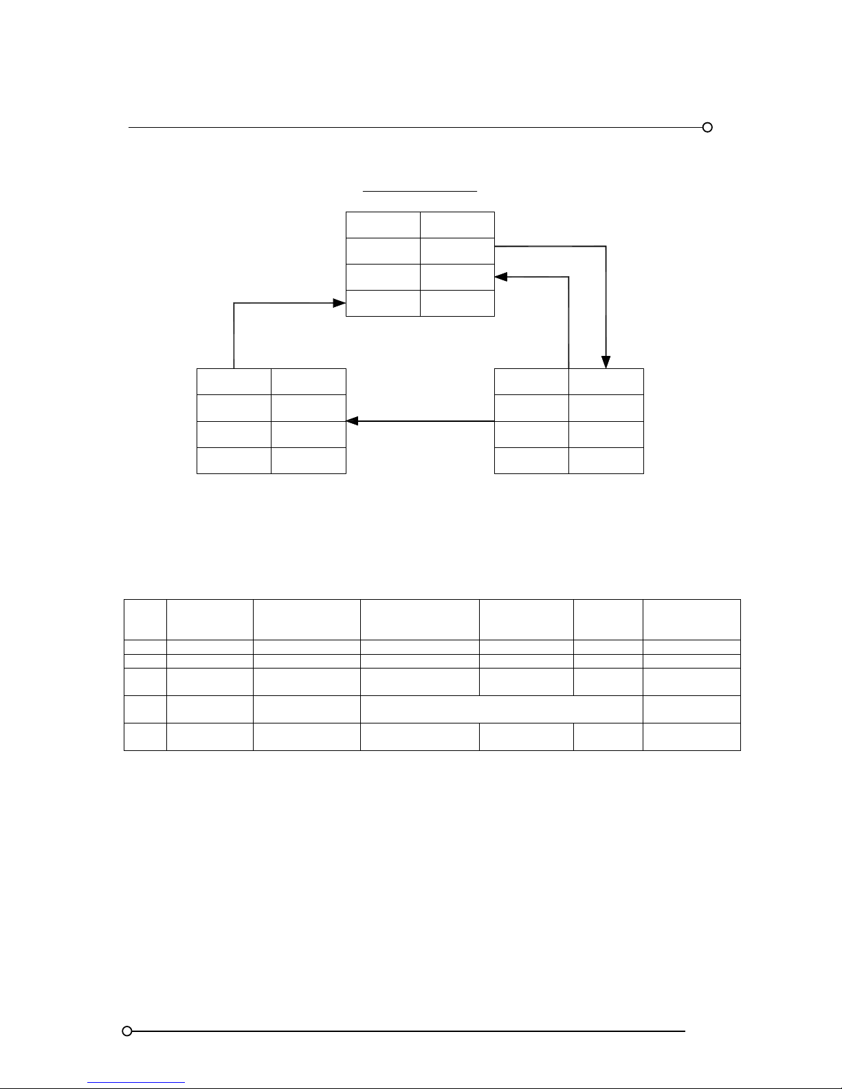
10.2 ISA-Sequence A - Automatic Reset
SEQUENCE TABLE
LINE
PROCESS
CONDITION
PUSHBUTTON
OPERATION
SEQUENCE
STATE
VISUAL
DISPLAY
ALARM
AUDIBLE
DEVICE
REMARKS
1 NORMAL NORMAL OFF SILENT
2 ABNORMAL ALARM FLASHING AUDIBLE LOCK-IN
3A ABNORMAL ACKNOWLEDGE ACKNOWLEDGED ON SILENT
MAINTAINED
ALARM
3B NORMAL ACKNOWLEDGE TO LINE 4
MOMENTARY
ALARM
4 NORMAL NORMAL OFF SILENT
AUTOMATIC
RESET
SEQUENCE FEATURES
1. ACKNOWLEDGE AND TEST PUSHBUTTONS
2. ALARM AUDIBLE DEVICE
3. LOCK-IN OF MOMENTARY ALARMS UNTIL ACKNOWLEDGED
4. THE AUDIBLE DEVICE IS SILENCED AND FLASHING STOPS WHEN ACKNOWLEDGED
5. AUTOMATIC RESET OF ACKNOWLEDGED ALARM INDICATIONS WHEN PROCESS
CONDITIONS RETURN TO NORMAL
6. OPERATION TEST
OFFVISUAL
SEQUENCE ISA A
(LOCK IN)
ABNORMALPROCESS
VISUAL
AUDIBLE
ON
SILENT
ACKNOWLEDGED
RETURN
TO NORMAL
PROCESS
ACKNOWLEDGE
WHILE ABNORMAL
VISUAL
AUDIBLE
SILENTAUDIBLE
ABNORMAL
FLASHING
AUDIBLE
ALARM
ACKNOWLEDGE
WHILE NORMAL
TO
ABNORMAL
SEQUENCE DIAGRAM
NORMAL
NORMALPROCESS
OR NORMAL
SEQUENCE
SEQUENCESEQUENCE
Page 32
RTK Series 725 Annunciator
32
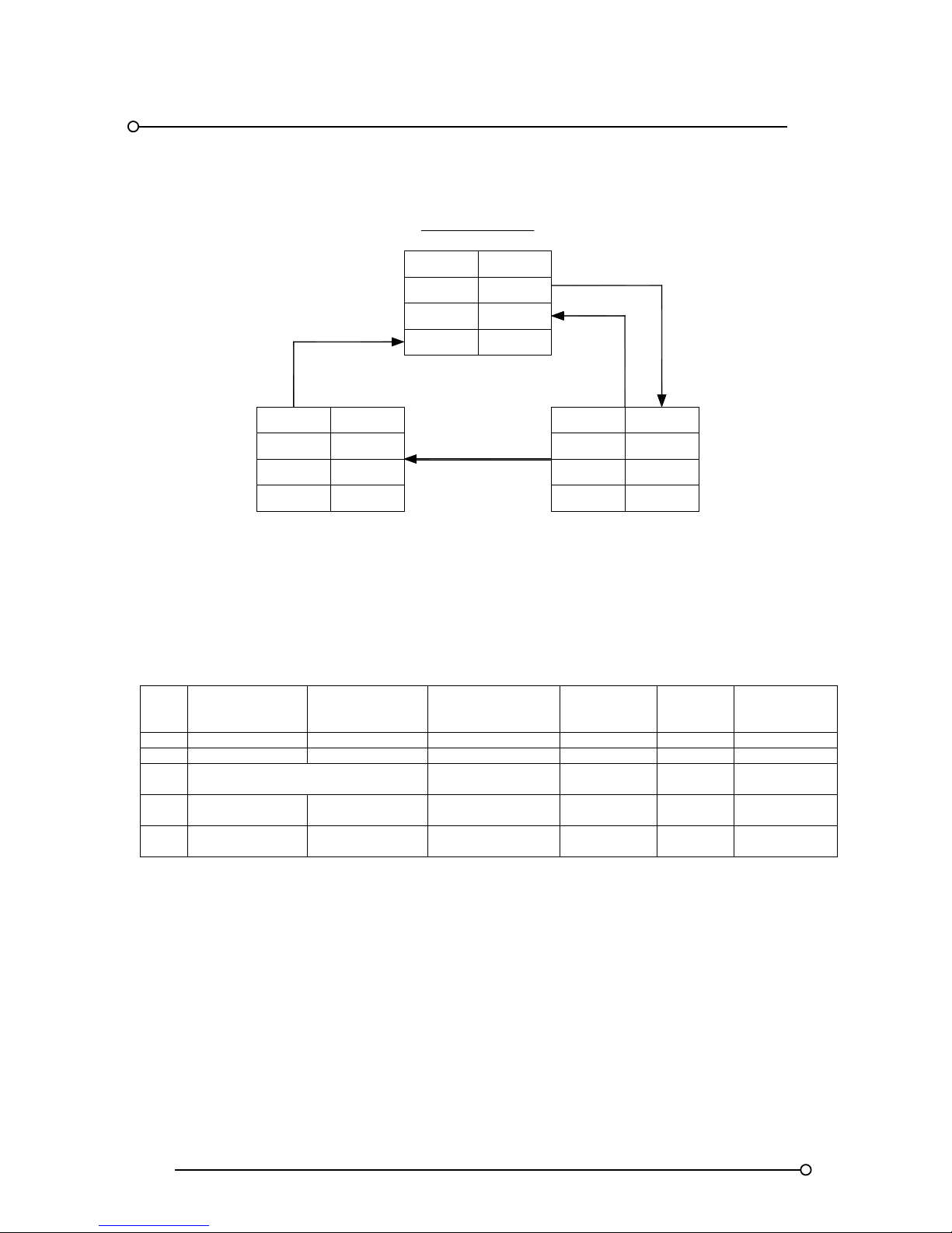
10.3 ISA-A-4 Sequence - Non Lock-In Function
SEQUENCE TABLE
LINE
PROCESS
CONDITION
PUSHBUTTON
OPERATION
SEQUENCE
STATE
VISUAL
DISPLAY
ALARM
AUDIBLE
DEVICE
REMARKS
1 NORMAL NORMAL OFF SILENT
2 ABNORMAL ALARM FLASHING AUDIBLE
3
RETURN TO NORMAL BEFORE
ACKNOWLEDGE
NORMAL OFF SILENT NON LOCK IN
4 ABNORMAL ACKNOWLEDGE ACKNOWLEDGED ON SILENT
MAINTAINED
ALARM
6 NORMAL NORMAL OFF SILENT
AUTOMATIC
RESET
SEQUENCE FEATURES
1. ACKNOWLEDGE AND TEST PUSHBUTTONS
2. ALARM AUDIBLE DEVICE
3. NON LOCK-IN OF MOMENTARY ALARMS
4. THE AUDIBLE DEVICE IS SILENCED AND FLASHING STOPS WHEN ACKNOWLEDGED
5. AUTOMATIC RESET OF ALARM INDICATIONS WHEN PROCESS CONDITIONS RETURN TO
NORMAL BEFORE OR AFTER ACKNOWLEDGE (NON LOCK-IN)
6. OPERATION TEST
RETURN
TO NORMAL
SEQUENCE ISA A - 4
(NON LOCK IN)
AUDIBLE
VISUAL
SILENT
ON
ACKNOWLEDGED
PROCESS ABNORMAL
ACKNOWLEDGE
WHILE ABNORMAL
AUDIBLE
VISUAL
SILENTAUDIBLE
PROCESS
AUDIBLE
FLASHING
ALARM
TO
ABNORMAL
SEQUENCE DIAGRAM
NORMAL
OFF
NORMAL
VISUAL
PROCESS
RETURN
TO NORMAL
SEQUENCE
SEQUENCESEQUENCE
ABNORMAL
OR NORMAL
Page 33
RTK Series 725 Annunciator
33
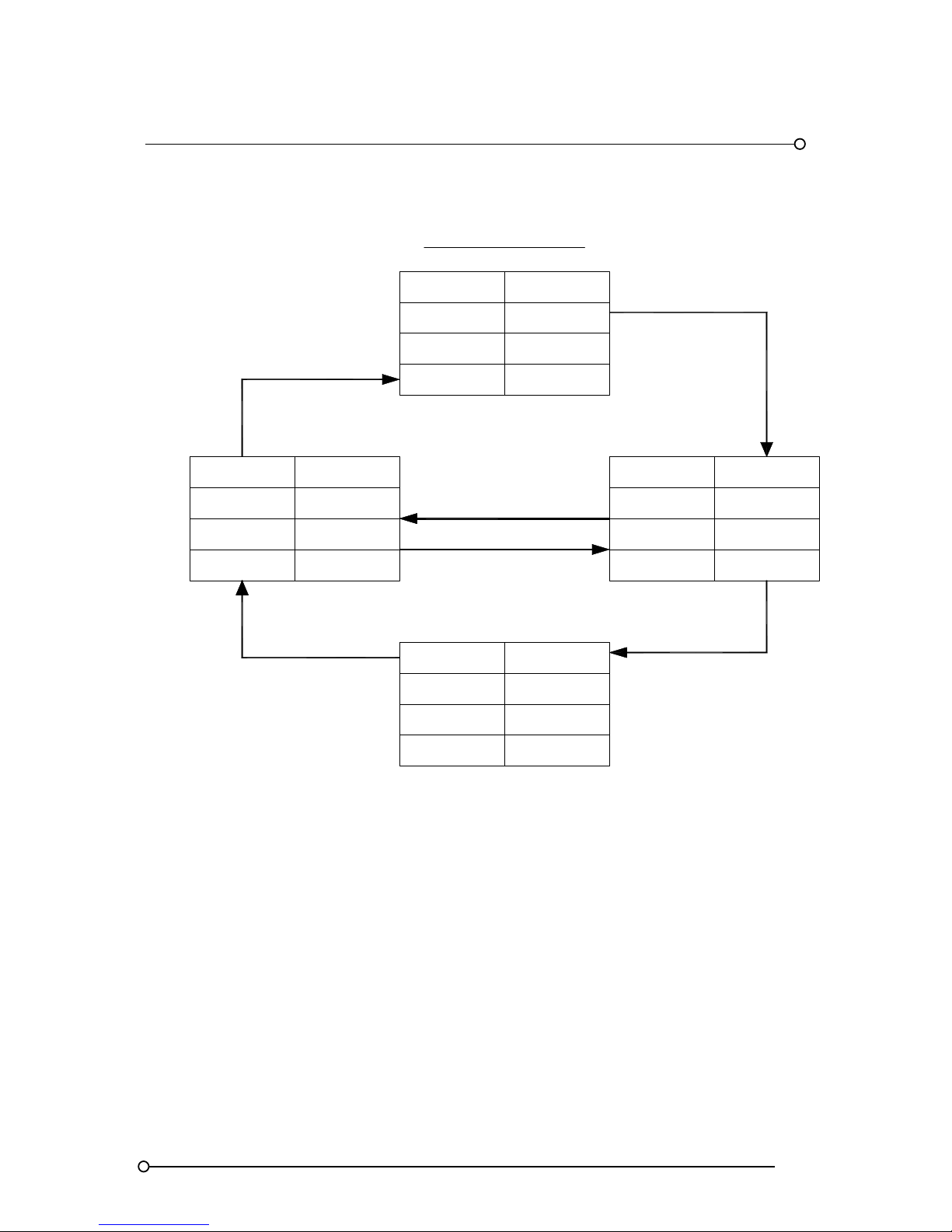
10.4 ISA-R Sequence - Ringback
AUDIBLE
RETURN
TO NORMAL
PULSING
SEQUENC E ISA R
(RING B A C K)
ACKNOWLEDGED
SILENT
ON
AUDIBLE
VISUAL
SEQUENCE
ABNORMALPROCESS
AUDIBLE AUDIBLE
PROCESS
VISUAL
SEQUENCE
SLOW FLASHING
RINGBACK
NORMAL
RESET
TO
ABNORMAL
ACKNOWLEDGE
WHILE NORMAL
VISUAL
SEQUENCE
PROCESS
OFF
NORMAL
SILENTAUDIBLE
VISUAL
SEQUENCE
FAST FLASH ING
ALARM
ABNORMAL
NORMAL
SEQUENCE DIAGRAM
PROCESS
OR NORMAL
ACKNOWLEDGE
WHILE ABNORMAL
RETURN
TO ABNORMAL
Page 34

RTK Series 725 Annunciator
34
SEQUENCE TABLE
LINE
PROCESS
CONDITION
PUSHBUTTON
OPERATION
SEQUENCE
STATE
VISUAL
DISPLAY
ALARM
AUDIBLE
DEVICE
REMARKS
1 NORMAL NORMAL OFF SILENT
2 ABNORMAL ALARM
FAST
FLASHING
AUDIBLE LOCK-IN
3A ABNORMAL ACKNOWLEDGE ACKNOWLEDGED ON SILENT
MAINTAINED
ALARM
3B NORMAL ACKNOWLEDGE TO LINE 4
MOMENTARY
ALARM
4 NORMAL RINGBACK
SLOW
FLASHING
SILENT
MANUAL
RESET
REQUIRED
5 ABNORMAL TO LINE 2
RETURN TO
NORMAL
6 NORMAL RESET NORMAL OFF SILENT
MANUAL
RESET
SEQUENCE FEATURES
1. ACKNOWLEDGE, RESET AND TEST PUSHBUTTONS
2. ALARM AUDIBLE DEVICE (OPTIONAL RINGBACK AUDIBLE DEVICE)
3. LOCK-IN OF MOMENTARY ALARMS UNTIL ACKNOWLEDGED
4. THE AUDIBLE DEVICE IS SILENCED AND FLASHING STOPS WHEN ACKNOWLEDGED
5. RINGBACK VISUAL AND AUDIBLE INDICATIONS WHEN PROCESS CONDITIONS RETURN
TO NORMAL.
6. MANUAL RESET OF RINGBACK INDICATIONS
7. OPERATION TEST
Optional Ringback Audible
As an option the Multifunction “MULT” Relay can be used to provide a separate Ringback audible if
required. When an alarm returns to normal a MULT relay set as a Ringback audible will activate until
the Reset Pushbutton has been pressed. (See Para 5.9 for details)
Page 35
RTK Series 725 Annunciator
35
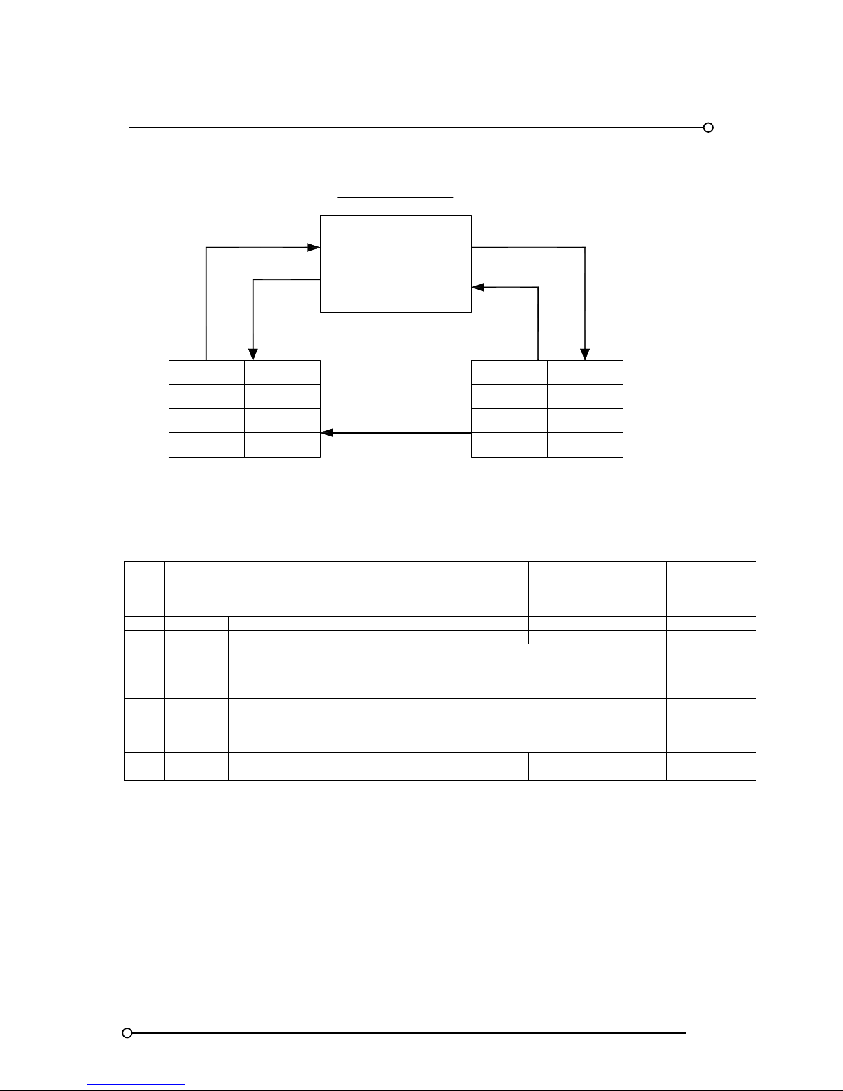
10.5 ISA-F1A Sequence - Automatic Reset First-Up
SEQUENCE TABLE
LINE
PROCESS
CONDITION
PUSHBUTTON
OPERATION
SEQUENCE
STATE
VISUAL
DISPLAY
ALARM
AUDIBLE
DEVICE
REMARKS
1 NORMAL NORMAL OFF SILENT
2 FIRST ABNORMAL FIRST ALARM FLASHING AUDIBLE LOCK-IN
3 SUB ABNORMAL ACKNOWLEDGED ON SILENT NO LOCK-IN
4A FIRST ABNORMAL ACKNOWLEDGE TO LINE 3
MAINTAINED
ALARM
FIRST OUT
RESET
4B FIRST NORMAL ACKNOWLEDGE TO LINE 3
MOMENTARY
ALARM
FIRST OUT
RESET
5 NORMAL NORMAL OFF SILENT
AUTOMATIC
RESET
SEQUENCE FEATURES
1. ACKNOWLEDGE, AND TEST PUSHBUTTONS
2. ALARM AUDIBLE DEVICE
3. LOCK-IN OF MOMENTARY FIRST ALARM ONLY. NO LOCK IN OF MOMENTARY
SUBSEQUENT ALARMS.
4. FLASHING AND AUDIBLE INDICATIONS FOR FIRST ALARM ONLY. NEW SUBSEQEUNT
ALARMS GO TO THE ACKNOWLEDGE STATE.
5. FIRST OUT INDICATION IS RESET AND THE AUDIBLE IS SILENCED WHEN
ACKNOWLEDGED.
6. AUTOMATIC RESET OF ACKNOWLEDGED ALARM INDICATIONS WHEN PROCESS
CONDITIONS RETURN TO NORMAL
7. OPERATIONAL TEST
NORMAL
NORMAL
SILENT
OFF
SEQUENCE DIAGRAM
SEQUENC E ISA F1A
(AUTOMATIC R E SE T F IRS T OU T WITH NO S UB S EQ U E N T A LA R M STA T E)
PROCESS
AUDIBLE
VISUAL
SILENT
ON
ACKNOWLEDGED
ABNORMAL
AUDIBLE
RETURN
TO NORMAL
SUBSEQUENT
TO ABNORMAL
VISUAL
PROCESS
AUDIBLE
VISUAL
AUDIBLE
FIRST ALARM
FLASHING
PROCESS
ABNORMAL
ACKNOWLEDGE
WHILE NORMAL
(FIRST OUT RE SE T)
FIRST TO
ABNORMAL
OR NORMAL
SEQUENCE
SEQUENCESEQUENCE
ACKNOWLEDGE
WHILE ABNORMAL
(FIRST OUT RESET)
Page 36
RTK Series 725 Annunciator
36
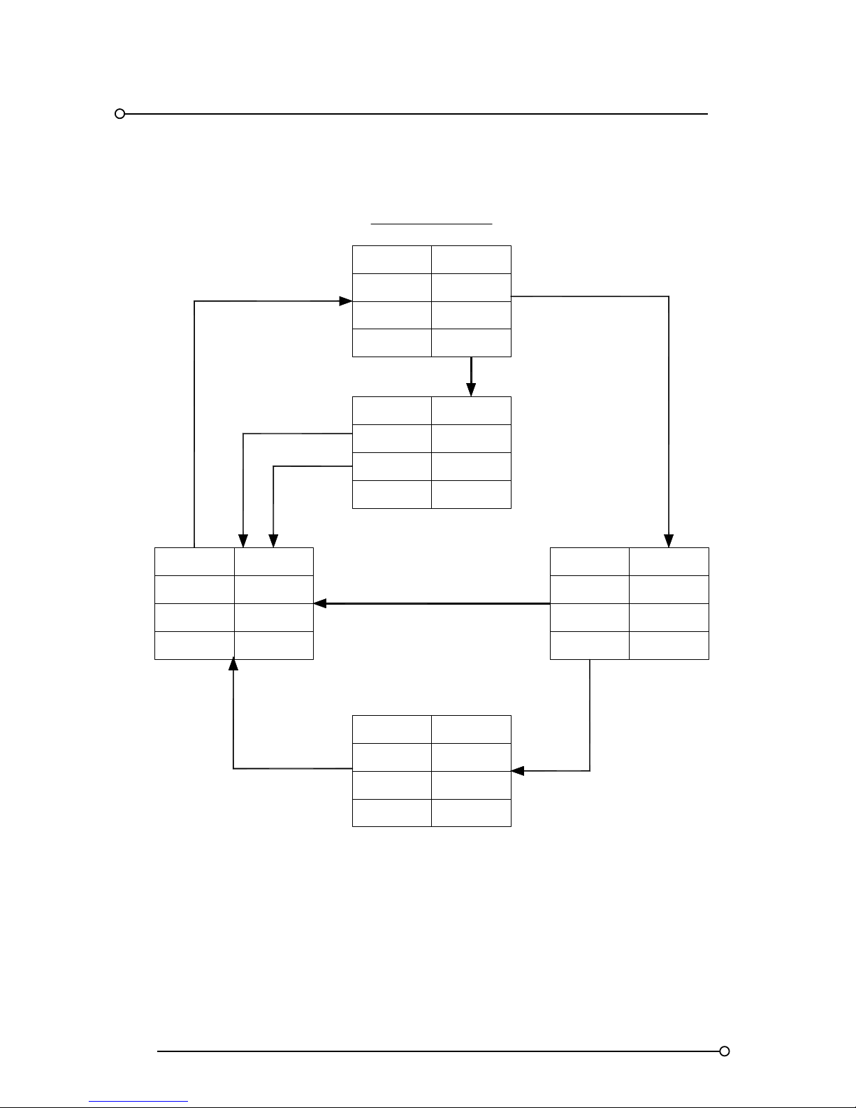
10.6 ISA-F2M-1 Sequence - Manual Reset First-Up
PROCESS
AUDIBLE
VISUAL
ACKNOWLEDGE
VISUAL ON
FIRST ALARM
SEQUENCE ISA F2M-1
(MANUAL RESET FIRST OUT WITH NO SUBSEQUENT ALARM FLASHING & SILENCED PUSHBUTTON)
AUDIBLE
ACKNOWLEDGE
(FIRST OUT RESET)
VISUAL
PROCESS
SILENT
FLASHING
FIRST SILENCED
SILENCE
ACKNOWLEDGE
(FIRST OUT RESET)
SILENT
ACKNOWLEDGED
ON
AUDIBLE
AUDIBLE
VISUAL
ON
PROCESS
AUDIBLE
FLASHING
ABNORMAL
SILENCE
PROCESS
RESET WHILE
NORMAL
AUDIBLE
VISUAL
PROCESS
SUBSEQUENT TO
ABNORMAL
SUBSEQUENT
ALARM
SILENT
OFF
NORMAL
NORMAL
FIRST TO
ABNORMAL
SEQUENCE DIAGRAM
OR NORMAL
ABNORMAL
OR NORMAL
ABNORMAL
OR NORMAL
ABNORMAL
OR NORMAL
SEQUENCE
SEQUENCE
SEQUENCE
SEQEUNCE
SEQUENCE
Page 37

RTK Series 725 Annunciator
37
SEQUENCE TABLE
LINE
PROCESS
CONDITION
PUSHBUTTON
OPERATION
SEQUENCE
STATE
VISUAL
DISPLAY
ALARM
AUDIBLE
DEVICE
REMARKS
1 NORMAL NORMAL OFF SILENT
2 FIRST ABNORMAL FIRST ALARM FLASHING AUDIBLE LOCK-IN
3 SUB. ABNORMAL SUB. ALARM ON AUDIBLE LOCK-IN
4 FIRST
ABNORMAL
OR NORMAL
ACKNOWLEDGE
BEFORE SIL
TO LINE 7
FIRST OUT
RESET
5 SUB.
ABNORMAL
OR NORMAL
6 FIRST
ABNORMAL
OR NORMAL
SILENCE FIRST SILENCED FLASHING SILENT
7 SUB.
ABNORMAL
OR NORMAL
SILENCE ACKNOWLEDGE ON SILENT
MANUAL
RESET
REQUIRED
8 FIRST
ABNORMAL
OR NORMAL
ACKNOWLEDGE
AFTER SILENCE
TO LINE 7
FIRST OUT
RESET
9 NORMAL RESET NORMAL OFF SILENT
MANUAL
RESET
SEQUENCE FEATURES
1. SILENCE, ACKNOWLEDGE, RESET AND TEST PUSHBUTTONS
2. ALARM AUDIBLE DEVICE
3. LOCK-IN OF MOMENTARY ALARMS UNTIL ACKNOWLEDGED.
4. OPTION1 – SILENCE PUSHBUTTON TO SILENCE THE ALARM AUDIBLE DEVICE
WHILE RETAINING THE FIRST OUT FLASHING INDICATION
5. FLASHING INDICATION FOR FIRST ALARM ONLY. NEW SUBSEQUENT ALARMS
HAVE THE SAME VISUAL INDICATION AS ACKNOWLEDGED ALARMS.
6. FIRST OUT INDICATION IS RESET WHEN ACKNOWLEDGED
7. MANUAL RESET OF ACKNOWLEDGED ALARM INDICATIONS AFTER PROCESS
CONDITIONS RETURN TO NORMAL.
8. OPERATIONAL TEST
Page 38
RTK Series 725 Annunciator
38
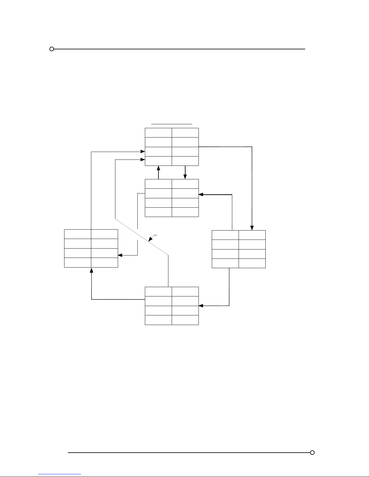
10.7 ISA-F3A Sequence - Automatic Reset First-Up
AUDIBLE
PROCESS
VISUAL
SEQUENCE
SEQUENCE ISA F3A
(AUTOMATIC RESET FIRST OUT WITHOUT FLASHING & RESET PUSHBUTTON)
FIRST OUT RESET
WHILE ABNORMAL
AUDIBLE
VISUAL
SEQUENCE
SILENT
PROCESS
ACKNOWLEDGE
SILENT
FIRST
SLOW FLASHING
ABNORMAL
AUDIBLE AUDIBLE
INTERMITTENT
FLASHING
FIRST ALARM
FIRST OUT RESET
SUBSEQUENT
ACKNOWLEDGE
ON
ABNORMAL
VISUAL
AUDIBLE
PROCESS
STATE
SEQUENCE
VISUAL
PROCESS
ON
SUBSEQUENT
ALARM
ABNORMAL
SEQUENCE DIAGRAM
RETURN
TO NORMAL
ACKNOWLEDGE
WHILE NORMAL
AUDIBLE
VISUAL
PROCESS
SEQUENCE
FIRST TO
ABNORMAL
SUBSEQUENT TO
ABNORMAL
SILENT
OFF
NORMAL
NORMAL
ABNORMAL
ACKOWLEDGED
OR NORMAL
ACKNOWLEDGE
WHILE ABNORMAL
OR NORMAL
OR NORMAL
FAST FLASHING
FIRST OUT RESET
WHILE NORMAL
Page 39

RTK Series 725 Annunciator
39
SEQUENCE TABLE
LINE
PROCESS
CONDITION
PUSHBUTTON
OPERATION
SEQUENCE
STATE
VISUAL
DISPLAY
ALARM
AUDIBLE
DEVICE
REMARKS
1 NORMAL NORMAL OFF SILENT
2 FIRST ABNORMAL FIRST ALARM
INTERMITTENT
FLASHING
AUDIBLE LOCK-IN
3 SUB. ABNORMAL SUB. ALARM
FAST
FLASHING
AUDIBLE LOCK-IN
4 FIRST
ABNORMAL
OR NORMAL
FIRST OUT
RESET BEFORE
ACKNOWLEDGE
TO LINE 3
FIRST OUT
RESET
5 FIRST
ABNORMAL
OR NORMAL
ACKNOWLEDGE
FIRST
ACKNOWLEDGED
SLOW
FLASHING
SILENT
FIRST OUT
RESET
REQUIRED
6A SUB. ABNORMAL
SUB.
ACKNOWLEDGE
ON SILENT
MAINTAINED
ALARM
6B SUB. NORMAL TO LINE 8
MOMENTARY
ALARM
7A FIRST ABNORMAL
FIRST OUT
RESET AFTER
ACKNOWLEDGE
TO LINE 6A
FIRST OUT
RESET
7B FIRST NORMAL TO LINE 8
FIRST OUT
RESET
8 NORMAL NORMAL OFF SILENT
AUTOMATIC
RESET
SEQUENCE FEATURES
1. SILENCE, ACKNOWLEDGE, RESET AND TEST PUSHBUTTONS
2. ALARM AUDIBLE DEVICE
3. LOCK-IN OF MOMENTARY ALARMS UNTIL ACKNOWLEDGED.
4. OPTION1 – SILENCE PUSHBUTTON TO SILENCE THE ALARM AUDIBLE DEVICE WHILE
RETAINING THE FIRST OUT FLASHING INDICATION
5. FLASHING INDICATION FOR FIRST ALARM ONLY. NEW SUBSEQUENT ALARMS HAVE THE
SAME VISUAL INDICATION AS ACKNOWLEDGED ALARMS.
6. FIRST OUT INDICATION IS RESET WHEN ACKNOWLEDGED
7. MANUAL RESET OF ACKNOWLEDGED ALARM INDICATIONS AFTER PROCESS
CONDITIONS RETURN TO NORMAL.
8. OPERATIONAL TEST
Page 40

RTK Series 725 Annunciator
40
11. Options
11.1 General
The standard 725 Series alarm annunciator is designed to meet the majority of alarm specifications
but in certain applications additional options may be required. Please note:- The following options
are usually specified at the time of ordering. Please consult factory if you would like to check
suitability of adding options to existing units.
11.2 LED Assemblies (Option LED)
Fit and forget LED assemblies, which plug into the same lamp socket as conventional filament
lamps, are available in the following colours Red, Amber, Yellow, White, Blue or Green. Please note
all alarm cards are equipped with dual function output drives allowing the standard card to be used
with either conventional filament lamps or LED’s. Switch SW1-8 on each card is used to select the
output drive characteristics.
FUNCTION SW1-8
Outputs suitable for driving lamps ON
Outputs suitable for driving LED’s OFF
11.3 Tropicalisation (Option TRO)
In harsh environmental conditions all of the associated cards are sprayed with a conformal coating
and sealed relays are used as required.
11.4 Individual Channel Repeat Relays (Option RLY)
As an option each dual channel alarm card within the annunciator can be supplied with two relays to
allow a repeat signal from each channel to be sent to third party devices as required. The non alarm
coil state of each relay can be set to be either:-
FEATURE FUNCTION SETTING
Normally energised F2 OFF
Normally de-energised F2 ON
The operation mode of each relay can be selected to be either:Input Follower
The individual relay will activate when an alarm occurs and automatically return to normal when the
signal input returns to the normal state.
FEATURE FUNCTION SETTING
Input follower
F18 OFF
F19 ON
Logic Follower
The individual relay will activate when an alarm occurs and only return to normal when the signal
input has returned to the normal state and the logic has reset, this may require the operator to press
the associated pushbuttons to reset the alarm depending on the sequence selected.
FEATURE FUNCTION SETTING
Logic follower
F18 ON
F19 OFF
Page 41
RTK Series 725 Annunciator
41
Display Follower
The individual relay will activate when an alarm occurs and faithfully mimic the state of the output
drive to the associated lamp (flashing, on or off)
FEATURE FUNCTION SETTING
Display follower
F18 ON
F19 ON
11.5 Individual Channel Dual Repeat Relays (Option RL2)
In applications that require two repeat relay outputs for each channel a dual channel alarm card
complete with repeat relays and a dual channel relay card are required. The dual channel relay card l
provides the additional set of volt-free changeover contacts. Please note:- As this feature requires
additional card slots it is only available on systems using medium or large windows.
11.6 Customer Specified Response Time (Option CRT**)
The response time for standard units is factory set at 25ms. If alternative response times are
required, option CRT is used to specify a fixed response time, between 1ms and 2 seconds.
11.7 Adjustable Response Time (Option AD*)
If specified at the time of order each channel can be supplied with a trim pot that allows the user to
adjust the response time between two set points as required.
AD1 = 5ms to 50ms, AD2 = 25ms to 2 seconds or AD3 = 5ms to 5 seconds
Please note: When setting activation delays it is important to note that the same delay will apply to
the return to normal state, for example:- If a channel is set for 5 Seconds delay the input contact
must be in the abnormal state for a minimum of 5 Seconds before the alarm activates. Once the input
contact has returned to normal the channel will not recognise the return to normal state for a
minimum of 5 Seconds and therefore the channel cannot be reset until this delay has elapsed.
On P725 annunciators supplied after March 2009 each channel is equipped with a switch, (SW2),
which allows the user to select
Return to normal state should have the same delay as the alarm activation or
Return to normal state as soon as the input returns to normal.
When using AD* options the user must use SW2 to set the normally open or normally closed input
state as detailed later in the manual. Function F1 should be set to OFF when using SW2 as
described in Section 24 of this manual.
11.8 Disable Integral Horn (Option DHN)
All units are supplied with an integral piezo audible as standard, which follows the critical audible
group (HNA). If remote audibles only connected to the integral horn relays are required the unit can
be supplied with the horn disabled.
11.9 Higher Field Contact Voltages (Option FCxx)
Standard 725 annunciators are able to accept powered signal inputs @ 24VAC/DC and as an option
the unit can be supplied suitable for direct connection to powered inputs
OPTION CODE VOLTAGE
FC048 48VAC / DC
FC125 125VAC / DC
FC250 250VAC / DC
Page 42

RTK Series 725 Annunciator
42
11.10 Supply Input/Output Module (Option SI/O)
The SI/O module is required in the following instances: -
1. In larger systems to distribute the 24VDC logic supply load evenly
2. To interlink multiple annunciator cabinets together to form larger systems
3. Where the pushbutton/programming module is fitted remote from the unit
This module is fitted within a standard cell but does not use a card slot so it does not affect the
number of alarm channels available.
11.11 RS485 Serial Communications (Option COM) Part No. CB4468POP1
All series 725 annunciators can be fitted with the optional ser ial communications card, which is
usually located in the cell directly above the pushbutton module. This card provides RS485 bidirectional communication to and from third party devices using modbus ASCII or modbus RTU
protocols as standard. All pushbutton controls can be local to the annunciator or driven remotely via
the communications link. Up to 64 annunciators can be multi-dropped on the same communications
connection.
11.12 Individual Channel Repeat Relays Powered By The Field Contact
Voltage (Option RAV)
Option RAV is used in safety critical applications to power the individual channel repeat relays using
the field contact supply voltage. In this mode even if the annunciator logic supply is lost the repeat
relay facility will continue to function as normal. Please note:- The repeat relay can only function as a
signal follower when option RAV is used.
11.13 Three Horn Relay Outputs (Option 3HN)
Option 3HN provides three horn relays, (HNA, HNB, GPB), and one common alarm relay (GPA)
instead of two horn and two group relays. Channels are programmed to operate any of the relays
using function codes, F23 = HNA, F24 = HNB, F22 = GPB, (F21 = GPA).
11.14 Three Group Relay Outputs (Option 3GP)
Option 3GP provides three group relays, (GPA, GPB, HNB), and one horn relay (HNA) instead of the
two horn and two group relays. Channels are programmed to operate any of the relays using function
codes, F21 = GPA, F22 = GPB & F24 = HNB, (F23 = HNA).
Please note:- The HNB relay is not equipped with a reflash function.
11.15 Repeat Pushbutton Output (Option RPB)
Option RPB provides two independent volt-free contact outputs, which follow the operation of a
chosen pushbutton. A two channel relay card is added to the system and switches on the card are
used to set the function of each relay to follow either:- System test, lamp test, silence, ack, reset or
first reset.
Page 43

RTK Series 725 Annunciator
43
11.16 Group Relays Follow Inputs (Option GFI)
Option GFI allows the GPA and GPB group relays to follow the function of the alarm contact. If an
alarm occurs within the group the relay will change state and will remain in the alarm condition until
the associated input has returned to normal. If multiple inputs within the group are in the alarm state
all inputs must return to normal before the group relay automatically returns to normal. Individual
channels can be assigned to the GPA and GPB relays, (function F21 & F22), in the normal way and
the optional reflash function, (Function F8 & F9), can be enabled as required.
11.17 Additional Group Relay Contact (Options 2GA or 2GB)
Option 2GA or 2GB is used in applications where a second isolated contact is required to work as a
slave of either the GPA or GPB relay, (Function F21 & F22), The multi function relay (MUL) located
in the SPR module is used to provide the additional contact.
11.18 Total Group Relay (Option RTG)
Option RTG is used in applications that require two common alarm groups, (GPA and GPB), PLUS a
total group relay. The multi function relay (MUL) located in the SPR module is used to provide the
total group relay contact, which automatically operates if either the GPA or GPB relay are activated.
11.19 SPR Module (Supply-Pushbuttons-Relay Module)
All Series 725 annunciators are equipped with 24VDC Logic. If external AC/DC or DC/DC Power
supplies are required they should be capable of handling the maximum surge current, which is
typically twice the maximum load when all lamps are on steady.
11.20 Logic Power Connections
In standard applications a power supply with a single 24VDC output can be wired to the 24VDC logic
power by connecting to terminals 0V and +V on the rear of the SPR Module.
11.21 Signal Supply Voltage Connections
In standard applications the logic supply terminals OV and +V can be cross-linked to the signal
supply input terminals OVC and +VC on the SPR module to provide +24VDC to distribute to the
associated field contacts. (OV links to OVC and +V links to +VC)
Page 44

RTK Series 725 Annunciator
44
11.22 Common Horn/Group/Multi-Function Relay & Remote P.B. Connections
Customer connections for the comm on functions should be wired to the rear of the SPR module.
These connections are shown below: -
COMMON CONNECTIONS
24VDC Logic power
(OV & +V)
24VDC Signal contact voltage
(OVC & +VC)
Dual horn relay contacts
Critical horn relay – HNA
Non critical horn relay - HNB
Dual common alarm relay contacts
Critical group relay – GPA
Non critical group relay - GPB
Multi
-
function relay contact
MUL
Optional remote pushbutton inputs
T = Lamp test
A = Acknowledge
R = Reset
ST = System test
M = Mute
FR = First reset
Pushbutton common connection = +V
Page 45
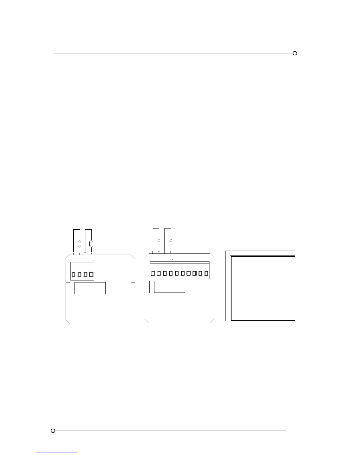
RTK Series 725 Annunciator
45
12. Large Window Alarm Module Wiring
Series 725 units supplied with large windows provide one alarm per cell. In order to maximise the
use of the standard two channel alarm card all odd cells within the annunciator, (1,3,5,7, etc), are
equipped with alarm cards and all even cells, (2,4,6,8, etc), are left unequipped. Channel 1 of the
alarm card is routed to the lamps or LED’s in the normal way and channel 2 is routed by the display
motherboard to the lamps or LED’s located in the cell directly below.
12.1 Standard Unit Without Repeat Relay Facility
Each cell is equipped with a type A2 back plate and a dual channel alarm card model no
CB5674POP1, which is suitable for 2 signal inputs. The alarm card is located in the upper card slot
12.2 Optional Unit With Repeat Relay Facility
Each cell is equipped with a type AR2 back plate and dual channel alarm card model no
CB5674POP2, which is suitable for 2 signal inputs a nd provides 2 relay outputs each having one set
of changeover contacts. The alarm card is located in the upper card slot
Wiring Details For A2 And AR2 Modules In Large Window Versions
WIRING FOR UNITS
WITH LARGE WINDOWS
WITH REPEAT RELAYS
CH*
INPUT
INPUT
WIRING FOR UNITS
WITH LARGE WINDOWS
WITHOUT REPEAT RELAYS
CH*
1
C
A2
C1
INPUT 1
INPUT 1
RELAY OUTPUTS
AR2
NCC2 NO R1
INPUT 2
DRIVES ALARM
IN CELL BELOW
R2NONC
2 C
1
INPUT 2
DRIVES ALARM
IN CELL BELOW
FRONT VIEW
WINDOW LA YOUT
Page 46
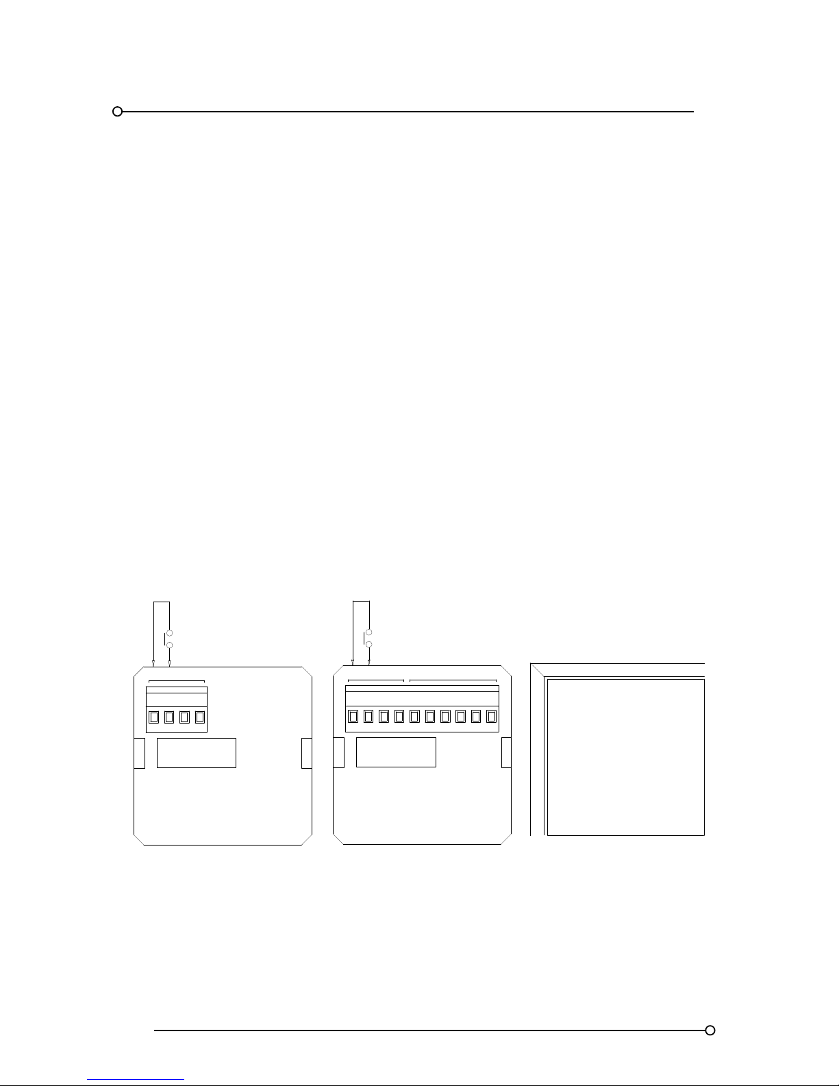
RTK Series 725 Annunciator
46
12.3 Large Window Versions Fitted With An Odd Number Of Alarms
Series 725 units that use large windows and have an odd no of total alarms in the system, 1,3,5,7,9,
ways etc, will be supplied with dual channel cards in alternative cells as described in the previous
paragraph with the exception of the last cell which will be supplied for use as a single alarm cell only
as detailed below.
12.4 Standard Unit Without Repeat Relay Facility
The last active alarm cell is equipped with a type A1 back plate and a dual channel alarm card model
no CB5674POP1, which is suitable for 2 signal inputs. The alarm card is located in the upper card
slot. Note. Only 1 channel is used in this configuration.
12.5 Optional Unit With Repeat Relay Facility
The last active alarm cell is equipped with a type AR1 back plate and dual channel alarm card model
no CB5674POP2, which is suitable for 2 signal inputs and provides 2 relay outputs each having one
set of changeover contacts. The alarm card is located in the upper card slot.
Note. Only 1 channel is used in this configuration.
Wiring Details For A1 And AR1 Modules Used In The Last Cell Of 725 Units
Fitted With Odd Numbers Of Alarms
WIRING FOR U NITS
WITH LARGE WINDOWS
WITH REPEAT RE LAYS
CH*
INPUT
INPUT
WIRING FOR UN ITS
WITH LARGE WINDOWS
WITHOUT REPE AT RELAYS
CH*
1 C
A1
C
1
INPUT 1
INPUT 1
RELAY OUTPUT
AR1
NC NO
R1
FRONT VIEW
WINDOW LAYOUT
LAST CHANNEL
Page 47
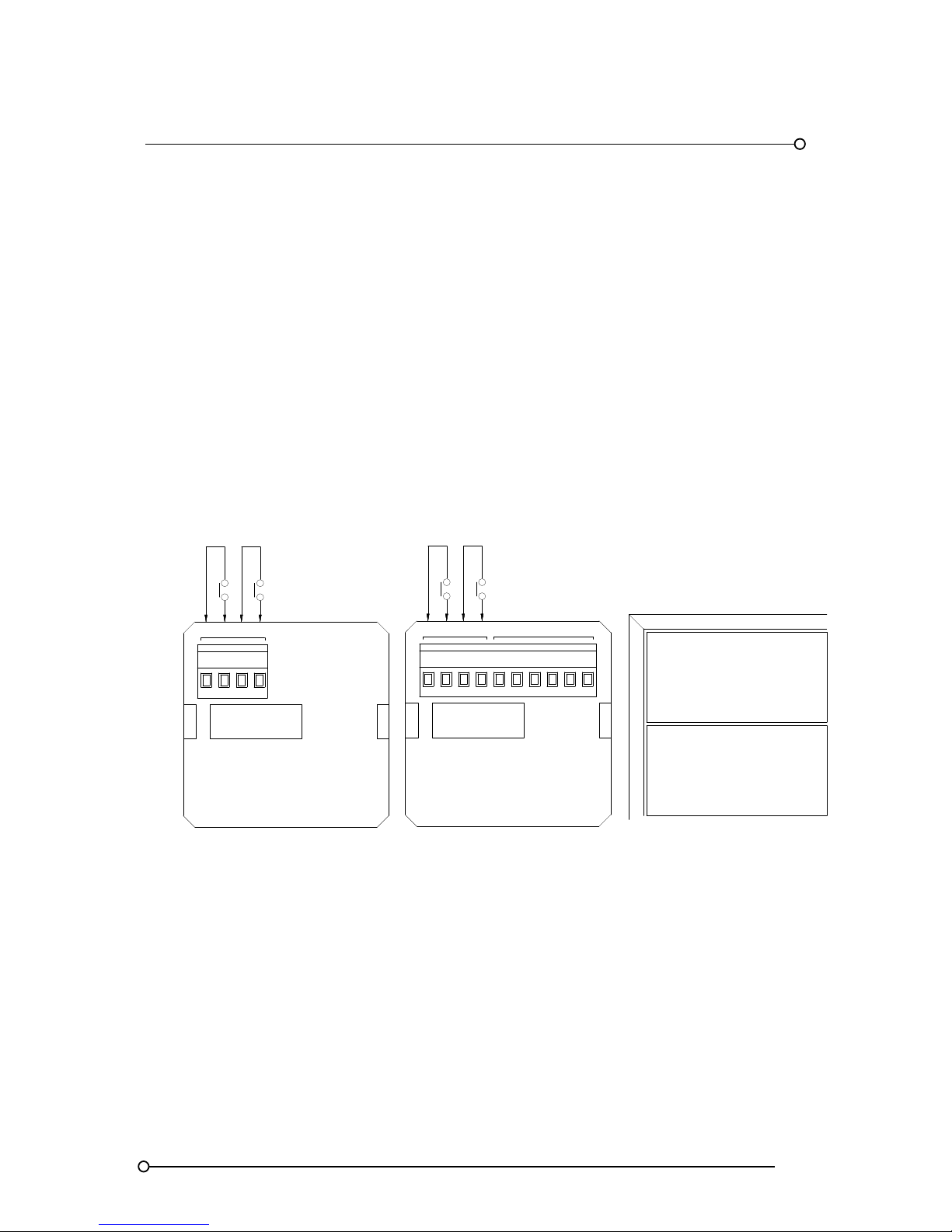
RTK Series 725 Annunciator
47
13. Medium Window Alarm Module Wiring
Series 725 units supplied with medium windows provide two alarms per cell.
13.1 Standard Version Without Repeat Relay Facility
Each cell is equipped with a type A2 back plate and a dual channel alarm card model no
CB5674POP1, which is suitable for 2 signal inputs. The alarm card is located in the upper card slot
13.2 Optional Version With Repeat Relay Facility
Each cell is equipped with a type AR2 back plate and dual channel alarm card model no
CB5674POP2, which is suitable for 2 signal inputs a nd provides 2 relay outputs each having one set
of changeover contacts. The alarm card is located in the upper card slot
Wiring Details For A2 And AR2 Medium Window Versions
A2
INPUT
RELAY
AR2
INPUT
WIRING FOR UNITS
WITH MEDIUM WINDOWS
WITHOUT REPEAT RELAYS
CH*
CH*
WIRING FOR UNITS
WITH MEDIUM WINDOWS
WITH REPEAT RELAYS
1
C2C R1NONC NC NO R2
1 C 2 C
LOWER
WINDOW
LOWER
WINDOW
UPPER
WINDOW
UPPER
WINDOW
1
2
FRONT VIEW
WINDOW LAYOUT
Page 48
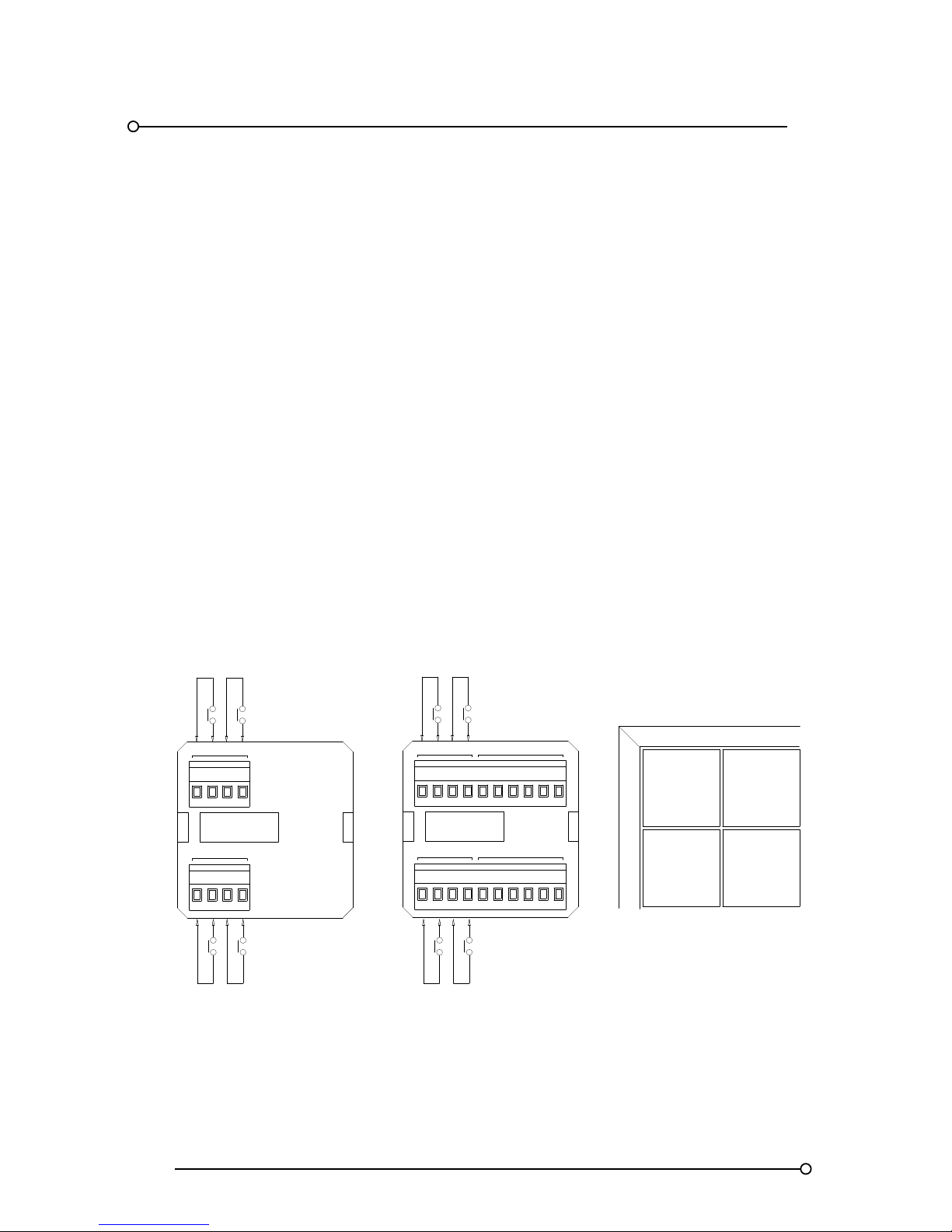
RTK Series 725 Annunciator
48
14. Small Window Alarm Module Wiring
Series 725 units supplied with small windows provide four alarms per cell.
14.1 Standard Version Without Repeat Relay Facility
Each cell is equipped with a type A4 back plate and two x dual channel alarm cards.
Model no CB5674POP1 suitable for 2 signal inputs. The alarm card is located in the upper card slot
and
Model no CB5647POP3 suitable for 2 signal inputs. The alarm card is located in the lower card slot
14.2 Optional Version With Repeat Relay Facility
Each cell is equipped with a type AR4 back pate and two x dual channel alarm cards
Model no CB5674POP2 suitable for 2 signal Inputs and equipped with 2 relay outputs each having
one set of changeover contacts is located in the upper card slot
Model no CB5674POP4 suitable for 2 signal Inputs and equipped with 2 relay outputs each having
one set of changeover contacts located in the lower card slot
Wiring Details For A4 And AR4 Small Window Versions
INPUT
INPUT
CH*
INPUT
INPUT 4INPUT 3
INPUT 3
CH*
34C C
INPUT
1
C2C
A4
3 C
1 C
INPUT 2INPUT 1
INPUT 1
RELAY OUTPUTS
INPUT 4
AR4
NC
RELAY OUTPUTS
R34NOC
NC
R4
NO
NCNC
2 C R1
NO NO
R2
INPUT 2
1 2
3 4
FRONT VIEW
WINDOW LAYOUT
Page 49
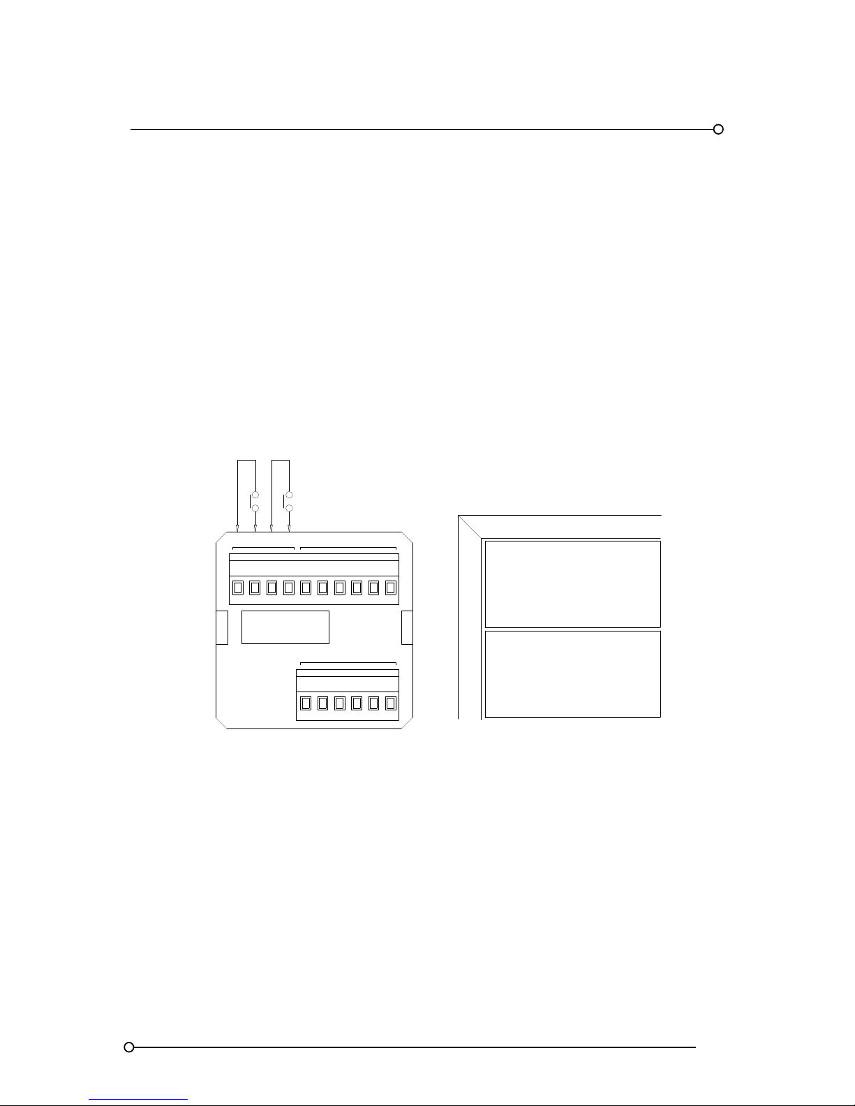
RTK Series 725 Annunciator
49
15. Dual Repeat Relay Option
15.1 Optional Version With Dual Repeat Relay Facility (Option RL2)
Each cell is equipped with a type AR* back plate, a dual channel alarm card and a dual channel
repeat relay card.
Relay contacts R1 and R1A operate in conjunction with channel 1
Relay contacts R2 and R2A operate in conjunction with channel 2
Please note relays R1A & R2A follow the functions set for relays R1 & R2 they cannot be set to
independently.
Wiring Details For Dual Repeat Relay Versions
INPUT
CH*
1
C
INPUT 1
RELAY OUTPUTS
NC
RELAY OUTPUTS
NONC NO
NCNC
2
C
R1
NO NO R2
INPUT 2
FRONT VIEW
WINDOW LAYOUT
R1A
R2A
1
2
AR*
Page 50
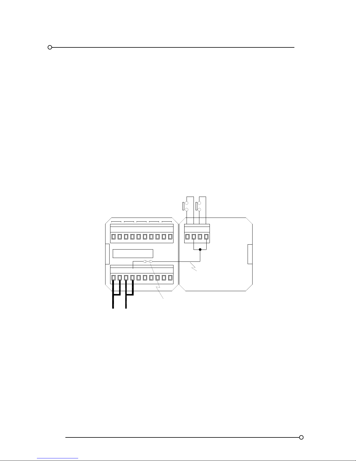
RTK Series 725 Annunciator
50
16. Signal Supply Voltage Options
16.1 Standard Systems With Combined Logic And Signal Supply.
In standard systems the 24VDC logic supply, OV and +V is cross-linked to the signal supply input
terminals, OVC and +VC to provide the voltage required to power the input contacts. Systems are
supplied with a factory fitted jumper between these terminals.
The signal supply input terminal +VC is used to internally link 24VDC Via a fuse to all of the common
terminals within the annunciator marked “C” ready for connection to customer signal contacts
Systems Using A Single 24VDC For Logic And Signal Supply
FR
MULT
SUPPLY 24VDC
+V
HNB
OV OVC
HNA
T
+VC
A STR M
SPR
GPA GPB
24VDC LOGIC
SUPPLY
1C2
C
INTERNAL DISTRIBUTION OF
SIGNAL SUPPLY VOLTAGE
INTERNAL
1A SIGNAL
SUPPLY FUSE
TYPICAL SIGNAL INPUTS
Earthing
All 725 Series Alarm Annunciators are fitted with a separate earth stud, which is located on the metal
frame extrusion.
Warning:- To ensure the final installation meets all relevant safety standards and EMC directives this
earth must be connected
Page 51
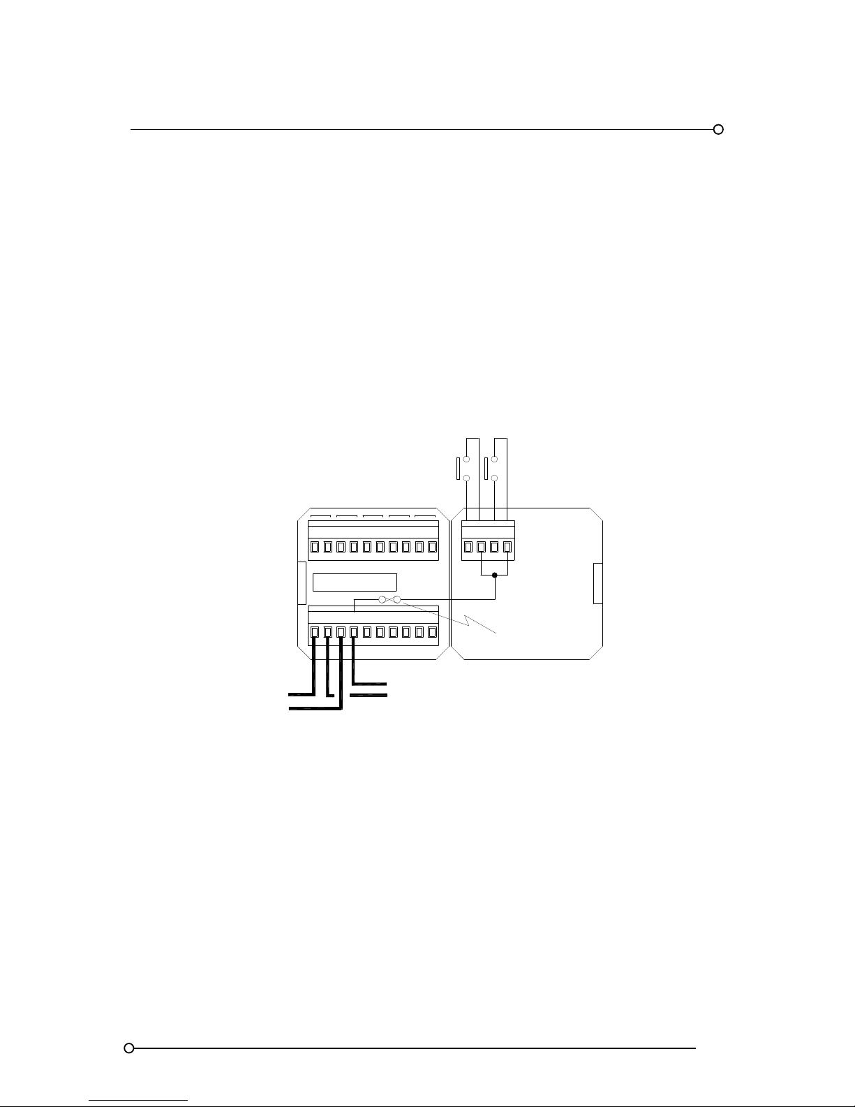
RTK Series 725 Annunciator
51
16.2 Standard Systems Using Externally Powered Inputs
24VDC powered inputs. As an option systems can use externally generated signal supply voltage
sources to power the inputs.
If the externally generated signal supply voltage is 24VAC/DC then the standard annunciator can be
used without modification.
The external supply should be connected to signal supply input terminals, OVC and +VC to distribute
the voltage required to power the input contacts. +VC is used to internally link the externally
generated signal supply voltage, via a fuse, to all of the common terminals within the annunciator
marked “C” to allow connection to customer signal contacts
Systems Using Isolated Logic And Signal Supplies
EXTERNALLY
GENERATED
SIGNAL
VOLTAGE
C2C1GPBGPAHNA HNB MULT
SPRSUPPLY 24VDC
+VCOVCOV +V
MRSTAT FR
24VDC LOGIC
SUPPLY
INTERNAL
1A SIGNAL
SUPPLY FUSE
TYPICAL SIGNAL INPUTS
16.3 Higher Voltage Direct Powered Inputs
If higher field contact voltages are required this must be specified at the time of the order to allow the
associated input conditioning components to be altered to suit. The following higher voltage
externally powered input options are available 48VAC/DC, 125VAC/DC, or 250VAC/DC. Wiring is
identical to the 24VDC-powered version shown above.
Page 52
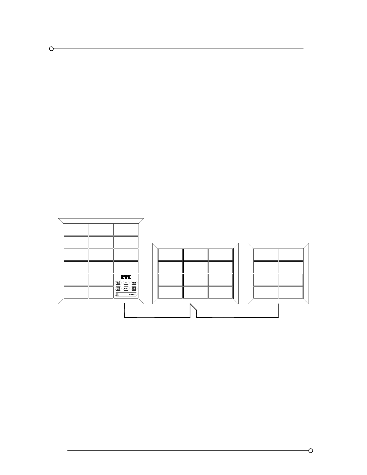
RTK Series 725 Annunciator
52
17. Common Pushbutton Module
17.1 P725 Systems Sharing A Common Pushbutton / Programme Module
Multiple Series 725 Annunciators can be supplied with one common pushbutton / programming
module to allow a number of cabinets to operate as a single system.
Each of the cabinets will be equipped with an additional card “option SI/O” which provides 24VDC
power connections and in / out ribbon sockets to allow all system connections, (First-Out Groups,
Horn Groups, Common Alarm Groups and Pushbutton Control), to be easily connected between
units.
A maximum of 256 alarm channels, distributed in cabinets to suit individual applications, can share a
single pushbutton / programming module
Multiple Annunciators Sharing A Common Programming / Pushbutton Module
UPTO A MAX OF 256
ALARM CHANNELS
Page 53
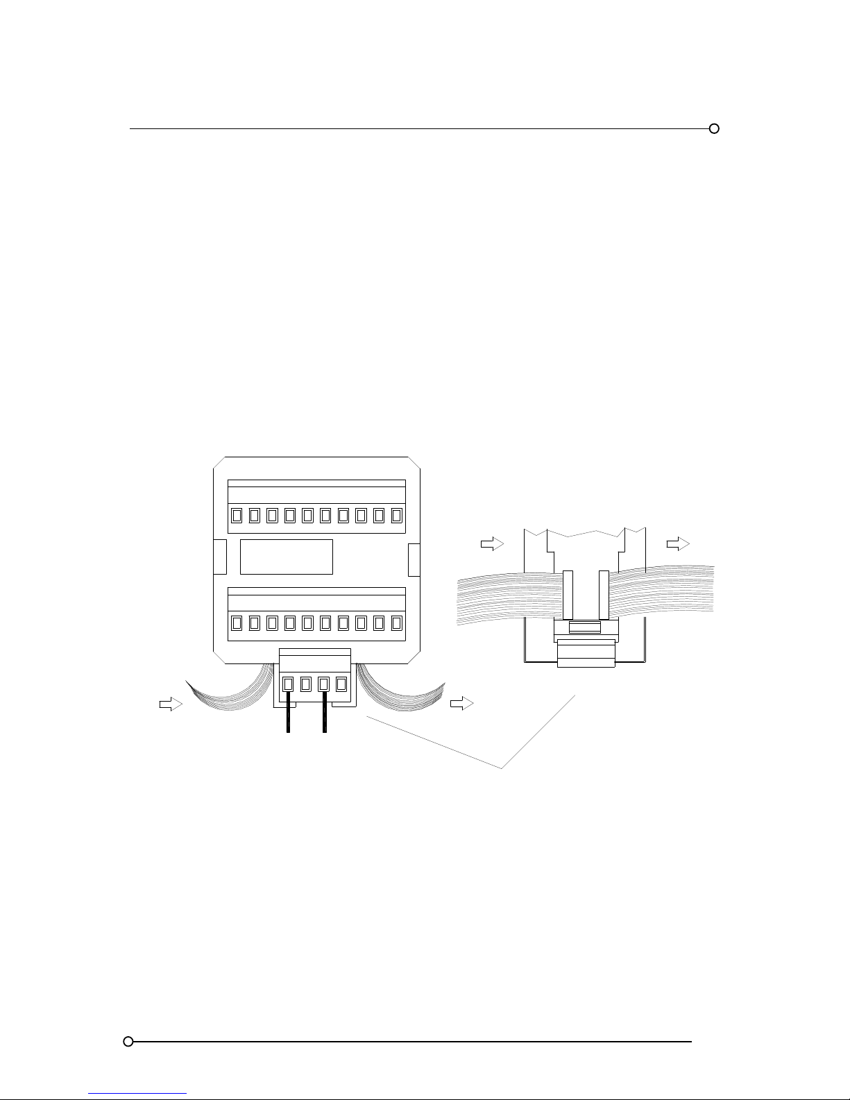
RTK Series 725 Annunciator
53
17.2 SI/O Module Details
Systems that require common pushbutton control between multiple cabinets or larger units that
require additional power distribution terminals are supplied with the optional SI/O card. The SI/O
module is located in the bottom row of each annunciator in the system to provide the additional
connections required for logic power distributions and ribbon in / ribbon out connections as shown
below. Once the ribbon cables and logic power have been connected the units will respond as a
single common system. Please note the SI/O card can be fitted in addition to any alarm cards
already located within the cell.
Warning:-
A 24VDC supply should be independently connected to each annunciator unit within the scheme.
Power should not be daisy chained between units, which would cause excessive current to flow
within single units.
SI/O Ribbon And Power Connections
OUT
FRONT OF UNIT
VIEW UNDER SI/O MODU LE
RIBBON FROM
ADJACENT UNIT
RIBBON TO
ADJACENT UNIT
24VDC LOGIC
SUPPLY
OV +V
CH*
FUSE
OV +V
RIBBON IN IN RIBBON OUT
OVC +VC
OVC +VC
Page 54
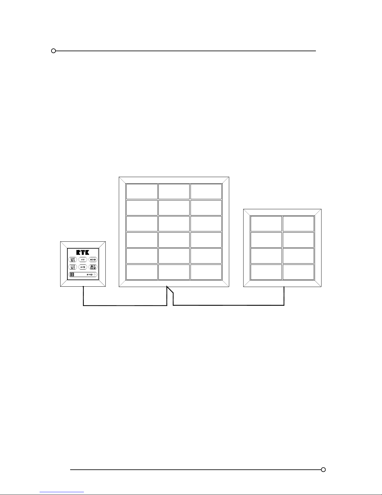
RTK Series 725 Annunciator
54
17.3 P725 Systems With Remote Pushbutton/Programming Module
As an option the pushbutton/programming module, which is required to control the alarm sequence
and to allow each channel to be programmed, can be located remote from the annunciator fascia.
One pushbutton module is capable of controlling a maximum of 256 alarm ways either in a single
cabinet or distributed between multiple annunciators. The remote pushbutton module is equipped
with terminals for the 24VDC logic supply, remote pushbuttons (if required) and the five common
relays. When using the programming module it is necessary to see the alarm channel windows you
are programming therefore the position of the module cannot be beyond a reasonable visual range.
Interconnections between units is via a 26 way ribbon cable which is available from RTK if required
Typical Applications Using Remote Pushbutton Module
UPTO A MAX OF 256
ALARM CHANNELS
17.4 Options For Mounting The Remote Version Of The Pushbutton Module
The remote Pushbutton/Programming module can be supplied suitable for:-
17.5 Panel Mounting Version
With this option the unit is mounted through a single panel cut-out and retained using the supplied
panel mounting clamps.
17.6 DIN-Rail Mounting Version
As an option the unit can be supplied with an optional DIN rail mounting to allow it to be mounted in
the back of the associated panel.
17.7 Wall Mounting Version
A wall mounting enclosure is also available which will house the pushbutton module plus
pushbuttons for test, acknowledge and reset and a 90dB audible alarm, if required.
Page 55
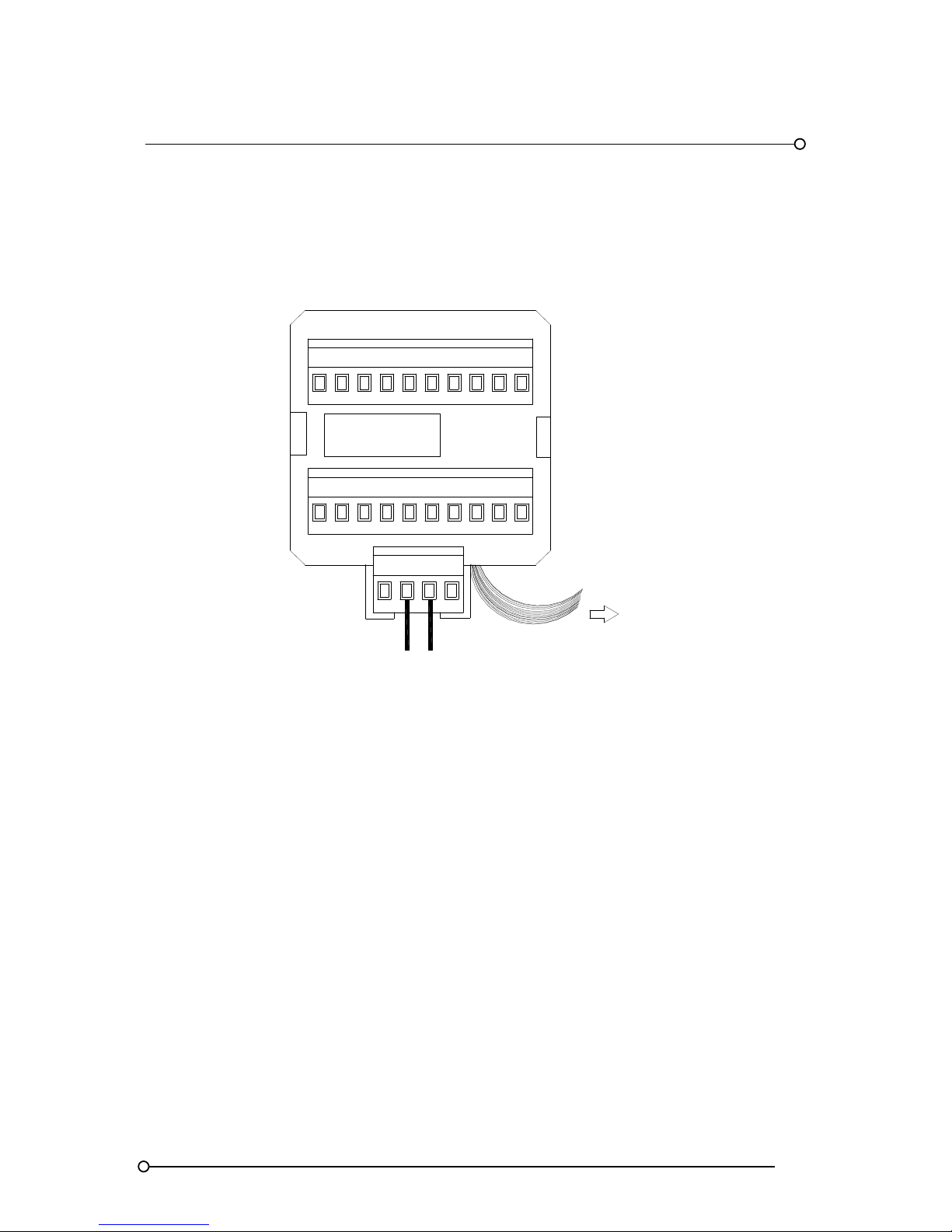
RTK Series 725 Annunciator
55
17.8 Remote Pushbutton Module Connections
In order for the remote pushbutton/programming module to operate correctly this unit should be
interconnected to the annunciator(s) using a ribbon cable as shown in the diagram below. This ribbon
cable can also connect to further annunciators if they are all to be configured and linked to the same
pushbutton module.
24VDC LOGIC
SUPPLY
+VOV OV +V
SUPPLY 24VDC
SPR
RIBBON TO
MAIN ANNUNCIATOR
SI/O MODULE
Warning
The 24VDC power supply must be independently wired to the programming module and the
annunciator. Never feed the power into one unit and daisy chain the wiring.
Page 56
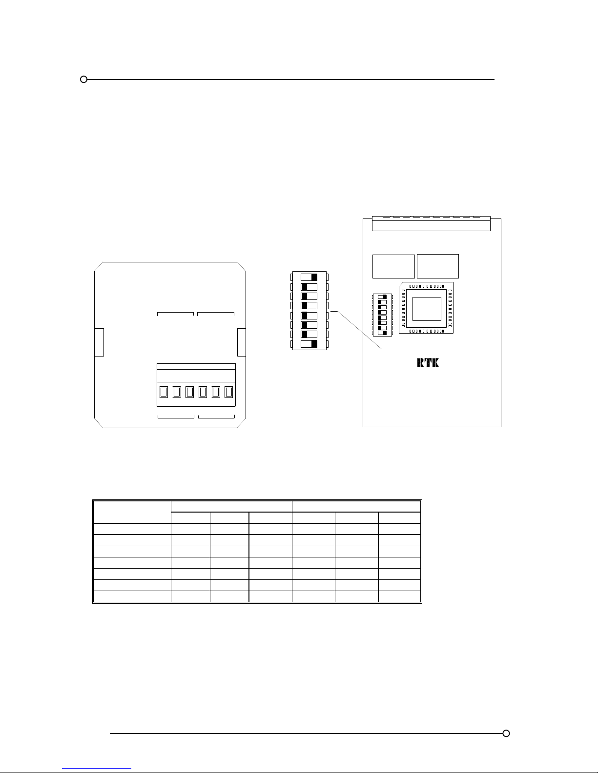
RTK Series 725 Annunciator
56
17.9 Repeat Pushbutton Outputs (Option RPB)
Option RPB provides two independent volt-free contact outputs, which follow the operation of a
chosen pushbutton. A two channel relay card is added to the system and switches on the card are
used to set the function of each relay to follow either:- System test, lamp test, silence, ack, reset, first
reset or sleep mode.
ON
RL2
SW1 DIL SWITCH
7
8
6
5
2
4
3
1
OFF
4
8
6
7
5
OFF
3
2
1
ON
ALARM CARD
RL1
A4506-*
R2NONCR1NONC
PB2PB1
SLAVE PUSHBUTTON
OUTPUT CONTACTS
RPB
CONTACT
OUTPUT
NO 2
CONTACT
OUTPUT
NO 1
Set Relay To Follow ** Pushbutton
PUSHBUTTON
CHANNEL NO.1 CHANNEL NO.2
SW1-1 SW1-2 SW1-3 SW1-4 SW1-5 SW1-6
Lamp Test ON OFF OFF ON OFF OFF
Acknowledge OFF ON OFF OFF ON OFF
Reset OFF OFF ON OFF OFF ON
Mute ON ON ON ON ON ON
System Test OFF ON ON OFF ON ON
First Reset ON OFF ON ON OFF ON
Sleep Mode ON ON OFF ON ON OFF
Pulse Duration
The contact can be set to remain closed for a defined period
SW1-7 OFF = 0.25 seconds or SW1-7 ON = 0.5 seconds
Page 57
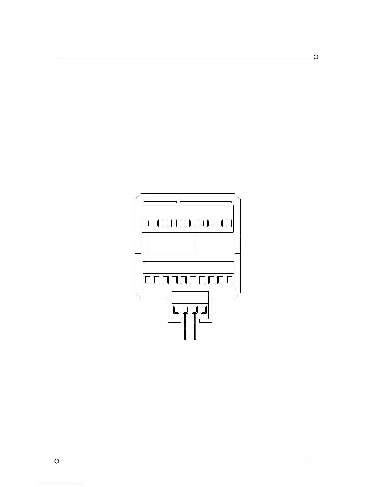
RTK Series 725 Annunciator
57
18. Power Distribution
Power Distribution On Large Annunciator Units
Systems greater than 32 cells are equipped with a minimum of one SI/O supply card to allow the
user to distribute the logic supply load and avoid excessive current being passed through the
motherboard. The first 32 cells in the annunciator are powered from the SPR module in the normal
way. Each SI/O card is designed to power a maximum of 16 cells in larger applications multiple SI/O
cards will therefore be present. With systems up to 48 cells the logic supply is factory wired between
the SPR and SI/O cells however on systems over 48 cells it is necessary to power the SPR and SI/O
cells using separate feed wires due to the higher currents required.
Typical SPR Module Wiring On AR4 Type Alarm Module
RELAY OUTPUTS
INPUT
CH*
NCC
4
C3
C
1
C2NC
NO
R4
NO R3 NC
NOR1NC R2NO
OVOV +V+V
24VDC LOGIC SUPPLY
SPR
Please Note:-
SI/O cards do not occupy the space of active alarm cards therefore units can be supplied fully
populated.
Page 58
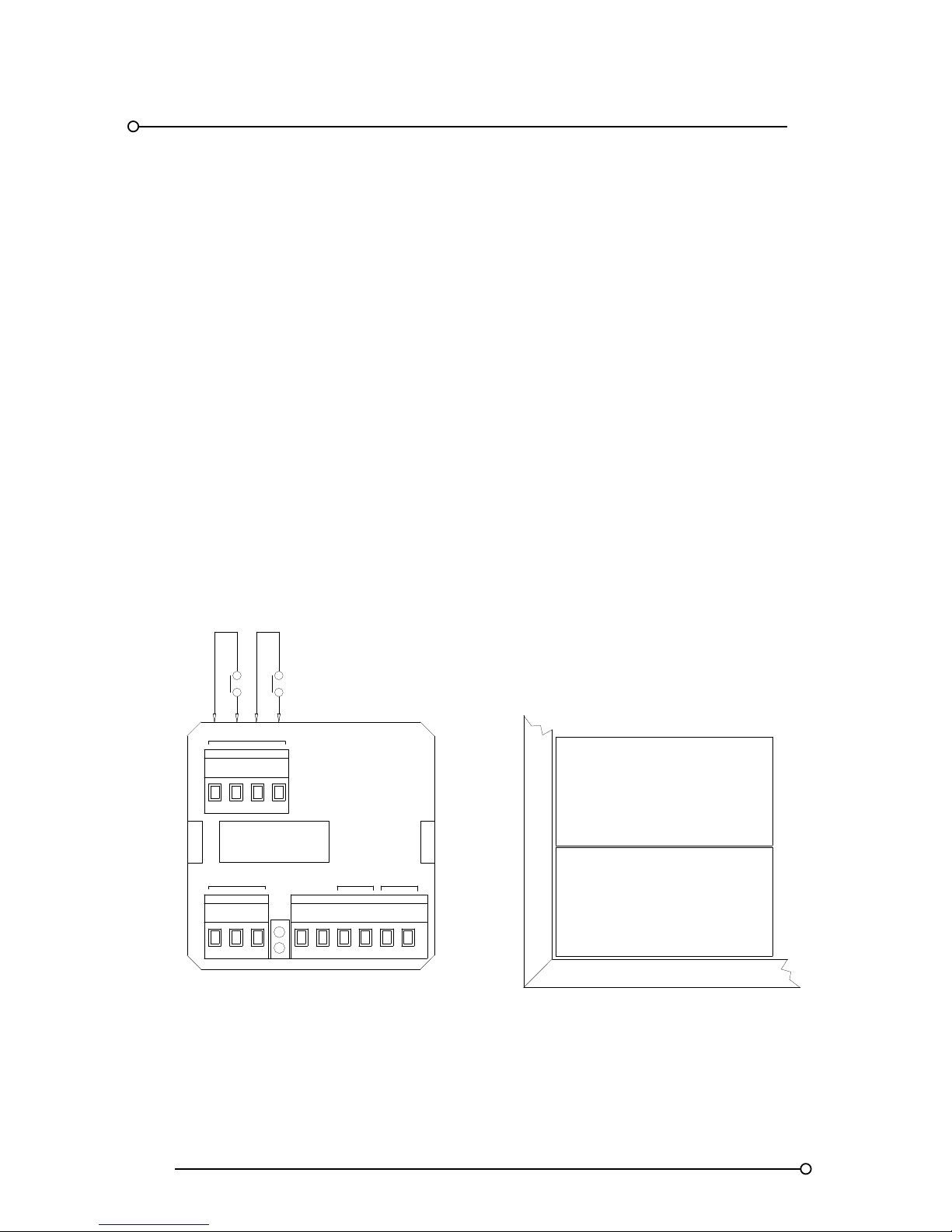
RTK Series 725 Annunciator
58
19. Systems Fitted With Serial Communications
Systems Fitted With The Serial Communications Option
All series 725 units can be supplied with a bi directional serial output card and RS485 serial port,
which can be used to transmit or receive serial alarm data to and from 3rd party devices on a
channel-by-channel basis or in master /slaves configurations between annunciators.
19.1 Connections
It is recommended that the RS485 communications output be wired in twin twisted pair cable, which
has both an inner and outer screen. The inner screen should be connected to the communications
0V line and one end of the outer screen should be taken to an instrument earth. It is also
recommended that the communication cable is run in separate trunking to cables carrying high
current or high voltages. The unit is provided with a communication watchdog relay, which is
normally energised and will de-energise if a communications fault occurs. Note:- (Rx) and (Tx) refers
to data transmission to the P725 annunciator i.e. Rx refers to data received in the annunciator and
TX refers to data transmission out of the annunciator.
Communications Card Fitted In Typical Medium Cell
INPUT
CA2CH*
R
COM RELAY
NONC
SCR B
A
RP
Tx
Rx
2C1 C
INPUT 1 INPUT 2
CHANNEL 2
CHANNEL 1
A
B
RX
TX
Note:- Full details of communication are provided later in the manual.
Page 59

RTK Series 725 Annunciator
59
20. System Configurations and Programming
Functions
The 725 Series Alarm Annunciator is always supplied with a comprehensive range of pre-defined
options which can be enabled or disabled on a channel by channel basis using the integral, (or as an
option remote), pushbutton / programming module. To simplify the configuration process each option
has been allocated a unique “Function No.” between 1 and 24, any combination of these functions
can be selected for each alarm way but care must be taken to ensure the operating modes selected
do not conflict with each other. For example if ringback alarm sequence R is required the system
should also be set to manual reset for the sequence to operate correctly. The key for functions 1 to
24 is shown later in the manual.
20.1 Programming Mode
The programme function of the unit is accessed by hinging down the pushbutton / programming
module using a small terminal screwdriver in the recess in the top of the bezel and levering forward
the top edge of the assembly. This allows the assembly to hinge down to reveal the programming
information plate. To programme the unit, first place it in the configuration mode by moving the yellow
switch to the “CONF” position, the "function" display will indicate 0 to confirm that the unit can be set.
Removal Of The Pushbutton/Programming Module
TERMINAL
SREWDRIVER
Page 60
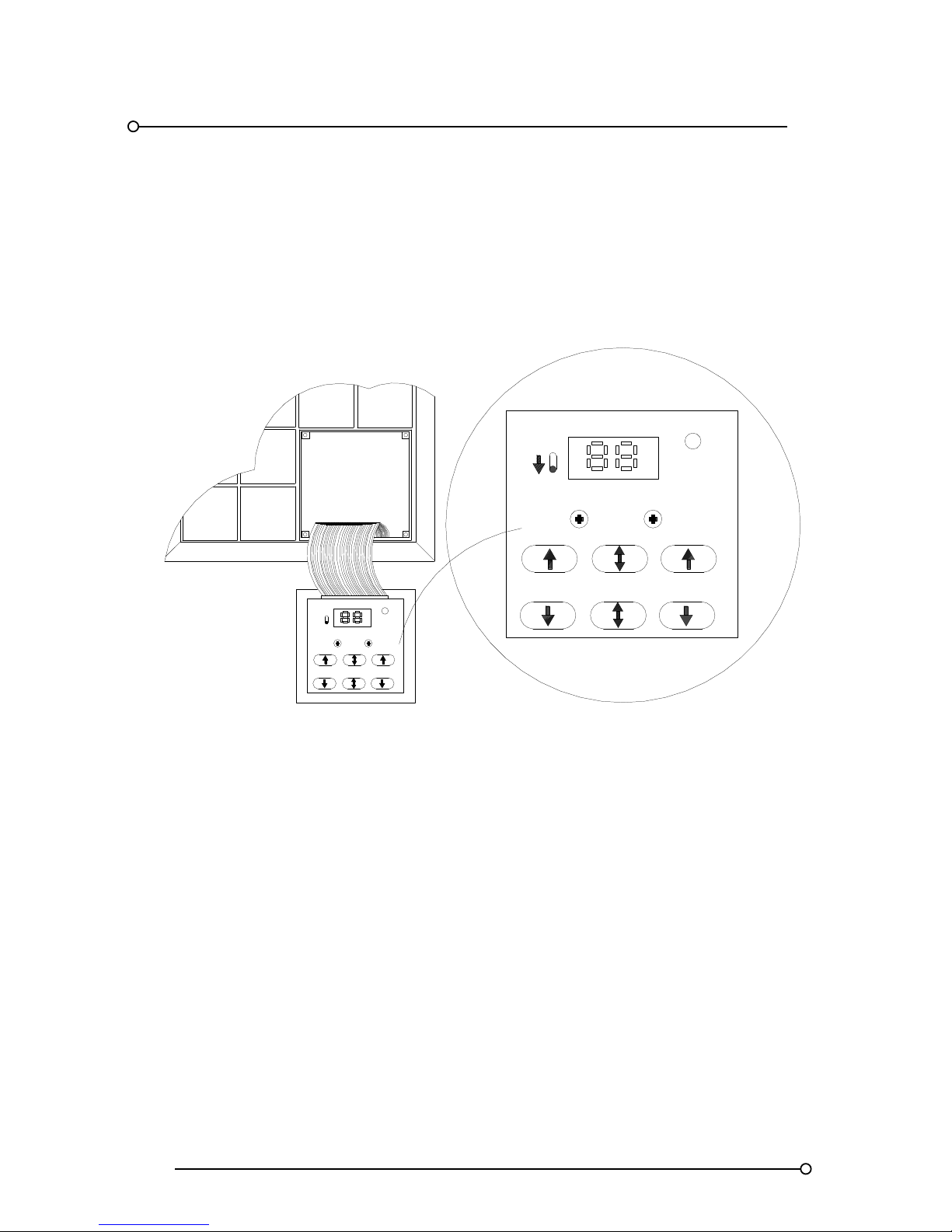
RTK Series 725 Annunciator
60
20.2 Changing A Function Setting
When the pushbutton / programming module has been hinged down and the “CONF”, “programme
mode”, switch has been placed to the ON position the operation of the pushbuttons changes as
indicated on the information plate on the underside of the unit as detailed below:-
Programming Information Plate Details
FUNCTION
STATUS
CHANNEL ST ATUS FUNCTION
STATUS
STATUSCHANNEL FUNCTION
FUNCTION
ON
OFF
CONF
CONF
Once the unit is in the (CONF), programme mode, the window associated with the channel selected
for programming will fast flash.
1. The lamp test / system test pushbuttons are used to select the required channel
2. The reset / first reset pushbuttons are used to select the required Function No.
3. The ack / mute pushbuttons are used to enable or disable the feature.
Note:- If the status LED is on the feature has been enabled.
Important note:-
If the user programmes a channel as detailed above and simply returns the unit to the run mode by
placing the CONF switch to the off position the information will not be stored. Programme changes
are only stored after the user has moved onto an adjacent channel, using the system test or lamp
test pushbuttons, at that point the programmed information is stored in EEPROM on the associated
alarm card
Page 61

RTK Series 725 Annunciator
61
20.3 Programming Example
Example:- If channel 7 is currently set to manual reset but the user would like to change this to allow
the window to automatically reset, (after acknowledge), the following procedure should be followed.
1. First hinge down the pushbutton module to access the programming plate.
2. Place the unit into (CONF), programming mode, using the yellow switch to the left of the
display
3. Use first reset / reset pushbuttons to select function 3 (reset function)
4. Use the system test / lamp test pushbuttons to select channel 7 and note the associated
window will fast flash.
5. Use the mute / ack pushbuttons to enable function F3 which is confirmed when the status
LED is on.
6. Scroll to the next channel up or down to store the required setting using the system test /
lamp test pushbuttons.
7. Return to normal operation by placing the CONF switch to the off state
20.4 Checking Programmed Settings
After all of the required functions have been set on the unit it is recommended that the user checks
the configuration to avoid problems during the commissioning stage. This is a simple process that
should only take a few minutes and is achieved by placing the unit into the “CONF” mode and
scrolling through each channel noting that as each Function is selected the status LED is on if
enabled or off if disabled. When functions such as F23 (Critical horn group HNA) are selected all
windows selected to operate the relay are illuminated in a steady on state to help the user identify
which alarms are within the horn group. Please note:- A window selected for programming
automatically fast flashes therefore the window of the channel that is being programmed cannot be
viewed to determine status information. The status LED on the information plate can be used as an
alternative to view the setting for this channel, if the status LED is on the function has been enabled,
or the user can move to an adjacent channel to allow the alarm window to be used in the normal
way.
20.5 Systems With Unarmed Ways
Each dual alarm card in the system is provided with a unique binary address, which is set using on
board DIL switches during manufacturing. If the system has been supplied with unarmed ways the
address normally used for the associated channels will be reserved to allow the user to add the card
at a later date. The programming module is designed to stop navigating between channels when it
detects a missing card address (normally the last card in the system). When the channel navigation
stops because of unarmed ways it is necessary to “jump over” the missing address to access any
further channels. To “jump” an address the user needs to hold down the reset pushbutton and then
press and hold the "channel up or down" pushbutton.
20.6 Points To Note When Programming
Alarm channels are always numbered in a standard format depending on window size and the
channel up / down pushbuttons are used to automatically move between each channel in the
correct order. The selected feature is only stored when the user selects an adjacent channel (either
going up or down). After the programming is complete it is recommended that the user checks the
required functions have been enabled correctly. After programming it is recommended that any
channels that have been changed are tested to ensure that the operation is in line with the required
functions. The programming process includes an inbuilt comprehensive error checking routine. In
applications where there is extreme electrical noise this may result in the program not being
accepted. If this happens, simply repeat the process for that particular alarm channel.
Page 62
RTK Series 725 Annunciator
62
21. Function No Key And Descriptions
If units are supplied with unarmed alarm channels it is necessary to jump over these missing cards
(addresses) to access the next channel.
General Description
The P725 is equipped with numerous pre-defined features that can be simply enabled or disabled on
a per channel basis as required. Functions numbers are assigned to each feature for ease of
selection.
Feature and Function Key
FEATURE FUNCTION
STATUS LED
OFF ON
Monitor current input contact state FO
Alarm Contact
Open
Alarm contact
closed
Set signal contact non alarm state F1
Normally
Open
Normally
closed
Set individual channel repeat
Relay non alarm state
F2
Normally
energised
Normally
de-energised
Set automatic or manual
Reset function
F3
Manual
Reset
Automatic
reset
Set fleeting alarm state F4 Lock in Non lock in
Set alarm to ringback sequence F5 N/A Ring bac k
Pushbutton interlock F6 Enable Disable
Input reflash F7 Disable Enable
Reflash critical group relay F8 Disable Enable
Reflash non critical group relay F9 Disab le Enable
Set alarm to first up sequence F0 F10* Disable Enable
Set alarm to first up sequence F1 F11 Disable Enable
Set alarm to first up sequence F2 F12 Disable Enable
Set alarm to first up sequence F3 F13 Disable Enable
Set alarm to be in first up group A F14* Disable Enable
Set alarm to be in first up group B F15 Disable Enable
Set alarm to be in first up group C F16 Disable Enable
Set alarm to be in first up group D F17 Disable Enable
Set repeat relays to follow logic
F18
Disable Enable
Set repeat relays to follow input
F19
Disable Enable
Set repeat relays to follow lamps
F18 & F19
Disable Enable
Repeat relays inhibited on test F20 Disable Enable
Set alarm to critical group relay F21* Disable Enable
Set alarm to non critical group relay F22* Disable Enable
Set alarm to critical horn relay F23* Disable Enable
Set alarm to non critical horn relay F24* Disable Enable
Note 1:- The Functions marked with the * are the default settings if no programming is requested with
the order
Note 2:- Functions F2, F18 & F19 are only available if individual channel repeat relays are fitted
(Option RLY).
Page 63
RTK Series 725 Annunciator
63
22. Function Descriptions
Function Numbers are used to describe pre-defined features that can be enabled or disabled by the
Customer as required.
F0- Contact Status
Function F0 allows each window in the annunciator to be illuminated if the associated signal contact
is in the closed state. This is normally used to help the user identify the current state of the input
device from the front of the unit without disturbing plant wiring.
F1- normally open (N/O) or normally closed (N/C) signal input contact
Each alarm input can be configured to allow operation from a N/O or N/C field contact.
FEATURE-F1 STATUS LED
Set channel to operate from a normally open signal input contact OFF
Set channel to operate from normally closed signal input contact ON
Please note: When using Option AD* (Customer Adjustable Response Time) on P725 Annunciators
shipped after March 2009 “F1” should be set to OFF and Switch SW2 located on each (2) channel
alarm card should be used to set the input state to normally open or normally closed as described in
Section 24 of this manual.
F2- Individual Channel Output Relay State
This feature is only available if individual channel repeat relays, option RLY, are fitted to the
annunciator.
FEATURE-F2 STATUS LED
Set individual channel repeat relay to be normally energised in non alarm
state
OFF
Set individual channel repeat relay to be normally de-energised in non
alarm state
ON
F3- Manual Or Automatic Reset
Acknowledged alarms can be set to manual reset where the operator must press the reset
pushbutton to clear the alarm after the input has returned to normal or acknowledged alarms can be
set to automatic reset which allows the alarm to automatically clear as soon as the input returns to
normal.
FEATURE-F3 STATUS LED
Set channel to manual reset OFF
Set channel to automatic reset ON
F4- Lock-In Or Non-Lock-In Operation
Alarms that occur and return to normal can be set to lock-in where the alarm is maintained until
acknowledge and reset has been pressed. (Depending upon sequence selected) or alarms that
occur and return to normal can be set to non-lock-in which allows the alarm to automatically return to
the off state as soon as the input returns to normal.
FEATURE-F4 STATUS LED
Set channel to lock-in OFF
Set channel to non-lock-in ON
Page 64
RTK Series 725 Annunciator
64
F5- Ringback Sequence
Ringback sequence is used to inform the operator that an acknowledged alarm has returned to
normal. When an acknowledged alarm returns to normal the associated window will slow flash to
indicate to the operator that the alarm can be reset.
FEATURE-F5 STATUS LED
Set channel to ringback not required OFF
Set channel to ringback sequence ON
Please note:- Function F3, F4 must be set to the off state for ringback sequence to function correctly.
As an option a unique sounding ringback audible can be wired to the unit, which will provide audible
notification that the alarm can be reset. The ringback audible feature is described later in the manual
F6- Reset Pushbutton Optional Function
If required the reset pushbutton can be used for both acknowledge and reset.
FEATURE-F6 STATUS LED
Set channel to allow acknowledge & reset pushbuttons to operate
independently
OFF
Set channel to allow the reset pushbutton to be used for acknowledge &
reset
ON
F7- Input Reflash (Re-Alarm)
On Manual Reset Sequences Input reflash is used to inform the operator that an acknowledged
alarm waiting to be Reset has returned to normal and re-alarmed.
FEATURE-F7 STATUS LED
Set Channel To Disable Input Reflash OFF
Set Channel To Enable Input Reflash ON
F8- Critical Group Relay Reflash Function
Group relays are typically used to inform third party devices that there is an alarm within a local
panel, however in the standard mode additional alarms occurring within the same group will not
change the state of the relay if one alarm remains active. The reflash function allows the relay to
change state for 0.5 seconds every time a new alarm occurs within the same group.
FEATURE-F8 STATUS LED
Set channel to disable reflash function on critical group relay OFF
Set channel to enable reflash function on critical group relay ON
Please note:- Only alarms with function F21 set to on will activate the critical group relay.
Page 65
RTK Series 725 Annunciator
65
F9- Non-Critical Group Relay Reflash Function
Group relays are typically used to inform third party devices that there is an alarm within a local
panel, however in the standard mode additional alarms occurring within the same group will not
change the state of the relay if one alarm remains active. The reflash function allows the relay to
change state for 0.5 seconds every time a new alarm occurs within the same group.
FEATURE-F9 STATUS LED
Set channel to disable reflash function on non-critical group relay OFF
Set channel to enable reflash function on non-critical group relay ON
Please note:- Only alarms with function F22 set to on will activate the non critical group relay.
F10- First-Up Sequence FO Or Enable Slow Flash On Non-First Out
Sequences
This feature is used to enable first-up sequence FO on individual channels as required. Full
sequence tables are provided in Section 10
FEATURE-F10 STATUS LED
Set channel to first-up sequence FO not required OFF
Set channel to first-up sequence FO required ON
Please note:- F10 is used to enable slow flash for non first up sequences.
F11- First-Up Sequence F1
This feature is used to enable first-up sequence F1 on individual channels as required. Full sequence
tables are provided in Section 10
FEATURE-F11 STATUS LED
Set channel to first-up sequence F1 not required OFF
Set channel to first-up sequence F1 required ON
F12- First-Up Sequence F2
This feature is used to enable First-Up sequence F2 on individual channels as required. Full
sequence tables are provided in Section 10
FEATURE-F12 STATUS LED
Set channel to first-up sequence F2 not required OFF
Set channel to first-up sequence F2 required ON
F13- First-Up Sequence F3 Or Enable Fast Flash On Non-First Out Sequences
This feature is used to enable first-up sequence F3 on individual channels as required. Full sequence
tables are provided in Section 10
FEATURE-F13 STATUS LED
Set channel to first-up sequence F3 not required OFF
Set channel to first-up sequence F3 required ON
Please note:- F13 is used to enable fast flash for non first out sequences
Page 66
RTK Series 725 Annunciator
66
F14 - First-Up Group A
All alarms set to function F14 will operate as a single first-up group in accordance with the selected
first-up sequence. F14 is the function code allocated for first-up Group A.
FEATURE-F14 STATUS LED
Set to remove channel from first-up Group A OFF
Set to include channel in first-up Group A ON
F15 - First-Up Group B
All alarms set to function F15 will operate as a single first-up group in accordance with the selected
first-up sequence. F15 is the function code allocated for first-up Group B.
FEATURE-F15
STATUS LED
Set to remove channel from first-up Group B OFF
Set to include channel in first-up Group B ON
F16 - First-Up Group C (Four First-up Group version only)
All alarms set to function F16 will operate as a single first-up group in accordance with the selected
first-up sequence. F16 is the function code allocated for first-up Group C.
FEATURE-F16 (FOUR FIRST-UP GROUP VERSION ONLY) STATUS LED
Set to remove channel from first-up Group C OFF
Set to include channel in first-up Group C ON
F16 – Alarm Input Selection (Standard version)
On standard units that have the communications capability enabled there are only two first-up groups
A and B. On these units Function 16 is used to configure how the communications operate.
With the communications option fitted it is possible to receive alarms in the normal way, from
volt-free contacts, or via the serial communications port. This function is used to select where the
system is looking to receive this alarm information. If the function is not selected then the normal
volt-free contacts are used. If the function is selected then the serial communications port will be
monitored for details of alarm status. It is possible to set this feature on an individual channel basis
hence having some alarm channels monitoring volt-free contacts and some monitoring the
communications.
FEATURE-F16 (STANDARD VERSION) STATUS LED
Set to get alarm information from volt-free contact input OFF
Set to get alarm information from the serial communications ON
F17 - First-up Group D (Four First-up Group version only)
All alarms set to function F17 will operate as a single first-up group in accordance with the selected
first-up sequence. F17 is the function code allocated for first-up Group D.
FEATURE-F17 (FOUR FIRST-UP GROUP VERSION ONLY) STATUS LED
Set to remove channel from first-up Group D OFF
Set to include channel in first-up Group D ON
Page 67
RTK Series 725 Annunciator
67
F17 – Alarm Logic Selection (Standard version)
On standard units that have the communications capability enabled there are only two first-up groups
A and B. On these units Function 17 is used to configure how the communications operate.
In most situations the control of the logic functions of the annunciator are done locally but in some
cases this would be done remotely. The Series 725 Annunciator would simply operate as a dumb
display indicating and flashing in a manner defined by some external equipment. The external
equipment would monitor the alarm points, define which is first-up, which is acknowledged and reset
etc. This function is selected if it required to have the annunciator logic remote from the P725. More
details on this feature are provided in the section on Serial Communications
FEATURE-F17 (STANDARD VERSION) STATUS LED
Set For Annunciator Logic To Be Locally Controlled OFF
Set For Annunciator Logic To Be Remote From The P725 ON
F18- Individual Channel Repeat Relay (Follows Alarm Logic)
A relay set to function F18 will activate on alarm and remain in the alarm state until the alarm has
returned to normal and the associated pushbuttons have been pressed. Please note:- The individual
relay is activated by the alarm logic or when system test is pressed (See function F20).
FEATURE-F18 STATUS LED
Set Channel To Off If This Feature Is Not Required OFF
Set Channel To Repeat Relay Follows Alarm Logic ON
F19- Individual Channel Repeat Relay (Follows Signal Input)
A relay set to function F19 will activate when the signal input is in the alarm state and will
automatically return to normal when the signal input returns to normal. Please note:- The individual
relay is only activated by its signal input and never operates as a result of lamp or system test only
FEATURE-F19 STATUS LED
Set Channel To Off If This Feature Is Not Required OFF
Set Channel To Repeat Relay Follows Signal Input ON
F18 And 19- Individual Channel Repeat Relay (Follows Display)
A relay set to both function F18 and F19 will follow the alarm display. Please note:- The individual
relay operates as a slave of the lamp output signal and when system test or lamp test is pressed.
(The relay cannot be prevented from operating when lamp or system test are pressed (See function
F20).
FEATURE-F18 AND F19 STATUS LED
Set Channel To Off If This Feature Is Not Required OFF
Set Channel To Repeat Relay Follows Display ON
Page 68
RTK Series 725 Annunciator
68
F20- Inhibit Group Repeat Relays On System Test
If any channel in the system has been assigned to either the GPA or GPB relays using function F21
or F22 and system test is pressed the group relays will activate. However if function F20 is enabled
the GPA and GPB relays cannot be triggered by system test.
FEATURE-F20 STATUS LED
Set Channel To Operate The GPA & GPB Relays On System Test OFF
Set Channel To Inhibit The GPA & GPB Relays On System Test ON
F21- Critical Group Relay (GPA)
Each channel can be set to operate the critical group relay using function F21. When set the alarm
channel will activate the group relay when an alarm occurs and the relay will remain active until the
alarm has returned to normal and the channel has been acknowledged and reset.
FEATURE-F21 STATUS LED
Remove channel from the critical group relay OFF
Set channel to operate the critical group relay ON
F22- Non-Critical Group Relay (GPB)
Each channel can be set to operate the non-critical group relay using function F22. When set the
alarm channel will activate the group relay when an alarm occurs and relay will remain active until the
alarm has returned to normal and the channel has been acknowledged and reset.
FEATURE-F22 STATUS LED
Remove channel from the non-critical group relay OFF
Set channel to operate the non-critical group relay ON
F23- Critical Audible Relay (HNA)
Each channel can be set to operate the critical horn relay using function F23. When set the alarm
channel will activate the horn relay when an alarm occurs and the relay will remain active until the
mute or acknowledge pushbutton has been pressed.
FEATURE-F23 STATUS LED
Remove channel from the critical horn relay group OFF
Set channel to operate the critical horn relay ON
F24- Non-Critical Audible Relay (HNB)
Each channel can be set to operate the non-critical horn relay using function F24.
When set the alarm channel will activate the horn relay when an alarm occurs and the relay will
remain active until the mute or acknowledge pushbutton has been pressed.
FEATURE-F24 STATUS LED
Remove channel from the non-critical horn relay group OFF
Set channel to operate the non-critical horn relay ON
Page 69
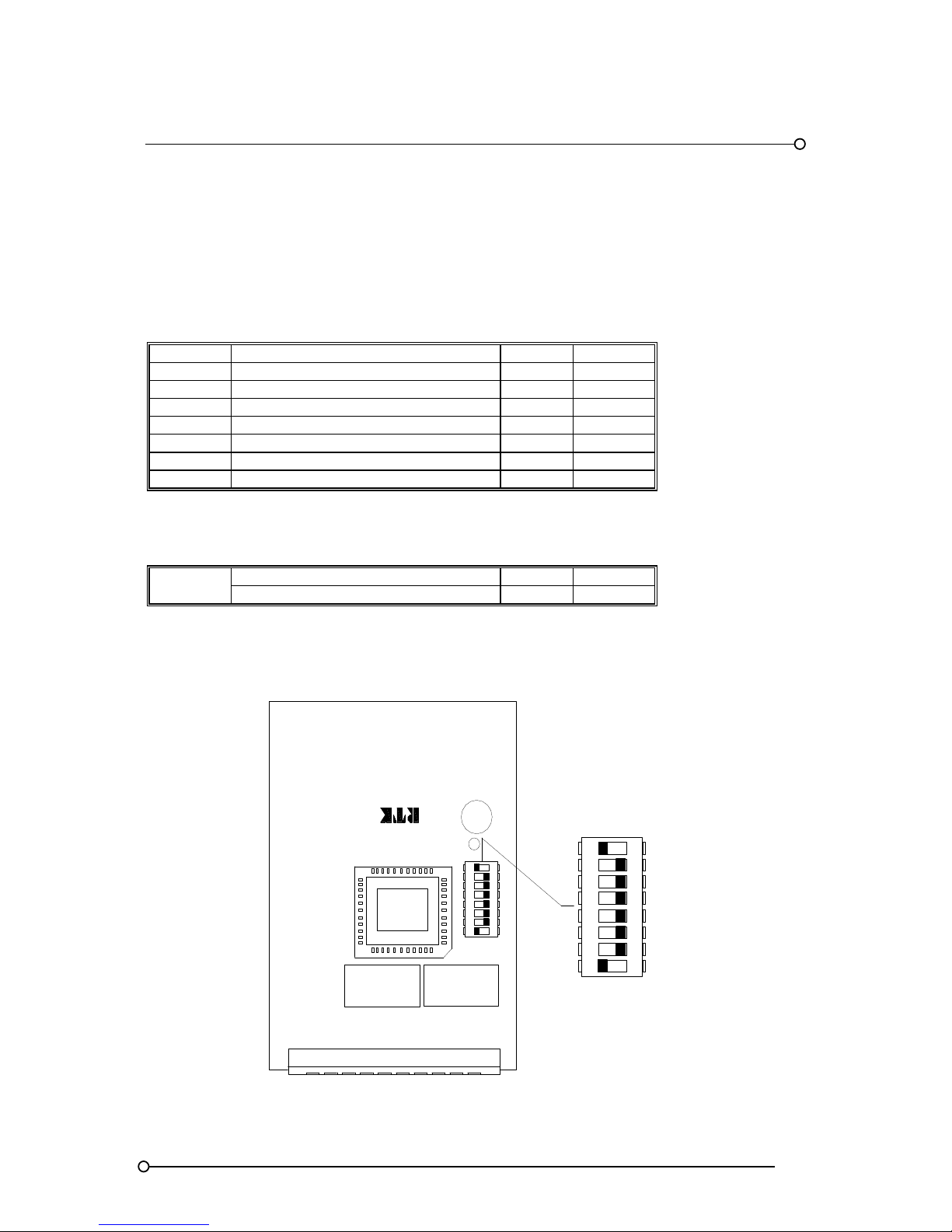
RTK Series 725 Annunciator
69
23. Alarm Card Address Settings
Dual Channel Alarm Card Address And Output Drive Type Settings
Before each card is placed within the annunciator a unique address No. has to be set using the
switches located on DIL switch SW1, which allows the programming module to communicate and
pass programming instructions to and from the associated alarm channels. When replacing an alarm
card the switches on DIL Switch SW1 must be set to match the card that is being removed.
SW1-* FUNCTION ON OFF
SW1-1 Set address Bit 1 1 0
SW1-2 Set address Bit 2 1 0
SW1-3 Set address Bit 3 1 0
SW1-4 Set address Bit 4 1 0
SW1-5 Set address Bit 5 1 0
SW1-6 Set address Bit 6 1 0
SW1-7 Set address Bit 7 1 0
23.1 Set Output Drive To Operate With Lamps or LED
SW1-8
Conventional filament lamps SW1-8 ON
Fit & forget LED assemblies SW1-8 OFF
Alarm Card DIL Switch SW1 Location
SW1 DIL SWITCH
OFFON
OFFON
A4506-*
RL2
RL1
ALARM CARD
1
2 3 4 5 6 7 8
1
2 3 4 5 6 7 8
Page 70

RTK Series 725 Annunciator
70
23.2 Alarm Card DIL Switch SW1 Address Settings
ADDRESS 64 32 16 8 4 2 1
NO. BINARY SW1-7 SW1-6 SW1-5 SW1-4 SW1-3 SW1-2 SW1-1
0 0000000 OFF OFF OFF OFF OFF OFF OFF
1 0000001 OFF OFF OFF OFF OFF OFF ON
2 0000010 OFF OFF OFF OFF OFF ON OFF
3 0000011 OFF OFF OFF OFF OFF ON ON
4 0000100 OFF OFF OFF OFF ON OFF OFF
5 0000101 OFF OFF OFF OFF ON OFF ON
6 0000110 OFF OFF OFF OFF ON ON OFF
7 0000111 OFF OFF OFF OFF ON ON ON
8 0001000 OFF OFF OFF ON OFF OFF OFF
9 0001001 OFF OFF OFF ON OFF OFF ON
10 0001010 OFF OFF OFF ON OFF ON OFF
11 0001011 OFF OFF OFF ON OFF ON ON
12 0001100 OFF OFF OFF ON ON OFF OFF
13 0001101 OFF OFF OFF ON ON OFF ON
14 0001110 OFF OFF OFF ON ON ON OFF
15 0001111 OFF OFF OFF ON ON ON ON
16 0010000 OFF OFF ON OFF OFF OFF OFF
17 0010001 OFF OFF ON OFF OFF OFF ON
18 0010010 OFF OFF ON OFF OFF ON OFF
19 0010011 OFF OFF ON OFF OFF ON ON
20 0010100 OFF OFF ON OFF ON OFF OFF
21 0010101 OFF OFF ON OFF ON OFF ON
22 0010110 OFF OFF ON OFF ON ON OFF
23 0010111 OFF OFF ON OFF ON ON ON
24 0011000 OFF OFF ON ON OFF OFF OFF
25 0011001 OFF OFF ON ON OFF OFF ON
26 0011010 OFF OFF ON ON OFF ON OFF
27 0011011 OFF OFF ON ON OFF ON ON
28 0011100 OFF OFF ON ON ON OFF OFF
29 0011101 OFF OFF ON ON ON OFF ON
30 0011110 OFF OFF ON ON ON ON OFF
31 0011111 OFF OFF ON ON ON ON ON
32 0100000 OFF ON OFF OFF OFF OFF OFF
33 0100001 OFF ON OFF OFF OFF OFF ON
34 0100010 OFF ON OFF OFF OFF ON OFF
35 0100011 OFF ON OFF OFF OFF ON ON
36 0100100 OFF ON OFF OFF ON OFF OFF
37 0100101 OFF ON OFF OFF ON OFF ON
38 0100110 OFF ON OFF OFF ON ON OFF
39 0100111 OFF ON OFF OFF ON ON ON
40 0101000 OFF ON OFF ON OFF OFF OFF
Page 71

RTK Series 725 Annunciator
71
Alarm Card DIL Switch SW1 Address Settings 41 To 80
ADDRESS 64 32 16 8 4 2 1
NO. BINARY SW1-7 SW1-6 SW1-5 SW1-4 SW1-3 SW1-2 SW1-1
41 0101001 OFF ON OFF ON OFF OFF ON
42 0101010 OFF ON OFF ON OFF ON OFF
43 0101011 OFF ON OFF ON OFF ON ON
44 0101100 OFF ON OFF ON ON OFF OFF
45 0101101 OFF ON OFF ON ON OFF ON
46 0101110 OFF ON OFF ON ON ON OFF
47 0101111 OFF ON OFF ON ON ON ON
48 0110000 OFF ON ON OFF OFF OFF OFF
49 0110001 OFF ON ON OFF OFF OFF ON
50 0110010 OFF ON ON OFF OFF ON OFF
51 0110011 OFF ON ON OFF OFF ON ON
52 0110100 OFF ON ON OFF ON OFF OFF
53 0110101 OFF ON ON OFF ON OFF ON
54 0110110 OFF ON ON OFF ON ON OFF
55 0110111 OFF ON ON OFF ON ON ON
56 0111000 OFF ON ON ON OFF OFF OFF
57 0111001 OFF ON ON ON OFF OFF ON
58 0111010 OFF ON ON ON OFF ON OFF
59 0111011 OFF ON ON ON OFF ON ON
60 0111100 OFF ON ON ON ON OFF OFF
61 0111101 OFF ON ON ON ON OFF ON
62 0111110 OFF ON ON ON ON ON OFF
63 0111011 OFF ON ON ON OFF ON ON
64 1000000 ON OFF OFF OFF OFF OFF OFF
65 1000001 ON OFF OFF OFF OFF OFF ON
66 1000010 ON OFF OFF OFF OFF ON OFF
67 1000011 ON OFF OFF OFF OFF ON ON
68 1000100 ON OFF OFF OFF ON OFF OFF
69 1000101 ON OFF OFF OFF ON OFF ON
70 1000110 ON OFF OFF OFF ON ON OFF
71 1000111 ON OFF OFF OFF ON ON ON
72 1001000 ON OFF OFF ON OFF OFF OFF
73 1001001 ON OFF OFF ON OFF OFF ON
74 1001010 ON OFF OFF ON OFF ON OFF
75 1001011 ON OFF OFF ON OFF ON ON
76 1001100 ON OFF OFF ON ON OFF OFF
77 1001101 ON OFF OFF ON ON OFF ON
78 1001110 ON OFF OFF ON ON ON OFF
79 1001111 ON OFF OFF ON ON ON ON
80 1010000 ON OFF ON OFF OFF OFF OFF
Page 72

RTK Series 725 Annunciator
72
Alarm Card DIL Switch SW1 Address Settings 81 To 120
ADDRESS 64 32 16 8 4 2 1
NO. BINARY SW1-7 SW1-6 SW1-5 SW1-4 SW1-3 SW1-2 SW1-1
81 1010001 ON OFF ON OFF OFF OFF ON
82 1010010 ON OFF ON OFF OFF ON OFF
83 1010011 ON OFF ON OFF OFF ON ON
84 1010100 ON OFF ON OFF ON OFF OFF
85 1010101 ON OFF ON OFF ON OFF ON
86 1010110 ON OFF ON OFF ON ON OFF
87 1010111 ON OFF ON OFF ON ON ON
88 1011000 ON OFF ON ON OFF OFF OFF
89 1011001 ON OFF ON ON OFF OFF ON
90 1011010 ON OFF ON ON OFF ON OFF
91 1011011 ON OFF ON ON OFF ON ON
92 1011100 ON OFF ON ON ON OFF OFF
93 1011101 ON OFF ON ON ON OFF ON
94 1011110 ON OFF ON ON ON ON OFF
95 1011111 ON OFF ON ON ON ON ON
96 1100000 ON ON OFF OFF OFF OFF OFF
97 1100001 ON ON OFF OFF OFF OFF ON
98 1100010 ON ON OFF OFF OFF ON OFF
99 1100011 ON ON OFF OFF OFF ON ON
100 1100100 ON ON OFF OFF ON OFF OFF
101 1100101 ON ON OFF OFF ON OFF ON
102 1100110 ON ON OFF OFF ON ON OFF
103 1100111 ON ON OFF OFF ON ON ON
104 1101000 ON ON OFF ON OFF OFF OFF
105 1101001 ON ON OFF ON OFF OFF ON
106 1101010 ON ON OFF ON OFF ON OFF
107 1101011 ON ON OFF ON OFF ON ON
108 1101100 ON ON OFF ON OFF OFF OFF
109 1101101 ON ON OFF ON ON OFF ON
110 1101110 ON ON OFF ON ON ON OFF
111 1101111 ON ON OFF ON ON ON ON
112 1110000 ON ON ON OFF OFF OFF OFF
113 1110001 ON ON ON OFF OFF OFF ON
114 1110010 ON ON ON OFF OFF ON OFF
115 1110011 ON ON ON OFF OFF ON ON
116 1110100 ON ON OFF ON OFF OFF OFF
117 1110101 ON ON ON OFF ON OFF ON
118 1110110 ON ON ON OFF ON ON OFF
119 1110111 ON ON ON OFF ON ON ON
120 1111000 ON ON ON ON OFF OFF OFF
Page 73

RTK Series 725 Annunciator
73
Alarm Card DIL Switch SW1 Address Settings 121 To 127
ADDRESS 64 32 16 8 4 2 1
NO. BINARY SW1-7 SW1-6 SW1-5 SW1-4 SW1-3 SW1-2 SW1-1
121 1111001 ON ON ON ON OFF OFF ON
122 1111010 ON ON ON ON OFF ON OFF
123 1111011 ON ON ON ON OFF ON ON
124 1111100 ON ON ON ON ON OFF OFF
125 1111101 ON ON ON ON ON OFF ON
126 1111110 ON ON ON ON ON ON OFF
127 1111111 ON ON ON ON ON ON ON
Page 74
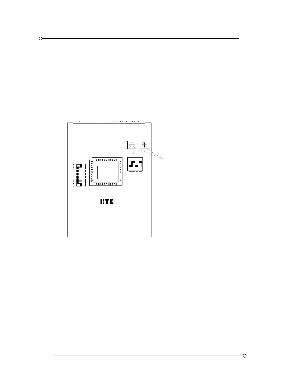
RTK Series 725 Annunciator
74
24. Customer Adjustable Response Times
If specified at the time of ordering alarm cards can be supplied with single-turn potentiometers that
allow the user to set the reponse time of each input.
Option AD1 = 5 – 50 ms
Option AD2 = 20ms - 2 seconds
Option AD3 = 5ms – 5 seconds
ON
RL2
4
8
6
7
5
OFF
3
2
1
ALARM CARD
RL1
A4506-*
VR2 VR1
CH2 CH1
CARD MODEL NO CB5674POP1
RESPONSE TIME
ADJUSTMENT
1 2
3
4 OFF
ON
SW1
SW2
NC DM DMNC
1 2
To access the individual alarm card the plastic cover plate on the rear of the associated cell must be
removed by squeezing the lock-in tabs on either side of the cover.
The alarm card can then be removed to allow adjustments to be made to VR1 (Channel 1) and VR2
(Channel 2) as required.
The standard adjustment is in the range 5ms to 50ms turning the trim pot in a clockwise direction to
increase the response time.
Page 75
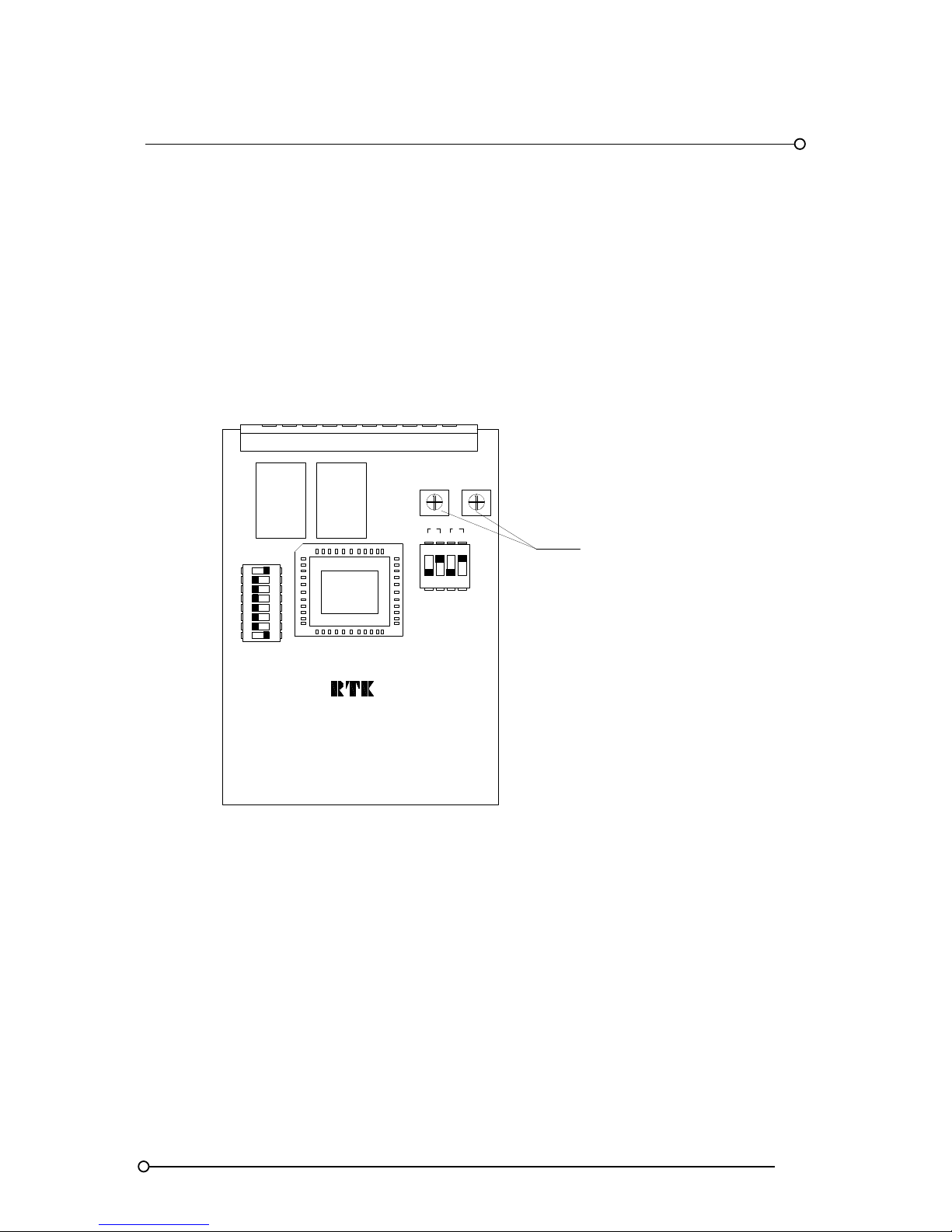
RTK Series 725 Annunciator
75
Return to Normal Delay Period
In standard applications any delay period set for alarm initiation is also applied to the return to normal
state.
For example if a 5 second delay is set, the alarm will not activate until the input has been in the
abnormal state for a minimum of 5 seconds.
If the alarm returns to normal the same delay period of 5 seconds will apply before the alarm state
returns to normal.
In some applications Customers prefer the alarm to have a delay before the alarm activates but as
soon as the input returns to normal they require the alarm to return to the non alarm condition.
ON
RL2
4
8
6
7
5
OFF
3
2
1
ALARM CARD
RL1
A4506-*
VR2 VR1
CH2 CH1
CARD MODEL NO CB5674POP1
RESPONSE TIME
ADJUSTMENT
1 2
3
4 OFF
ON
SW1
SW2
NC DM DMNC
1 2
Switch SW2 is used to set :-
SW2 – 1 & 3 are used to set the Input state to Normally Open or Normally Closed
SW2 – 2 & 4 are used to set the Delay Mode
The Delay Mode can be set, (OFF position), to provide the same delay period for the
initiation and return to normal states or
The Delay Mode can be set, (ON position), to remove the delay on the return to normal state.
Page 76

RTK Series 725 Annunciator
76
SW2
1 2 3 4
When using AD* options, on P725 Annunciator supplied after March 2009 Switch SW2 is available
on each (2) channel alarm card to allow the user to set the input state to normally open or normally
closed and to set the return to normal delay period.
Input State
SW2 positions 1 and 3 on each (2) channel alarm card allow the user to set the input state as
follows:-
SW2-1 – ON = Channel 1 set to Normally Closed
SW2-1 – OFF = Channel 1 set to Normally Open
SW2-3 – ON = Channel 2 set to Normally Closed
SW2-3 – OFF = Channel 2 set to Normally Open
IMPORTANT NOTE:-
Please ensure Function F1 is set to OFF state on all channels or settings will be overwritten.
Return to Normal Delay (Delay Mode)
When using AD* options, on P725 Annunciators supplied after March 2009 SW2 positions 2 and 4
allow the Customer to select if they require the return to normal to have the same delay period as
alarm activation or if the require the alarm to return to the normal state as soon as the input contact
returns to normal.
SW2-2 – ON = Channel 1 will return to normal as soon as the Input returns to normal
SW2-2 – OFF = Channel 1 will have the same return delay period as the activation delay
SW2-4 – ON = Channel 2 will return to normal as soon as the Input returns to normal
SW2-4 – OFF = Channel 2 will have the same return delay period as the activation delay
Page 77

RTK Series 725 Annunciator
77
25. Systems with Serial Communication
Introduction
As an option the annunciator can be supplied with an internal serial communications card which is
switch selectable to use modbus ASCII or modbus RTU protocol . This allows the annunciator to
interface to 3rd party devices such as PLC's, DCS, industrial computers, SCADA packages etc. The
annunciator is RS485 / RS422 compatible and can easily be co nverted to RS232 using a suitable
external converter. As standard the annunciator acts as a 'slave' device, but can be configured to act
as master when communicating to slave P725 annunciators.
Bi-Directional Communications
The bi-directional communications card allows the unit to read and write data to each alarm window,
which provides contact status, window illumination control/status, and pushbutton information. Each
channel within the annunciator can be set to alarm from a hard wired signal input or via the serial
communications as required.
Configuration
The baud rate, parity and protocol are selected by changing DIL switch settings on the
communications card as described later in this section.
Address Selection
Each annunciator is set with a unique address from 0 to 63, which allows up to 64 separate
annunciators to be connected in a single RS485 multi-drop loop. RTK can also supply
comprehensive alarm monitoring and logging software if required.
Character Format
ASCII 7 data, 1 start, 1 stop, 1 parity
RTU 8 data, 1 start, 1 stop, 1 parity
Message Format
In accordance with the standard modbus protocols, all data exchanges are assumed to comply
strictly with these standards. ASCII transmissions will start with a colon and end with longitudinal
redundancy check (LRC), carriage return and line feed. RTU transmissions will not use framing
characters and will incorporate a cyclic redundancy check (CRC).
For further details please refer to the "Modicon modbus protocol reference guide” available from
Modbus-IDA www.modbus.org
Fault Indication
If communications cannot be established within a specified time-out period (typically 10 seconds)
then the watchdog relay on the communications card will trip and, if fitted, the "communications fault"
window will illuminate. This indicates there is a communications fault either with the external device
or with the integral alarm cards within the annunciator. Because the system continually attempts to
regain communications it will self-recover as soon as communication is re-established.
Page 78

RTK Series 725 Annunciator
78
P725 to P725 Connections
For applications where local and remote annunciators are required two or more P725 annunciators
can be interconnected. In the normal situation one of the annunciators will monitor the standard voltfree alarm contacts or voltage inputs and indicate the alarms as normal. This alarm information is
then transmitted on the serial communications to another P725 annunciator using either two or four
wires for the communications. These systems are interconnected as shown later in this section.
System 9000TS To P725 Annunciator
The System9000TS Annunciator from RTK Instruments can also be used as described above to
monitor a number of alarm contacts and transmit the information via the serial communications to a
remote P725 annunciator. The System9000TS can optionally have a display to indicate alarm
information or simply operate as a data gathering and transmission device. Please refer to our sales
office for further information on these systems.
Modbus Communications
Full details on how to use modbus ASCII and modbus RTU protocols are not given within this manual
as they are well covered by more specialised manuals. A brief overview of the main features is
shown below.
Modbus Function Codes
The function code field tells the addressed 'slaves' what function to perform. The only relevant
function codes when communicating to the P725 annunciator are as follows:-
03 Read register This reads 16 bit data registers containing alarm information
06 Write register Writes data to 16 bit register. This data request can be used
as an alternative alarm input source.
Error Check
The error check is either LRC (Longitudinal redundancy check) or CRC (Cyclic redundancy check)
depending on whether ASCII or RTU modbus is selected.
Software
RTK Instruments can supply comprehensive monitoring software for use with the 725 Series alarm
annunciator. This can be configured as an alarm/event management system with user generated
custom displays to monitor plant wide system operation.
Page 79
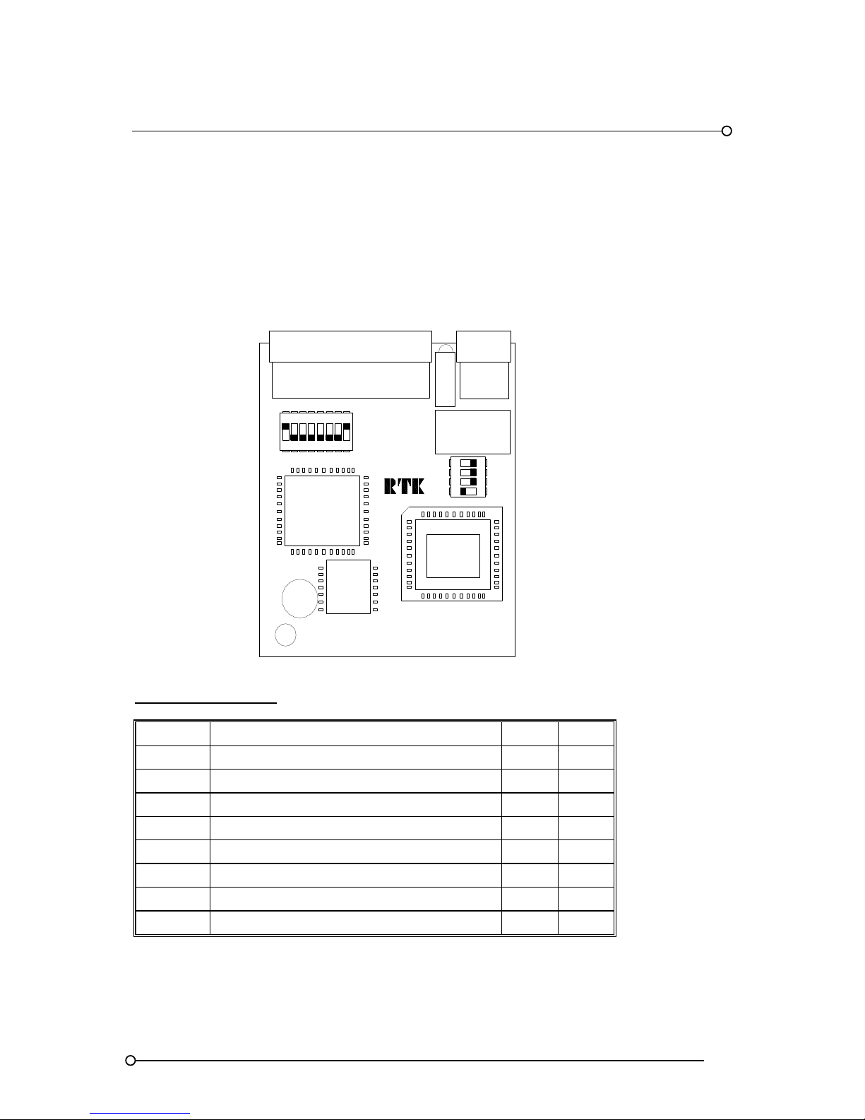
RTK Series 725 Annunciator
79
26. Serial Communication Card
The series 725 Series Alarm Annunciator can be fitted with a serial communications card, which will
provide an RS485 port to connect to external equipment.
A number of features on this card are DIL- switch selectable as described in the following section.
Position Of DIL Switches On Communications Card
ON
4 8675
OFF
3
21
A4506-*
CARD MODEL NO CB4468POP1
2
1
43
ON
OFF
SW1
SW2
COMMUNICATION CARD
Switch SW1 Functions
SW1-* FUNCTION ON OFF
SW1-1 Address bit 1 1 0
SW1-2 Address bit 2 1 0
SW1-3 Address bit 3 1 0
SW1-4 Address bit 4 1 0
SW1-5 Address bit 5 1 0
SW1-6 Address bit 6 1 0
SW1-7 Enable Remote Serial PB Control ON
SW1-8 Enable outputs for bulb drive ON
Page 80
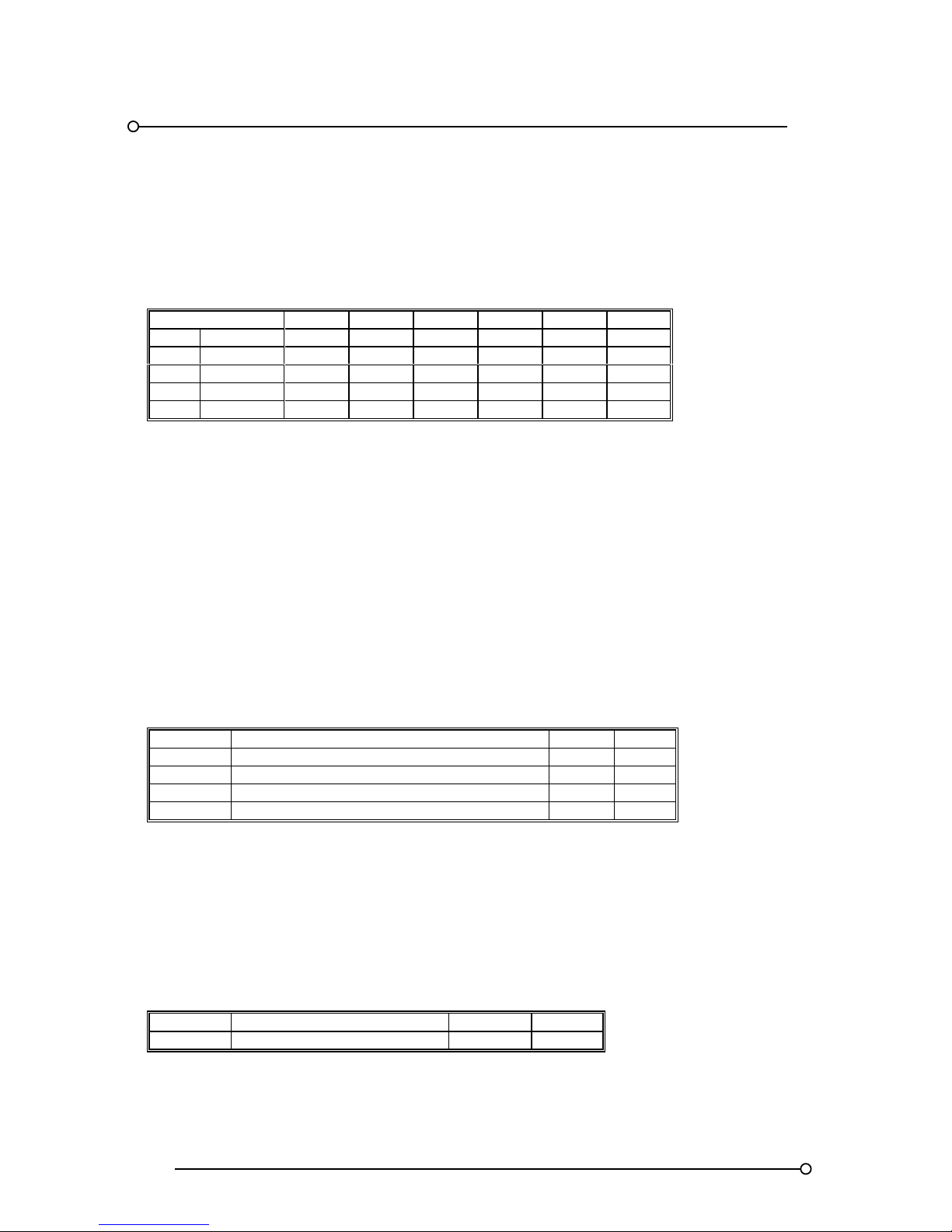
RTK Series 725 Annunciator
80
Serial Interface Card Address selection
Each annunciator needs to have a node address selected which must be between 0 and 63. It is this
address that makes the annunciator unique and allows the external equipment to communicate to a
defined annunciator within a multi-drop system. The following examples are provided as a guide to
setting the address
ADDRESS 32 16 8 4 2 1
NO. BINARY SW1-6 SW1-5 SW1-4 SW1-3 SW1-2 SW1-1
0 0000000 OFF OFF OFF OFF OFF OFF
1 0000001 OFF OFF OFF OFF OFF ON
2 0000010 OFF OFF OFF OFF ON OFF
3 0000011 OFF OFF OFF OFF ON ON
Enable Remote Serial Pushbutton Control
In systems connected to a remote device via the communications link it is sometimes a requirement
for the pushbutton control to be provided externally via the communications port.SW1-7 should be
set to the ON position in applications which require a slave P725 to mimic the functions of a master
unit. The local pushbutton will remain operational even if this feature is enabled.
Lamp or LED Outputs
SW1-8 should be set to the ON position in applications using filament lamps to display the serial
communication watchdog alarm within the annunciator (typically located above the integral
pushbutton module).
SW1-8 should be set to the OFF position in applications using “fit & forget” LED assemblies in place
of filament lamps.
SW2 Selection
The table below indicates additional communication parameters that can be set by the user.
SW2-* FUNCTION ON OFF
SW2-1 Set communication baud rate 4800 9600
SW2-2 Set Modbus protocol type RTU ASCII
SW2-3 Set parity type ODD EVEN
SW2-4 Set as Modbus master or slave Master Slave
All switches are factory set to off as default so it is only necessary to make changes if the standard
parameters do not suit the particular configuration.
The master/slave selection is only used when a P725 annunciator is using the serial communication
link to communicate to another P725 annunciator in a master / slave configuration as detailed earlier.
Option MOD C7 High Speed Communication Version
As an option the Communication port can be supplied as a high speed version with the following
selectable speeds.
SW2-* FUNCTION ON OFF
SW2-1 Set communication baud rate 19200 38400
Page 81
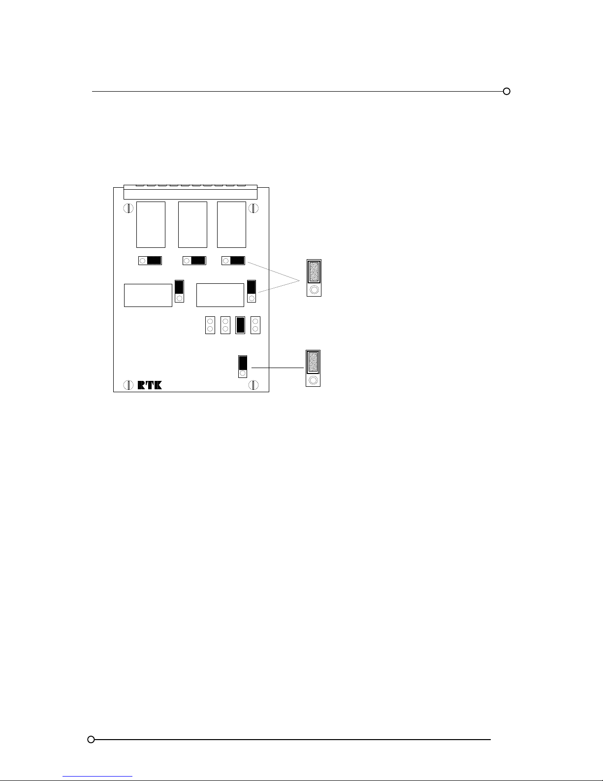
RTK Series 725 Annunciator
81
SPR Card Settings
On systems using serial communications Link LK10 on the SPR card should be set to Comm’s as
shown below
Pt No CB4642POP1
N/C
RL2 - HNB
HORN RELAY
RL3
GPA
GROUP
RELAY
RL5
MULT.
FUNCT.
RELAY
LK5
RL4 - GPB
GROUP RELAY
N/O
LK4
N/O
N/C
N/C
N/O
LK3
1ST
COMM'S
STD
LK10
RBHGP WD
COMM'S
STD
CONTACT SET
NORMALLY CLOSED
NORMALLY OPEN
RL1
HNA
HORN
RELAY
LK6
LK2
LK8
LK7
LK9
N/O
LK1
N/C
N/O
N/C
N/O
N/C
Page 82
RTK Series 725 Annunciator
82
27. Serial Communication Port
This section describes the process of reading from and writing data to a P725 slave annunciator, and
also the different types of data interchange possible. The tables below show the standard message
formats for data interchange, for both ASCII and RTU protocols.
ASCII tables. Each character represents 7 bit binary data in ASCII format with the
exception of the characters in brackets, which should be considered as one
character.
X represents a character with more than one possible value.
All characters are framed with 1start bit, 1parity bit and 1 stop bit.
RTU tables. Each character represents 8 bit binary data in hexadecimal format.
Y represents a character with more than one possible value.
All characters are framed with 1 start bit, 1parity bit and 1 stop bit.
Read Request – Master
ASCII
START ADDRESS FUNCTION
REGISTER
ADDRESS
NO OF
REGISTERS
ERROR
CHECK
STOP
: XX 03 XXXX 0001 XX [LF] [CR]
RTU
START ADDRESS FUNCTION
REGISTER
ADDRESS
NO OF
REGISTERS
ERROR
CHECK
STOP
ELAPSED TIME 3
½
CHARACTERS
MIN
Y 3 YY 01 YY
ELAPSED TIME
3 ½
CHARACTERS
MIN
Read Response - P725 Slave
ASCII
START ADDRESS FUNCTION
BYTE
COUNT
DATA
ERROR
CHECK
STOP
:
XX 03 02 XXXX XX [LF] [CR]
RTU
START ADDRESS FUNCTION
BYTE
COUNT
DATA
ERROR
CHECK
STOP
ELAPSED
TIME 3 ½
CHARACTERS
MIN
Y 3 2 YY YY
ELAPSED
TIME 3 ½
CHARACTERS
MIN
Page 83
RTK Series 725 Annunciator
83
Write Request/Response
Master write request and P725 slave write response, are the same.
ASCII
START ADDRESS FUNCTION
REGISTER
ADDRESS
DATA
ERROR
CHECK
STOP
: XX 06 XXXX XXXX XX [CR] [LF]
RTU
START ADDRESS FUNCTION
REGISTER
ADDRESS
DATA
ERROR
CHECK
STOP
ELAPSED
TIME 3 ½
CHARACTERS
MIN
Y 6 YY YY YY
ELAPSED
TIME 3 ½
CHARACTERS
MIN
Address
The address field, in the range O to 63, should be set to match the address set on DIL switch SW1
on the save P725 communication card
Register Address
The register address field contains the address of data within the P725 slave.
REGISTER ADDRESS CHANNEL NO TYPE
0 1 Data
1 2 Data
2 3 Data
255 256 Data
256 Pushbutton Data
Data
The data field uses 16 bits. The information it contains is dependent on the type of data interchange
being performed i.e. read or write, register address, status of functions 16, 17 and the status of SW1
Position 7 on the communications board. The table below lists the main types of data interchange
and the various settings required. It is assumed in the table below that remote data originates from a
master, and local data from a P725 slave.
DATA INTERCHANGE
SETTINGS
F16 F17 SW1-7
Read local channel input OFF X X
Read local channel logic X OFF X
Read local channel input + logic OFF OFF X
Read local pushbutton X X X
Write remote channel input ON X X
Write remote channel logic X ON X
Write remote channel input + logic ON ON X
Write remote pushbuttons X X ON
Page 84

RTK Series 725 Annunciator
84
Channel Data
The following table shows the name, function, and relative position of data bits in the data field for a
read response or write request of alarm channel data.
BIT DATA
LOWEST WORD 0 Input state
1 First up
2 Acknowledge
3 Input latch
4 Ringback
5 Not used
6 Not used
7 Not used
HIGHEST WORD Not Used
Channel data request register address 0 - 255
Input State-BIT 0
0 = Normal, 1 = Abnormal
Read response + F16 deselected – Indicates status of local alarm contact
Read response + F16 selected – Indicates status of input bit
If the alarm contact is in the alarm state then this bit will be one. This has no relation to the actual
contact being open or closed which is set using the function number F1, it simply states that the
contact is in the alarm state.
First-Up-BIT 1
If this bit is set to one then this channel is a first-up alarm. If multiple first-up groups are used it will be
possible to have multiple first-up alarms. The serial communications transmits no details on alarm
grouping so this would need to be done externally if required.
Acknowledged-BIT 2
When an alarm channel is acknowledged the visual and audible states are normally changed. When
this bit is set to one it indicates that the alarm channel has been acknowledged.
Input Latch-BIT 3
Each alarm channel has in integral latch that is normally set when an alarm occurs and does not
reset until the alarm is acknowledged and also reset. This bit will indicate that this latch is on when
set to one which means there is still an alarm present that has not been acknowledged and reset.
Ringback-BIT 4
With this sequence set further indication will show that the alarm channel has returned to normal and
can be reset. If this bit is set to one then the channel is in ringback mode.
Page 85

RTK Series 725 Annunciator
85
Control Functions - (Pushbuttons)
All the control functions with the exception of sleep and lamp test can be written to or read from the
P725 slave. The following table shows the name, function, and relative position of data bits in the
data field for a read response or write request of pushbutton data.
BIT DATA
LOWEST WORD 0 Test
1 Acknowledge
2 Reset
3 Not used
4 Not used
5 Not used
6 Not used
7 Not used
HIGHEST WORD Not used
Pushbutton Address 256
The first three data bits are used to indicate the pushbutton action.
Their relationship to the pushbutton action is summarised in the table below.
BITS
CONTROL FUNCTION Test (0) ACK (1) Reset (2)
Test 1 0 0
Ack 0 1 0
Reset 0 0 1
First-up reset 0 1 1
System test 1 0 1
Mute 1 1 1
Read of multiple channels
In applications where you need to read or write the status of the input channel without any
information on the full alarm status it is possible to transmit 16 channels in a single read/write
cycle. This information can be read (Modbus Function 3) or written to (Modbus Function 6)
and starts at address 2000 for channels 1 to 16 (bit 0 = channel 1, bit 15 = channel 16),
address 2001 for channels 17 to 32 (bit 0 = channel 17, bit 15 = channel 32) and so on.
On Systems supplied after May 1st 2006 the user is also able to read or write the latch state
of the input channel and transmit 16 channels in a single read/write cycle. This information
can be read (Modbus Function 3) or written to (Modbus Function 6) and has a starting
address of 2016 for channels 1 to 16 (b it 0 = channel 1, bit 15 = channel 16), address 2017
for channels 17 to 32 (bit 0 = channel 17, bit 15 = channel 32) and so on.
Page 86
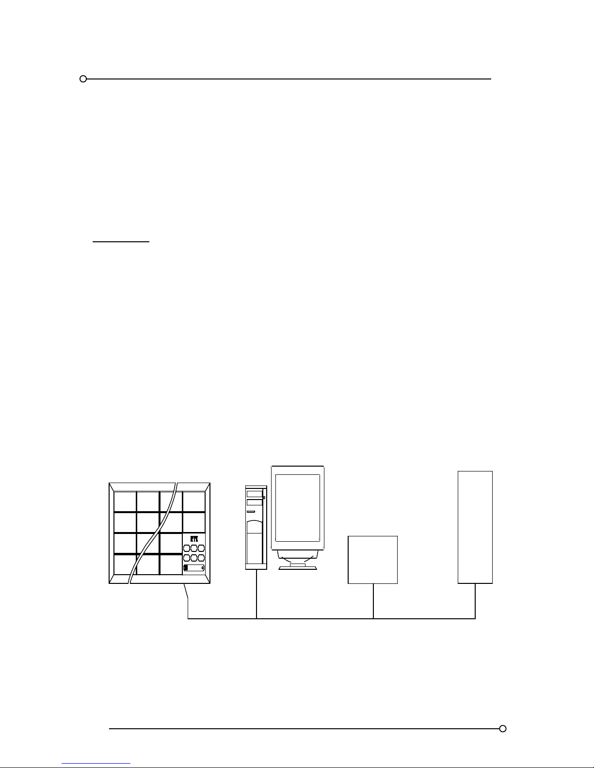
RTK Series 725 Annunciator
86
28. Systems Linked To 3rd Party Devices
General
Using the advanced communications facilities on the series 725 annunciator, it is possible to c onnect
the unit to a variety of 3rd party devices to monitor or control the alarm annunciator.
Any 3rd party device equipped with either a RS485 or a RS232 port using modbus protocol can be
connected to the P725 annunciator.
Please note:-
If the RS232 port of the 3rd party device is used a RS485 / 232 converter will be required.
The P725 annunciator always operates as a slave device and it is therefore only able to read and
write following requests from the master device.
Various parameters of the communications are user configurable using DIL switches on the
communications card.
In larger applications up to 63 separate annunciators can be connected to a single communication
network to allow remote monitoring by 3rd party equipment.
In addition to the annunciation RTK can also supply suitable alarm management software pre-
installed onto a single computer or as part of a complete plant wide alarm management system.
P725 Connected To 3rd Party Equipment
PLC
DCS/ESD
PC
POWER
LAMP
TEST
ACK RESET
SYST
TEST
MUT E
FIRST
RESET
P725
Page 87
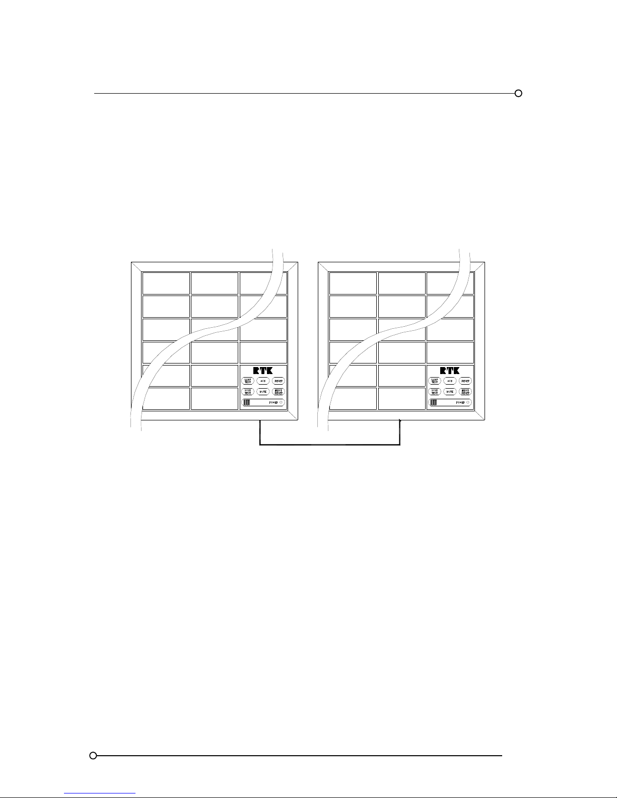
RTK Series 725 Annunciator
87
29. P725 To P725 Serial Links
Local And Remote Systems Linked Via Communications
In applications that require local panel alarms to be duplicated or summarised in a central control
room each P725 can be supplied with a serial interface card which allows RS485 communication
between units using Modbus protocol.
As an example a local annunciator can be hard wired to the alarm contacts and the alarm information
can be transmitted over the RS485 communications link to a slave P725 unit mounted in a control
room or monitoring station.
RS485 LINK BETWEEN
P725 ANNUNCIATORS
SLAVEMASTER
Each Serial Communication card is equipped with a watchdog relay and this relay will change state if
any errors in the internal or external communication are detected.
In larger applications multiple P725 Annunciators can be connected to a single P725 Annunciator
used for central monitoring. Each annunciator in the scheme will require the optional serial interface
card.
The key advantage with units configured in this manner is the central monitoring annunciator only
requires 24VDC logic power and a 4 core RS485 cable to function.
In this example functions F16 and F17 are used to configure each unit to either transmit or receive
serial data as required.
Please note:- one of the devices must be set as a master.
Page 88
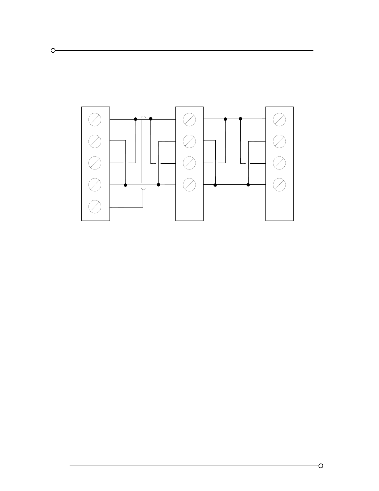
RTK Series 725 Annunciator
88
Communication Link Wiring Details
8
7
6
5 5
6
7
8
5
6
7
8
5
6
7
8
SCR
RXa
RXb
TXa
TXbTXb
TXa
RXb
RXa
TXb
TXa
RXb
RXa
P725 MASTER P725 SLAVE P725 SLAVE
Page 89

RTK Series 725 Annunciator
89
30. Commissioning
A qualified technician properly trained and authorised to work with this type of equipment should
carry out commissioning and servicing operations. The following procedure is a summary of the
steps normally taken when installing an alarm system. This is the absolute minimum requirement and
will generally be supplemented by a number of additional checks relating to the particular application
and installation.
STEP FUNCTION
1 Check all external customer connections to the annunciator are free from earth faults.
2 Ensure the annunciator has been correctly earthed using appropriate sized cable.
3 Check that all customers wiring added during installation is secure and correctly wired.
4 Apply a 24vdc logic supply and check that the power on LED illuminates correctly.
5
Press the system test pushbutton to check that all active alarm channels flash and the
audible alarm sounds in accordance with the programmed sequence.
6 Press the remaining pushbuttons required to control the programmed sequence.
7
Refer to the section on programming and check that all of the required functions have been
correctly set.
8
Initialise each channel one by one from the field device to check that the laser printed film
legend and filter colour matches the associated process.
Page 90
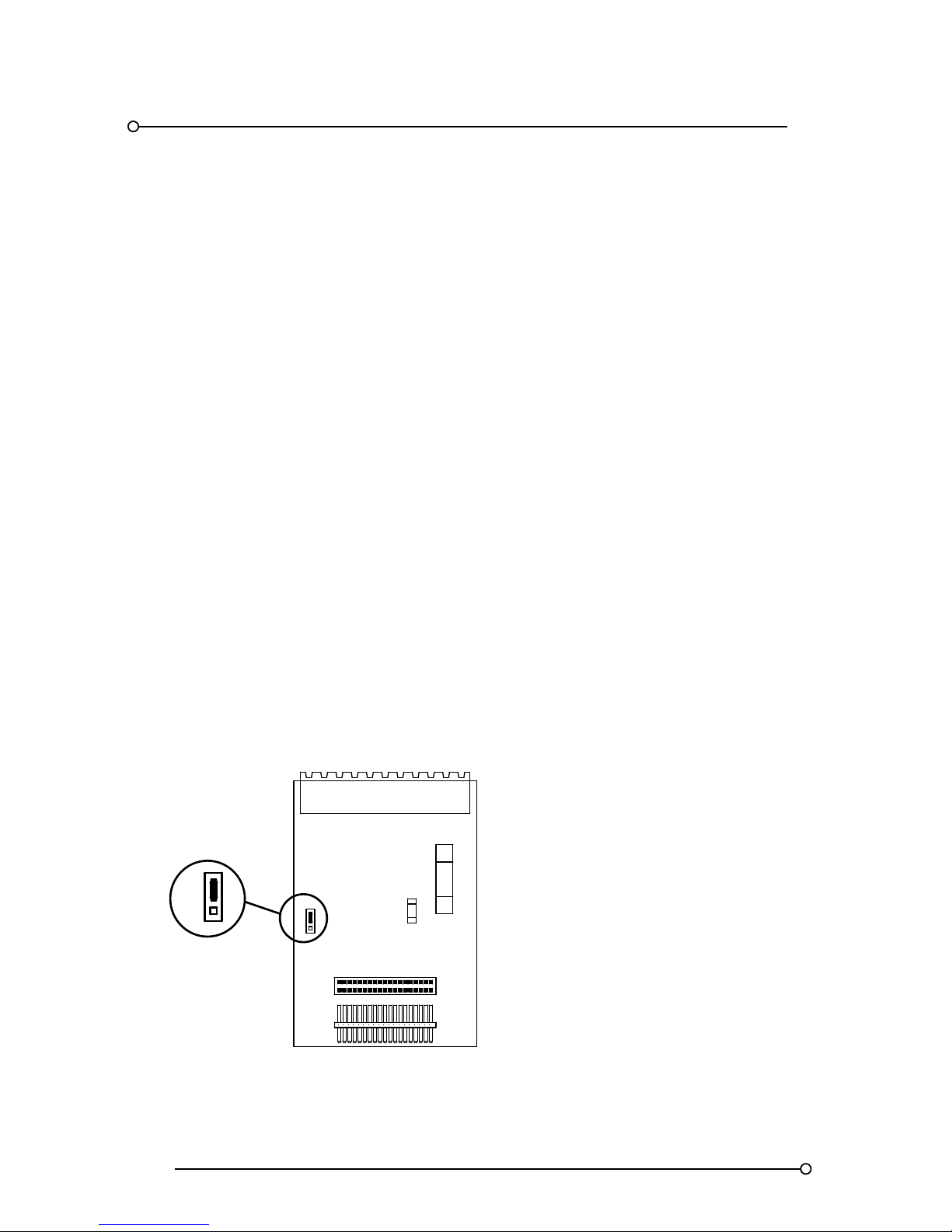
RTK Series 725 Annunciator
90
31. Maintenance
31.1 No Special Tools
All normal maintenance and programming is carried out from the front of the annunciator without the
use of special tools. Filter and film legend changes and lamp and LED replacement are all
undertaken by unclipping the front filter assembly.
31.2 Removing Filter Assemblies
See Section 3.4.
31.3 Changing Film Legend
See Section 3.4.
31.4 Changing Bulbs/LED Assemblies
After removal of the filter assembly the lamp holder will be visible. A lamp test pushbutton can be
pressed to ascertain which lamps have failed; it is then a simple matter to remove the faulty bulbs.
These bulbs are standard 10mm glass wedge and can be removed by pulling directly away from the
lamp holder with a pair of pliers or the standard lamp remover supplied with the unit. Replace by
reversing the procedure, taking care that the wedge base is correctly located in the socket before
pressing home. The LED assemblies are removed and replaced in exactly the same way accept that
the glass wedge is replaced with a small PCB connecting tag. The LED’s are not polarised so can be
fitted in either orientation.
31.5 Fuse Replacement
Two fuses protect the overall system, one protects the supply and motherboard (F1) and the other
protects the feed to the alarm contacts (F2). These are both situated on the supply card, which is
fitted in the SPR module. The location of the two fuses is shown below. Take care to replace fuses
with fuses of exactly the same type. Spare fuses are supplied with all annunciator shipments.
31.6 Position Of Fuses On The Supply Card
10 A/T
F1
1 A/F
F2
FR
SP
FR
SP
Page 91

RTK Series 725 Annunciator
91
32. Spare Parts Description
Alarm Card Types
There are 4 basic types of dual channel alarm cards however earlier version P725 Annunciators
used metal casing and the cards were slightly smaller than the latest versions which are housed in
plastic enclosures. The list below details both types.
OLDER VERSIONS (Metal Case Annunciator)
PART NO DESCRIPTION USED ON
CB3975POP1 2 Channel alarm card
Large, Medium and Small window versions
Located in the upper slot of the cell
CB3975POP2
2 Channel alarm card with repeat
relays
Large, Medium and Small window versions
Located in the upper slot of the cell
CB3975POP3 2 Channel alarm card
Small window versions
Located in the lower slot of the cell
CB3975POP4
2 Channel alarm card with repeat
relays
Small window versions
Located in the lower slot of the cell
CB3975POP5
2 Channel alarm card with
communications
Large, Medium and Small window versions
Located in the upper slot of the cell
CB3975POP6
2 Channel alarm card with
communications and repeat relays
Large, Medium and Small window versions
Located in the upper slot of the cell
CB3975POP7
2 Channel alarm card with
communications
Small window versions
Located in the lower slot of the cell
CB3975POP8
2 Channel alarm card with
communications and repeat relays
Small window versions
Located in the lower slot of the cell
CURRENT VERSIONS (Plastic Case Annunciator)
PART NO DESCRIPTION USED ON
CB5674POP1 2 Channel alarm card
Large, Medium and Small window versions
Located in the upper slot of the cell
CB5674POP2
2 Channel alarm card with repeat
relays
Large, Medium and Small window versions
Located in the upper slot of the cell
CB5674POP3 2 Channel alarm card
Small window versions
Located in the lower slot of the cell
CB5674POP4
2 Channel alarm card with repeat
relays
Small window versions
Located in the lower slot of the cell
CB5674POP5
2 Channel alarm card with 4 x first
up groups
Large, Medium and Small window versions
Located in the upper slot of the cell
CB5674POP6
2 Channel alarm card with 4 x first
up groups and repeat relays
Large, Medium and Small window versions
Located in the upper slot of the cell
CB5674POP7
2 Channel alarm card with 4 x first
up groups
Large, Medium and Small window versions
Located in the lower slot of the cell
CB5674POP8
2 Channel alarm card with 4 x first
up groups and repeat relays
Large, Medium and Small window versions
Located in the lower slot of the cell
Signal Supply Voltages
All card types are supplied suitable for operation from one of the following signal supply voltages
24VDC, 48VDC, 125VDC or 250VDC. The voltage levels are screen printed onto each card and one
of the voltages will be ticked to indicate which version has been supplied. Alarm cards plug into the
rear of the annunciator and once inserted automatically connect to a pre-tested lamp / LED display
motherboard.
Page 92
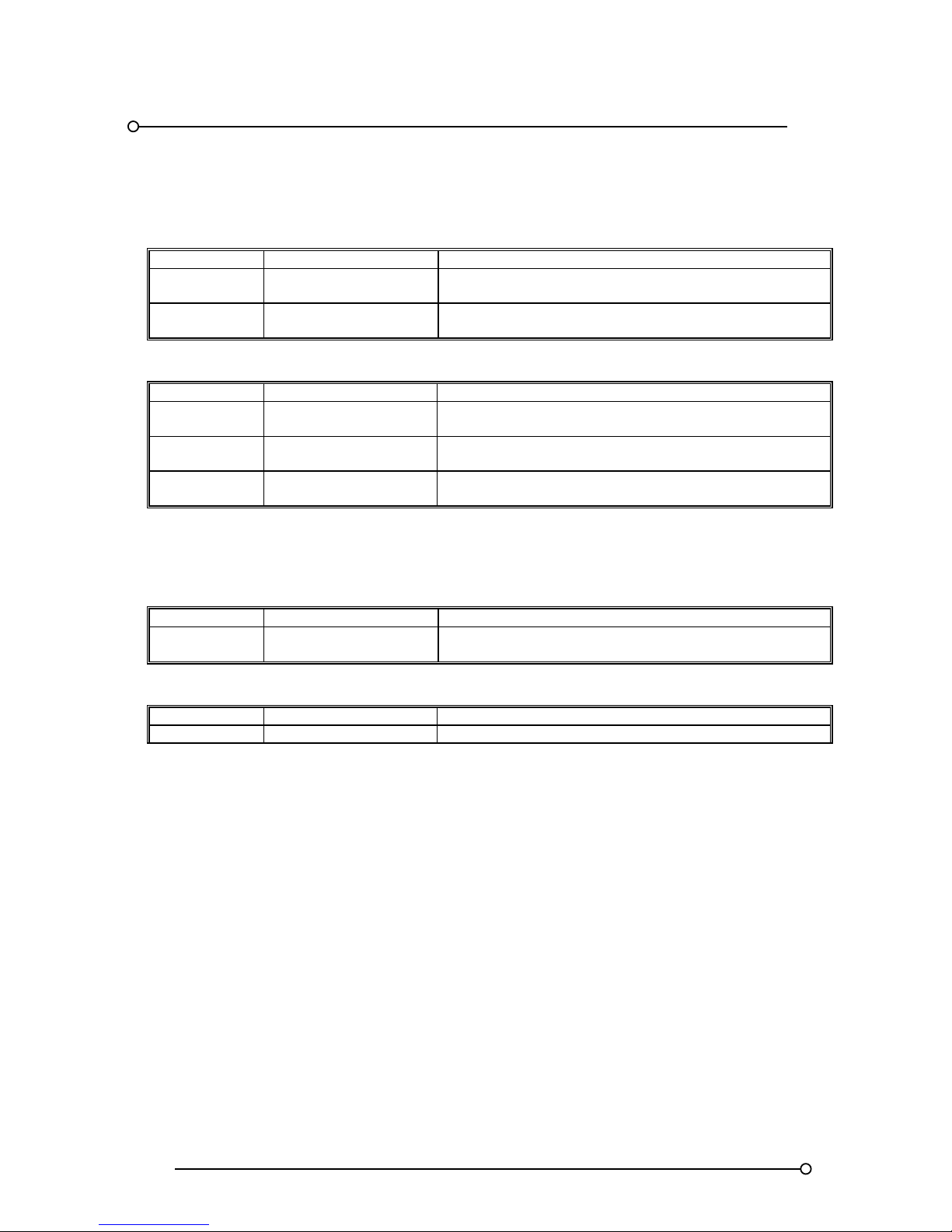
RTK Series 725 Annunciator
92
SPR Dual Card Assembly (Supply And Relay Card)
Current Versions
PART NO DESCRIPTION USED ON
CB7080POP SPR supply card
Replaced the original CB4190POPcard in plastic version
annunciator cabinets from Dec 2006 onwards
CB7081POP1 SPR relay card
Replaced the CB4210POP card in plastic version
annunciator cabinets from Dec 2006 onwards
Older Versions
PART NO DESCRIPTION USED ON
CB4190POP SPR supply card
Earlier versions used to distribute and fuse logic and
signal supplies within the annunciator
CB4210POP SPR relay card
Earlier versions used to provide the 5 common relay
functions. (Dual horn and group plus multifunction relays)
CB4642POP1 SPR relay card
Replaced the original CB4210POP card in plastic version
annunciator cabinets
Communications Card
Current Version
PART NO DESCRIPTION USED ON
CB6357POP1 Communications card
Replaced the original CB4468POP1 card in plastic
version annunciator cabinets from Dec 2006 onwards
Older Version
PART NO DESCRIPTION USED ON
CB4468POP1 Communication card Earlier version communication card
Pushbutton Assembly
Part no P725-TAR
Incandescent bulb version
Part no LP-28V-004 (supplied in packs of 10)
LED version
LED Assembly Part no P725LED-XX (where xx is the colour)
RD-Red
YW-Yellow
AM-Amber
WT-White
BL-Blue
GN-Green
Page 93

RTK Series 725 Annunciator
93
33. Other RTK Products
RTK Instruments Ltd are fully ISO9001:1994 approved and manufacture a comprehensive range of
complementary products from our factory in Knaresborough N. Yorkshire for use in the Industrial
Control and Instrumentation field per the summary list provided below.
All standard products come complete with a 5 year guarantee
Sequential event recorder
Alarm management systems
Programmable remote logic alarm systems
Hazardous area alarm systems
Trip amplifiers
Trip monitoring systems
Signal isolators
Multi-output isolators
Signal converters
Frequency converters
Tachometers and inverse tachometers
Universal panel meters
Large character displays
Power supplies
Loop powered isolators and displays
Intrinsically safe alarm and status display products including:LED beacons
Sounders
Led clusters
Please ring the sales office on 0044 (0) 1423 580 500 for latest product information or visit our web
site www.rtkinstruments.com
Page 94

RTK Series 725 Annunciator
94
34. EC DECLARATION OF CONFORMITY
This is to certify that the P725 Alarm Annunciator
Manufactured by:
RTK INSTRUMENTS LTD
ST JAMES BUSINESS PARK
KNARESBOROUGH
NORTH YORKSHIRE
HG5 8PJ
Conforms with the protection requirements of Council Directive 89/336/EEC, amended by 92/31/EEC
and 73/23/EEC on the approximation of the laws of the Member State relating to electromagnetic
compatibility and low voltage directive
Representative samples of the P725 Alarm Annunciator have been tested/evaluated in accordance
with:-
BS EN 61000-6-4:2001
Electromagnetic Compatibility
Generic Emission Standard
Part 2: Industrial Environment
BS EN 61000-6-2:2001
Electromagnetic Compatibility
Generic Immunity Standard
Part 2: Industrial Environment
BS EN 61010-1: 1993
Safety requirements for electrical
equipment for measurement,
control and laboratory use
to demonstrate compliance with Council Directive 89/336/EEC and 73/23/EEC
.............................................................
PAUL HARTLEY - MANAGING DIRECTOR
17th March 2009
Date.....................................................
Page 95
RTK Series 725 Annunciator
95
35. Function Setting per Alarm Sequence
FUNCTION
NUMBER
FEATURE
DESCRIPTION
STD ISA SEQUENCES
FIRST
-
UP ISA SEQUENCES
STATUS
ONLY
M A A-4 R F1A F2M-1 F3A FFAM2
F3 Manual / Automatic Reset OFF ON ON OFF ON OFF ON OFF OFF
F4 Lock In / Non Lock In OFF OFF ON OFF OFF OFF OFF OFF OFF
F5 Ringback Sequence OFF OFF OFF ON OFF OFF OFF OFF OFF
F6 2 Pushbutton Operation OFF OFF OFF OFF OFF OFF OFF OFF OFF
F10 First Up Seq. FO ** Set To On For Slow Flash OFF OFF OFF OFF OFF
F11 First Up Seq. F1 OFF OFF OFF OFF ON OFF OFF OFF OFF
F12 First Up Seq. F2 OFF OFF OFF OFF OFF ON OFF OFF OFF
F13 First Up Seq. F3 ** Set To On For Fast Flash OFF OFF ON ON OFF
F14 First Up Group A OFF OFF OFF OFF
When using First-Up sequences
Functions F14 to F17 allow the user to link each
channel into the required First-Up Group A, B, C
or D. Channels can linked to more than one
group if required.
OFF
F15 First Up Group B OFF OFF OFF OFF OFF
F16 First Up Group C OFF OFF OFF OFF OFF
F17 First Up Group D OFF OFF OFF OFF OFF
F23 Critical Horn Drive Chan nels selected to F23 will drive the internal horn and critical horn relay OFF
F24 Non Critical Horn Drive Channels selected to F24 will drive the non-critical horn relay only OFF
** Note 1 When using Std. ISA sequences Functions F10 or F13 sets the preferred Flash Rate, F10 = slow flash F13 = fast flash.
 Loading...