

Page 1

VWS-21R
HDBaseT Wall Plate Receiver
All Rights Reserved
Version: VWS-21R_2017V1.0
User Manual
Page 2
HDBaseT Wall Plate Receiver
Preface
Read this user manual carefully before using the product. Pictures shown in this manual
is for reference only, different model and specifications are subject to real product.
This manual is only for operation instruction only, not for any maintenance usage. The
functions described in this version are updated till November 3, 2017. In the constant
effort to improve our product, we reserve the right to make functions or parameters
changes without notice or obligation. Please refer to the dealers for the latest details.
Trademarks
Product model, logo are trademarks. Any other trademarks mentioned in this manual
are acknowledged as the properties of the trademark owner. No part of this publication
may be copied or reproduced without prior written consent.
FCC Statement
This equipment generates, uses and can radiate radio frequency energy and, if not
installed and used in accordance with the instructions, may cause harmful interference
to radio communications. It has been tested and found to comply with the limits for a
Class A digital device, pursuant to part 15 of the FCC Rules. These limits are designed
to provide reasonable protection against harmful interference in a commercial
installation.
Operation of this equipment in a residential area is likely to cause interference, in which
case the user at their own expense will be required to take whatever measures may be
necessary to correct the interference
Any changes or modifications not expressly approved by the manufacture would void
the user’s authority to operate the equipment.
Page 3

HDBaseT Wall Plate Receiver
SAFETY PRECAUTIONS
To insure the best from the product, please read all instructions carefully before using
the device. Save this manual for further reference.
Unpack the equipment carefully and save the original box and packing material for
possible future shipment
Follow basic safety precautions to reduce the risk of fire, electrical shock and injury
to persons.
Do not dismantle the housing or modify the module. It may result in electrical shock
or burn.
Using supplies or parts not meeting the products’ specifications may cause damage,
deterioration or malfunction.
Refer all servicing to qualified service personnel.
To prevent fire or shock hazard, do not expose the unit to rain, moisture or install this
product near water.
Do not put any heavy items on the extension cable in case of extrusion.
Do not remove the housing of the device as opening or removing housing may
expose you to dangerous voltage or other hazards.
Install the device in a place with fine ventilation to avoid damage caused by
overheat.
Keep the module away from liquids.
Spillage into the housing may result in fire, electrical shock, or equipment damage. If
an object or liquid falls or spills on to the housing, unplug the module immediately.
Do not twist or pull by force ends of the optical cable. It can cause malfunction.
Do not use liquid or aerosol cleaners to clean this unit. Always unplug the power to
the device before cleaning.
Unplug the power cord when left unused for a long period of time.
Information on disposal for scrapped devices: do not burn or mix with general
household waste, please treat them as normal electrical wastes.
Page 4

HDBaseT Wall Plate Receiver
Contents
1. Introduction ................................................................................................................. 1
1.1 Introduction to VWS-21R ................................................................................... 1
1.2 Features ............................................................................................................ 1
1.3 Package List ...................................................................................................... 1
2. Panel Description ........................................................................................................ 2
2.1 Front Panel ........................................................................................................ 2
2.2 Rear Panel ......................................................................................................... 3
3. System Connection ................................ ................................ ................................ ..... 4
3.1 Usage Precautions ............................................................................................ 4
3.2 System Diagram ................................................................................................ 4
3.3 Connection Procedure ....................................................................................... 4
3.4 PoC/ PoE Solution ............................................................................................. 5
3.5 Application ......................................................................................................... 5
4. Specification ............................................................................................................... 6
5. Panel Drawing ............................................................................................................ 7
6. Troubleshooting & Maintenance ................................................................................. 8
7. Customer Service ....................................................................................................... 9
Page 5

HDBaseT Wall Plate Receiver
1
1. Introduction
1.1 Introduction to VWS-21R
VWS-21R is a Decora style HDBaseT receiver that installs in a double-gang wall plate to
provide a convenient interface for HDMI / DVI output. It has 1 HDMI OUT, 1 HDBT IN
with PoC & PoE, 2 IR IN and 1 IR OUT. It supports HDMI 1.4& HDCP for reliable
transmission. HDBT IN is capable to transmit AV& control signal up to 70m, of which IR&
RS232 control signal can travel bi-directionally.
With its PoC/ PoE solution, VWS-21R can be energized by far-end device whichever
supports PoC/ PoE.
1.2 Features
High bandwidth: 10.2Gbps
Wide resolution range (from 480p to 4Kx2K)
Compliant with HDMI 1.4, support 1080p 3D
HDCP compliance, equipped with HDCP auto-tracking
Bi-directional IR& RS232 control
Powered by local power pack or power sourcing equipment via PoC/ PoE solution
Aluminium design for elegant and better cooling
1.3 Package List
1 x VWS-21R
2 x Screws (for VWS-21R)
1 x Face Plate (2 gang)
2 x Screws (for face plate)
4 x Pluggable Terminal Blocks (2 2-pin block, 2 3-pin block)
1 x User Manual
Note:Please confirm if the product and the accessories are all included, if not, please
contact with the dealers.
Page 6
HDBaseT Wall Plate Receiver
2
2. Panel Description
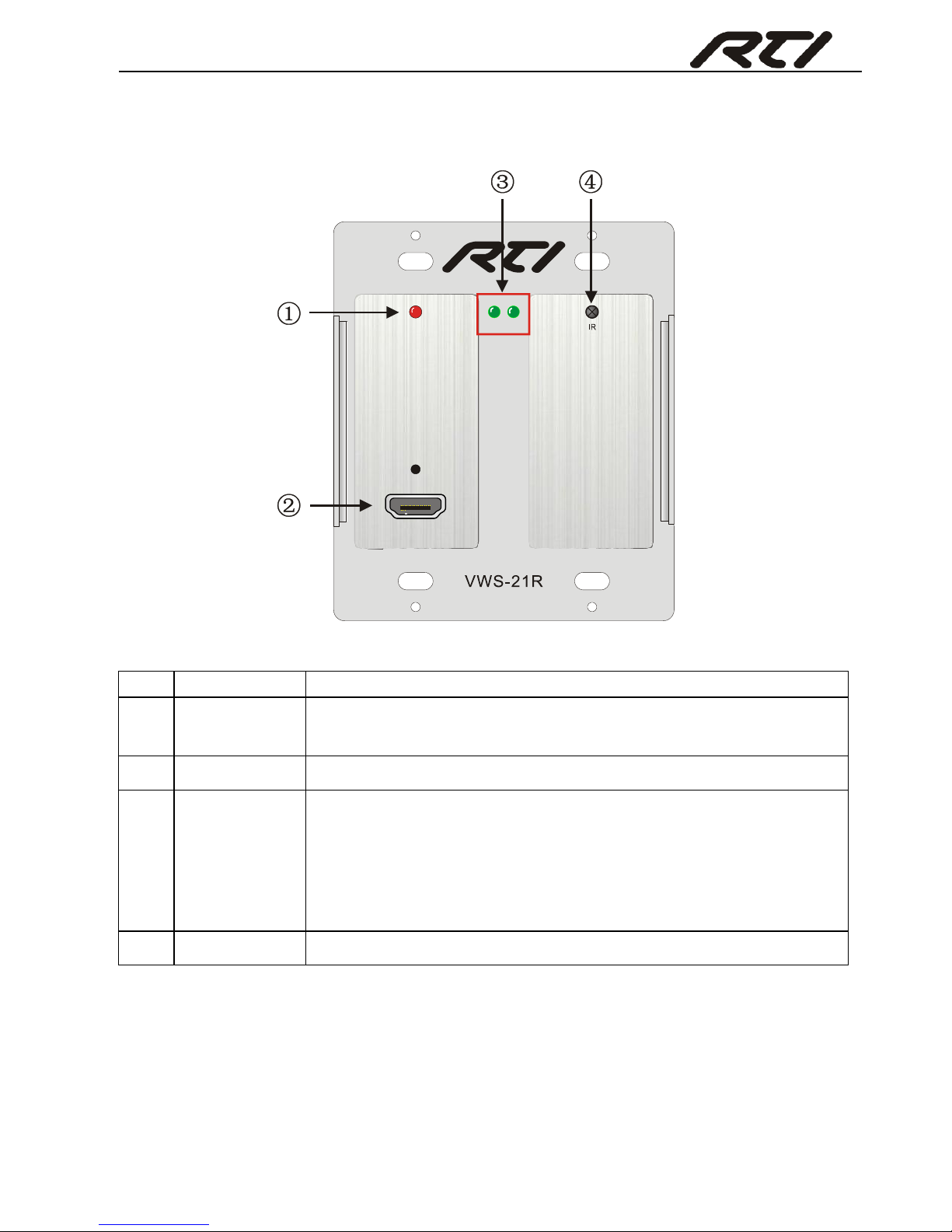
2.1 Front Panel
No.
Name
Description
①
Power
indicator
Illuminates red when powered on
②
HDMI OUT
Connect with HDMI display
③
LINK
&HDCP
LINK: Twisted Pair Link status indicator, illuminate green
when successfully connected.
HDCP: HDCP compliance indicator, illuminate green when
the source signals is with HDCP; blink when it is not with
HDCP; and turn off when there is no source signal.
④
IR
In-built IR sensor
LINK HDCPPOWER
HDMI OUT
Page 7
HDBaseT Wall Plate Receiver
3
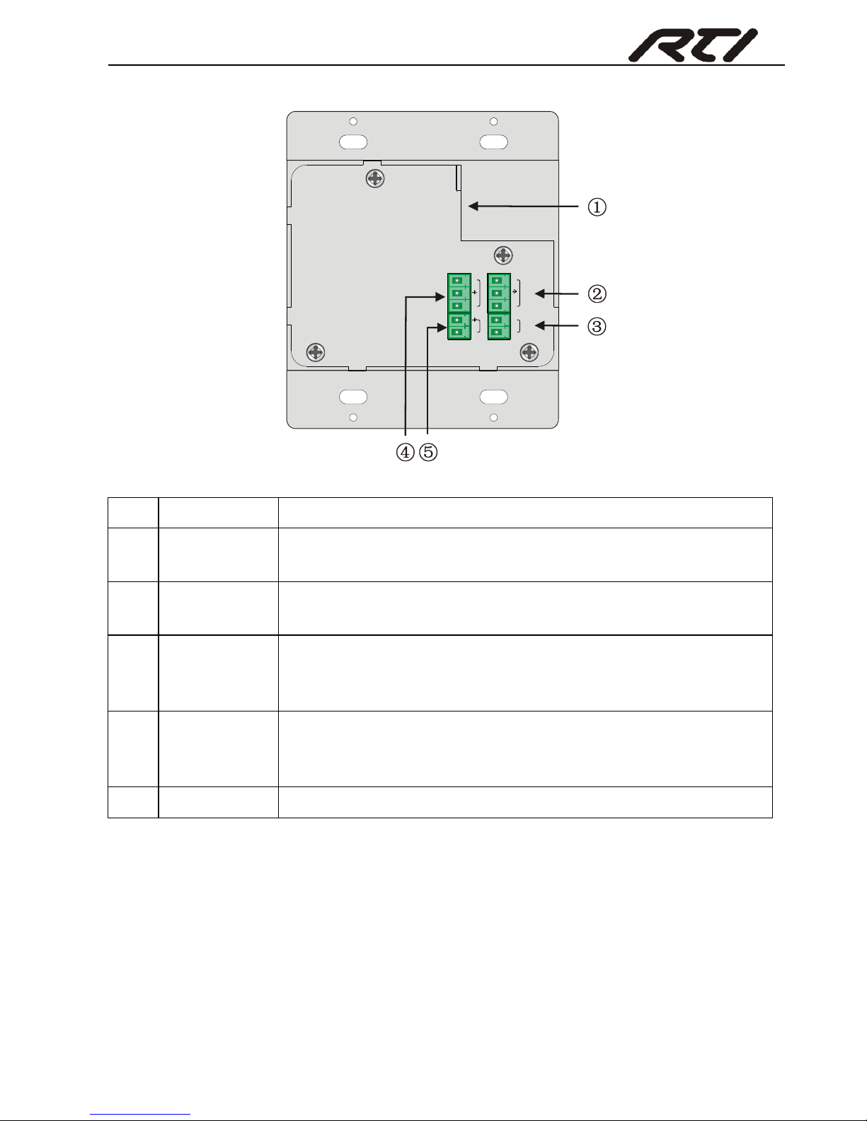
2.2 Rear Panel
No.
Name
Description
①
PoC IN&
HDBT IN
RJ45 port, connect with transmitter via a CAT5e/6 cable to
deliver AV& control signals, support PoC.
②
IR IN
Connect with IR receiver, receive IR signals sent from the IR
Emitter connected to the far-end receiver
③
IR OUT
Connect with IR Emitter, IR signals emitted from the IR emitter
are received by the IR receiver connected to the far-end
receiver.
④
RS232
Serial port, connects with a far-end receiver, supports
bi-directional RS232 control (send control signal from local or
receive control signal sent from far-end devices).
⑤
Power
Connect with DC 12V power adapter
Note:
VWS-21R can be energized via standard PoC& PoE, i.e. it can be energized by
far-end device.
Once connecting an IR Receiver to the IR IN socket, both the in-built IR sensor and
the extended IR Receiver is capable to collect IR signal.
Pictures shown in this manual are for reference only, different model and
specifications are subject to real product.
PoC IN
HDBT IN
RS232
12V
POWER
Tx
Rx
IR IN
SIG
IR OUT
SIG
5V
5V
Page 8

HDBaseT Wall Plate Receiver
4
3. System Connection
3.1 Usage Precautions
System should be installed in a clean environment and has a prop temperature
and humidity.
All of the power switches, plugs, sockets and power cords should be insulated and
safe.
All devices should be connected before power on.
3.2 System Diagram
The following diagram illustrates typical input and output connections that can be
utilized with VWS-21R (exampled by HDBaseT Twisted Pair PoC Transmitter):
Figure 3- 1 System connection
3.3 Connection Procedure
Step1. Connect HDMI source device (e.g. Blue-ray DVD) to HDMI IN socket of the
HDBaseT Twisted Pair PoC Transmitter with HDMI cable.
Step2. Connect the HDBT ports of HDBaseT Twisted Pair PoC Transmitter and
Page 9

HDBaseT Wall Plate Receiver
5
VWS-21R.
Step3. Connect a HDMI display to the HDMI OUT port of VWS-21R.
Step4. Connect a control terminal (e.g. a PC) to the RS232 port of either HDBaseT
Twisted Pair PoC Transmitter or VWS-21R.
Step5. Both HDBaseT Twisted Pair PoC Transmitter and VWS-21R have IR IN and IR
OUT sockets. When one model is used for IR signal receiver, the IR signal must
be sent out by the other model.
For example: When “IR IN” of VWS-21R connects with an IR receiver, the IR
emitter must connect to IR OUT of HDBaseT Twisted Pair PoC Transmitter.
Step6. Connect a DC 24V power adaptor to the power port of HDBaseT Twisted Pair
PoC Transmitter.
Note: IR& RS232 signal can be transmitted bi-directionally between VWS-21R and
HDBaseT Twisted Pair PoC Transmitter.
3.4 PoC/ PoE Solution
Apart from power supply, VWS-21R can be energized by far-end devices that support
PoC/ PoE, which increases the system flexibility.
Connect the receiver and far-end device (exampled by HDBaseT Twisted Pair PoC
Transmitter) via a CAT5e/6 cable as below:
Figure 3- 2 PoC Solution
AV and IR& RS232 control signal can also be transmitted via the cable.
3.5 Application
VWS-21R has a good application in various occasions, such as computer realm,
monitoring, conference room, big screen displaying, television education, command &
control center and smart home etc.
Page 10

HDBaseT Wall Plate Receiver
6
4. Specification
Note: All nominal levels are at ±10%.
Video
Input
1 HDBT
Output
1 HDMI
Input
Connector
1 RJ45
Output
Connector
1 19-pin Type A HDMI
female
Transmission
Distance
1080P≤20M
4Kx2K≤15M
Control Parts
Control Ports
1 RS232
2 IR IN (1 in-built IR sensor on front panel, 1 3.5mm IR IN on rear panel
1 IR OUT
General
Resolution
HDMI:4Kx2K, 1080P 3D, 1080P, 1080i, 720P, 576P, 576i, 480P, 480i
DVI:1920x1200@60Hz, 1920x1080@60Hz, 1600x1200@60Hz,
1280x1024@75Hz, 1280x1024@60Hz, 1024x768@75Hz,
1024x768@70Hz, 1024x768@60Hz, 800x600@75Hz,
800x600@72Hz, 800x600@60Hz, 640x480@75Hz, 640x480@72Hz,
640x480@60Hz
Transmission
Distance
1080P≤70M (PoC)
4Kx2K≤40M (PoC)
Bandwidth
10.2Gbps
HDMI
Standard
Support HDMI1.4 and HDCP
Chassis
Dimension
Decora style two gang
Power
Consumption
7w (Max)
Power
Supply
DC 12V 2A
Temperature
0 ~ 55℃
Reference
Humidity
10% ~ 90%
Dimension
(W*H*D)
89x 104 x 35 mm
Weight
0.24Kg
Page 11
HDBaseT Wall Plate Receiver
7
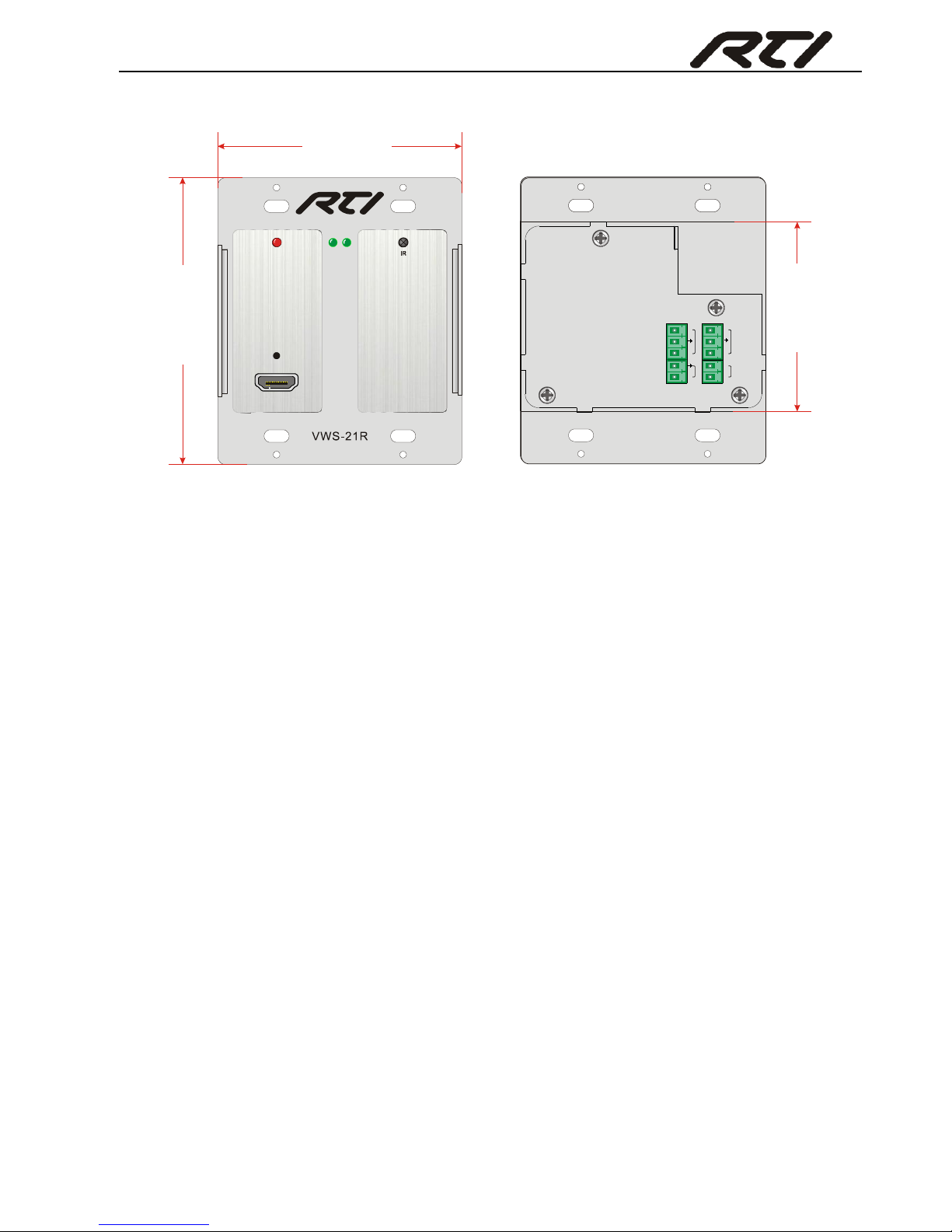
5. Panel Drawing
LINK HDCPPOWE R
HDMI O UT
89 mm
PoC IN
HDBT IN
RS23 2
12V
POWE R
Tx
Rx
IR IN
SIG
IR OUT
SIG
5V
5V
PoC IN
HDBT I N
RS23 2
12V
POWE R
Tx
Rx
IR IN
SIG
IR OUT
SIG
5V
5V
104 m
m
69 m
m
LINK HDCPPOWE R
HDMI O UT
Page 12
HDBaseT Wall Plate Receiver
8
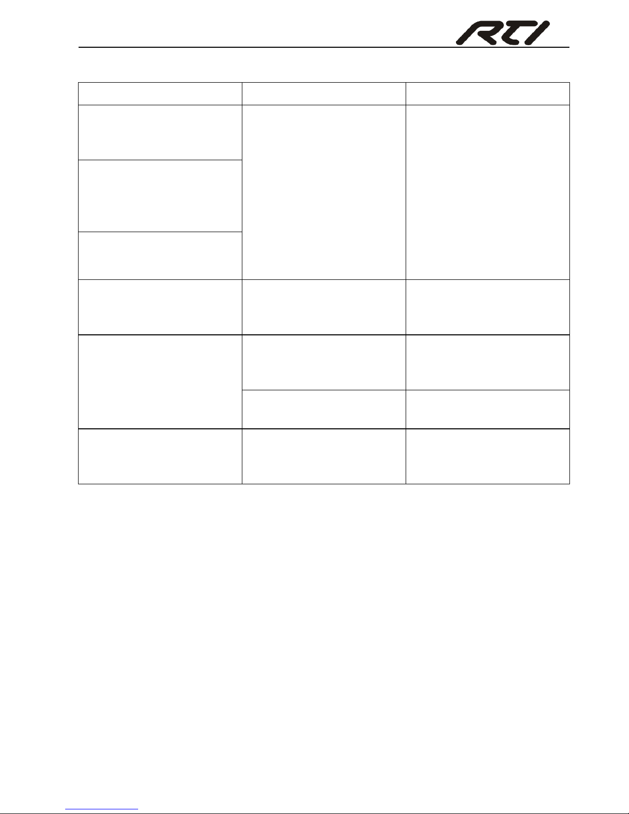
6. Troubleshooting & Maintenance
Problems
Potential Causes
Solutions
Color losing or no video
signal output in HDMI
display
The connecting cables may
not be connected correctly
or it may be broken
Check whether the cables
are connected correctly
and in working condition.
No HDMI signal output in
the device while local
HDMI input is in normal
working state
Output image with
snowflake
POWER indicator doesn’t
work or no respond to any
operation
Loose or failed power cord
connection
Ensure the power cord
connection is good
Cannot control the device
by control device (e.g. a
PC) through RS232 port
Wrong RS232
communication parameters
Make sure the RS232
communication parameters
are correct.
The unit is broken
Send it to authorized
dealer for repairing.
Static becomes stronger
when connecting the video
connectors
bad grounding
Check the grounding and
make sure it is connected
well.
If your problem persists after following the above troubleshooting steps, seek further
help from authorized dealer or our technical support.
Page 13

HDBaseT Wall Plate Receiver
9
7. Customer Service
The return of a product to our Customer Service implies the full agreement of the terms
and conditions hereinafter. There terms and conditions may be changed without prior
notice.
① Warranty
The limited warranty period of the product is fixed 3 (three) years.
② Scope
These terms and conditions of Customer Service apply to the customer service
provided for the products or any other items sold by authorized distributor only.
③ Warranty Exclusions:
Warranty expiration.
Factory applied serial number has been altered or removed from the product.
Damage, deterioration or malfunction caused by:
Normal wear and tear.
Use of supplies or parts not meeting our specifications.
No certificate or invoice as the proof of warranty.
The product model showed on the warranty card does not match with the
model of the product for repairing or had been altered.
Damage caused by force majeure.
Servicing not authorized by distributor.
Any other causes which does not relate to a product defect.
Shipping fees, installation or labor charges for installation or setup of the product.
④ Documentation:
Customer Service will accept defective product(s) in the scope of warranty coverage
at the sole condition that the defeat has been clearly defined, and upon reception of
the documents or copy of invoice, indicating the date of purchase, the type of
product, the serial number, and the name of distributor.
Remarks: For further assistance or solutions, please contact your local distributor.
Page 14

Page 15

Page 16

Remote Technologies Incorporated
5775 12th Avenue East, Suite 180
Shakopee, MN 55379
Tel: 952-253-3100
Fax: 952-253-3131
www.rticorp.com
 Loading...