

Page 1
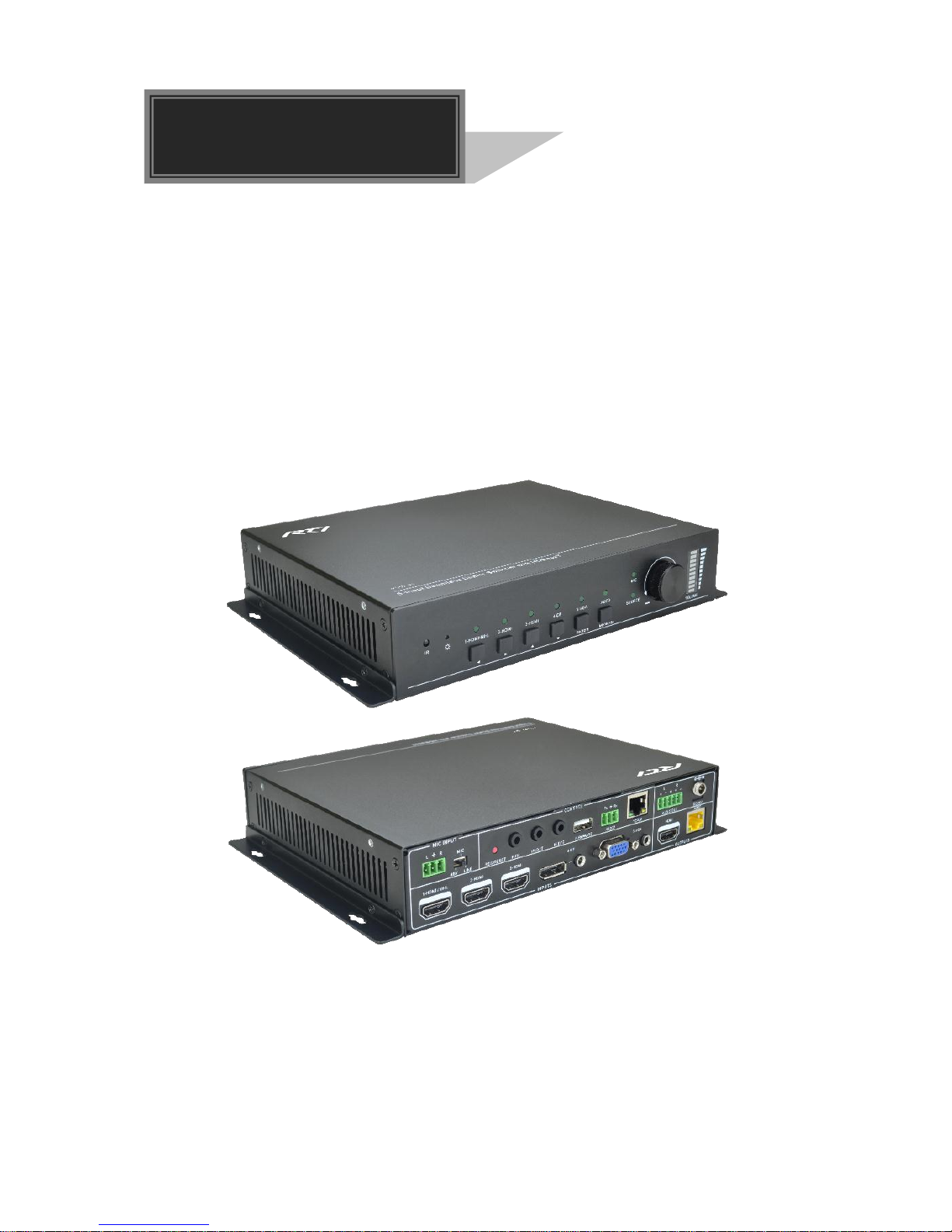
VSW-51
Compact Scaler Switcher Set
All Rights Reserved
Version: VSW-51_2017V1.0
User Manual
Page 2

Compact Scaler Switcher Set
Preface
Read this user manual carefully before using the product. Pictures shown in this manual
is for reference only, different model and specifications are subject to real product.
This manual is only for operation instruction only, not for any maintenance usage. The
functions described in this version are updated till November 3, 2017. In the constant
effort to improve our product, we reserve the right to make functions or parameters
changes without notice or obligation. Please refer to the dealers for the latest details.
Trademarks
Product model and logo are trademarks. Any other trademarks mentioned in this manual
are acknowledged as the properties of the trademark owner. No part of this publication
may be copied or reproduced without the prior written consent.
FCC Statement
This equipment generates, uses and can radiate radio frequency energy and, if not
installed and used in accordance with the instructions, may cause harmful interference
to radio communications. It has been tested and found to comply with the limits for a
Class B digital device, pursuant to part 15 of the FCC Rules. These limits are designed
to provide reasonable protection against harmful interference in a commercial
installation.
Operation of this equipment in a residential area is likely to cause interference, in which
case the user at their own expense will be required to take whatever measures may be
necessary to correct the interference.
Any changes or modifications not expressly approved by the manufacture would void
the user’s authority to operate the equipment.
Page 3

Compact Scaler Switcher Set
SAFETY PRECAUTIONS
To insure the best from the product, please read all instructions carefully before using
the device. Save this manual for further reference.
Unpack the equipment carefully and save the original box and packing material for
possible future shipment
Follow basic safety precautions to reduce the risk of fire, electrical shock and injury
to persons.
Do not dismantle the housing or modify the module. It may result in electrical shock
or burn.
Using supplies or parts not meeting the products’ specifications may cause damage,
deterioration or malfunction.
Refer all servicing to qualified service personnel.
To prevent fire or shock hazard, do not expose the unit to rain, moisture or install this
product near water.
Do not put any heavy items on the extension cable in case of extrusion.
Do not remove the housing of the device as opening or removing housing may
expose you to dangerous voltage or other hazards.
Install the device in a place with fine ventilation to avoid damage caused by
overheat.
Keep the module away from liquids.
Spillage into the housing may result in fire, electrical shock, or equipment damage. If
an object or liquid falls or spills on to the housing, unplug the module immediately.
Do not twist or pull by force ends of the optical cable. It can cause malfunction.
Do not use liquid or aerosol cleaners to clean this unit. Always unplug the power to
the device before cleaning.
Unplug the power cord when left unused for a long period of time.
Information on disposal for scrapped devices: do not burn or mix with general
household waste, please treat them as normal electrical wastes.
Page 4

Compact Scaler Switcher Set
Contents
1. Introduction ................................................................................................................. 1
1.1 Introduction to VSW-51 ...................................................................................... 1
1.2 Features ............................................................................................................ 1
1.3 Package List ...................................................................................................... 2
2. Panel Description ........................................................................................................ 3
2.1 Front Panel ................................................................................................ ........ 3
2.2 Rear Panel ......................................................................................................... 4
3. System Connection ................................ ................................ ................................ ..... 6
3.1 Usage Precautions ............................................................................................ 6
3.2 System Diagram ................................................................................................ 6
3.3 Connection Procedure ....................................................................................... 6
3.4 Connection of Microphone ................................................................................. 7
3.5 Application ......................................................................................................... 9
4. System Operations ................................................................................................... 10
4.1 Front Panel Buttons ......................................................................................... 10
4.1.1 Manual-Switching .................................................................................. 10
4.1.2 Auto-Switching ....................................................................................... 10
4.1.3 Volume Adjusting ................................................................................... 11
4.2 IR Control ........................................................................................................ 11
4.2.1 IR Remote ............................................................................................. 11
4.2.2 Control far-end device from local ........................................................... 12
4.2.3 Control local device from remote ........................................................... 12
4.2.4 CEC Function ........................................................................................ 13
4.3 RS232 Control ................................................................................................. 14
4.3.1 Installation/uninstallation of RS232 Control Software ............................ 14
4.3.2 Basic Settings ........................................................................................ 14
4.3.3 RS232 Communication Commands ...................................................... 16
4.3.4 Control Compact Scaler Switcher or 3rd Party Device from Local ......... 24
4.3.5 Control Compact Scaler Switcher or 3rd party device form Remote ...... 24
4.4 OSD Menu Control .......................................................................................... 25
4.4.1 OPTIONS .............................................................................................. 26
Page 5

Compact Scaler Switcher Set
4.4.2 PICTURE ............................................................................................... 27
4.4.3 SETUP .................................................................................................. 28
4.5 GUI Control ...................................................................................................... 29
4.5.1 Control Menu ......................................................................................... 30
4.5.2 Configuration Menu ............................................................................... 31
4.5.3 RS232 Control Menu ............................................................................. 33
4.5.4 Password Menu ..................................................................................... 34
4.5.5 GUI Update............................................................................................ 34
5. Specification ............................................................................................................. 35
6. Panel Drawing .......................................................................................................... 36
7. Troubleshooting & Maintenance ............................................................................... 37
8. Customer Service ..................................................................................................... 38
Page 6

Compact Scaler Switcher Set
1
1. Introduction
1.1 Introduction to VSW-51
The VSW-51 is a compact mini scaler switcher with 5 video inputs (1 HDMI/MHL, 2
HDMI, 1 DP, and 1 VGA) and 3 audio inputs (1 DP external audio, 1 VGA auxiliary audio,
1 MIC audio). The VGA input supports VGA, YPbPr and C-video, so the scaler switcher
is compliant with multiple video signals.
The Scaler Switcher scales & switches any video signal to HDMI output and HDBaseT
output (supports PoH and connects to an HDBaseT Receiver, up to a maximum
transmission distance of 70 meters.
With 1 IR IN, 1 IR OUT & 1 RS232, the IR & RS232 signals can be transmitted
bi-directionally between the Scaler Switcher and the HDBaseT Receiver.
In addition, The Scaler Switcher can be controlled via front panel buttons, IR remote,
RS232 commands and GUI.
1.2 Features
Compliant with HDMI1.4& HDCP2.2.
Supports CEC, with commands to enable/disable this function.
Supports video source auto-switching function.
Bi-directional IR & RS232 control.
Output resolutions selectable to assure preferred output, and supports various
output resolutions, such as 1920x1200, 1920x1080, 1600x1200, 1600x900,
1360x768, 1280x800, 1280x720, 1024x768.
VGA video supports C-video, YPbPr and VGA.
48V phantom power to support condenser microphone.
MIC port supports balance/unbalance signal, suppress the external noise
effectively.
3-level MIC input, supports condenser microphone, dynamic microphone and
wireless microphone.
Controllable via buttons, IR remote, RS232 & GUI.
Powerful OSD function.
Supports online software upgrading.
Page 7

Compact Scaler Switcher Set
2
1.3 Package List
Scaler
Switcher
1 x VSW-51 Compact Scaler Switcher
2 x Mounting Ears with 4 Screws
1 x Power Adapter (24VDC,2.71A)
4 x Plastic Cushions
1 x IR Remote
1 x VGA Converting Cable (VGA to YPbPr)
2 x 3-Pin Phoenix Connectors
1 x 5-Pin Phoenix Connector
1 x IR Emitter
1 x IR Receiver (with carrier wave)
Receiver
1 x VSW-51R HDBaseT Receiver
2 x Mounting Ears with 4 Screws
4 x Plastic Cushions
1 x RS232 Cable (3-Pin to DB9)
1 x User Manual
Note:Please confirm if the product and the accessories are all included, if not, please
contact with the dealers.
Page 8
Compact Scaler Switcher Set
3
2. Panel Description
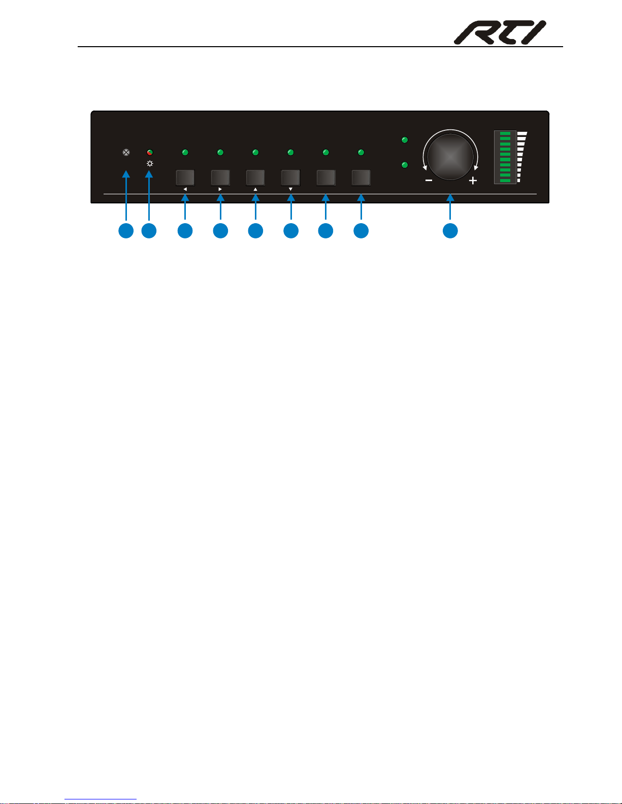
2.1 Front Panel
① Built-in IR Receiver
② Power indicator
Off when there is no power to the device
Red when the device is in standby mode
Green when the device is powered on
③ 1-HDMI/MHL input Selector & Activity LED; Left key
④ 2-HDMI input Selector & Activity LED; Right key
⑤ 3-HDMI input Selector & Activity LED; Up key
⑥ 4-DisplayPort input Selector & Activity LED; Down key
⑦ 5-VGA input Selector Activity LED; Enter key
⑧ Auto-Switching Mode Selector& Activity LED; OSD menu button
Press this button to enter or exit Auto-switching mode, in this mode, select input
source via front panel button is not available, but RS232 command and IR remote
are able to switch mode. The auto LED turn green and keep on.
Note: When you set any VGA port to C-video or YPbPr in Manual-switching
mode, the system will not be able to enter Auto-switching mode.
Long-press this button more than 2 seconds to enter OSD menu, and then use ③
~⑥direction keys, ⑦confirm key to control.
⑨ Volume Knob
Note: Pictures shown in this manual are for reference only, different model and
specifications are subject to real product.
SOURCE
MIC
VOLUME
IR 1-HDMI/MHL 5-VGA4-DP
3-HDMI
2-HDMI AUTO
ENTER MENU/2s
1
2
3
4
5
6
7
8 9
Page 9
Compact Scaler Switcher Set
4
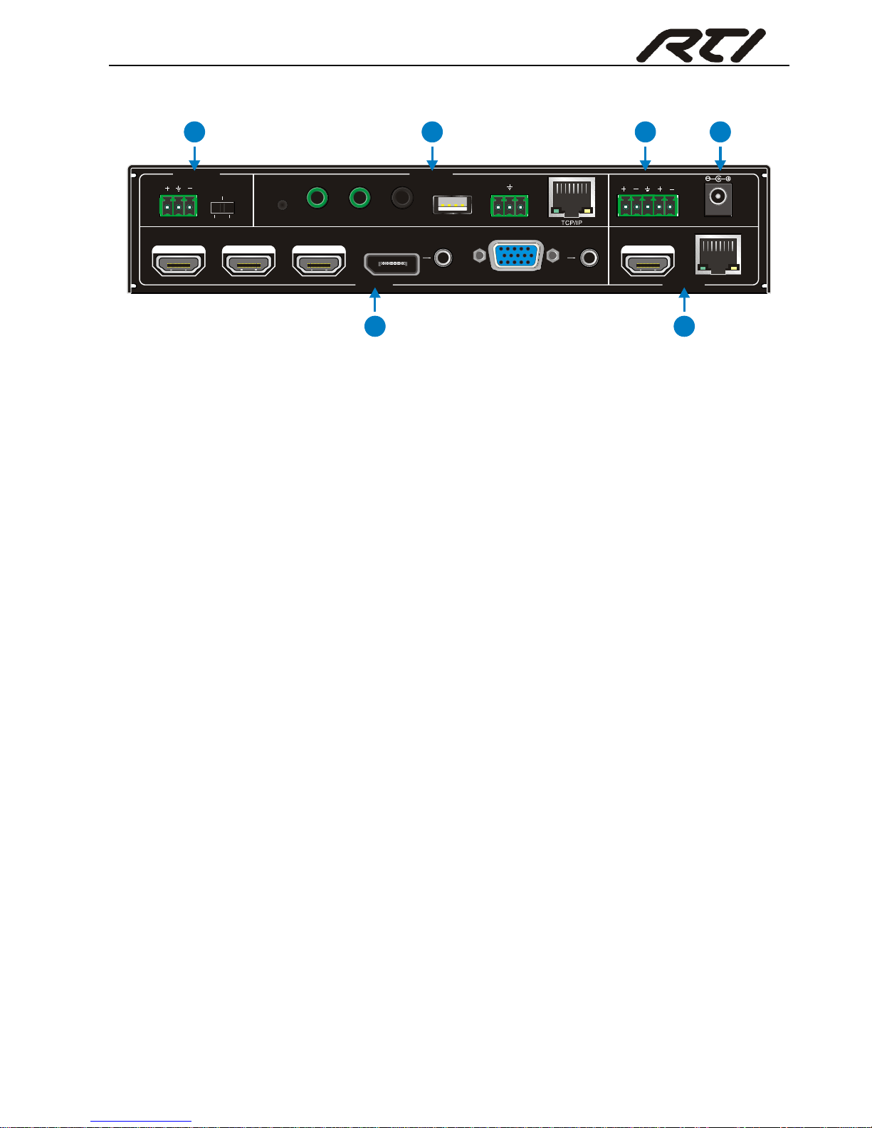
2.2 Rear Panel
① INPUTS
Video input ports: 1 HDMI/MHL input, 2 HDMI inputs, 1 DP and 1 VGA.
Audio input ports: 1 DP external audio input and 1 VGA auxiliary audio input.
② OUTPUTS
HDMI output: HDMI video output port
HDBaseT output: Support PoH. Connect with an HDBaseT Receiver to transmit
AV signal or IR/RS232 control signal.
HDBaseT output boasts green and yellow indicator. The green indicator will blink
when power. If connect an HDBaseT receiver to this output successfully, the yellow
indicator will light up, and the green indicator will keeps blinking.
③ MIC INPUT
MIC audio port: connect to Microphone.
Dial switch: including 3 level
48V phantom power mode (connect with condenser microphone);
MIC mode (connect with dynamic microphone);
LINE mode (connect with wireless microphone or line audio).
④ CONTROL
RES RESET: press this button to reset the output resolution to 1280×720p, or
activate HDMI and HDBT outputs when they are closed.
IR IN: connect with IR receiver (with carrier wave only) to receive IR signal to
control far-end device which was connected to HDBaseT Receiver via HDBaseT
output port.
IR OUT: connect with IR emitter to control local source devices from remote.
IR EYE: connect with IR receiver (with carrier wave only) to receive IR signal send
by IR remote to control this Scaler Switcher.
FIRMWARE: Type-A USB port for updating system firmware or loading
DC 24V 48V
LINE IR EYEIR IN IR OUT
MIC INPUT
MIC
FIRMWARE
AUDIO OUT
L R
RES RESET
RS232
Tx
Rx
INPUTS OUTPUTS
3-HDMI
2-HDMI1-HDMI / MHL 4-DP 5-VGA HDMI
HDBT
CONTROL
1
2
3
4
5
6
Page 10

Compact Scaler Switcher Set
5
customized EDID data.
RS232: Serial port, 3-pin phoenix connector, connect with a control device (such
as PC) to control the Scaler Switcher or other devices connected with HDBaseT
Receiver.
TCP/IP: Ethernet port, connect with PC to control the Scaler Switcher via GUI.
⑤ AUDIO OUTPUT
Audio output port, the audio comes from the input audio corresponding to the
selected video source and is mixed with MIC audio.
⑥ DC 24V
Power port, connect with DC 24V power adapter.
Note: Pictures shown in this manual are for reference only, different model and
specifications are subject to real product.
Page 11
Compact Scaler Switcher Set
6
3. System Connection
3.1 Usage Precautions
System should be installed in a clean environment and has a prop temperature
and humidity.
All of the power switches, plugs, sockets and power cords should be insulated and
safe.
All devices should be connected before power on.
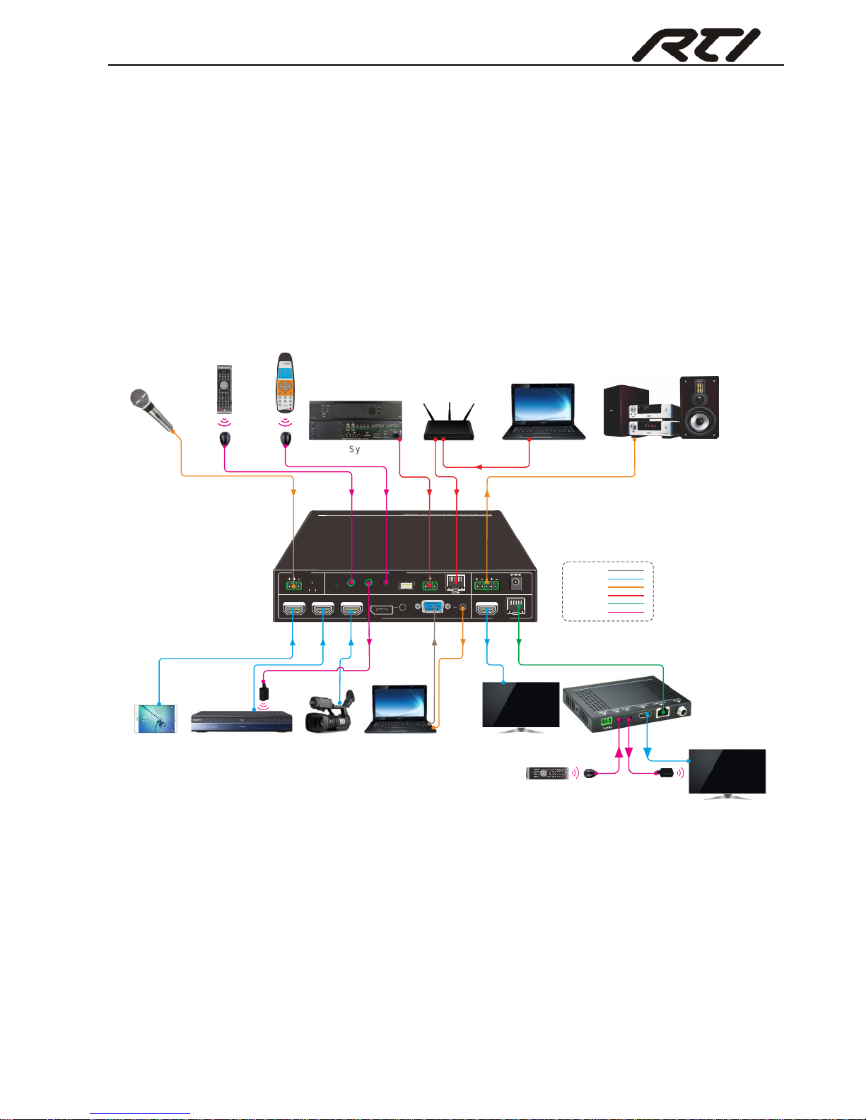
3.2 System Diagram
3.3 Connection Procedure
Step1. Connect HDMI source devices (e.g. Blue-ray DVD) to 1~3 HDMI input ports with
HDMI cable
Step2. Connect a DisplayPort source device (e.g. MAC MINI) to DP input port with
DisplayPort cable and DP audio input port with audio cable.
Step3. Connect a VGA source device (e.g. Laptop) to VGA input port with VGA cable
and VGA audio input port with audio cable.
DC 24V 48V LINE IR EYEIR IN I R OUT
MIC INPUT
MIC
FIRMWARE AUDIO OUT
L R
RES RESET
RS232
Tx
Rx
INPUTS OUTPU TS
3-HDMI2-HDMI1-HD MI / MHL 4-DP 5-VGA HDMI
HDBT
CONTRO L
IR Emitter
Camera
Laptop
TV Remote
Microphone
Speaker
Switcher Remote
Control System
Laptop
TV
HDBaseT Receiver
DVD Remote IR Receiver
DVD
TV
IR Emitter
VGA:
HDMI:
Audi o:
HDBa seT:
IR Control :
Control:
Pad
IR Receiver
Router
Page 12

Compact Scaler Switcher Set
7
Step4. Select MIC level and connect right microphone to MIC input port. MIC audio will
be transmitted to AUDIO OUTPUT port and mixed with source audio.
Step5. Connect a HDMI display device to HDMI output port with HDMI cable.
Step6. Connect HDBaseT Receiver to HDBT output port with twisted pair.
Step7. Connect speaker, headphone or AV amplifier to AUDIO OUTPUT port.
Step8. Connect control device (e.g. PC, control system) to the TCP/IP port, the Scaler
Switcher can be controlled via GUI.
Step9. Connect control device (e.g. PC) to the RS232 port of the Scaler Switcher or the
HDBaseT Receiver (bi-directional RS232 control, either end is available).
Step10. Connect IR receiver to the IR EYE port, the Scaler Switcher can be control via
IR remote. For more details, please refer to 4.2.IR Control.
Step11. Both the Scaler Switcher and the HDBaseT Receiver have IR IN and OUT.
When one model is connected with IR receiver, the other model should connect
with an IR transmitter.
For example: When “IR IN” of the Scaler Switcher connects with an IR receiver,
the IR transmitter must connect to IR OUT of HDBaseT Receiver.
The IR signal can be transmitted bi-directionally between the Scaler
Switcher and the HDBaseT Receiver.
Step12. Connect DC24V power adaptor to the power port (HDBaseT Receiver can be
powered by the Scaler Switcher with PoH function).
Note: If the power adapter is connecting with HDBaseT Receiver, the Scaler Switcher
can’t be powered from HDBaseT Receiver.
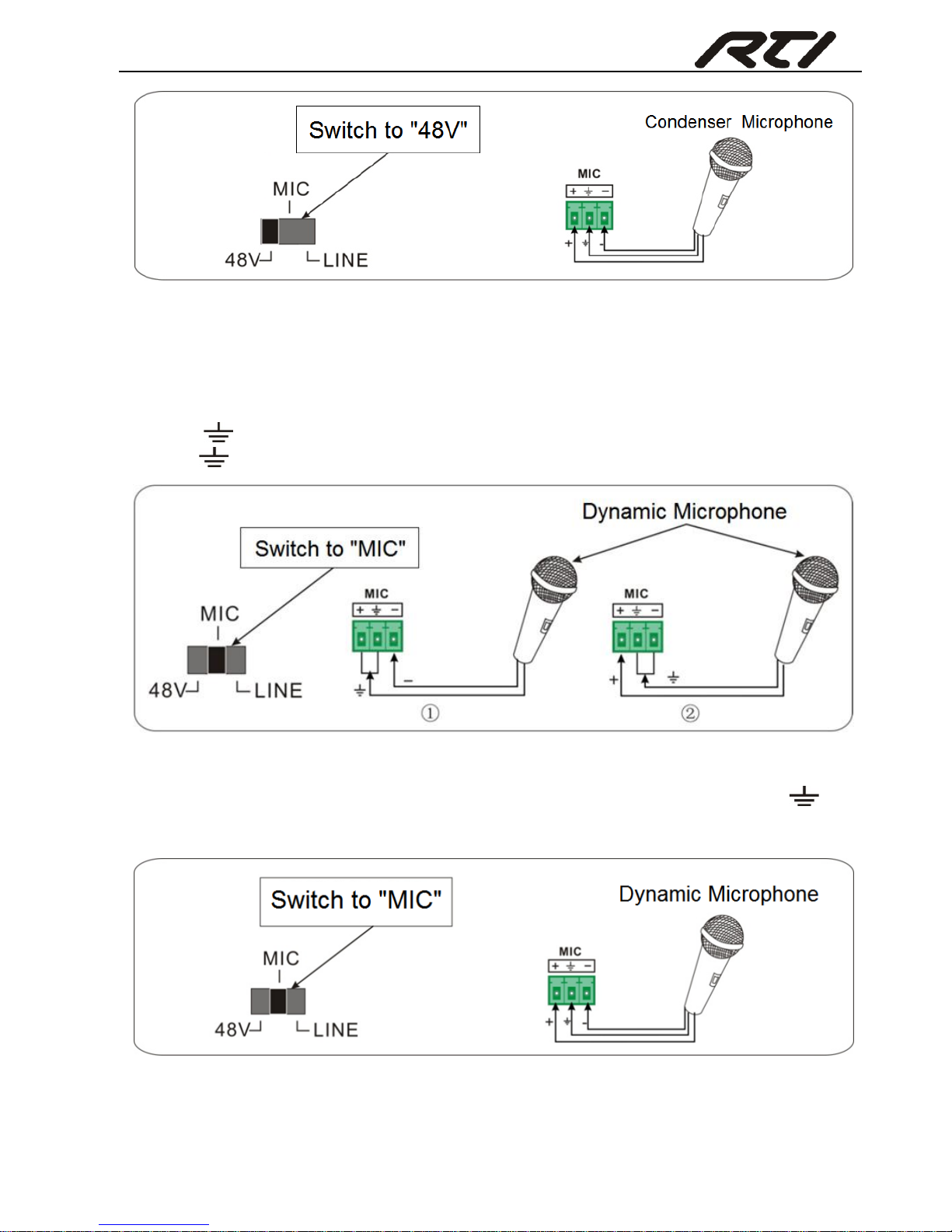
3.4 Connection of Microphone
The Scaler Switcher provides with one 3-level microphone input port, to accommodate
different microphone input modes, including 48V phantom power mode, MIC mode &
LINE mode.
48V phantom power Mode
48V phantom power input has a good frequency characteristic, high input impedance
and high sensitivity.
When switching to “48V”, the MIC input will provide a 48V phantom power. This is only
used for condenser microphone.
Connect the microphone in this way: “+” connects to positive, “-” connects to negative
and “ ” to ground.
Page 13
Compact Scaler Switcher Set
8
MIC Mode
MIC input has a low frequency characteristics, and wide frequency response.
When switch to “MIC”, the microphone input is used for connecting with dynamic
microphone. There are two different connection methods:
1) Unbalanced connection:
“+” and “ ” connect to ground, and “-” connects to signal.
“-” and “ ” connect to ground, and “+” connects to signal.
2) Balanced connection: “+” connects to positive, “-” connects to negative and “ ”
connects to ground.
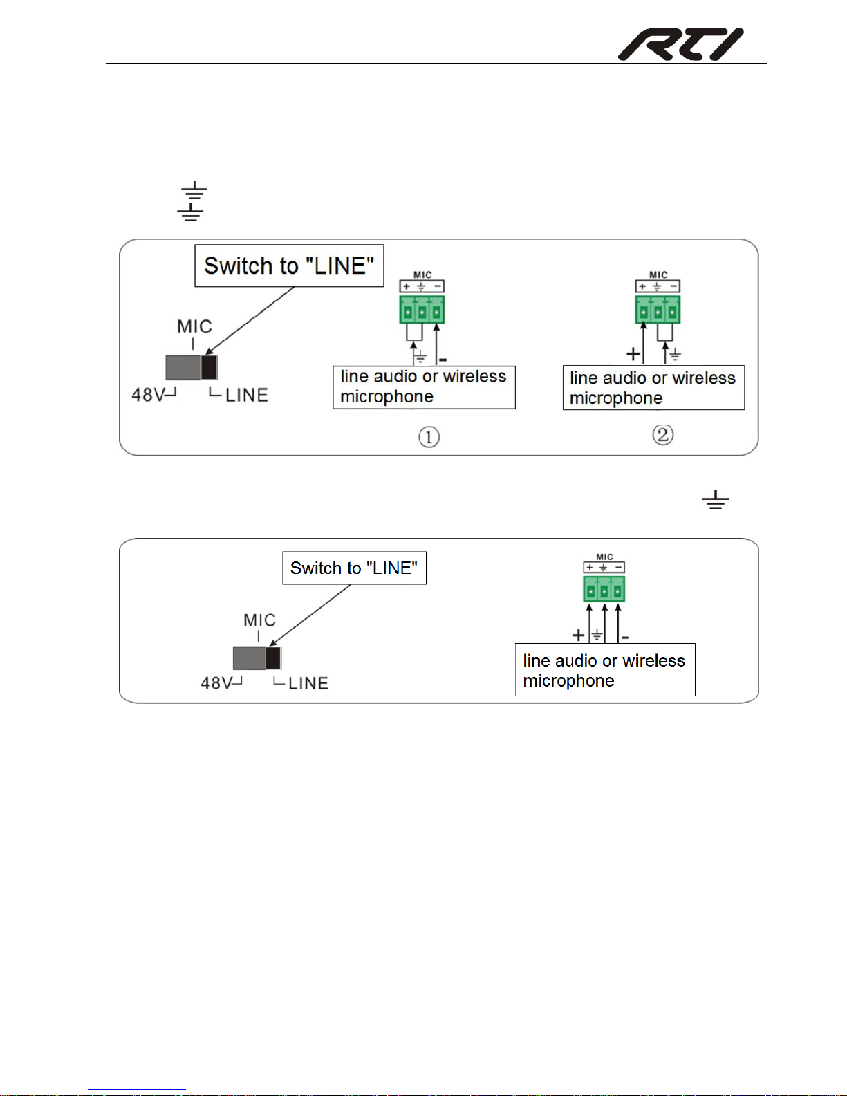
LINE Mode
LINE input has a low frequency characteristics, and wide frequency response.
Page 14
Compact Scaler Switcher Set
9
When switch to “LINE”, the microphone input is used for connecting with line audio or
wireless microphone output. There are two different connection methods:
1) Unbalanced connection:
“+” and “ ” connect to ground, and “-” connects to signal.
“-” and “ ” connect to ground, and “+” connects to signal.
2) Balanced connection: “+” connects to positive, “-” connects to negative and “ ”
connects to ground.
3.5 Application
The Scaler Switcher has a good application in various occasions, such as computer
realm, monitoring, conference room, big screen displaying, television education,
command & control center and smart home etc.
Page 15

Compact Scaler Switcher Set
10
4. System Operations
4.1 Front Panel Buttons
Front panel buttons can be used for switching operations and volume adjusting.
4.1.1 Manual-Switching
Press 1-HDMI/MHL, 2-HDMI, 3-HDMI, 4-DP, 5-VGA on front panel to select the
corresponding input source.
4.1.2 Auto-Switching
Press AUTO to enter in auto-switching mode.
The auto-switching mode abides by the following principles:
New input
Once detecting a new input signal, the switcher would switch to this new signal
automatically.
Rebooting device
The Scaler Switcher have the ability to save the last configuration before losing
power. If the last switching mode is auto-switching, once rebooted, the switcher will
automatically enter auto-switching mode, then detect all inputs and memorize their
connection status for future rebooting using. If the last displayed signal is still
available, the unit will output the signal. If not, the unit will detect all the input signals
wit priority from 1-HDMI/MHL to 5-VGA. When detected the first signal, it will transfer
to output.
Signal removing
Once removing the current display signal, the Scaler Switcher will detect all input
signals with priority from 1-HDMI/MHL to 5-VGA. It will transfer the signal firstly
detected to be available to output devices.
Note:
When the DP signal is switched as input, the DP source device may not read the
EDID data from display device, at this point re-plug the DP source device to solve
this phenomenon.
Auto-switching function works only when inputting new signal, removing a signal
or power rebooting. With any VGA port set to C-video or YPbPr, the system will be
not able to enter in Auto-switching mode.
Page 16

Compact Scaler Switcher Set
11
4.1.3 Volume Adjusting
Press Volume Knob to choose MIC/Source audio needed to be adjusted, the
corresponding LED will turn green and keep on.
Adjusting the Volume Knob in clockwise direction to increase sound volume.
Adjusting the Volume Knob in anti-clockwise direction to decrease sound volume.
4.2 IR Control
4.2.1 IR Remote
Connect IR receiver to IR EYE port, the Scaler Switcher cans be controlled by using IR
remote. As CEC function, it is able to use the IR remote to turn on/off the HDMI source
or Display.
① Enter/ exit standby mode
② Input channel selection buttons(1~5): Select
video source via pressing corresponding button
(audio switched following the corresponding
DP/VGA )
③ Auto button: Enter/Exit auto-switching mode.
④ Mute/ unmute audio
⑤ VOL: Volume adjusting button. After pressing
this button, the volume adjusting menu will be
showed on Display, and then press UP/DOWON
button to increase/decrease volume.
⑥ OK: confirm button; Navigation buttons:
UP/DWON/LEFT/ RIGHT button, for value setting
or page-turn.
⑦ Exit button: Exit OSD menu or current
operation.
⑧ Enter OSD menu or used to return to
previous menu.
OK
INPUT 1
INPUT 5
INPUT 2 INPUT 3
INPUT 4
Scaler Switcher
AUTO
MUTEVOL
2
3
4
7
6
8
1
5
Page 17

Compact Scaler Switcher Set
12
4.2.2 Control far-end device from local
Connect an IR receiver to IR IN port on the Scaler Switcher and connect IR emitter to
the IR OUT port on the HDBaseT Receiver, the far-end device can be control by its IR
remote from local.
4.2.3 Control local device from remote
Connect an IR emitter to IR OUT port on the Compact Scaler Switcher and connect IR
receiver to the IR IN port on the HDBaseT Receiver, the source devices can be control
by their IR remote from remote.
DVD
IR Remote
HDTV
48V
LINE IR EYEIR IN IR OUT
MIC INPUT
MIC
FIRM WARE
AUDIO OUT
L R
RES RESET
RS232
Tx
Rx
L R
INPUTS OUTPUTS
3-HDMI
2-HDMI1-HDMI / MHL 4-DP 5-VGA HDMI
HDBT
CONTROL
DC 24V
I
R O
U
T
I
R
IN
HDM
I O
U
T
HDBT IN
Tx Rx
HDBaseT Receiver
HDTV
Page 18

Compact Scaler Switcher Set
13
4.2.4 CEC Function
The Scaler Switcher supports CEC, it can be turned on/ off by sending RS232
commands or OSD menu operations. The default setting is ON.
Commands pertaining to CEC: “#CEC:ENABLE!” (Enable CEC) and “#CEC:DISABLE!”
(Disable CEC).
HDMI INPUT ports 1~3 support CEC, if the connected source devices also support CEC
and their CEC are on, users can control the source device and display via the IR remote
of the Scaler Switcher.
The working status related to CEC and STANDBY is showed as below:
Situation
Working Status
CEC: on, Standby: on
Press STANDBY button on IR remote, the Scaler Switcher
enters in standby mode, so do all HDMI source devices and
display.
Press STANDBY button again on IR remote, the Scaler
Switcher exits standby mode, the previous selected HDMI
input source device and display start working too.
CEC: on, Standby: off
Press STANDBY button on IR remote, the Scaler Switcher
enters in standby mode, HDMI 1~3 source devices and
display keep on.
CEC: on
Use , , , and buttons on IR
DVD
HDTV
48V
LINE IR EYEIR IN IR OUT
MIC INPUT
MIC
FIRMWARE
AUDIO OUT
L R
RES RESET
RS232
Tx
Rx
L R
INPUTS OUTPUTS
3-HDMI
2-HDMI1-HDMI / MHL
4-DP 5-VGA HDMI
HDBT
CONTROL
DC 24V
I
R
OU
T
I
R
IN
H
D
M
I O
U
T
HDBT IN
Tx Rx
HDBaseT Receiver
HDTV
IR Remote
Page 19

Compact Scaler Switcher Set
14
remote to control HDMI source device.
CEC: off
Unable to control HDMI source device and display through IR
remote
4.3 RS232 Control
As RS232 can be transmitted bi-directionally between the Scaler Switcher and the
HDBaseT Receiver, so it is able to control a third party RS232 device from local or
control the Scaler Switcher from remote. The baud rate support 2400, 4800,
9600(default), 19200, 38400, 57600 or 115200.
4.3.1 Installation/uninstallation of RS232 Control Software
Installation Copy the control software file to the computer connected with the Scaler
Switcher.
Uninstallation Delete all the control software files in corresponding file path.
4.3.2 Basic Settings
First to connect the Scaler Switcher with all input devices and output devices needed,
then to connect it with a computer which is installed with RS232 control software.
Double-click the software icon to run this software.
Here we take the software CommWatch.exe as example. The icon is showed as below:
48V LIN E IR EYEIR IN IR OUT
MIC INPUT
MIC
FIRM WARE AUDIO O UT
L R
RES RE SET
RS23 2
Tx
Rx
L R
INPUTS OUTPUTS
3-HD MI2-HD MI1-HDMI / MHL 4-DP 5-VGA HDMI
HDBT
CONTROL
DC 24V
DVD(Signal Source)
O
K
Z
O
O
M
S
.
M
M
E
N
U
E
X
I
T
I
N
P
U
T
1
P
.
M
1
0
8
0
P
7
2
0
P
M
E
N
U
I
N
P
U
T
5
I
N
P
U
T
2
I
N
P
U
T
3
I
N
P
U
T
4
A
U
T
O
S
c
a
l
e
r
S
w
i
t
c
h
e
r
A
U
T
O
P
L
A
Y
/
P
A
U
S
E
S
T
O
P
R
E
V
F
W
D
I
N
P
U
T
S
O
U
R
C
E
C
E
C
C
O
N
T
R
O
L
M
I
C
M
U
T
E
M
I
C
L
I
N
E
L
I
N
E
M
U
T
E
DVD(Signal Source) DVD(Signal Source)
HDTV
Page 20

Compact Scaler Switcher Set
15
The interface of the control software is showed as below:
Please set the parameters of COM number, bound rate, data bit, stop bit and the parity
bit correctly, and then you are able to send command in Command Sending Area.
Parameter Configuration area
Monitoring area, indicates if the
command sent works.
Command Sending area
Page 21

Compact Scaler Switcher Set
16
4.3.3 RS232 Communication Commands
Communication protocol: RS232 Communication Protocol
Baud rate: 9600 Data bit: 8 Stop bit: 1 Parity bit: none
Command
Function
Feedback Example
System Commands
#MOD?!
Report system model.
@MOD:VSW-51!
#IPA?!
Report IP address of device.
@IPA:192.168.0.100!
#RST!
Factory reset.
@RST:OK!
#POW?!
Report power status and Auto Off time.
@POW:ON!
@OUT:AUTO OFF 00!
@OUT:AUTO OFF 01!
@OUT:AUTO OFF 02!
@OUT:AUTO OFF 05!
@OUT:AUTO OFF 10!
#POW:ON!
Power on the system.
@POW:ON!
#POW:OFF!
Power off the system.
@POW:OFF!
#FPL?!
Report front panel lock status.
@FPL:LOCKED!
@FPL:UNLOCKED!
#FPL:LOCK!
Lock front panel button.
@FPL:LOCKED!
#FPL:UNLOCK!
Unlock front panel button (Default).
@FPL:UNLOCKED!
#FWV?!
Report firmware version.
@FWV:1.2.3!
#HWV?!
Report hardware version.
@HWV:4.5.6!
#FBK:OFF!
Disable feedback message.
@FBK:OFF!
#FBK:ON!
Enable feedback message (Default).
@FBK: ON!
#RPT:STATUS?!
Display status including MIC, Source
audio, Resolution, Manual/
Auto-switching modes, VGA audio mute
on/off, DP audio status.
@VOL:SRC 30!
@VOL:MIC 20!
@RAV:VIDEO 03 TO
OUT 01!
@RAV:AUDIO 03 TO
OUT 01!
Page 22

Compact Scaler Switcher Set
17
Command
Function
Feedback Example
@RES:OUT 01
1920x1080P60!
@CFG:AUTOSWITCH
ON!
@VOL:SRC MUTE!
@VOL:MIC MUTE!
@VOL:VGA MUTE!
@VOL:DPA MUTE!
@CFG:DPA EMB!
#CFG:FWUPDAT
E!
Firmware update
@CFG:UPDATE FW!
Signal Switching
#RAV:[XX]AV01!
Switch Input [XX] AV signal to output
01. [XX] = 01 - HDMI1;02 - HDMI2; 03 HDMI3; 04 - DisplayPort; 05 – VGA
@RAV:VIDEO 03 TO
OUT 01!
@RAV:AUDIO 03 TO
OUT 01!"
#RPT:01?!
Report the input channel on output 01.
@RAV:VIDEO 03 TO
OUT 01!
@RAV:AUDIO 03 TO
OUT 01!"
#CFG:INP05VGA
!
Set the signal format to VGA for 5-VGA
input.
@CFG:INP 05 VGA!
#CFG:INP05YPB
PR!
Set the signal format to YPbPr for
5-VGA input.
@CFG:INP 05 YPBPR!
#CFG:INP05YCVI
DEO!
Set the signal format to AV(C-video) for
5-VGA input.
@CFG:INP 05
YCVIDEO!
#CFG:INP05TYP
E?!
Report signal format of VGA input.
@CFG:INP 05 VGA!
@CFG:INP 05 YPBPR!
@CFG:INP 05
YCVIDEO!
#CFG:VGAAUTO
ADJ!
Auto adjust of VGA.
@CFG:VGA AUTO
ADJUST!
#CFG:AUTOSWI
Enable auto-switching.
@CFG:AUTOSWITCH
Page 23

Compact Scaler Switcher Set
18
Command
Function
Feedback Example
TCHON!
ON!
#CFG:AUTOSWI
TCHOFF!
Disable auto-switching.
@CFG:AUTOSWITCH
OFF!
#CFG:AUTOSWI
TCH?!
Report auto switching.
@CFG:AUTOSWITCH
ON!
@CFG:AUTOSWITCH
OFF!
Audio Setting
#VOL:SRCMUTE!
Mute Source Audio.
@VOL:SRC MUTE!
#VOL:SRCUNMU
TE!
Unmute Source Audio.
@VOL:SRC UNMUTE!
#VOL:SRCMUTE
?!
Inquiry Mute Source Audio.
@VOL:SRC MUTE!
@VOL:SRC UNMUTE!
#VOL:SRCUP!
Volume Up for Source Audio.
XX=00~60.
@VOL:SRC XX!
#VOL:SRCDN!
Volume Down for Source Audio.
XX=00~60.
@VOL:SRC XX!
#VOL:SRC[XX]!
Set Volume to [XX] for Source Audio.
XX=00~60.
@VOL:SRC XX!
#VOL:MICMUTE!
Mute MIC Audio.
@VOL:MIC MUTE!
#VOL:MICUNMU
TE!
Unmute MIC Audio.
@VOL:MIC UNMUTE!
#VOL:MICMUTE?
!
Inquiry Mute MIC Audio.
@VOL:MIC MUTE!
#VOL:MICUP!
Volume Up for MIC Audio. XX=00~60.
@VOL:MIC XX!
#VOL:MICDN!
Volume Down for MIC Audio.
XX=00~60.
@VOL:MIC XX!
#VOL:MIC[XX]!
Set Volume to [XX] for MIC Audio.
XX=00~60.
@VOL:MIC XX!
#VOL?!
Inquiry volume.
@VOL:SRC 30!
@VOL:MIC 20!"
#VOL:VGAMUTE
Mute VGA Audio.
@VOL:VGA MUTE!
Page 24

Compact Scaler Switcher Set
19
Command
Function
Feedback Example
!
#VOL:VGAUNMU
TE!
Unmute VGA Audio.
@VOL:VGA UNMUTE!
#VOL:VGAMUTE
?!
Inquiry Mute VGA Audio.
@VOL:VGA MUTE!
@VOL:VGA UNMUTE!
#VOL:DPAMUTE!
Mute DP Audio.
@VOL:DPA MUTE!
#VOL:DPAUNMU
TE!
Unmute DP Audio.
@VOL:DPA UNMUTE!
#VOL:DPAMUTE
?!
Inquiry Mute DP Audio.
@VOL:DPA UNMUTE!
@VOL:DPA UNMUTE!
#CFG:DPAEMB!
Select embedded audio as audio input
for DP video signal.
@CFG:DPA EMB!
#CFG:IDPAOEXT
!
Select external audio as audio input for
DP video signal.
@CFG:DPA EXT!
#CFG:DPA?!
Inquiry DP audio status.
@CFG:DPA EMB!
@CFG:DPA EXT!
Output Resolution Selection
#CFG:OUT01RE
SHD!
Set the output resolution to 1360X768
HD.
@CFG:OUT 01
RESHD!
#CFG:OUT01RE
SXGA!
Set the output resolution to 1024X768
XGA.
@CFG:OUT 01
RESXGA!
#CFG:OUT01RE
S720P!
Set the output resolution to 1280X720
720P.
@CFG:OUT 01
RES720P!
#CFG:OUT01RE
SWXGA!
Set the output resolution to 1280X800
WXGA.
@CFG:OUT 01
RESWXGA!
#CFG:OUT01RE
S1080P!
Set the output resolution to 1920X1080
1080P.
@CFG:OUT 01
RES1080P!
#CFG:OUT01RE
SWUXGA!
Set the output resolution to1920X1200
WUXGA.
@CFG:OUT 01
RESWUXGA!
#CFG:OUT01RE
SUXGA!
Set the output resolution to1600X1200
UXGA.
@CFG:OUT 01
RESUXGA!
#CFG:OUT01RE
SHD+!
Set the output resolution to 1600X900.
@CFG:OUT 01
RESHD+!
Page 25

Compact Scaler Switcher Set
20
Command
Function
Feedback Example
#RES:OUT?!
Inquiry output resolution.
@RES:OUT 01
1920x1080P60!
0000x0000P00 = no
input/output
#IMG:FRZON!
Freeze output image.
@IMG:FRZ ON!
#IMG:FRZ?!
Inquiry freeze status.
@IMG:FRZ ON!
@IMG:FRZ OFF!
#MIC:
NOSIEDETECTO
N!
Enable MIC noise detecting.
@MIC: NOSIEDETECT
ON!
#MIC:
NOSIEDETECTO
FF!
Disable MIC noise detecting.
@MIC: NOSIEDETECT
OFF!
#MIC:
NOSIEDETECT?!
Check MIC noise detecting status.
@MIC: NOSIEDETECT
ON!
@MIC: NOSIEDETECT
OFF!
HDCP Management
#HDP:ACTIVE!
HDCP active mode.
@HDP:ACTIVE!
#HDP:MANUAL!
HDCP manual mode.
@HDP:MANUAL!
#HDP:OUT01ON!
Enable HDCP output.
@HDP:OUT 01 ON!
#HDP:OUT01OFF
!
Disable HDCP output.
@HDP:OUT 01 OFF!
#HDP?!
Inquiry HDCP.
@HDP:ACTIVE!"
EDID Management
#EDD:INITIAL!
Restore default EDID.
@EDD:INITIAL!
#EDD:BYPASS!
Bypass EDID data from output to input.
@EDD:BYPASS!
#EDD:CUSTOM!
Upload custom EDID data to the
switcher.
@EDD:CUSTOM!
#EDD?!
Inquire EDID status.
@EDD:CUSTOM!
@EDD:BYPASS!
@EDD:INITIAL!
Page 26

Compact Scaler Switcher Set
21
Command
Function
Feedback Example
#EDD:MANAGE!
EDID management, copy the best
resolution data of one output to HDMI
input.
@CFG:OUT 01
RES1080P!
@EDID:MANAGE
1920x1080P60!
Serial Control Mode
#CFG:OUT01RS2
32M1!
Enable serial control mode 1: control
Scaler & far-end from local RS232.
@CFG:OUT 01 RS232
M1!
#CFG:OUT01RS2
32M2!
Enable serial control mode 2: control
Scaler from local RS232 and far-end).
@CFG:OUT 01 RS232
M2!
OSD Control
#OSD:MENU!
MENU button (enter OSD).
@OSD:MENU!
#OSD:EXIT!
EXIT button (exit OSD).
@OSD:EXIT!
#OSD:OK!
OK for OSD selection.
@OSD:OK!
#OSD:UP!
UP button.
@OSD:UP!
#OSD:DN!
DOWN button.
@OSD:DN!
#OSD:LT!
LEFT button.
@OSD:LT!
#OSD:RT!
RIGHT button.
@OSD:RT!
Screen Output Adjusting
#ADJ:ENABLE!
Enable screen output adjusting.
@ADJ:ENABLED!
#ADJ:DISABLE!
Disable screen output adjusting.
@ADJ:DISABLED!
#ADJ:POSLT!
Move the image to left.
@ADJ:POS LEFT!
#ADJ:POSRT!
Move the image to right.
@ADJ:POS RIGHT!
#ADJ:POSUP!
Move the image up.
@ADJ:POS UP!
#ADJ:POSDN!
Move the image down.
@ADJ:POS DOWN!
#ADJ:WDTPLUS!
Stretch left from left side (increase
image width).
@ADJ:WDT PLUS!
#ADJ:WDTMINU
S!
Pull right from left side (decrease image
width).
@ADJ:WDT MINUS!
#ADJ:HGTMINUS
!
Stretch upwards from bottom side
(decrease image height).
@ADJ:HGT MINUS!
#ADJ:HGTPLUS!
Stretch downwards from bottom side
(increase image height).
@ADJ:HGT PLUS!
Page 27

Compact Scaler Switcher Set
22
Command
Function
Feedback Example
HDMI & HDBT Output Setting
#OUT:HDMION!
Turn on HDMI output.
@OUT:HDMI ON!
#OUT:HDMIOFF!
Turn off HDMI output.
@OUT:HDMI OFF!
#OUT:HDBTON!
Turn on HDBT output.
@OUT:HDBT ON!
#OUT:HDBTOFF!
Turn off HDBT output.
@OUT:HDBT OFF!
#OUT:BOTHON!
Turn on HDMI& HDBT output
synchronously.
@OUT:HDMI ON!
@OUT:HDBT ON!"
#OUT:BOTHOFF!
Turn off HDMI& HDBT output
synchronously.
@OUT:HDMI OFF!
@OUT:HDBT OFF!"
#OUT:BOTH?!
Inquiry HDMI and HDBT output status.
@OUT:HDMI OFF!
@OUT:HDBT OFF!"
#OUT:AUTOOFF[
XX]!
No input for [XX] minutes to turn off
output.
[XX] = 01,02,05,10 minutes; 00 is
disable.
@OUT:AUTO OFF 10!
CEC Commands
#CEC:ENABLE!
Enable CEC.
@CEC:ENABLED!
#CEC:DISABLE!
Disable CEC.
@CEC:DISABLED!
#CEC?!
Inquiry CEC.
@CEC:ENABLED!
@CEC:DISABLED!
#CEC:PLAY!
Play & pause.
@CEC:PLAY!
#CEC:STOP!
Stop.
@CEC:STOP!
#CEC:MENU!
Menu.
@CEC:MENU!
#CEC:REV!
Retreat.
@CEC:REV!
#CEC:FF!
Forward.
@CEC:FF!
#CEC:UP!
Up.
@CEC:UP!
#CEC:DN!
Down.
@CEC:DN!
#CEC:LT!
Left.
@CEC:LT!
#CEC:RT!
Right.
@CEC:RT!
#CEC:CONFIRM!
Confirm command.
@CEC:CONFIRM!
Page 28

Compact Scaler Switcher Set
23
Command
Function
Feedback Example
#CEC:EXIT!
Exit command.
@CEC:EXIT!
#CEC:SOURCEO
N!
Source power on.
@CEC:SOURCE ON!
#CEC:SOURCEO
FF!
Source power off.
@CEC:SOURCE OFF!
#CEC:DISPLAYO
N!
Display power on.
@CEC:DISPLAY ON!
#CEC:DISPLAYO
FF!
Display power off.
@CEC:DISPLAY OFF!
Note:
Screen output adjusting avails only when the screen output adjusting is on. Send
command “#ADJ:ENABLE!” to turn on.
Under HDCP ON or HDCP OFF mode, the video signal can be switched to HDMI
and HDBaseT output seamlessly, while sending “#HDP:ACTIVE!” to set as HDCP
Active mode, the video signal can’t support seamless switching.
All input and output number MUST be in 2 Digits (e.g. Input channel 1 must be
wrote as 01)
Page 29

Compact Scaler Switcher Set
24
4.3.4 Control Compact Scaler Switcher or 3rd Party Device from Local
Firstly, according the following connection diagram to connect all devices as needed.
Secondly, send command “#CFG:OUT01RS232M1!”(serial control mode 1, factory
default) via RS232 communication software.
Lastly, send the right command of the Scaler Switcher or other remote RS232 device
connected in present system. Connect as below:
Control Compact Scaler Switcher or 3rd party device from local
4.3.5 Control Compact Scaler Switcher or 3rd party device form Remote
Firstly, according the following connection diagram to connect all devices as needed.
Secondly, send command “#CFG:OUT01RS232M2!” via RS232 communication
software.
Lastly, send the right command to control the Scaler Switcher. Connect as below:
3rd party
PC
48V LINE IR EYEIR IN
IR OUT
MIC INPUT
MIC
FIRMWARE AUDIO OUT
L R
RES RESET
RS232
Tx
Rx
L R
INPUTS OUTPUTS
3-HDMI
2-HDMI1-HDMI / MHL 4-DP 5-VGA HDMI
HDBT
CONTROL
DC 24V
I
R
OU
T
IR
I
N
H
DMI
OU
T
HDBT IN
Tx Rx
HDBaseT Receiver
Page 30

Compact Scaler Switcher Set
25
Control Compact Scaler Switcher or 3rd party device from Remote
4.4 OSD Menu Control
The Scaler Switcher provides a powerful OSD operation menu, contains 3 parts:
optional settings, image settings, and system setting etc.
There are three ways to enter OSD menu:
Long-press the button MENU/2s on front panel 2 seconds or more.
Press MENU button on IR remote.
Send the command “#OSD:MENU!” on RS232 Control Software.
Operation way:
Press direction buttons on front panel or IR remote to switch between menu options
and menu pages.
Press ENTER on front panel or OK on the IR remote to confirm the selection.
PC
48V LINE IR EYEIR IN IR OUT
MIC INPUT
MIC
FIRMWARE AUDIO OUT
L R
RES RESET
RS232
Tx
Rx
L R
INPUTS OUTPUTS
3-HDMI
2-HDMI1-HDMI / MHL 4-DP 5-VGA HDMI
HDBT
CONTROL
DC 24V
I
R
OU
T
I
R
IN
H
D
M
I O
U
T
HDBT IN
Tx Rx
HDBaseT Receiver
3rd party
Page 31

Compact Scaler Switcher Set
26
4.4.1 OPTIONS
Includes Output Adjust, Input 5 Select, Baud rate, User EDID Load (USB), Resolution,
and Software Update (USB).
Output Adjust: Adjust output image position (X: horizontal direction and Y: vertical
direction), ratio aspect (width and height), polarity adjustment (H Polarity and V
Polarity) and output setting (HDMI on/off and HDBT on/off).
Input5 Select: Select video source format for VGA input, includes AV 1 (C-video
signal), VGA 1 (VGA signal) and YPbPr 1 (Component video signal).
Baud rate: Set the baud rate for RS232 control, and it support 2400、4800、9600、
19200、38400、57600、115200.
User EDID Load (USB): Insert the USB flash disk with EDID file to FIRMWARE port
to load EDID data through this menu.
Resolution: Set the output resolutions, and it support 1920x1200, 1920x1080,
1600x1200, 1600x900, 1360x768, 1280x800, 1280x720, 1024x768.
Pw Off Time (Auto): Set the auto power off time when no signal input (1, 2, 5 or 10
minutes can be chosen).
Pw Off Time (Manual): Set the power off time when no signal input (1, 2, 5 or 10
minutes can be chosen).
IP: Show the IP address.
Software Update (USB): Insert the USB flash disk with updating file to USB port of
the Scaler Switcher, to update the software through this menu.
Page 32

Compact Scaler Switcher Set
27
4.4.2 PICTURE
Including Picture Mode, Color Temperature, Aspect Ratio, Noise Reduction, Screen and
Color Range.
Please check the picture below:
Picture mode: Include Dynamic, Standard, Mild, and User. Only in User mode, will
it be able to set the image contrast, brightness, color and sharpness.
Color Temperature: Include Cool, Medium, Warm and User. And only in User mode,
it is able to set values for Red, Green and Blue (RGB).
Aspect Ratio: Include Native, 4:3, 16:9, Zoom1, Zoom2, Just Scan, and Panorama.
VGA format only supports 4:3, 16:9 and Panorama.
Noise Reduction (not for VGA format): Includes Off, Low, Middle, High and Default.
Screen: (not for HDMI source): Include Auto Adjust, Horizontal, Vertical, Size, and
Phase.
Page 33

Compact Scaler Switcher Set
28
4.4.3 SETUP
Including OSD Language, Restore Factory Default, Blending, HDMI CEC, OSD
Duration and version inquiry
OSD Language: Supports 7 languages, including English (default), Chinese etc.
Restore Factory Default: Restores to original system state
Blending: Includes Low, Middle, High and Off.
HDMI CEC: Enable/disable CEC and auto-standby function. Default: CEC on,
STANDBY on. Only when CEC is on, will it be able to set auto-standby status.
OSD Duration: Includes 5 Sec, 10 Sec, 15 Sec and Off.
VERSION: Displays software version
Page 34

Compact Scaler Switcher Set
29
4.5 GUI Control
In addition to control the Scaler Switcher via front panel button, IR remote and RS232
communication software. The Scaler Switcher can be controlled via GUI. It allows users
to interact with the Scaler Switcher through graphical icons and visual indicators.
Type 192.168.0.178 in your browser, it will enter the log-in interface shown as below:
Page 35

Compact Scaler Switcher Set
30
4.5.1 Control Menu
Type user name: user and password: user (default setting) on the log-in interface, and
then click Login to enter Control menu shown as below:
Sources: Click the corresponding button (1-HDMI/MHL, 2-HDMI, 3-HDMI, 4-DP,
and 5-VGA) to select video input source.
VGA: Click Adjust to adjust the position of VGA video output image to make sure
the best visual effect.
DP: Click Audio to turn on/off the DP external audio input.
Volume: Click the corresponding positive/negative button to increase/decrease the
volume of microphone audio or source audio input. Click the corresponding Mute
button to mute/unmute microphone audio or source audio input.
Click Source to turn on/off input source device.
Click Display to turn on/off output display device.
Click Local to let the Scaler Switcher r into standby mode.
Page 36

Compact Scaler Switcher Set
31
4.5.2 Configuration Menu
1) Click on control menu to enter setting menu shown as below:
Output Resolution: Select the output resolution that you need and then click
Confirm.
Update: Insert the USB flash disk with EDID file/software updating file to
FIRMWARE port, and then click EDID/Firmware to start update procedure.
Shutdown Timer(NO Input):Set the shutdown time under manual-switching mode
or auto-switching mode, including none, 1 minute, 2minutes, 5minutes and 10
Minutes. If the Scaler Switcher can’t detect video source input, it will automatically
shut down after a preset interval.
Page 37

Compact Scaler Switcher Set
32
2) Click Network to enter network setting menu shown as below:
In this interface, dynamic or static IP mode can be selected. Under static IP mode, IP
address and subnet mask, gateway can be set and make sure the IP addresses are
different to avoid IP conflict.
3) Click Source Label to enter source label setting menu shown as below:
In this interface, the name of source input selection button can be modified as you need.
Page 38

Compact Scaler Switcher Set
33
4.5.3 RS232 Control Menu
Click RS232 Control on the top of interface to enter RS232 control menu shown as
below:
Port: Local port refers to the RS232 port of the Scaler Switcher, and the HDBT port
refers to the RS232 port of HDBaseT Receiver.
Baud Rate: The baud rate of local port is 9600 which can’t be modified, but for
HDBT port, it support 2400、4800、9600、19200、38400、57600、115200.
Command: Typing commands in this box to control the Scaler Switcher or the
far-end device which is connected to HDBaseT Receiver. If checked the “Hex”, you
can enter hexadecimal value in the “Command” box.
Page 39

Compact Scaler Switcher Set
34
4.5.4 Password Menu
Click Password on the top of interface to enter password menu shown as below:
In this interface, the user name and password can be modified as you need.
4.5.5 GUI Update
GUI for the Scaler Switcher supports online update in http://192.168.0.178:100. Type
the username and password (the same as the GUI log-in settings, modified password
will be available only after rebooting) to log in the configuration interface. After that, click
Administration at the source menu to get to Upload Program as shown below:
Select the desired update file and press Apply, it will start upgrading then.
Page 40

Compact Scaler Switcher Set
35
5. Specification
Video
Video input
1 HDMI/MHL; 2 HDMI; 1 DP; 1 VGA
Video Input Connector
3 female HDMI; 1 DisplayPort; 1 female VGA (15-pin)
Input Video Signal
HDMI, DP, YPbPr, C-video, VGA
Video Output
1 HDMI; 1 HDBaseT
Video Output Connector
1 female HDMI; 1 RJ45
Output Video Signal
HDMI; HDBaseT
Output Resolution
1920x1200, 1920x1080, 1600x1200, 1600x900,
1360x768, 1280x800, 1280x720, 1024x768.
Standards
Compliant with HDMI 1.4 & HDCP2.2
Audio
Audio Input
1 stereo audio input for DP;
1 stereo audio input for VGA;
1 Microphone audio
Audio Input Connector
2 3.5mm Stereo jacks; 1 3-Pin phoenix connector
Audio Input Impedance
>10kΩ
Audio Output
1 Dual-Mono analog audio
Audio Output Connector
1 5-Pin phoenix connector
Audio Output Impedance
70Ω
Frequency Response
20Hz~20K Hz
Stereo Channel
Separation
>80dB @1KHz
Control Part
Control port
1 IR IN; 1 IR OUT; 1 IR EYE; 1 RS232; 1 TCP/IP
Control Connector
3 3.5mm mini jack; 1 3-Pin phoenix connectors; 1 RJ45
General
Transmission Distance
1080P≤70m(Cat6)
Temperature
0 ~ +50℃
Humidity
10% ~ 90%
Power Supply
DC24V 2.71A
Power Consumption
27W
Dimension (W*H*D)
220mm x 44mm x 172.5mm
Weight
800g
Page 41

Compact Scaler Switcher Set
36
6. Panel Drawing
5-in put Se amle ss Sca ler Sw itch er wit h HDBa seT
VSW-51
SOURCE
MIC
VOLUME
IR 1-H DMI/MHL 5-VGA4-DP
3-HDMI
2-HDMI AUTO
ENTER MENU /2s
DC 24V 48V
LINE IR EYEIR IN IR OUT
MIC INPU T
MIC
FIRMWARE
AUDIO OUT
L R
RES RESET
RS232
Tx
Rx
INPUTS O UTPUTS
3-HDMI2-HDMI1-HDM I / MHL 4-DP 5- VGA H DMI
HDBT
CONTRO L
220 mm
1
7
2
.5
m
m
4
4
m
m
Page 42

Compact Scaler Switcher Set
37
7. Troubleshooting & Maintenance
Problems
Potential Causes
Solutions
Output image with snowflake
Bad quality of the
connecting cable
Try another high quality
cable.
Fail or loose
connection
Make sure the connection is
good
No output image when
switching
No signal at the input /
output end
Check with oscilloscope or
multimeter if there is any
signal at the input/ output
end.
Fail or loose
connection
Make sure the connection is
good
The switcher is
broken
Send it to authorized dealer
for repairing.
POWER indicator doesn’t
work or no respond to any
operation
Fail connection of
power cord.
Make sure the power cord
connection is good.
EDID management does not
work normally
The HDMI cable is
broken at the output
end.
Change for another HDMI
cable which is in good
working condition.
Static becomes stronger when
connecting the video
connectors
Bad grounding
Check the grounding and
make sure it is connected
well.
Cannot control the device by
control device (e.g. a PC)
through RS232 port
Wrong RS232
communication
parameters
Type in correct RS232
communication parameters.
Broken RS232 port
Send it to authorized dealer
for checking.
Cannot control the device by
front panel buttons while can
control it through RS232 port
The front panel
buttons are locked
Send command
“#FPL:UNLOCK!” to unlock
the front panel buttons.
If your problem persists after following the above troubleshooting steps, seek further
help from authorized dealer or our technical support.
Page 43

Compact Scaler Switcher Set
38
8. Customer Service
The return of a product to our Customer Service implies the full agreement of the terms
and conditions hereinafter. There terms and conditions may be changed without prior
notice.
1) Warranty
The limited warranty period of the product is fixed 3 (three) years.
2) Scope
These terms and conditions of Customer Service apply to the customer service
provided for the products or any other items sold by authorized distributor only.
3) Warranty Exclusions:
Warranty expiration.
Factory applied serial number has been altered or removed from the product.
Damage, deterioration or malfunction caused by:
Normal wear and tear.
Use of supplies or parts not meeting our specifications.
No certificate or invoice as the proof of warranty.
The product model showed on the warranty card does not match with the
model of the product for repairing or had been altered.
Damage caused by force majeure.
Servicing not authorized by distributor.
Any other causes which does not relate to a product defect.
Shipping fees, installation or labor charges for installation or setup of the product.
4) Documentation:
Customer Service will accept defective product(s) in the scope of warranty coverage
at the sole condition that the defeat has been clearly defined, and upon reception of
the documents or copy of invoice, indicating the date of purchase, the type of
product, the serial number, and the name of distributor.
Remarks: For further assistance or solutions, please contact your local distributor.
Page 44

Remote Technologies Incorporated
5775 12th Avenue East, Suite 180
Shakopee, MN 55379
Tel: 952-253-3100
Fax: 952-253-3131
www.rti corp.com
 Loading...