

Page 1
1
It’s Under Control
®
VHD-8
Installation and Operation Guide
70-210132-16 V1.2
8x8 HDBT Video Matrix Switch
It’s Under Control
®
Page 2

8x8 HDBT Video Matrix Switch
VHD-8
22
Copyright © 2017
Remote Technologies Incorporated
All rights reserved.
Page 3

3
It’s Under Control
®
3
It’s Under Control
®
This equipment has been tested and found to comply with the limits for a Class B digital
device, pursuant to Part 15 of the FCC Rules. These limits are designed to provide
reasonable protection against harmful interference in a residential installation. Any changes
or modications not expressly approved by the party responsible for compliance could void
the user’s authority to operate the device.
This equipment generates, uses, and can radiate radio frequency energy and, if not
installed and used in accordance with the instructions, may cause harmful interference to
radio communications. However, there is no guarantee that interference will not occur in a
particular installation.
If this equipment does cause harmful interference to radio or television reception, which
can be determined by turning the equipment o and on, the user is encouraged to try to
correct the interference by one or more of the following measures:
Reorient or relocate the receiving antenna.
Increase the separation between the equipment and the receiver.
Connect the equipment into an outlet on a circuit dierent from that to which the
receiver is connected.
Consult the dealer or an experienced radio/TV technician for help.
This device complies with Part 15 of the FCC Rules. Operation is subject to the following
two conditions:
1. This device may not cause harmful interference.
2. This device must accept any interference received including interference that may
cause undesired operation.
Industry Canada Compliance Statement
This device complies with Industry Canada license-exempt RSS standard(s). Operation is
subject to the following two conditions:
1. This device may not cause harmful interference.
2. This device must accept any interference received including interference that may
cause undesired operation.
Cet appareil est conforme avec Industrie Canada exempts de licence standard RSS (s). Son
fonctionnement est soumis aux deux conditions suivantes:
1. Ce dispositif ne peut causer des interférences nuisibles.
2. Cet appareil doit accepter toute interférence reçue y compris des interférences qui
peuvent provoquer un fonctionnement indésirable.
FEDERAL COMMUNICATIONS COMMISSION NOTICE
DECLARATION OF CONFORMITY (DOC)
The Declaration of Conformity for this product can be found on the RTI website at: www.
rticorp.com/declaration
Page 4

8x8 HDBT Video Matrix Switch
VHD-8
4
Read Instructions. Read all safety and operating instructions before operating the unit.
Retain Instructions. Keep the safety and operating instructions for future reference.
Heed Warnings. Adhere to all warnings on the unit and in the operating instructions.
Follow Instructions. Install and operate in accordance with the manufacturer’s
instructions.
Accessories. Only use attachments/accessories specied by the manufacturer.
Portable Cart Warning. Use only with the cart, stand, tripod, bracket,
or table specied by the manufacturer, or sold with the apparatus. When
a cart is used, use caution when moving the cart/apparatus combination
to avoid injury from tip-over.
Heat. Do not block any ventilation openings.
Heat. Keep the unit away from heat sources such as radiators, heat
registers, stoves, etc., including ampliers that produce heat.
Power. Unplug this apparatus during lightning storms or when unused for long periods of
time.
Power Sources. Connect only to the power cord that was included with the unit.
Power Cord Protection. Route power supply cords so that they are not likely to be
walked on or pinched by items placed on or against them, paying particular attention to
the cords at plugs, at convenient receptacles, and at the point at which they exit from the
unit.
Power Cord Grounding Plug. Do not remove the grounding prong of the grounding-type
plug. A grounding type plug has two blades and a third grounding prong. The third prong
is provided for your safety. If the provided plug does not t into your outlet, consult an
electrician for replacement of the obsolete outlet.
MAINS Outlet. Where MAINS outlets are used, the apparatus shall be connected to a
MAINS socket outlet with a protective earthing connection.
MAINS Plug. Where the MAINS plug or an appliance coupler is used as the disconnect
device, the disconnect device shall remain readily operable.
Water and Moisture. Do not use the unit near water—for example, near a sink, in a wet
basement, near a swimming pool, near an open window, etc.
Object and Liquid Entry. Do not allow objects to fall or liquids to be spilled into the
enclosure through openings.
Cleaning. Clean only with dry cloth.
Servicing. Do not attempt any service beyond that described in the operating instructions.
Refer all other service needs to qualied service personnel.
Damage Requiring Service. The unit should be serviced by qualied service personnel
when:
Objects have fallen or liquid has been spilled into the unit.
The power supply cord or the plug has been damaged.
The unit does not appear to operate normally or exhibits a marked change in
performance.
The unit has been dropped or the enclosure has been damaged.
WARNING!
TO REDUCE THE RISK OF FIRE OR ELECTRIC SHOCK, DO NOT
EXPOSE THE UNIT TO RAIN OR MOISTURE.
SAFETY SUGGESTIONS
Page 5

5
It’s Under Control
®
DISCLAIMER
All rights are reserved. No part of this document may be photocopied,
reproduced, or translated without the prior written notice of Remote
Technologies Incorporated.
The information contained in this document is subject to change without
notice. Remote Technologies Incorporated shall not be liable for errors or
omissions contained herein or for consequential damages in connection with the
furnishing, performance, or use of this guide.
VHD-8, Integration Designer, and the RTI logo are registered trademarks of
Remote Technologies Incorporated.
Other brands and their products are trademarks or registered trademarks of
their respective holders.
Page 6

8x8 HDBT Video Matrix Switch
VHD-8
6
RTI warrants new products for a period of three (3) years (excluding consumables such as
rechargeable batteries which are warrantied for one (1) year) from the date of purchase
by the original purchaser (end user) directly from RTI / Pro Control (herein referred to as
“RTI”), or an authorized RTI dealer.
Warranty claims may be initiated by an authorized RTI dealer using the original dated sales
receipt or other proof of warranty coverage. In the absence of the receipt of purchase from
the original dealer, RTI will provide warranty coverage extension of six (6) months from the
date code of the product. Note: RTI warranty is limited to the provisions set forth in this
policy and does not preclude any other warranties oered by third parties who are solely
responsible for those other warranties.
Except as specied below, this warranty covers defects in product material and
workmanship. The following are not covered by the warranty:
• Product purchased via unauthorized sellers or internet sites will not be serviced-
regardless of purchase date.
• Damages caused by accident, misuse, abuse, neglect or acts of God.
• Cosmetic damage, including, but not limited to, scratches, dents and normal wear and
tear.
• Failure to follow instructions contained in the Product Installation Guide.
• Damages due to products used in an application or environment other than that for
which it was intended, improper installation procedures or adverse environmental
factors such as incorrect line voltages, improper wiring, or insucient ventilation.
• Repair or attempted repair by anyone other than RTI and Pro Control or authorized
service partners.
• Failure to perform recommended periodic maintenance.
• Causes other than product defects, including lack of skill, competence or experience of
user.
• Damage due to shipment of this product (claims must be made to the carrier).
• Altered unit or altered serial number: defaced, modied or removed.
RTI is also not liable for:
• Damages caused by its products or for failure of its products to perform, including any
labor costs, lost prots, lost savings, incidental damages, or consequential damages.
• Damages based upon inconvenience, loss of use of the product, loss of time,
interrupted operation, commercial loss, any claim made by a third party or made on
behalf of a third party.
• Loss of, or damage to, data, computer systems or computer programs.
RTI’s liability for any defective product is limited to repair or replacement of the product, at
the sole discretion of RTI.
In cases where the warranty policy conicts with local laws, the local laws will be adopted.
If any component of your VHD HDBT Video Matrix needs service, please contact Remote
Technologies Incorporated by telephone, fax or E-mail for return information. Please
do not return products to Remote Technologies Incorporated without return
authorization.
LIMITED WARRANTY
Page 7

7
It’s Under Control
®
Federal Communications Commission Notice ................................................... 3
Safety Suggestions .......................................................................................... 4
Disclaimer ....................................................................................................... 5
Limited Warranty ............................................................................................ 6
Table of Contents ............................................................................................ 7
Chapter 1 - Welcome ....................................................................................... 9
- Important Notes ................................................................................... 9
- Product Contents ................................................................................. 10
Chapter 2 - Features and Description ............................................................. 11
- Front Panel .......................................................................................... 11
- Rear Panel ........................................................................................... 12
Chapter 3 - Installation and Operation ........................................................... 14
- Precautions ......................................................................................... 14
- Mounting ............................................................................................. 14
- Connections ......................................................................................... 15
- Front Panel Control .............................................................................. 16
- EDID Management ............................................................................... 16
- Control (IR/RS232/IP) ........................................................................ 19
- Web Interface ...................................................................................... 20
- Connection Diagram ............................................................................ 24
Chapter 4 - Specications ............................................................................... 26
Chapter 5 - Troubleshooting ........................................................................... 28
Chapter 6 - Service and Support ..................................................................... 31
TABLE OF CONTENTS
Page 8

8x8 HDBT Video Matrix Switch
VHD-8
8
Page 9

9
It’s Under Control
®
Thank you for using the VHD-8 Video Matrix Switch.
The VHD-8 8x8 HDMI professional matrix switch is used for convenient viewing of up to
eight video sources distributed to eight displays. The switch is complete with eight HDMI
inputs, eight HDBaseT outputs and four local HDMI outputs. In addition, the VHD-8 also
includes eight de-embedded stereo audio outputs.
The VHD-8 enables cross-point switching from any input to any output, and supports
high resolution video output at 4K, 1080P and HD3D. In addition, the HDBaseT outputs
deliver video, IR and RS232 communication, and PoC over a Cat5e/Cat6 cable to a VHR-1
HDBaseT receiver up to to 230 feet (70 meters) away.
The VHD-8 provides superior quality and reliability as well as these specic
features:
• Supports video output at 4K, 1080P and 3D.
• HDCP 2.2 Compliant and DVI compatible, supporting HDMI 1.4a & DVI1.0.
• Powerful EDID & HDCP management.
• HDBaseT outputs transmit HDMI@1080p, IR & RS232 up to 230 feet (70m) over a
Cat5E/6 cable (115ft/35m at 4Kx2K).
• HDBaseT outputs supports PoC (Power over Cable) to power VHR receivers.
• Supports multiple control methods, including front panel, RS232, IR and TCP/IP.
• LCD indicator shows connection status, switching status, HDCP status, and output
resolution.
• Built-in GUI for TCP/IP management.
• Supports rmware upgrades through Micro USB port.
• Easy installation with rack-mount design.
IMPORTANT NOTES
Please read these important notes about the VHD-8:
• The VHD-8 should be placed in an area where it is around normal room temperature
(between 60°F to 90°F).
• Avoid installing the VHD-8 in a location with little or no air circulation.
• Avoid installing the VHD-8 in a location where it can come in contact with direct
sunlight.
• Do not let the VHD-8 get wet. It should not be handled with wet hands or placed in
an area where it could get wet.
• Do not subject the VHD-8 to smoke, dust, or vibrations.
• Only use the power cord that is supplied with the VHD-8. Using the wrong type of
power cord may result in damage.
• Do not disassemble the unit. Service of the VHD-8 should be performed by authorized
personnel only.
CHAPTER 1 | INTRODUCTION
Page 10

8x8 HDBT Video Matrix Switch
VHD-8
10
Contents within the box include the following items:
One (1) VHD-8 Video Matrix Switch
Two (2) Rack Mounting Ears with Screws
Four (4) Feet with Screws
One (1) Power Cord
Eight (8) 3.5mm mono-to-mono IR cables
One (1) Installation Guide
UNPACKING AND INSPECTION
After unpacking the VHD-8 HDBT Matrix Switch, save all of the packing materials in case
you ever have to ship the unit.
Thoroughly inspect the VHD-8 and packing materials for signs of damage. Report any
damage to the carrier immediately. Report any equipment malfunctions to RTI or an
authorized RTI distributor.
CHAPTER 1 | PRODUCT CONTENTS
Page 11

11
It’s Under Control
®
CHAPTER 2 | DESCRIPTION
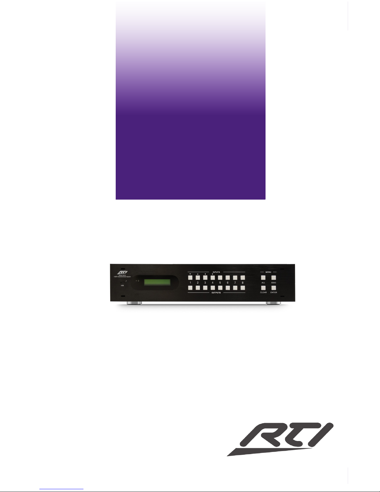
VHD-8 FRONT PANEL
1. Firmware
Micro USB port for update rmware.
2. Power Indicator
Lit when power is on.
3. LCD Indicator
For real-time system status.
4. INPUTS/Menu buttons
• Normal mode: Input buttons, ranging from “1” to “8”.
• Inquire mode: Press “ENTER” for more than 3 seconds to enter this mode.
To select dierent menus, press:
To select dierent options, press:
5. OUTPUTS/EDID Management buttons
• Normal mode: Output buttons, ranging from “1” to “8”.
• Output 1~4 support synchronous local HDMI output.
• EDID Invoking mode: press and hold EDID button for 3 seconds or more to enter this
mode, buttons 1~6 correspond to the 6 embedded EDID data separately. Press any of
the 6 buttons to invoke embedded EDID data.
6. MENU Buttons
• ALL output button: To transfer one input to all outputs.
Example: To transfer both AV signals from input channel No.1 to all output channels.
Operation: Press buttons in this order “1” + “ALL” + “ENTER”
• EDID management button: manually capture and copy the EDID data from output
device to input port.
Example: To capture and copy the EDID data from output channel No.4 to input
channel No.2.
Operation: Press buttons in this order “EDID” + “2” + “4” ~ Press button “2” in
INPUTS area, “4” in OUTPUTS area.
• CLEAR: Withdraw an operation like switching output channel, learning EDID data
before it comes into eect. The matrix will return to the previous status.
• ENTER: Conrm operation. Press and hold it for 3 seconds to enter in Inquiry mode.
CLEAR
ALL
OUTPUTS
INPUTS
MENU
1 2
3
4
5
6 7 8
ENTER
EDID
USB
Model
VHD-8
HDBTVideo Distribution System
1 2
3
4
6
5
Page 12
8x8 HDBT Video Matrix Switch
VHD-8
12
CLEAR
ALL
OUTPUTS
INPUTS
MENU
1 2
3
4
5
6 7 8
ENTER
EDID
USB
Model
VHD-8
HDBTVideo Distribution System
IR ALL IN
IR CTRL
4
HDMI 4
HDMI 3
3
HDMI 6 HDMI 5
6
5
HDMI 8 HDMI 7
8
7
HDMI 2 HDMI 1
INPUT
INPUT INPUT INPUT
2
1
HDBT
OUTPUT 1 OUTPUT 2 OUTPUT 3 OUTPUT 4 OUTPUT 5 OUTPUT 6 OUTPUT 7 OUTPUT 8
HDMI
HDMI
HDMI
HDMI
AC100V-240V
IR IN
IR IN IR IN IR IN
AUDIO
LR
Model
VHD-8
Remote Technologies Incorporated
P/N S/N
20-210175-18
ETHE RNET
HDBT
HDBT
HDBT
HDBT
HDBT
HDBT
N27917
HDBT
AUDIO
LR
AUDIO
LR
AUDIO
LR
AUDIO
LR
AUDIO
LR
AUDIO
LR
AUDIO
LR
RS232
CLEAR
ALL
OUTPUTS
INPUTS
MENU
1 2
3
4
5
6 7 8
ENTER
EDID
IR ALL IN
IR CTRL
HDBT
OUTPUT 1
OUTPUT 2 OUTPUT 3 OUTPUT 4 OUTPUT 5 OUTPUT 6 OUTPUT 7 OUTPUT 8
HDMI
HDMI
HDMI
HDMI
AC100V-240V
AUDIO
LR
Model
VHD-8
Remote Technologies Incorporated
P/N S/N
20-210175-18
ETHE RNET
HDBT
HDBT
HDBT
HDBT
HDBT
HDBT
N27917
HDBT
AUDIO
LR
AUDIO
LR
AUDIO
LR
AUDIO
LR
AUDIO
LR
AUDIO
LR
AUDIO
LR
RS232
MENU
ENTER
EDID
IR ALL IN
IR CTRL
AC100V-240V
Model
VHD-8
Remote Technologies Incorporated
P/N S/N
20-210175-18
ETHE RNET
N27917
RS232
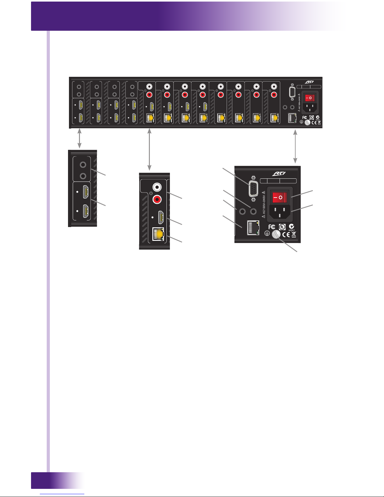
VHD-8 REAR PANEL
CHAPTER 2 | DESCRIPTION
1. IR IN (1-8)
3.5mm Mono Mini: Connect to the IR output of a control processor for control of a
remote device via the designated VHR-1 HDBaseT receiver output.
2. HDMI INPUTS (1-8)
HDMI input ports, 8 in total, type A female HDMI connector, connect with HDMI video
source devices.
3. OUTPUTS
a. AUDIO - RCA: Two de-embedded audio output jacks (left and right channels) for
connection to speakers or the inputs of an audio distribution system.
b. HDMI Port: HDMI output port, connect with HDMI output devices. To split HDMI
output for local monitoring.
c. HDBaseT - RJ45: Works with VHR-1 HDBaseT receiver. Transmits HDMI@1080p, IR
& RS232 up to 230 feet (70m) over a Cat5e/6 cable (115ft/35m at 4Kx2K).
NOTE: The Cat5 cables for HDBaseT must be straight-through, using T568A or T568B
standard.
CLEAR
ALL
OUTPUTS
INPUTS
MENU
1 2
3
4
5
6 7 8
ENTER
EDID
USB
Model
VHD-8
HDBTVideo Distribution System
IR ALL IN
IR CTRL
4
HDMI 4
HDMI 3
3
HDMI 6 HDMI 5
6
5
HDMI 8 HDMI 7
8
7
HDMI 2 HDMI 1
INPUT INPUT INPUT INPUT
2
1
HDBT
OUTPUT 1 OUTPUT 2 OUTPUT 3 OUTPUT 4 OUTPUT 5 OUTPUT 6 OUTPUT 7 OUTPUT 8
HDMI
HDMI
HDMI
HDMI
AC100V-240V
IR IN IR IN IR IN IR IN
AUDIO
LR
Model
VHD-8
Remote Technologies Incorporated
P/N S/N
20-210175-18
ETHER NET
HDBT
HDBT
HDBT
HDBT
HDBT
HDBT
N27917
HDBT
AUDIO
LR
AUDIO
LR
AUDIO
LR
AUDIO
LR
AUDIO
LR
AUDIO
LR
AUDIO
LR
RS232
1
2
a
3
b
c
4
7
5
8
6
9
10
Page 13
13
It’s Under Control
®
CHAPTER 2 | DESCRIPTION
VHD-8 REAR PANEL
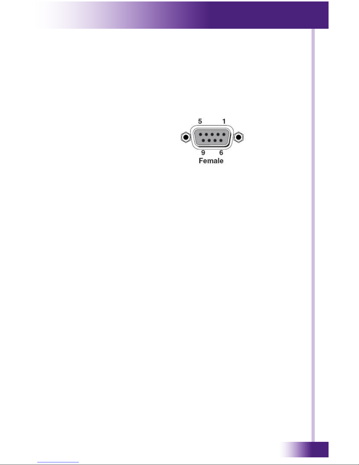
4. RS232
D-Connector 9-pin: Connect to the serial output of a control processor for control of the
VHD-8 via RS232 communication.
RS232 port pinout diagram:
No. Pin Function
1 N/u Unused
2 Tx Transmit
3 Rx Receive
4 N/u Unused
5 Gnd Ground
6 N/u Unused
7 N/u Unused
8 N/u Unused
9 N/u Unused
5. IR CTRL
3.5mm Mono Mini: Connect to control processor IR output for control of the VHD-8.
6. IR ALL IN
3.5mm Mono Mini: IR control signal input port, connect to the IR output of a control
system IR output. Passes through IR signal to all VHR-1 HDBaseT IR ports to control
remote devices.
7. ETHERNET
RJ45 Jack: Connect to an Ethernet network for control of the VHD-8 via TCP/IP.
8. POWER SWITCH
Press the switch to turn on/o the matrix.
9. POWER JACK
Connect to an AC 100V~240V power adapter via the included power cord.
10. GROUND
Connect to ground.
Page 14

8x8 HDBT Video Matrix Switch
VHD-8
14
CHAPTER 3 | INSTALLATION AND OPERATION
PRECAUTIONS
1) System should be installed in a clean environment and has a proper temperature and
humidity.
2) All of the power switches, plugs, sockets and power cords should be insulated.
3) All devices should be connected before powering on VHD-8.
RACK MOUNT INSTALLATION
The VHD-8 can be mounted in a component rack using the included rack mounting ears.
Align the rack mounting ears with the screw holes located on the sides of the VHD-8 near
the front. Fasten the rack ears to the VHD-8 using the screws (supplied). Remove feet
before mounting in a rack.
NOTE: To maintain proper ventilation, it is recommended that you leave a rack space above
and below the VHD-8.
CONNECTION PROCEDURE
AV INPUTS/OUTPUTS
1) Connect HDMI sources (e.g. DVD) to HDMI inputs of VHD-8 with HDMI cables.
2) Connect displays (e.g. HDTV) to HDMI outputs of VHD-8 with HDMI cables.
3) Connect speakers or audio distribution system to AUDIO output ports.
4) Connect VHR-1 HDBaseT receiver to the VHD-8 HDBaseT ports with Cat5e/6 cable.
NOTE: The VHR-1 is PoC (Power over Cable) compatible. It can be powered over the
same Cat5e/6 cable or a local power supply may be used.
CONTROL OPTIONS
5) Connect the RS232 port (9 pin female D) of VHD-8 to a control system processor (see
pinout diagram in previous section).
6) Connect the IR CTRL 3.5mm mono mini jack to a control processor IR output for control
of the VHD-8.
7) Connect IR IN (1-8) or IR ALL IN 3.5mm mono mini jacks to a control processor for IR
control of devices via the VHR-1.
8) Connect to an Ethernet network for control of the VHD-8 via TCP/IP over Cat5e/Cat6
cable.
POWER
9) Connect the included power cable to VHD-8 and press power switch to “on” position.
CLEAR
ALL
OUTPUTS
INPUTS
MENU
1 2
3
4
5
6 7 8
ENTER
EDID
USB
Model
VHD-8
HDBTVideo Distribution System
Page 15
15
It’s Under Control
®
CHAPTER 3 | INSTALLATION AND OPERATION
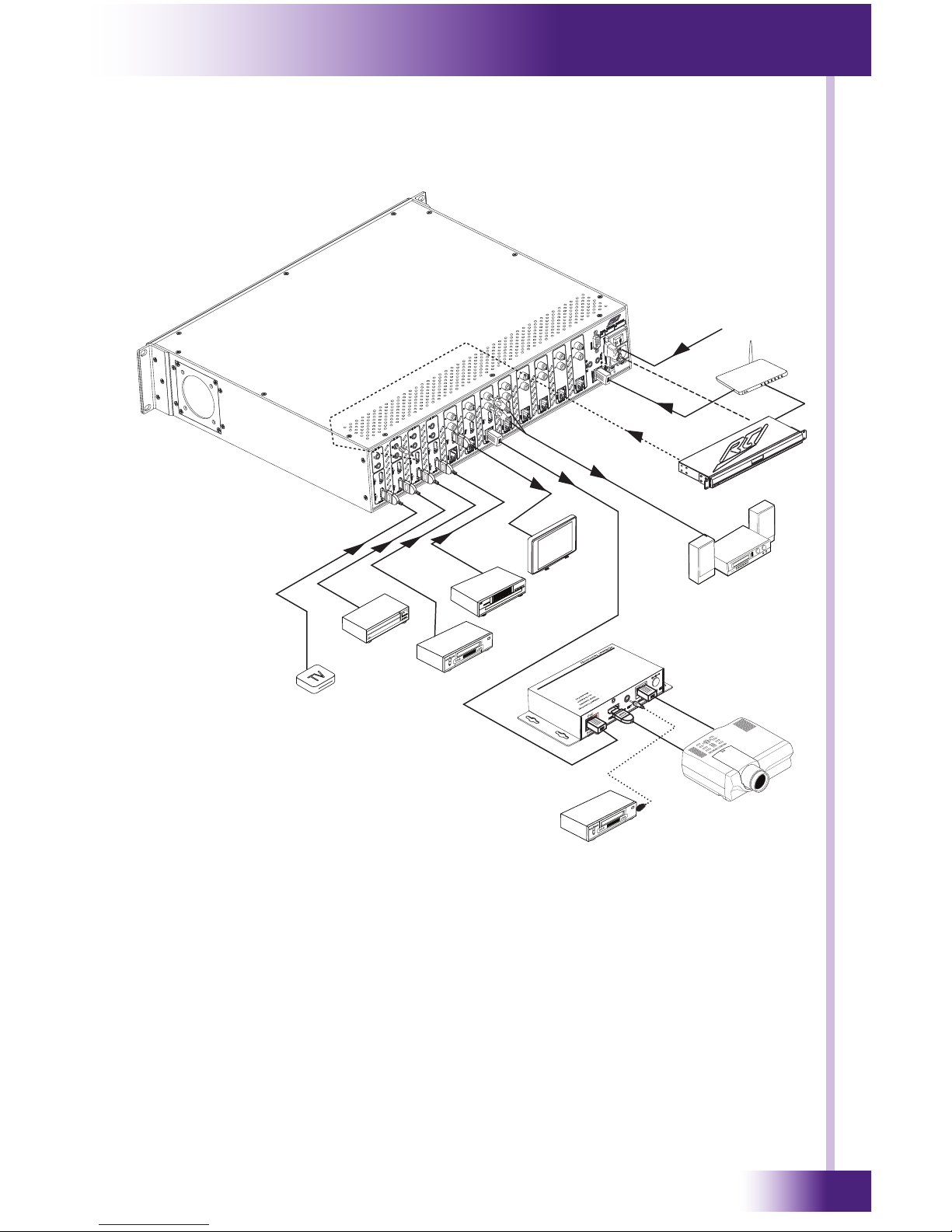
CONNECTION DIAGRAM
MEDIA
SERVER
SAT
DVD
VHR-1 Receiver
Audio Distribution
Projector
HDTV
LAN
Processor
STREAMER
DVD
Power
Page 16

8x8 HDBT Video Matrix Switch
VHD-8
16
CHAPTER 3 | INSTALLATION AND OPERATION
FRONT PANEL CONTROL
The VHD-8 provides control via the front panel buttons. Below is an introduction to the
system operations.
Switching I/O connection
1) To convert one input to an output:
Operation: Select INPUT + OUTPUT + ENTER
Example: Input 1 to Output 2
2) To switch an input to several outputs:
Operation: Select INPUT + OUTPUT + OUTPUT + ENTER
Example: Switch input 2 to output 2, 4
3) To switch an input to all outputs:
Operation: Select INPUT + ALL + ENTER
Example: Switch input 1 to all outputs
Note: Indicators of the pressed buttons will blink green for three times if the switch is
done, then turn o. If the switch operation failed, they will be o immediately.
EDID MANAGEMENT
The VHD-8 features EDID management to maintain compatibility between all devices.
It can be controlled via EDID learning and EDID invoking.
EDID Learning (from output):
1) One input port learns the EDID data of one output port
Operation: Press EDID, Select INPUTS + OUTPUTS + ENTER.
Example: Input 2 learns EDID data from output 4
INPUTS
1
OUTPUTS
2
ENTER
INPUTS
1
OUTPUTS
2
ENTER
OUTPUTS
4
INPUTS
2EDID
OUTPUTS
4
ENTER
INPUTS
1
ALL ENTER
Page 17

17
It’s Under Control
®
2) All input ports learn EDID data from one output port
Operation: Press EDID + ALL + OUTPUTS +ENTER
Example: All input ports learn EDID data from output 4
Note: Indicators of the pressed buttons will blink green for three times if the switch is
done, then turn o. If the switch operation failed, they will be o immediately.
EDID INVOKING
There are six types of embedded EDID data. The chart below illustrates the detailed
information of the embedded EDID data:
Press and hold EDID for 3 seconds to enter EDID invoking mode. In this mode, use output
buttons 1-6 to switch among the 6 embedded EDID data. Then press ENTER to conrm
invoking.
Format: Press and hold EDID for 3 seconds + INPUTS + OUTPUTS 1-6 + ENTER.
Operations:
1) Invoke embedded EDID data for one input
Operation: Press EDID (hold for 3 seconds) + INPUTS + OUTPUTS +ENTER
Example: Set the EDID data of INPUT 2 to the forth type of embedded EDID data:
Note: Indicators of the pressed buttons will blink green for three times if the switch is
done, then turn o. If the switch operation failed, they will be o immediately.
CHAPTER 3 | INSTALLATION AND OPERATION
OUTPUTS
4
ENTERALLEDID
Output Button EDID Data
1 1080P 2D 2CH
2 1080P 3D 2CH
3 1080P 2D Multichannel
4 1080P 3D Multichannel
5 3840x2160 2D (30Hz)
6 4096x2160 2D 30Hz
INPUTS
2
EDID
OUTPUTS
4
ENTER
Hold for 3
seconds
To switch
to the 4th
EDID data
Page 18

8x8 HDBT Video Matrix Switch
VHD-8
18
CHECK STATUS INQUIRY
Press and hold ENTER for 3 seconds, it will enter into system inquiry menu. Use Left and
Right direction buttons to navigate checking the previous/next items.
Output Check
1) Press any output button to check its corresponding input.
Example: Determine the corresponding input for output 2. (Presume Output 2 corresponds
to Input 1.)
Operation: Press Output 2 button, LCD screen display AV: 1->2, and indicators of input 1
and output 2 turn on and last for 3 seconds, then output 2 corresponds to input 1.
CLEAR OPERATION
When you switch output channel, learn EDID data, or set EDID data, pressing the CLEAR
button will withdraw the operation, before you press ENTER to complete an operation.
When you press CLEAR, the matrix will return to the previous status.
CHAPTER 3 | INSTALLATION AND OPERATION
FUNCTION ITEMS EXAMPLE DESCRIPTION
Check the connection status
of inputs
IN 1 2 3 4
CONNECT Y Y N N
Y means the corresponding
port is connected with an
input device, N means not.
Check the connection status
of outputs
OUT 1 2 3 4
CONNECT Y Y N N
Y means the corresponding
port is connected with an
output device, N means
not.
Correspondence between
inputs and outputs
OUT 1 2 3 4
IN 1 2 3 3
Shows the correspondence
between the 8 inputs and 8
outputs
Check if the input is with
HDCP
IN 1 2 3 4
HDCP Y Y N N
Y means the input signal is
with HDCP, N means not.
Check if the output is with
HDCP
OUT 1 2 3 4
HDCP Y Y N N
Y means the output signal
is with HDCP, N means not.
Check the output resolution Resolution
Out 1 1920x1080
Use the UP and DOWN
direction button to check all
the 8 output resolutions.
CLEAR
Page 19

19
It’s Under Control
®
CHAPTER 3 | INSTALLATION AND OPERATION
IR CONTROL
• IR Control of VHD-8 - CTRL IN
This 3.5mm mono mini-jack is for infrared control of the VHD-8 from a control system.
A discrete set of IR codes is available within the RTI Integration Designer programming
software or on the RTI website (RTI dealer section).
NOTE: Mini-jack is mono with tip = IR+, ring=Gnd.
• IR Control of Remote Devices - IR IN (Ports 1-8)
Discrete control of remote devices is possible via the IR IN 3.5 mono mini-jack associated
with IR IN 1-8. The IR signal is delivered to the VHD-8 via an RTI control processor and is
sent over Cat5e/Cat6 cable to a VHR-1 HDBaseT receiver. An infrared emitter is wired to
the VHR-1 IR OUT port and wired to the controlled device. See VHR-1 installation guide for
detailed information.
Note: The IR signal connected to IR IN must be with IR carrier.
• IR Control of Remote Devices - IR ALL IN
Control of remote devices is also possible via the IR ALL IN 3.5 mono mini-jack on the
VHD-8. The IR signal is delivered to the VHD-8 via an RTI control processor and is sent
over Cat5e/Cat6 cable to all connected VHR-1 HDBaseT receivers. All infrared emitters
wired to the VHR-1 IR OUT ports will receive the signal. See VHR-1 installation guide for
detailed information.
Note: The IR signal connected to IR ALL IN must be with IR carrier.
RS-232 CONTROL
• RS-232 Control of VHD-8 - RS232 port
A DB-9 jack oers RS-232 control of the VHD-8 from an RTI or third-party control system.
A set of RS-232 codes is built into the Integration Designer programming software and a
two-way driver is available on the RTI website (dealer section).
NOTE: DO NOT use both RS-232 and IP for control simultaneously. Using both control
methods at the same time will aect control reliability.
Connection Settings:
Baud rate: 9600 • Data bits: 8 • Parity: None • Stop bits: 1
DB-9 Jack Pinout:
Pin 2 TXD Transmit Data
Pin 3 RXD Receive Data
Pin 5 GND Ground
• RS-232 Control of Remote Devices
RS-232 control of remote devices is possible via the VHD-8 using an RTI control system
and a VHR-1 HDBaseT receiver. To implement, go to the VHD-8 driver conguration in
Integration Designer and dene the RS-232 string, baud rate and the VHD-8 port that the
VHR-1 is connected to. See VHR-1 reference guide for cable installation information.
FIRMWARE UPDATE VIA USB
To perform rmware updates via the USB port on the front panel:
Step1. Visit the rmware update section of the RTI Dealer website (rticorp.com/dealer) to
download the latest version to a PC.
Step2. Connect a USB cable to the USB ports of VHD-8 and the PC.
Step3. Double-click the rmware update software icon and follow the onscreen instructions.
NOTE: Do NOT unplug the USB cable during the update process or damage to the unit may
result.
Page 20

8x8 HDBT Video Matrix Switch
VHD-8
20
CHAPTER 3 | INSTALLATION AND OPERATION
ETHERNET (IP) CONTROL
The built-in Ethernet port allows control of the VHD-8 via an Ethernet network (LAN)
from an RTI XP processor. Conguration of the VHD-8 networking is done through a web
interface which is accessible through any web browser
NOTES: For IP control:
• DO NOT use both RS-232 and IP for control simultaneously. Using both control methods
at the same time will aect control reliability.
• The RTI control system must have a two-way driver running on an XP processor.
• The RTI control system and VHD-8 must be connected to the same Ethernet network
(LAN).
CONNECTION TO THE ETHERNET NETWORK
Wire the VHD-8 to the Ethernet network using Cat5 cable with the RJ45 termination and
power the unit on. The network router will assign an IP address to the VHD-8 automatically
and allow it to join the network.
NOTES:
• The VHD-8 is set to use DHCP by default.
• Router must have DHCP enabled.
CONFIGURING THE VHD-8 USING THE WEB INTERFACE
The VHD-8 web interface is accessible via a standard web browser (Chrome®, Internet
Explorer®, Firefox® , Safari® etc) on a PC, tablet or smartphone.
The web interface is used for conguring network settings (IP address and Network ID).
ACCESSING THE WEB INTERFACE
To access the web interface, rst determine the IP address that was assigned to the VHD-8
by the network router which can be found by looking for UPNP devices on the network.
NOTE: If using Windows XP, you may need to enable viewing of UPNP devices and
“Windows Discovery”.
• Click on My Network Places
• If UPNP devices are not displayed, under Network Tasks, click on “Show icons for
networked UPNP devices”. Click yes to allow the installation wizard.
To view UPNP devices on the network, go to the “network” area in your version of
Windows.
• In the “Computer” tab under the Start Menu.
• Click on “Network”.
• On the right side window, scroll down to “Other Devices”.
• Find the VHD-8 in the list of devices and double click on the icon to open the web
interface.
OR
• The VHD-8 icon will display the IP address it is using. Open a web browser on your PC,
tablet or smartphone and type the IP address into the browser address bar.
Example: http://192.168.0.15
Page 21

21
It’s Under Control
®
CHAPTER 3 | INSTALLATION AND OPERATION
WEB INTERFACE - LOGIN
To access the web interface, enter the password and press LOGIN
NOTE: The default password is: rti
Page 22

8x8 HDBT Video Matrix Switch
VHD-8
22
CHAPTER 3 | INSTALLATION AND OPERATION
WEB INTERFACE - NETWORK CONFIGURATION PAGE
Upon logging into the web interface the Network Conguration page will be displayed.
IP ADDRESS CONFIGURATION
IMPORTANT NOTES:
• Setting a static IP address is not necessary. The RTI two-way driver uses the UPNP
name of the VHD-8 to nd it on the network.
• Setting a static IP address and clicking “Update Settings” will cause the web interface
to no longer be displayed in your web browser. Enter the new static IP address into
your web browser address bar to access the web interface again.
To set the static IP address:
1. Select Address Type (set to DHCP by default): click this button and select “Static IP”
from the drop down list.
2. Enter Static IP Address: Enter the static IP address.
3. Enter Subnet Mask: Enter the network subnet used by the VHD-8 and RTI XP
processor.
4. Enter Default Gateway: Enter the IP address of the network gateway.
5. Click on the “Update Settings” button to save these settings.
NETWORK IDENTIFICATION
This section allows you to change the name of the device as it shows up on the network
and list of UPNP devices.
1. Unit Name: Enter a new VHD-8 name
2. Click on the “Update Settings” button to save these settings.
Page 23

23
It’s Under Control
®
CHAPTER 3 | INSTALLATION AND OPERATION
WEB INTERFACE
Page 24

8x8 HDBT Video Matrix Switch
VHD-8
24
CHAPTER 4 | SPECIFICATIONS
Power Supply 100V~240V AC, Power Consumption 103W (full load)
Mounting Rack mount or free standing
Dimensions
(W x H x D)
17.1” (437mm) x 3.4” (87.8mm) x 14.9” (380mm) (2U high,
full rack width)
Weight 5.4lb (2.45kg)
Operational Temperature 32°F - 104°F (0°C – 40°C)
Humidity 10% to 90% Non-Condensing
Warranty Three Years (Parts & Labor)
All specications subject to change without notice.
GENERAL
Video Input Eight HDMI
Input Level T.M.D.S. 2.9V~3.3V
Input Impedance 100Ω (Dierential)
Video Output Four HDMI, Eight HDBaseT (RJ45)
Output Level T.M.D.S. 2.9V~3.3V
Output Impedance 100Ω (Dierential)
Gain 0dB
Bandwidth 10.2Gbit/s
Video Signal HDMI (or DVI-D)
Resolution Range Up to 4K x 2K@30Hz
HDBaseT Transmission
Distance
1080P@60Hz ≤230ft (70m)
4Kx2K@30Hz ≤115ft (35m)
Switching Speed 200ns (Max.)
EDID Management In-built EDID data and manual EDID management
HDCP Supports HDCP 1.4, auto and manual HDCP management.
Audio Output Stereo audio, Eight RCA Jacks
AUDIO/VIDEO
Page 25

25
It’s Under Control
®
All specications subject to change without notice.
CHAPTER 4 | SPECIFICATIONS
IR Control One, 3.5mm jack (IR CTRL), compatible with industry
standard IR repeaters and receivers
Remote Source IR Inputs Eight discrete (IR IN), One universal (IR ALL IN), 3.5mm
jacks
Panel Control Twenty Front Panel buttons
Serial (RS-232) Port One, Bi-directional Female DB-9
Ethernet Port One, 10/100Base-T, RJ45 Connection
USB One, Micro USB, Female
CONTROL
Page 26

8x8 HDBT Video Matrix Switch
VHD-8
26
If you are having problems with your VHD-8, please read the information below before
contacting technical support.
If you continue to have problems, see Chapter 6 for more information on contacting RTI
technical support.
SYMPTOM:
Color loss or no video signal output
CAUSES:
1) The connecting cables may not be connected correctly or it may be broken.
SOLUTIONS:
1) Check whether the cables are connected correctly and in working condition.
SYMPTOM:
No output image when switching
CAUSES:
1) No signal at the input/output end
2) Fail or loose connection
3) Input source is with HDCP while the HDCP compliance is switched o
4) The display doesn’t support the input resolution
SOLUTIONS:
1) Check with oscilloscope or multimeter if there is any signal at the input/ output end.
2) Make sure the connection is good
3) Send command /%[Y]/[X]:1.
4) Switch for another input source or enable the display to learn the EDID data of the
input.
SYMPTOM:
Cannot control the device via front panel buttons
CAUSES:
1) Front panel buttons are locked
SOLUTIONS:
1) Send command /%Unlock; or select unlock in GUI interface to unlock
SYMPTOM:
Power Indicator remains o when powered on
CAUSES:
1) Fail or loose power connection
SOLUTIONS:
1) Check whether the cables are connected correctly
SYMPTOM:
EDID management does not work normally
CAUSES:
1) The HDMI cable is broken at the output end.
SOLUTIONS:
1) Change for another HDMI cable which is in good working condition.
SYMPTOM:
There is a blank screen on the display when switching
CAUSES:
1) The display does not support the resolution of the video source.
SOLUTIONS:
1) Switch again.
2) Manage the EDID data manually to make the resolution of the video source
automatically compliant with the output resolution.
CHAPTER 5 | TROUBLESHOOTING
Page 27

27
It’s Under Control
®
CHAPTER 5 | TROUBLESHOOTING
SYMPTOM:
No RS232 control of VHD-8
CAUSES:
1) Faulty wiring
2) Incorrect string
3) Wrong RS232 parameters
SOLUTIONS:
1) Verify cable and check RS-232 pinout
2) Verify string from manual.
3) Type in correct RS232 communication parameters: Baud rate:9600; Data bit: 8; Stop
bit: 1; Parity bit: none
SYMPTOM:
No IR control of VHD-8
CAUSES:
1) Faulty wiring
2) IR signal level
SOLUTIONS:
1) Verify all wiring & terminations - IR jacks are 1/8” mono, tip = IR+, ring=Gnd.
2) Adjust IR signal going into VHD-8.
3) Verify connection is to IR CTRL input jack.
SYMPTOM:
No IR control via VHR-1
CAUSES:
1) Faulty wiring
2) IR signal level
3) IR emitter or IR emitter placement
SOLUTIONS:
1) Verify all wiring & terminations - IR jacks are 1/8” mono, tip = IR+, ring=Gnd.
2) Adjust IR signal going into VHD-8.
3) Verify IR emitter is working and properly placed.
SYMPTOM:
Static becomes stronger when connecting the video connectors
CAUSES:
1) Bad grounding
SOLUTIONS:
1) Check the grounding connections.
SYMPTOM:
Cannot control the device by RS232, IR or front panel buttons
CAUSES:
1) The VHD-8 has failed
SOLUTIONS:
1) See service and support section of this guide
Page 28

8x8 HDBT Video Matrix Switch
VHD-8
28
For news about the latest updates, new product information, and new accessories, please
visit our web site at:
www.rticorp.com
CONTACTING RTI
For general info, you can contact RTI at:
Tel. (952) 253-3100
Fax (952) 253-3131
info@rticorp.com
RTI TECHNICAL SUPPORT
At RTI, customer service and satisfaction is an utmost priority. If you are encountering any
problems or have a question about your RTI product, please contact RTI Technical Support
for assistance.
RTI provides technical support by telephone, fax or e-mail. For the highest quality service,
please have the following information ready, or provide it in your fax or e-mail.
Your Name
Company Name
Telephone Number
E-mail Address
Product model and serial number (if applicable)
If you are having a problem with hardware, please note the equipment in your system, a
description of the problem, and any troubleshooting you have already tried.
If you are having a problem with software, please note what version you have installed, the
operating system on your PC, a description of the problem, and any troubleshooting you
have already tried.
If you are calling about a software or programming question or problem, please be at you
computer when you place your call. This will considerably speed up the troubleshooting
process.
For technical support or assistance with your VHD-8, software, or accessories, contact RTI
at:
(952) 253-3137
support@rticorp.com
www.rticorp.com
For questions regarding service or repair, contact RTI at:
(952) 253-3136
service@rticorp.com
www.rticorp.com
Please do not return products to RTI without return authorization.
CHAPTER 6 | SERVICE AND SUPPORT
Page 29

29
It’s Under Control
®
CHAPTER 6 | SERVICE AND SUPPORT
Shipment of VHD-8 for Service
RTI will pay all labor and material expenses for all repairs covered by this product’s
warranty. If necessary repairs are not covered by warranty, or if a unit is examined which is
not in need of repair, you may be charged for the repairs or examination.
If it is necessary to ship the VHD-8 for service:
Please pack it securely (we suggest that it be insured).
Do not include accessories such as power cords or manuals unless
instructed to do so.
You must pay any shipping charges incurred in getting your VHD-8 to RTI. RTI will pay
reasonable return shipping charges via a carrier of our choice to any destination within the
United States if the repairs are covered under warranty.
A copy of the original dated sales receipt must be provided whenever warranty service is
required. You will need this receipt to establish the date of purchase.
Page 30

8x8 HDBT Video Matrix Switch
VHD-8
30
NOTES
Page 31

31
It’s Under Control
®
Page 32

8x8 HDBT Video Matrix Switch
VHD-8
32
Remote Technologies Incorporated
5775 12th Avenue East, Suite 180
Shakopee, MN 55379
Tel: 952-253-3100
Fax: 952-253-3131
www.rticorp.com
© 2018 Remote Technologies Inc. All rights reserved. Printed in Taiwan.
It’s Under Control
®
 Loading...