

Page 1
4707.001199#1.0B RTI Slit Cameara User’s Manual
2015-02-11
RTI
Slit Camera
User’s Manual – English – Version 1.0B
Page 2

2
1. Introduction
About this Manual
RTI Slit Camera User’s Manual 1.0B
Table of Contents
1. Introduction ........................................................................................3
1.1. About this Manual .................................................................................. 3
1.2. Introduction to the Slit Camera ............................................................... 3
2. Description of the RTI Slit Camera ....................................................4
2.1. Setting Up the Slit Camera for the First Time .......................................... 5
2.2. Hardware and Specifications .................................................................. 5
2.2.1. Slit Camera ................................................................................... 5
2.2.2. Dimensions ................................................................................... 5
2.3. Standards and Compliances .................................................................. 6
2.3.1. Waste Electrical and Electronic Equipment (WEEE) ....................... 6
3. Theory of Focal Spot Reproduction ..................................................7
3.1. Theory................................................................................................... 7
3.2. Why measure the focal spot? ................................................................. 8
4. X-Ray Tube Focal Spot Measurements ........................................... 11
4.1. Purpose .............................................................................................. 11
4.1.1. Equipment Recommended for Focal Spot Measurements ............. 11
4.2. Focal Spot Test Stand Alignment ......................................................... 11
4.3. Slit Measurement Using Film and Magnifier Lens .................................. 12
4.4. Slit Measurement Using Digital Image .................................................. 13
4.4.1. Evaluation using ImageJ .............................................................. 13
5. Word List .......................................................................................... 16
6. Appendix A ....................................................................................... 19
6.1. A.1. Nominal Focal Spot Size - IEC 60336 ............................................ 19
7. Index ................................................................................................. 21
Page 3

1. Introduction
3
About this Manual
1.0B RTI Slit Camera User’s Manual
1. Introduction
1.1. About this Manual
This manual is divided into a few main parts.
1. A general description of the Slit Camera.
2. Descriptions and hints on performing measurements.
3. Troubleshooting tip, and FAQ.
Typographical Rules
Terms in bold face are references to texts on screenshots, like buttons and texts, and
menu items. Other terms are italicized.
1.2. Introduction to the Slit Camera
Congratulations to your purchase of the Slit Camera from RTI. You have now in your
hand a quality tool for focal spot size evaluation. It has been carefully designed to meet
the needs of modern X-ray systems.
If you have questions, comments, or feel that some functionality is missing, you are
welcome to contact us at RTI Electronics at sales@rti.se. You can of course also call
(see notice section for details).
The Slit Camera does not come with any evaluation tool.
RTI recommends digitalizing the slit image and using an image
evaluation tool to measure in the image. An example of such software is
ImageJ, http://imagej.nih.gov/ij/
Page 4
4
2. Description of the RTI Slit Camera
Introduction to the Slit Camera
RTI Slit Camera User’s Manual 1.0B
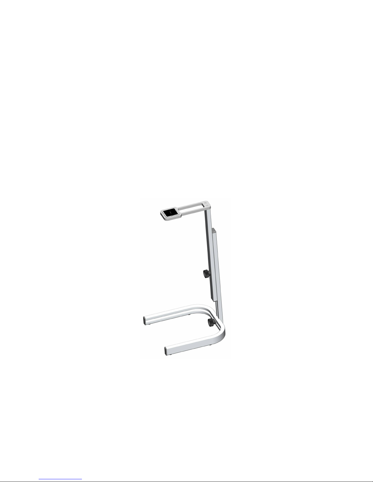
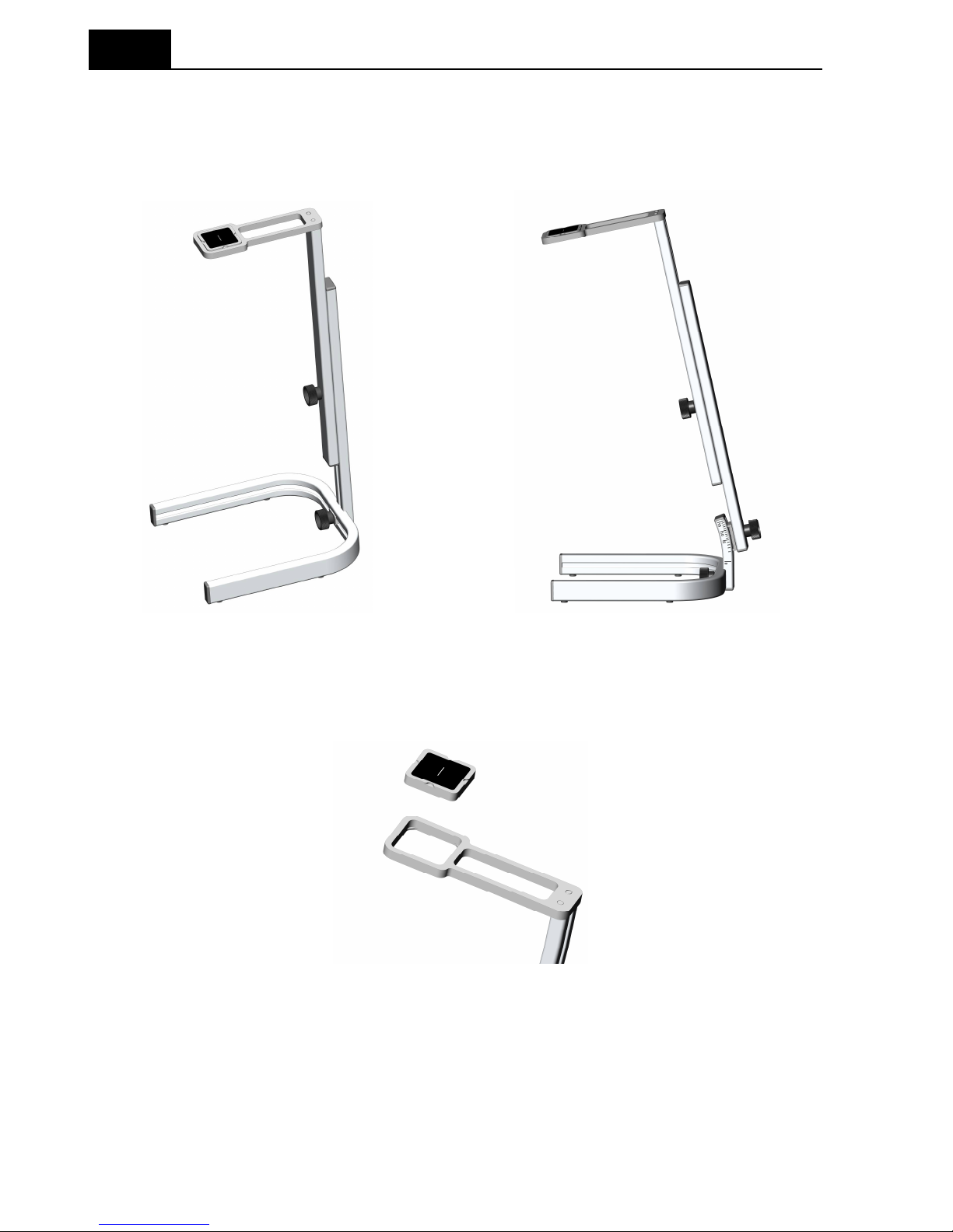
2. Description of the RTI Slit Camera
The RTI Slit Camera for x-ray focal spot measurement comes with a stand with an
adjustable rod. Optionally also a tilting device is available.
Figure 2-1 Slit Camera with (left) and without (right) the optional tilting device.
The Slit Camera can be rotated 90 degrees in the Slit Camera holder. See figure 2-2
below. The 90 degree rotation simplifies the measurement of length and width
measurements of the focal spot since the slit only have to be aligned once.
Figure 2-2 The Slit Camera can be rotated by means of 90 degrees.
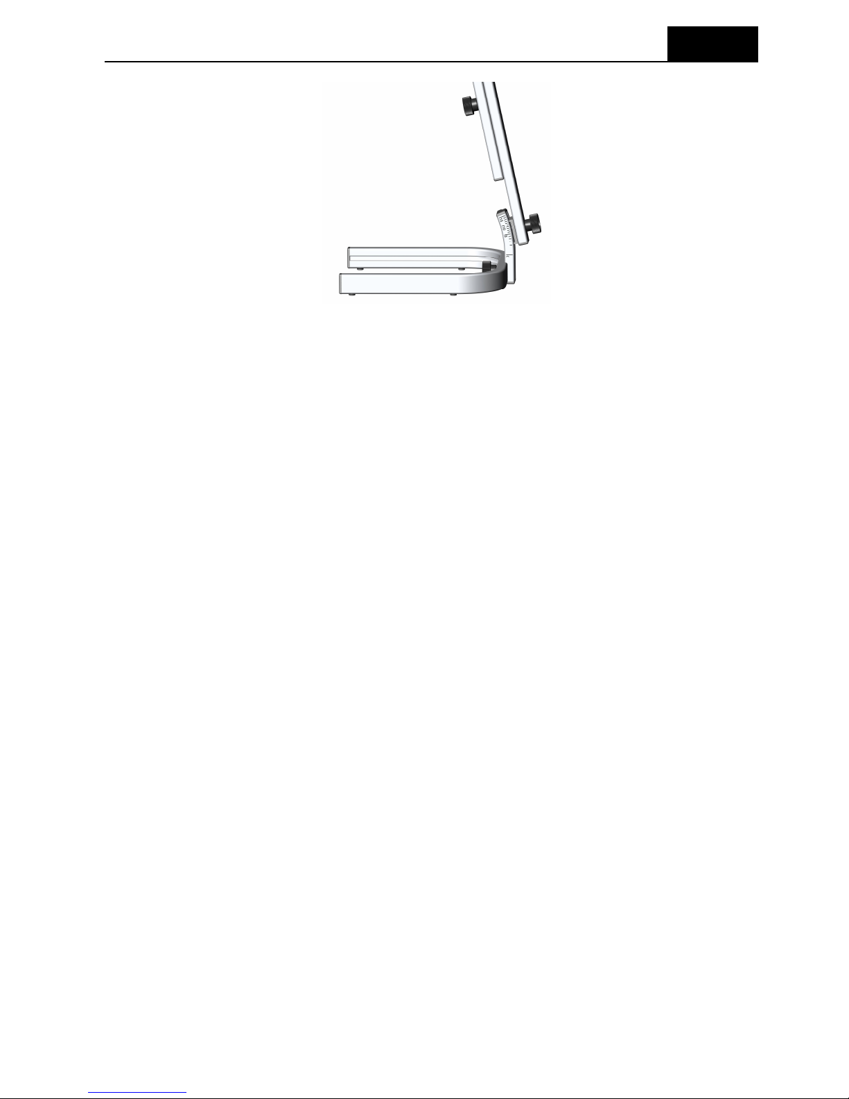
The optional tilting device enables measurements where the reference position is not
orthogonal to the image plane, which is normal in mammography. See figure 2-3 below.
Page 5
2. Description of the RTI Slit Camera
5
Setting Up the Slit Camera for the First Time
1.0B RTI Slit Camera User’s Manual
Figure 2-3 The optional Tilting Device is ideal for use in mammography where the
reference position normally is not orthogonal to the breast support.
2.1. Setting Up the Slit Camera for the First Time
Before you use your Slit Camera for the first time, mount the Slit Camera and the stand
to make sure that all mechanical parts fits together, and that no parts have been
damaged during transportation.
2.2. Hardware and Specifications
All specifications can be changed without prior notice. RTI assumes no responsibility
for any errors or consequential damages that may result from the misuse or
misinterpretation of any information contained in these specifications.
2.2.1. Slit Camera
Supporting standards IEC 60336
Tube focal spot types Radiographic, CT, Mammographic, Dental
kV range 18 - 150 kV
Enlargement factor E 0.8 - 5
E = n/m, where:
n = slit to detector distance
m = slit to focal spot distance
Measurement range 0.1 - 5 mm
2.2.2. Dimensions
Slit holder size 97 x 34 x 6 mm
Slit dimensions 10 µm (as defined by IEC 60336)
Slit material Tungsten (W, 99.9 %)
Page 6
6
2. Description of the RTI Slit Camera
Standards and Compliances
RTI Slit Camera User’s Manual 1.0B
2.3. Standards and Compliances
Hereafter you can find declarations of conformity, as well as documents describing the
intended use of the Slit Camera.
2.3.1. Waste Electrical and Electronic Equipment (WEEE)
The European Union Directive 2002/96/EC on Waste from Electrical and Electronic
Equipment (WEEE) places an obligation on manufacturers, distributors, and retailers to
take back electronics products at the end of their useful life.
The WEEE directive covers all RTI products being sold into the European Union (EU)
as of August 13, 2005. Manufacturers, distributors, and retailers are obliged to finance
the cost of recovery from municipal collection points, reuse, and recycling of specified
percentages per the WEEE requirements.
Instructions for disposal of WEEE by Users in the European Union
The symbol, shown left, is marked on the product, which indicates that this
product must not be disposed of with other waste. Instead, it is the user's
responsibility to dispose of the user's waste equipmen
t by handing it over to
a designated collection point for the recycling of waste electrical and
electronic equipment. The separate collection and recycling of waste
equipment at the time of disposal will help to conserve natural resources
and ensure that it is recycled in a manner that protects human health and
the environment. For more information about where you can drop off your
waste equipment for recycling, please contact your local distributor from
whom you purchased the product.
Page 7
3. Theory of Focal Spot Reproduction
7
Theory
1.0B RTI Slit Camera User’s Manual
3. Theory of Focal Spot Reproduction
3.1. Theory
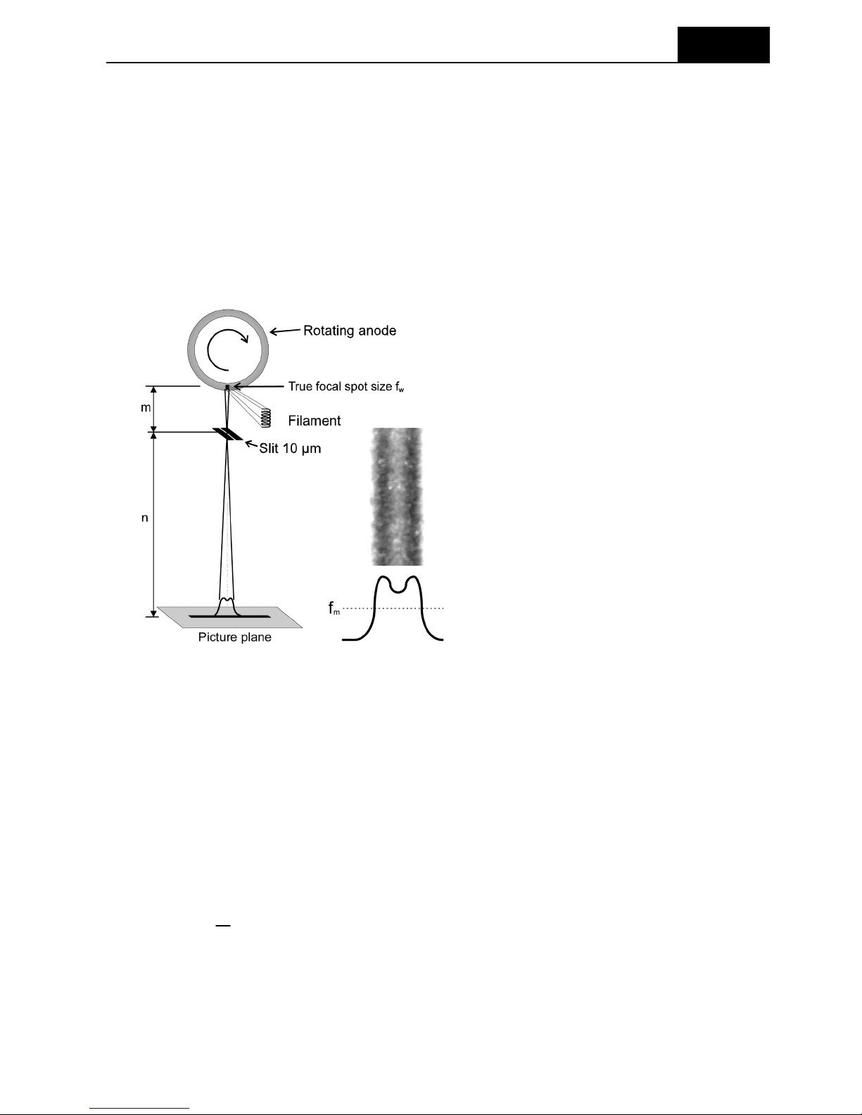
The focal spot is being reproduced (depicted) according to the IEC 60336 [Reference
1], standard through a 10 µm wide slit, and then registered with an image receptor (not
included in the RTI Slit Camera). This is described in figure 1 below. The reproduction
is a one-dimensional “picture” of the focal spot in one direction and a perpendicular
measurement has to be done to get the characteristics of the focal spot in both length
and width directions.
Figure 3–1 Focal spot reproduction. The grey part to the right shows an image taken
with a film in the picture plane. Note the lighter part in the middle indicating the dip
between the two peaks.
As shown in Figure 3–1, you get a measured width of the focal spot, fm. This measured
focal spot is an enlargement of the true focal spot on the anode, fw, magnified by the
factor E, which is n divided by m.
The distance from the true focal spot to the slit is m, and n is the distance from the slit
to the image receptor. The slit width is denoted by s. The true focal spot width can thus
be calculated as:
fw =
m
n
fm (Eq. 3.1)
where
represents the penumbra from the slit.
Page 8

8
3. Theory of Focal Spot Reproduction
Why measure the focal spot?
RTI Slit Camera User’s Manual 1.0B
=
m+n
m
s if the width is calculated at 0 % of the LSF, and
= 0 if the width is calculated at 50 % of the LSF.
Unfortunately the standards specify calculation depending on film blackening, which
represents roughly 10 – 20 % of the LSF. However, normally is so small that you can
forget about it since s is much smaller than f. It () will though not be small for small
mammographic focal spots. The standards specify that you shall use large enlargement
factors for small focal spots, which reduces the a bit but not as much as the reduction
of the focal spot size. The relative error will thus be larger for small focal spots.
This calculation of is done for a square shaped focal spot, it will however do as an
approximation for a focal spot of any shape.
3.2. Why measure the focal spot?
The main aspect of X-ray imaging is to get images of objects. A typical X-ray focal spot
is shown in Figure 3–2. As seen there are two peaks in the width direction, which
depends on the tube filament (cathode). The filament is in this case a metallic thread in
a spiral form. The tube current gives rise to an electron cloud (or space charge) around
the filament. The distribution of the electrons is roughly constant around the filament.
Since the surface of the filament is rounded in one direction there are more electrons
along the sides when viewed from the anode. See Figure 3– below. This distribution
becomes reproduced on the anode when the electrons in the cloud around the filament
accelerate towards the anode by the tube voltage. On many newer X-ray tubes,
especially with small foci, this cannot as easily be seen as new methods to focus the
electron beam and different cathode structures have been developed.
Figure 3–2 Image of the focal spot of a radiographic X-ray tube.
Length
Width
Page 9

3. Theory of Focal Spot Reproduction
9
Why measure the focal spot?
1.0B RTI Slit Camera User’s Manual
Figure 3–3 The tube filament.
To make it possible to view small details of an image, it shall be as clear as possible
with high resolution. There are a number of things that cause blurring of the X-ray
radiograms.
1. Geometrical blurring
a. Focal spot size
b. Object to picture distance
2. Movement blurring
3. Material blurring
Of these things the focal spot size is the only one directly connected to the X-ray
equipment. The other depends on how you perform the imaging.
The Figure 3–4 and Figure 3–5 gives a description of what the size and shape of the
focal spot mean for the reproduction of objects.
Tube filament
Page 10

10
3. Theory of Focal Spot Reproduction
Why measure the focal spot?
RTI Slit Camera User’s Manual 1.0B
Figure 3–4 X-ray images for different sizes of the foci.
Figure 3–5 Reproduction of an object with different foci.
If the tube filament is worn-out and about to break you can often see this on the focal
spot and therefore be prepared to replace the tube when it breaks.
Page 11

4. X-Ray Tube Focal Spot Measurements
11
Purpose
1.0B RTI Slit Camera User’s Manual
4. X-Ray Tube Focal Spot Measurements
4.1. Purpose
To assure that the tube and x-ray tube focal spot size is within acceptable limits.
4.1.1. Equipment Recommended for Focal Spot Measurements
1. Slit assembly
2. A Focal Spot Test Stand (See Figure 4-1)
3. Alignment Tools
4. Metric ruler
5. Reading tools
- Image analyzing software for digital images
- Magnifier (>6X) with 0.1 mm scale for film analysis
Figure 4-1. Focal Spot Test Stand
4.2. Focal Spot Test Stand Alignment
1. Remove all objects between the focal spot and table, e.g., compression
device, diaphragms, cones, etc., which can be removed easily.
2. Place the focal spot test stand on the imaging table, with the slit direction
perpendicular to the direction you intend to measure the focal spot dimension.
3. Adjust to maximize the slit to image receptor distance and adjust the focal
spot-to-film distance to obtain the correct magnification factors (Table 4-1).
4. Use the light field (if available) to position the slit and slit holder where you
intend to perform the measurement.
5. Make an exposure and verify that the image of the slit holder is centered over
the position you intended to evaluate the focal spot at.
Table 4-1 Minimum Magnification for Slit Measurement Technique
Page 12

12
4. X-Ray Tube Focal Spot Measurements
Slit Measurement Using Film and Magnifier Lens
RTI Slit Camera User’s Manual 1.0B
Nominal focal spot
Enlargement factor
value, f
E = n / m
f 0.4 E 3
0,5 f 1.0 E 2
1.1 f E 1
4.3. Slit Measurement Using Film and Magnifier Lens
1. When the alignment described above is acceptable, the evaluation of the focal
spot shall be done. Expose the cassette at the selected technique factors.
Film density should be between 0.8 and 1.2 above the base-plus-fog of the
film.
2. On the radiograph of the slit holder, measure the distance, in mm, between
the front edge and the open part of the slit holder, using a ruler (X2 in the
figure below).
3. Calculate the magnification using the following formula:
34
34X
m
n
E
2
(Eq. 4.1)
where:
n = slit to detector distance
m = slit to focal spot distance
X2 = image edge distance measured in the x-ray image in mm
(34 mm is the true physical distance from the front edge to the edge
of the open part of the slit holder.)
Figure 4-2. Slit Holder showing the distance X2 between the front edge and the open
part of the slit holder. The true physical distance is 34 mm.
For example, assume the image edge separation was measured as
68 mm. The magnification (E) is then
5.1
34
3485
m
n
E
(Eq. 4.2)
X
2
Page 13

4. X-Ray Tube Focal Spot Measurements
13
Slit Measurement Using Digital Image
1.0B RTI Slit Camera User’s Manual
4. Measure across the middle of the slit image using the magnifier lens (with a
built-in graticule).
5. To determine focal spot size, divide the measured value by the enlargement
factor. For example, if the measured length (fm) of the slit image is 1.76 mm
and the enlargement factor is 1.5, then:
f 17.1
5.1
76.1
(Eq. 4.3)
4.4. Slit Measurement Using Digital Image
4.4.1. Evaluation using ImageJ
Independently of which software tool is used to make the evaluation there are a few
“musts”.
1. The image has to be calibrated in terms of size. I.e. one has to be able to
measure the size of an object in the image plane in units of mm.
2. One has to be able to get the intensity profile across the image of the focus
slit.
In example below the image size has been calibrated by knowing the true size of the
digital detector and measure the number of pixels from edge to edge in the evaluation
software. An alternative way is to place an object of known size directly on top of the
image detector, and use that for the calibration.
Note:
In the example below the image of the RTI Slit Camera shows a former version of the
Slit Camera and holder. Even if the images are not recognized, the principles for the
evaluation are the same.
4.4.1.1. Preparing the image
The figure to the left shows the original image of the focal
slit as it was exported from the work station. In this case a
jpg file. To be able to measure the intensity profile with
ImageJ one has to calibrate the pixel values, rotate, and
invert the image. The procedure is shown below.
Page 14

14
4. X-Ray Tube Focal Spot Measurements
Slit Measurement Using Digital Image
RTI Slit Camera User’s Manual 1.0B
4.4.1.2. Calibrate the pixel values
In ImageJ the calibration is performed by “setting scale”.
This is done from the menu Analyze/Set Scale….
In this case the number of pixels was 3600 for a known
distance of 290 mm.
4.4.1.3. Invert the image
The original image is inverted. This is done from the menu
Edit/Invert, (or Ctrl+Shift+I).
4.4.1.4. Rotate the image
If the image of the slit is horizontal the image has to be
rotated 90 deg before measure with ImageJ. This is
done from the menu Image/Transform/Rotate 90
Degrees Right.
4.4.1.5. Measure the distances, X
1
and X2
In the image the distance, X2, between the front
edge and the edge of the open part of the slit
holder is measured.
In ImageJ this distance can be measured by
using either the rectangular or the line tool. In
the image to the right the rectangular tool is
used and the width is read to be 82.17 mm.
One can also read the x-values by moving the
pointer over the image. In this case the x-value
for the left edge was 117.61, and the right edge
was 199.78. That gives the width.
X
Page 15

4. X-Ray Tube Focal Spot Measurements
15
Slit Measurement Using Digital Image
1.0B RTI Slit Camera User’s Manual
X2 = 199.78 - 117.61 = 82.17 mm
The true distance, X1, between the front edge and the edge of the open part of the slit
holder is 34 mm.
X1 = 34 mm
4.4.1.6. Measure the focus size, f
m
To measure the focus size one
need the line spread function
(LSF) of the image of the focal
spot through the slit. This is
done from the menu
Analyze/Plot Profile, (or Ctrl+K).
ImageJ will plot the profile of the
area marked in the image with
the rectangular tool.
In the image of the line spread
function the width can now be
measured. Either using the
rectangular tool and read the
width, or reading the cursor x-values on the left and right edge. The cursor x-value is
show in the lower part of the window. In this example the width is measured as FWHM
(Full Width Half Maximum), and is 3.32 mm.
fm = 3.32 mm
4.4.1.7. Calculate true focal spot size, f
Using Eq. 4.1, and the values above gives following:
mm34232.3
0.3417.82
0.34
ff
12
1
.
XX
X
m
This is the final result for a measurement of the length of the focal spot.
4.4.1.8. Measure the width of the focal spot
Rotating the Focus Slit 90 degrees in the holder (The stand stand should not be
moved), and then repeating the above procedure, will give the width of the focal spot.
In this case the result was 1.86 mm.
f = 1.86
4.4.1.9. Nominal focal spot value
The IEC 60336 standard specifies the Nominal focal spot value in a look-up table, see
Appendix A. Using the results above (width = 1.86, length = 2.34) and the look-up
table, gives a nominal focal spot value of 1.6.
Page 16

16
5. Word List
Slit Measurement Using Digital Image
RTI Slit Camera User’s Manual 1.0B
5. Word List
Word Explanation
Actual
focal spot ”Area on the surface of the TARGET that that intercepts
the beam of accelerated particles.” (From the IEC 60788
standard) The TARGET for an X-ray tube is the same as
the anode.
Depiction An image or reproduction of an object, e.g., as seen trough
a slit as in this case.
Effective
focal spot ”Perpendicular projection of the ACTUAL FOCAL SPOT on
the REFERENCE PLANE.” (From the IEC 60788 standard)
Enlargement
factor The factor that enlarges the true focal spot to the
reproduction in the REFERENCE PLANE through the
SLIT.
Denoted by ”E”.
E=
n
m
Focal spot The same as ”effective focal spot”.
FWFM Full Width Fifth Maximum.
For a bell shaped curve, distance parallel to the abscissa
axis between the points where the ordinate has one fifth of
its maximum value. (Analogous to FWHM and FWTM from
the IEC 788 standard)
Length For measurements over the length of the FOCAL SPOT,
the direction of evaluation shall be parallel to the
longitudinal axis of the X-RAY TUBE ASSEMBLY. If the XRAY TUBE ASSEMBLY does not have an identifiable
longitudinal axis, a longitudinal axis shall be specified
together with the FOCAL SPOT characteristics. (Adapted
from the IEC 60336 standard)
The length is normally parallel to the perpendicular
projection of the anode cathode axis on the REFERENCE
PLANE.
LSF “Line Spread Function. In an imaging system, distribution
of the intensity from a line source along a straight line in a
specified image plane where the straight line is normal to
Page 17

5. Word List
17
Slit Measurement Using Digital Image
1.0B RTI Slit Camera User’s Manual
the image of the line source.” (From the IEC 60788
standard)
The intensity function below the slit perpendicular to the
slit. The slit represents the line source.
Magnification
factor The MAGNIFICATION FACTOR is the ratio of the focal
spot to image distance and the focal spot to object
distance. It is denoted by ”M”.
The spatial frequency is of the MTF is calculated for a
specific magnification factor, as follows.
f = fi
M
M - 1
where:
f is the corrected spatial frequency.
fi is the spatial frequency obtained by a Fourier
transform of the LSF.
M is the magnification factor.
The different standards specifies that you should use
standard magnification factors depending on the nominal
focal spot size as shown in Table 5–1 below. If you use the
choice ”Full MTF” you can set M as you like (1-10).
Table 5–1 The standard magnification factors.
Nominal focal spot, f Standard magnification,
M
s
f 0,6
2
0.6 f
1.3
Penumbra In RADIOLOGY, spatial region around the RADIATION
BEAM where the value of radiation flux is between two
specified or specific fractions of the value that is measured
in the RADIATION BEAM AXIS.
Note.- The existence of such spatial region can be due to
one or more of the following phenomena:
- EXTRA-FOCAL RADIATION,
- SCATTERED RADIATION,
- absence of lateral electronic equilibrium,
- pair production,
- geometry of the RADIATION SOURCE and of the
BEAM LIMITING SYSTEM.
(From the IEC 788 standard)
Reference axis ”For a RADIATION SOURCE, line in the REFERENCE
DIRECTION through the centre of the RADIATION
SOURCE.”
Page 18

18
5. Word List
Slit Measurement Using Digital Image
RTI Slit Camera User’s Manual 1.0B
(From the IEC 788 standard)
Reference
direction ”For a RADIATION SOURCE, specified direction to which
characteristics such as TARGET ANGLE, RADIATION
FIELD, and specifications with respect to the imaging
quality of the RADIATION SOURCE, are referenced.”
(From the IEC 788 standard)
Reference plane ”In diagnostic X-ray equipment for an EFFECTIVE FOCAL
SPOT, plane perpendicular to the REFERENCE
DIRECTION containing the point at which the
REFERENCE AXIS intersects with the ACTUAL FOCAL
SPOT.
By convention, the point of intersection forms the center of
the EFFECTIVE FOCAL SPOT.”
(From the IEC 788 standard)
RMS Root Mean Square, a proposed new method of focal spot,
(From the IEC 788 standard)
Slit Narrow but long opening between two solid materials. In
this case the slit is 10 µm wide and 5 mm long. The
material is Tantalum. These specifications comply with the
IEC 60336 standard.
Width For measurements over the width of the FOCAL SPOT,
the direction of evaluation shall be, in general, normal to
the direction for LENGTH. (Free from the IEC 60336
standard)
The width is normally perpendicular to the perpendicular
projection of the anode cathode axis on the REFERENCE
PLANE.
Page 19

6. Appendix A
19
A.1. Nominal Focal Spot Size - IEC 60336
1.0B RTI Slit Camera User’s Manual
6. Appendix A
This appendix shows the tables for the nominal focal spot values for the different
standards.
6.1. A.1. Nominal Focal Spot Size - IEC 60336
The publication IEC 60336 describes the different methods to measure the
characteristics of the focal spot. In IEC 60336 the slit method is recommended to get
accurate determinations of the focal spot dimensions. The other methods, pinhole and
star pattern, are also described in IEC 60336 because they are often used by
manufacturers and for clinical testing of X-ray tubes.
The nominal focal spot value (f) is a dimensionless quantity defined by IEC and the
permissible values of focal spot dimensions measured with the slit method is shown in
table A-1. For instance, if the dimensions of the focal spot size measured with a slit is
0.31 0.60 mm then, according to table A-1, the nominal focal spot size is 0.3.
When the dimensions of the focal spot are measured with the slit method the length
shall be multiplied with a factor of 0.7 if the nominal focal spot size is larger than 0.3. In
IEC 60336 the motivation for this is that the distribution in radiant intensity over the
length has relatively shallow shoulders, and the linear dimensions for length of the focal
spot become larger compared to the width even though the MTFs for both width and
length may be approximately equal. The reason for not using the multiplier 0.7 on tubes
with nominal focal spot sizes below 0.3 is said to be that in that range the dimensions
of the distribution of radiant intensity are more rectangular over both length and width.
The reasons given above for multiplying the length of the focal spot with 0.7 for focal
spot sizes larger than 0.3 implies special tube constructions which are out of date when
today's X-ray tubes are concerned, especially modern mammography X-ray tubes.
To get accurate results of the focal spot size measurements with slit and film they shall
be performed with an enlargement factor described in table A-2. This will not be a
problem when the manufacturers do the measurements because they have the
opportunity to dismantle parts of the X-ray unit (for instance the breast support).
However, when the slit method is used in a clinical environment to measure the focal
spot size on mammography X-ray tubes it may be impossible to get the magnification
of the focal spot required. The nominal focal spot value is often less than 0.4 and the
distance between the collimator and the breast support is not large enough to get an
enlargement factor as large as three.
When the slit method is used to estimate the focal spot size only (not MTF calculations)
it is accepted, according to IEC 60336, to examine the slit images by eye trough a
magnifying lens. The magnifying lens shall have a built-in graticule with divisions of 0.1
mm and a magnification of 10.
Page 20

20
6. Appendix A
A.1. Nominal Focal Spot Size - IEC 60336
RTI Slit Camera User’s Manual 1.0B
Table A-1 Nominal focal spot values according to IEC 60336. The dimensions shall be
measured with the slit method. Because of the multiplier 0.7 for focal spot sizes larger
than 0.3 there is a "jump" in permissible values of length in the table.
Nominal focal
Focal spot di
mensions
spot value
Permissible value (mm)
f
Width
Length
0.1 0.10 - 0.15 0.10 - 0.15
0.15 0.15 - 0.23 0.15 - 0.23
0.2 0.20 - 0.30 0.20 - 0.30
0.25 0.25 - 0.38 0.25 - 0.38
0.3 0.30 - 0.45 0.45 - 0.65
0.4 0.40 - 0.60 0.60 - 0.85
0.5 0.50 - 0.75 0.70 - 1.10
0.6 0.60 - 0.90 0.90 - 1.30
0.7 0.70 - 1.10 1.00 - 1.50
0.8 0.80 - 1.20 1.10 - 1.60
0.9 0.90 - 1.30 1.30 - 1.80
1.0 1.00 - 1.40 1.40 - 2.00
1.1 1.10 - 1.50 1.60 - 2.20
1.2 1.20 - 1.70 1.70 - 2.40
1.3 1.30 - 1.80 1.90 - 2.60
1.4 1.40 - 1.90 2.00 - 2.80
1.5 1.50 - 2.00 2.10 - 3.00
1.6 1.60 - 2.10 2.30 - 3.10
1.7 1.70 - 2.20 2.40 - 3.20
1.8 1.80 - 2.30 2.60 - 3.30
1.9 1.90 - 2.40 2.70 - 3.50
2.0 2.00 - 2.60 2.90 - 3.70
2.2 2.20 - 2.90 3.10 - 4.00
2.4 2.40 - 3.10 3.40 - 4.40
2.6 2.60 - 3.40 3.70 - 4.80
2.8 2.80 - 3.60 4.00 - 5.20
3.0 3.00 - 3.90 4.30 - 5.60
Table A-2 Required magnification for focal spot slit radiograms in accordance with IEC
60336.
Nominal focal spot
Enlargement factor
value, f
E = n / m
f 0.4 E 3
0,5 f 1.0 E 2
1.1 f E 1
Page 21

7. Index
21
1.0B RTI Slit Camera User’s Manual
7. Index
Note!
Page references in this index points to the first page of the section it mentioned, not the
exact page.
2002/96/EC, 6
Actual focal spot, 16
Blurring of the X-ray radiograms, 9
Cathode. See Filament
Cathode structure. See Filament
structure
Compliances, 6
Depiction, 16
DIN 6823. D-1
Effective focal spot, 16
Electron cloud, 8
Enlargement factor, 16
EU Directive, 6
Filament, 8, 9
electron cloud, 9
space charge distribution, 9
Focal spot, 8, 16
image quality, 9
length, 8, 16
reproduction, 7
size, 9
theory, 9
width, 8, 18
Focal spot theory, 7
FWFM, 16
Geometrical blurring, 9
IEC 336, 7, D-1
Length. See Focal spot length
Line Spread Function, 16
LSF, 16
Magnification factor, 17
Material blurring, 9
Movement blurring, 9
Object - picture distance, 9
Penumbra, 8, 17
Reference axis, 17
Reference direction, 18
Reference plane, 18
Slit, 7, 18
Space charge, 8
Specifications
dimensions, 5
focal spot detector system, 5
Standards and Compliances, 6
Theory of focal spot reproduction, 7
True focal spot width, 7
Tube filament. See Filament
Waste Electrical and Electronic
Equipment, 6
WEEE, 6
Why measure the focal spot?, 8
Width. See Focal spot width
X-ray
cathode. See Filament
focal spot. See Focal spot
 Loading...