

Page 1

RP-6
Operation & Installation Guide
v1.0
RP-6
IR-PRO
Rem ote Control Processor
Professional Inf r ar ed C ode Capt ur e S yst em
Page 2

RP-6 Remote Control Processor
FEDERAL COMMUNICATIONS COMMISSION NOTICE
This equipment has been tested and found to comply with the limits for a Class B digital
device, pursuant to Part 15 of the FCC Rules. These limits are designed to provide
reasonable protection against harmful interference in a residential installation.
This equipment generates, uses, and can radiate radio frequency energy and, if not installed
and used in accordance with the instructions, may cause harmful interference to radio
communications. However, there is no guarantee that interference will not occur in a
particular installation.
If this equipment does cause harmful interference to radio or television reception, which
can be determined by turning the equipment off and on, the user is encouraged to try to
correct the interference by one or more of the following measures:
! Reorient or relocate the receiving antenna.
! Increase the separation between the equipment and the receiver.
! Connect the equipment into an outlet on a circuit different from that to which the
receiver is connected.
! Consult the dealer or an experienced radio/TV technician for help.
This device complies with Part 15 of the FCC Rules. Operation is subject to the following
two conditions: (1) this device may not cause harmful interference and (2) this device
must accept any interference received, including interference that may cause undesired
operation.
Copyright © 2004
Remote Technologies Incorporated
All rights reserved.
ii
Page 3

SAFETY SUGGESTIONS
Read Instructions. Read all safety and operating instructions before operating the unit.
Retain Instructions. Keep the safety and operating instructions for future reference.
Heed Warnings. Adhere to all warnings on the unit and in the operating instructions.
Follow Instructions. Follow operating instructions and instructions for use.
Heat. Keep the unit away from heat sources such as radiators, heat registers, stoves, etc.,
including amplifiers that produce heat.
Power Sources. Connect the unit only to a power supply of the type described in the
operating instructions, or as marked on the unit.
Power Cord Protection. Route power supply cords so that they are not likely to be walked
on or pinched by items placed on or against them, paying particular attention to the cords at
plugs, at convenient receptacles, and at the point at which they exit from the unit.
Water and Moisture. Do not use the unit near water—for example, near a sink, in a wet
basement, near a swimming pool, near an open window, etc.
Object and Liquid Entry. Do not allow objects to fall or liquids to be spilled into the
enclosure through openings.
Servicing. Do not attempt any service beyond that described in the operating instructions.
Refer all other service needs to qualified service personnel.
Damage Requiring Service. The unit should be serviced by qualified service personnel
when:
! The power supply cord or the plug has been damaged.
! Objects have fallen or liquid has been spilled into the unit.
! The unit has been exposed to rain.
! The unit does not appear to operate normally or exhibits a marked change in
performance.
! The unit has been dropped, or the enclosure damaged.
Limited Warranty and Disclaimer
TO REDUCE THE RISK OF FIRE OR ELECTRIC
SHOCK, DO NOT EXPOSE THE UNIT TO RAIN OR
MOISTURE.
WARNING !
iii
Page 4

RP-6 Remote Control Processor
LIMITED WARRANTY AND DISCLAIMER
Remote Technologies Incorporated warrants its products for a period of one (1) year from
the date of purchase from Remote Technologies Incorporated or an authorized Remote
Technologies Incorporated distributor.
This warranty may be enforced by the original purchaser and subsequent owners during
the warranty period, so long as the original dated sales receipt or other proof of warranty
coverage is presented when warranty service is required.
Except as specified below, this warranty covers all defects in material and workmanship in
this product. The following are not covered by the warranty:
Damage resulting from:
1. Accident, misuse, abuse, or neglect.
2. Failure to follow instructions contained in this Guide.
3. Repair or attempted repair by anyone other than Remote Technologies
Incorporated.
4. Failure to perform recommended periodic maintenance.
5. Causes other than product defects, including lack of skill, competence or experience
of user.
6. Shipment of this product (claims must be made to the carrier).
7. Being altered or which the serial number has been defaced, modified or removed.
Remote Technologies Incorporated is not liable for any damages caused by its products or
for its failure of its products to perform, including any lost profits, lost savings, incidental
damages, or consequential damages.
Remote Technologies Incorporated is not liable for damages based upon inconvenience, loss
of use of the product, loss of time, interrupted operation, commercial loss, any claim made
by a third party or made by you for a third party.
Remote Technologies Incorporated’s liability for any defective product is limited to repair
or replacement of the product, at our option.
If your RP-6 Processor needs service, please contact Remote Technologies Incorporated by
telephone, fax or E-mail for return information. Please do not return products to Remote
Technologies Incorporated without return authorization.
All rights are reserved. No part of this document may be photocopied, reproduced, or
translated without the prior written notice of Remote Technologies Incorporated.
The information contained in this document is subject to chan ge without notice. Remote
Technologies Incorporated shall not be liable for errors or omissions contained herein or f or
consequential damages in connection with the furnishing, performance, or use of this guide.
Microsoft and Windows are registered trademarks of Microsoft Corporation. Other brands
and their products are trademarks or registered trademarks of their respective holders.
RP-6, It’s Under Control, TheaterTouch, and the RTI logo are registered trademarks of
Remote Technologies Incorporated.
iv
Page 5

Contents
Contents
Federal Communications Commission Notice..............................................................................ii
Safety Suggestions...................................................................................................................... iii
Limited Warranty and Disclaimer.................................................................................................iv
CONTENTS ................................................................................................................... V
CHAPTER 1. WELCOME ...............................................................................................1
Important Notes ............................................................................................................................1
Product Contents..........................................................................................................................2
Unpacking and Inspection ............................................................................................................2
CHAPTER 2. INTRODUCTION.......................................................................................3
Features........................................................................................................................................3
Note ..............................................................................................................................................3
RP-6 Reference............................................................................................................................4
RP-6 Connection Options.............................................................................................................4
RP-6 Removable Header Terminal Description............................................................................6
CHAPTER 3. INSTALLATION........................................................................................7
Installation Location......................................................................................................................7
Mounting.......................................................................................................................................8
Connecting The AC Adapter.........................................................................................................8
Connecting IR Emitters to Output Ports........................................................................................8
Connecting Power Sensor Modules..............................................................................................8
Connecting Communication Modules...........................................................................................8
Connecting Infrared Receivers .....................................................................................................8
Connecting RF Receivers.............................................................................................................9
Connecting The Infrared High Out................................................................................................9
Connecting The Relays.................................................................................................................9
CHAPTER 4. OPERATION...........................................................................................11
Adjusting IR Output Gain............................................................................................................11
Status LED..................................................................................................................................11
Programming the RP-6...............................................................................................................11
Setting the Zone Code................................................................................................................12
The Expansion Port ....................................................................................................................12
CHAPTER 5. TROUBLESHOOTING............................................................................13
RP-6 Does Not Function Properly...............................................................................................13
Power Sensor Modules are Not Functioning ..............................................................................13
RP-6 USB Programming Port Does Not Work ...........................................................................13
CHAPTER 6. SERVICE AND SUPPORT......................................................................15
Contacting RTI............................................................................................................................15
RTI Technical Support................................................................................................................15
Shipment of RP-6 for Service.....................................................................................................16
CHAPTER 7. SPECIFICATIONS ..................................................................................17
APPENDIX A. MOUNTING HOLE PATTERN...............................................................19
INDEX...........................................................................................................................21
v
Page 6

RP-6 Remote Control Processor
vi
Page 7

Chapter 1. Welcome
Chapter 1. Welcome
Thank you for using the RP-6 Remote Control Processor. The RP-6 is an advanced
programmable control system that is designed to automate the operation of audio and
video systems such as home theaters. It interfaces with a system’s A/V, lighting, and
other equipment by using addressable IR and RS-232 output ports. In addition, the RP-6
provides relay contact closures and power sensing capabilities. All of the system’s
control commands and sequences of commands (macros) are stored in non-volatile
Flash memory within the RP-6. These commands are executed by IR or RF trigger codes
using one of RTI’s remote control interface products. It is also possible to trigger the
stored commands by using third-party remote controls.
The RP-6 is flexible enough to be the perfect control system in a small room with just a
few connected devices, or in a much larger system with dozens of devices integrated
into an affordable, easy to use system.
The RP-6 requires the TheaterTouch Designer™ programming software. This software is
free and can be downloaded from the RTI website (www.rticorp.com).
Before using the RP-6, please read and follow all of the instructions in this guide.
IMPORTANT NOTES
Please read these important notes about the RP-6:
•
The RP-6 should be placed in an area where it is around normal room
temperature (between 50°F to 90°F).
•
Do not let the RP-6 get wet. It should not be handled with wet hands or placed in
an area where it could get wet.
•
Do not subject the RP-6 to smoke, dust, or vibrations.
•
Use only the power supply that is provided with the RP-6. Using the wrong type
of power supply may result in permanent damage.
•
Do not disassemble the unit. Service and repair should be performed by an
authorized technician only.
1
Page 8

RP-6 Remote Control Processor
PRODUCT CONTENTS
Contents within the box include the following items:
• One (1) RP-6 Remote Control Processor
• One (1) Installation Guide
• One (1) Universal Power Supply
• One (1) Pocket Screwdriver
• Six (6) IR Emitter Adapter Cables
• Four (4) Rubber feet
UNPACKING AND INSPECTION
After unpacking your new RP-6 Remote Control Processor, save all of the packing
materials in case you ever have to ship the unit.
Thoroughly inspect the RP-6 and packing materials for signs of damage. Report any
damage to the carrier immediately. Report any equipment malfunctions to RTI or an
authorized RTI distributor.
2
Page 9

Chapter 2. Introduction
Chapter 2. Introduction
FEATURES
The RP-6 provides superior quality and reliability as well as these specific features:
•
Six multi-purpose output ports.
•
Variable IR output power on all ports.
•
Output ports support the optional RTI Modules (Power Sensing Modules, RS-232
Communication Modules, etc.). One Module can be plugged into each output port.
•
Output ports are compatible with industry standard IR emitters and repeater
systems. All output ports incorporate both short-circuit and overload protection.
•
One high output IR port for control up to 1000 feet away.
•
One IR input port for passing IR codes through the output ports. Additionally, the
IR input can be used by RTI RF Receiver Modules and third-party universal remotes
or keypads to trigger the commands and macros stored in the RP-6.
•
Three relay outputs for contact closure or low-voltage switching applications.
•
Non-volatile Flash memory for program storage.
•
One USB programming port.
•
One expansion port.
NOTE
The RP-6 output ports are compatible with infrared (IR) commands that have carrier
frequencies between 15kHz and 460kHz, as well as those commands that do not use
a carrier. This covers virtually all of the remotes that exist to date.
In addition, when combined with a CM-232 communication module, the RP-6
output ports are compatible with RS-232 ports that operate at baud rates between
110 and 115.2K. This covers virtually all devices that exist to date.
3
Page 10

RP-6 Remote Control Processor
RP-6 REFERENCE
USB Programming Port
Model RP-6
Remote Control Processor
STATUS
EXPANSION
POWER
IR Output Level
Adjustment Pots
+ + + + + +
RELAYSIRPWR
123
CONTACT B
CONTACT A
HIGH OUT
CONTACT A
+ 12V DC
GROUND
SIGNAL IN
CONTACT B
PORT 1 PORT 2 PORT 3
CONTACT A
CONTACT B
IR Output Level
PORT 4
PORT 5 PORT 6
Bi-Color Status LED
RS-485 Expansion Port
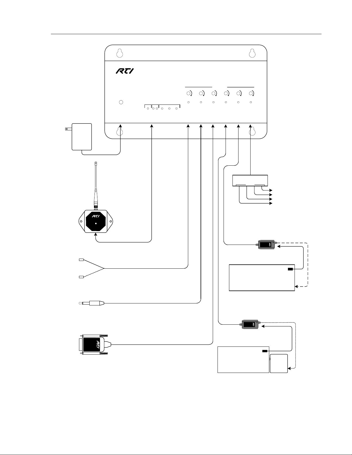
RP-6 CONNECTION OPTIONS
The following diagram shows just some of the common connection scenarios. There is a
virtually unlimited number of connection possibilities and devices that can be controlled.
Six (6) Multi-Purpose Output Ports
Removable Header for Connection
to IR Receivers, IR Keypad s, RTI RF
Receivers, & Contact Closures.
4
Page 11
Chapter 2. Introduction
Model RP-6
Remote Control Processor
STAT US
RELAYSIRPWR
123
+ + + + + +
IR Output Level
RP-6
Power
Supply
RM-433
SIGNAL
POWER EXPANSION
RF or IR Receivers
Single or Dual Emitters
SIGNAL IN
HIGH OUT
GROUND
CONTACT B
CONTACT A
+ 12V DC
PORT 1 PORT 2 PORT 3 PORT 4 PORT 5 PORT 6
CONTACT A
CONTACT A
CONTACT B
CONTACT B
Each IR output can drive up
to four emitters directly.
(more than four emitters requires
an amplified connecting block)
Signal Input
Connecti ng Block
Xantech® or compatible
Emitters
To Source Equipment,
Surround Processors,
Lighting System s, Et c.
*
SPS-1
Video
*
IR Emitter
Video equipment with
Composite output
CM-232
Direct to Back Panel IR Port
CM-232 Communication Module
Optional Accessories sold separately
*
Voltage
VPS-1
*
IR Emitter
*
Source equipment
with a switched outlet
Wall Mount
Power
Supply
5
Page 12

RP-6 Remote Control Processor
RP-6 REMOVABLE HEADER TERMINAL DESCRIPTION
TERMINAL NAME DESCRIPTION
Positive power supply connection. It is
internally tied to the Power jack. This can be
+12VDC
GROUND
SIGNAL IN
used to power external IR or RF receivers, or
fed into one side of a relay to create a trigger
Common ground connection. Use this ground
reference for any device that is connected to
the +12VDC, GROUND, SIGNAL IN, OR
Input connection for system trigger codes.
This should be connected to a RTI RF receiver
or industry standard IR repeater system. The
signal voltage can be from 3VDC – 12VDC.
voltage output.
HIGH OUT terminals.
High current (200mA) IR output connection.
HIGH OUT
CONTACT A
CONTACT B
This can be used to power up to 10 infrared
mini-emitters, an IR blaster, or extending IR
control over a long distance (1000 ft. max).
Relay contact connection. Each of the three
relays has two contact terminals (A & B). The
relays can each switch loads up to 3A/30VDC
and are software selectable to be either
normally open or normally closed.
Relay contact connection. Each of the three
relays has two contact terminals (A & B). The
relays can each switch loads up to 3A/30VDC
and are software selectable to be either
normally open or normally closed.
6
Page 13

Chapter 3. Installation
Chapter 3. Installation
INSTALLATION LOCATION
For best results install the RP-6 at least three (3) feet away from video monitors and
other sources of strong electro-magnetic energy.
IRF-6
Model RP-6
Remote Control Processor
STATUS
POWER EXPANSION
GROUND
+ 12V DC
RELAYSIRPWR
123
CONTACT B
CONTACT A
SIGNAL IN
HIGH OUT
+ + + + + +
CONTACT A
CONTACT A
CONTACT B
CONTACT B
PORT 1
PORT 2 PORT 3
IR Output Level
PORT 5 PORT 6
PORT 4
3 Feet 3 Feet
3 Feet 3 Feet
IRF-6
Model RP-6
Remote Control Processor
STATUS
POWER EXPANSION
+ 12V DC
GROUND
SIGNAL IN
HIGH OUT
123
CONTACT A
RELAYSIRPWR
CONTACT B
CONTACT A
CONTACT A
CONTACT B
CONTACT B
IR Output Level
+ + + + + +
PORT 2 PORT 3
PORT 1
PORT 4
PORT 5 PORT 6
7
Page 14

RP-6 Remote Control Processor
MOUNTING
The RP-6 can be mounted on either a shelf or a wall (see Appendix A for mounting hole
details). Since the IR output ports can drive up to 1000 feet of wire, and the optional
Power Sensor and Communication Modules can be extended, the RP-6 does not need to
be mounted near the equipment being controlled.
CONNECTING THE AC ADAPTER
The included AC adapter should be connected to the POWER jack on th e RP-6. The
power LED will turn-on and the output LEDs will toggle on and off in sequence to
confirm that the unit is running properly.
Use only the supplied AC adapter to power the RP-6. Using a different power supply
could result in damage to the RP-6 or poor performance.
CONNECTING IR EMITTERS TO OUTPUT PORTS
The multi-purpose output ports on the RP-6 are compatible with industry standard
infrared emitters and infrared repeating systems. Each output port is capable of driving
up to four infrared emitters directly. More than four infrared emitters requires an
amplified connecting block. A connecting block can be wired up to 1000 feet away from
the RP-6 using #22 AWG (minimum) wire.
For the most reliable connection to the RP-6 output ports, make sure to use the
included IR emitter adapter cables.
CONNECTING POWER SENSOR MO DULES
The multi-purpose output ports on the RP-6 are compatible with RTI power sensing
modules (e.g. VPS-1 and SPS-1). Follow the guide included with the modules for
installation instructions, and follow the instructions in the TheaterTouch Designer™
software guide for programming details.
CONNECTING COMMUNICATION MODULES
The multi-purpose output ports on the RP-6 are compatible with RTI communication
modules (e.g. CM-232). Follow the guide included with the modules for installation
instructions, and follow the instructions in the TheaterTouch Designer™ software guide
for programming details.
CONNECTING INFRARED RECEIVERS
The RP-6 is compatible with industry standard IR receivers, repeater systems, and
keypads. Connect the SIGNAL IN, GROUND, and +12VDC (if power is needed)
terminals to the signal out, ground, and power (if needed) terminals of the desired
8
Page 15

Chapter 3. Installation
device. The RP-6 provides a 1K ohm load between SIGNAL IN and GROUND. In some
cases this load may need to be increased by attaching a smaller value resistor across the
two terminals.
If the RP-6 sees an incoming system trigger code with a matching zone ID, it will
execute the command or macro associated with that code. The RP-6 can be programmed
to either block or pass miscellaneous IR data through it’s output ports.
CONNECTING RF RECEIVERS
The RP-6 is compatible with RTI RF receiver modules (e.g. RM-433). Follow the guide
included with the modules for installation instructions.
CONNECTING THE INFRARED HIGH OUT
The RP-6 is compatible with industry standard IR connecting blocks. Connect the HIGH
OUT and GROUND terminals to the signal input and ground terminals on the
connecting block. This is useful if you have many devices to control, or you want to
extend control into other rooms.
This output has short circuit protection, but does not provide a series resistor for current
limiting. It should not be connected directly to IR emitters.
CONNECTING THE RELAYS
The three relays in the RP-6 can provide contact closure or switching control for loads
up to 3A/30VDC each. All three relays are Normally Open when not energized, but
they can be programmed to behave Normally Closed as long as power is applied to the
RP-6.
For contact closure control, simply connect the A and B contact terminals of a relay to
the desired device.
To use a relay as a voltage trigger, connect the positive side of a power supply to
CONTACT A, and connect CONTACT B and the ground side of the power supply to
the desired device. If the desired trigger voltage is +12VDC, it can be sourced directly
from the RP-6.
9
Page 16

RP-6 Remote Control Processor
10
Page 17

Chapter 4. Operation
Chapter 4. Operation
ADJUSTING IR OUTPUT GAIN
The IR output gain can be separately adjusted for each of the six output ports. The RP-6
is shipped with the IR gain set to the optimum level for most equipment, and it should
only need to be adjusted if the attached equipment is not responding reliably.
If adjustment is needed use the included screwdriver to rotate the IR output
clockwise for higher output power, or counter-clockwise for lower output power.
STATUS LED
The status LED will illuminate Green if a valid system trigger code is detected. The LED
will stay on while the RP-6 is busy processing the action associated with the trigger
code.
The status LED will flicker Green if an invalid system trigger code is detected. A trigger
code is invalid if there is no action associated with it (i.e. the RP-6 programming does
not match the programming in the device that is transmitting the trigger code), or if the
system zone code does not match.
POT
The status LED will illuminate Red if the RP-6 does not contain a valid program.
The status LED will also illuminate Green to indicate an active USB connection. A
communication problem is indicated if the status LED is illuminated red while the USB
cable is attached to a PC.
PROGRAMMING THE RP-6
The RP-6 must be programmed to operate. All programming is done using RTI’s
TheaterTouch Designer™ software and is downloaded using the USB port.
Important Note: The RP-6 will not respond to trigger codes or execute
commands while the USB cable is attached to a PC. You must detach the
RP-6 USB port from your PC for normal operation.
The software allows you to create actions (e.g. commands and macros) that are
associated with button presses on one or more RTI remote controls. The software
transparently creates all of the system trigger codes, and generates the correct download
for every device in the system. Unless you implement some of the software’s advanced
features, programming a system that uses an RP-6 is just as easy as programming one
that doesn’t.
11
Page 18

RP-6 Remote Control Processor
SETTING THE ZONE CODE
If the RP-6 is installed in close proximity to others, the system Zone Code can be
changed in the TheaterTouch™ Designer software. This allows up to 256 separate control
systems to operate in the same general area such as multi dwelling units or homes with
more than one media system.
THE EXPANSION PORT
The expansion port provides two-way serial communication for use with a RF
transceiver, Ethernet bridge, etc.
12
Page 19

Chapter 5. Troubleshooting
Chapter 5. Troubleshooting
If you are having problems with your RP-6 Remote Control Processor, please read
these troubleshooting tips and frequently asked questions before contacting
technical support.
If you continue to have problems, see Chapter 6 for more information on contacting
RTI technical support.
RP-6 DOES NOT FUNCTION PROPERLY
! Verify that the USB cable is removed from either the RP-6 or the PC. The RP-6
will not function normally while there is an active USB connection with a PC.
! Verify the RP-6 is receiving a signal from an attached IR or RF receiver. The
Signal In LED should flash when a signal is present.
! Make sure the original factory power supply is plugged into a known good, non-
switched outlet and the connector is seated properly on the RP-6. The Power
LED should be turned on.
! Verify the button on the remote is programmed to output system trigger codes.
Also verify that the programmed output method (IR or RF) matches the receiver
being used.
! Try re-programming both the RP-6 and the remote control to make sure the
programming is up-to-date (i.e.“in sync”) in each of them.
! Make sure the IR or RF receiver wire is attached to the RP-6 properly.
! Make sure the IR or RF receiver is mounted away from strong electro-magnetic
energy sources.
! Make sure you are using known good IR emitters, and they are attached to the
correct location on the device being controlled. Also verify that an IR emitter
adapter cable is being used between the RP-6 and the IR emitter plug.
POWER SENSOR MODULES ARE NOT FUNCTIONING
! Verify that the modules are programmed to use the correct output port and the
proper conditional statement is used in the TheaterTouch Designer™ software.
! Make sure you are using a known good IR emitter, and it is attached to the
correct location on the device being controlled.
RP-6 USB PROGRAMMING PORT DOES NOT WORK
! Verify that your PC is using Windows 2000
®
Designer™ software requires a USB device driver that may not be installed on
®
earlier versions of Windows
.
or higher. The TheaterTouch
13
Page 20

RP-6 Remote Control Processor
14
Page 21

Chapter 6. Service and Support
Chapter 6. Service and Support
For news about the latest updates, new product information, and new accessories,
please visit our web site at:
www.rticorp.com
CONTACTING RTI
For general info, you can contact RTI at:
Tel. (952) 253-3100
Fax (952) 253-3131
info@rticorp.com
RTI TECHNICAL SUPPORT
At RTI, customer service and satisfaction is an utmost priority. If you are
encountering any problems or have a question about your RTI product, please
contact RTI Technical Support for assistance.
RTI provides technical support by telephone, fax or e-mail. For the highest quality
service, please have the following information ready, or provide it in your fax or
e-mail.
♦ Your Name
♦ Company Name
♦ Telephone Number
♦ E-mail Address
♦ Product model and serial number (if applicable)
If you are having a problem with hardware, please note the equipment in your
system, a description of the problem, and any troubleshooting you have already
tried.
If you are having a problem with software, please note what version you have
installed, the operating system on your PC, a description of the problem, and any
troubleshooting you have already tried.
15
Page 22

RP-6 Remote Control Processor
If you are calling about a software or programming question or problem, please be
at you computer when you place your call. This will considerably speed up the
troubleshooting process.
For technical support or assistance with your RP-6, software, or accessories, contact
RTI at:
(952) 253-3137
support@rticorp.com
www.rticorp.com/support
For questions regarding service or repair of your RP-6, contact RTI at:
(952) 253-3136
service@rticorp.com
www.rticorp.com/service
Please do not return products to RTI without return authorization.
SHIPMENT OF RP-6 FOR SERVICE
RTI will pay all labor and material expenses for all repairs covered by this product’s
warranty. If necessary repairs are not covered by warranty, or if a unit is examined
which is not in need of repair, you may be charged for the repairs or examination.
If it is necessary to ship the RP-6 Remote Control Processor for service:
♦ Please pack it securely (we suggest that it be insured).
♦ Do not include accessories such as power cords or manuals unless
instructed to do so.
You must pay any shipping charges incurred in getting your RP-6 Remote Control
Processor to RTI. RTI will pay reasonable return shipping charges via a carrier of our
choice to any destination within the United States if the repairs are covered under
warranty.
16
A copy of the original dated sales receipt must be provided whenever warranty
service is required. You will need this receipt to establish the date of purchase.
Page 23

Chapter 7. Specifications
Chapter 7. Specifications
Power Supply: +12V DC , 1Amp
Number of Output Ports: Six (6) Multi-Purpose ports
One (1) High Power IR port
Multi-Purpose Output Ports: Custom 3.5mm 4-conductor jacks are
designed for RTI Modules as well as
industry standard IR emitters.
IR Output Drive: 100mA maximum (per port, adjustable)
200mA maximum (high IR output port)
Infrared Transmission Bandwidth: 15kHz - 460kHz
Infrared Input: Compatible with industry-standard
repeaters and receiving systems.
Relays: Three (3) Relays – 3 Amps
Mounting: Wall-Mount or Free Standing
Dimensions: 9.3” (236mm) x 5.3” (135mm) x 1.5” (38mm)
Weight: 1 lb. 3 oz. (543g)
All specifications are subject to change without notice.
@
30 VDC each
17
Page 24

RP-6 Remote Control Processor
18
Page 25

Appendix A. Mounting Hole Pattern
Appendix A. Mounting Hole Pattern
4-3/8 in (111 mm)
IR Output Level
+ + + + + +
PORT 1 PORT 2 PORT 3 PORT 4 PORT 5 PORT 6
CONTACT B
CONTACT A
CONTACT B
RELAYSIRPWR
123
Remote Control Processo r
Model RP-6
STATUS
CONTACT A
CONTACT B
CONTACT A
HIGH OUT
SIGNAL IN
GROUND
+ 12V DC
POWER EXPANSION
7-1/2 in (190 mm)
19
Page 26

RP-6 Remote Control Processor
20
Page 27

INDEX
INDEX
—C—
Communication Modules, Connecting, 8
Connection Options, 4
Contacting RTI
General, 15
Service, 16
Technical Support, 15
Contents, 2
—E—
Ethernet, 12
Expansion Port, 12
—F—
FCC Notice, ii
Features, RP-6, 3
—G—
Ground, Terminal description, 6
—H—
High Out. See IR
High Out, Terminal description, 6
—P—
Power Sensing
Modules, connecting, 8
Power, Terminal description, 6
Programming, 11
—R—
Reference Picture, 4
Relay Contact A, Terminal description, 6
Relay Contact B, Terminal description, 6
Relays, Connecting, 9
RF Receivers, Connecting, 9
RS-232
Baud Rate Range, 3
—S—
Safety suggestions, iii
Signal In, Terminal description, 6
Specifications, 17
—T—
Technical Support. See Contacting RTI
Troubleshooting, 13
—I—
Impotant notes, 1
Installation, 7
IR
Emitters, Connecting, 8
High Out, 9
Output Frequency Range, 3
Output Gain, 11
Receivers, Connecting, 8
—M—
Mounting, 8
—U—
Unpacking, 2
—W—
Warranty, iv
—Z—
Zone Code, Setting of, 12
21
Page 28

22
Page 29

23
Page 30

It’s Under Control ®
Remote Technologies Incorporated
Remote Technologies Incorporated
Remote Technologies IncorporatedRemote Technologies Incorporated
18681 Lake Dr ive East
Chanhassen , MN 55317
Tel: 952-253-3100
Fax: 952-523-3131
www.rticorp.com
©
2004 Remote Technologies Inc. All rights reserved. Printed in USA.
IR-PRO
Professional Inf r ar ed C ode Capt ur e S yst em
 Loading...