

Page 1

1
It’s Under Control
®
RK3-V
In-Wall Controller
It’s Under Control
®
Installation and Operation Guide
70-210054-19 V 1.0
Page 2

In-Wall Controller
RK3-V
2
Copyright © 2009
Remote Technologies Incorporated
All rights reserved.
Page 3

3
It’s Under Control
®
This equipment has been tested and found to comply with the limits for a
Class B digital device, pursuant to Part 15 of the FCC Rules. These limits
are designed to provide reasonable protection against harmful interference
in a residential installation.
This equipment generates, uses, and can radiate radio frequency energy
and, if not installed and used in accordance with the instructions, may
cause harmful interference to radio communications. However, there is no
guarantee that interference will not occur in a particular installation.
If this equipment does cause harmful interference to radio or television
reception, which can be determined by turning the equipment off and on,
the user is encouraged to try to correct the interference by one or more of
the following measures:
Reorient or relocate the receiving antenna.
Increase the separation between the equipment and the receiver.
Connect the equipment into an outlet on a circuit different from that to
which the receiver is connected.
Consult the dealer or an experienced radio/TV technician for help.
This device complies with Part 15 of the FCC Rules. Operation is subject to
the following two conditions:
1. This device may not cause harmful interference.
2. This device must accept any interference received including
interference that may cause undesired operation.
FEDERAL COMMUNICATIONS COMMISSION NOTICE
DECLARATION OF CONFORMITY (DOC)
The Declaration of Conformity for this product can be found on the RTI
website at: www.rticorp.com/declaration
117 612 914
Page 4

In-Wall Controller
RK3-V
4
Read Instructions. Read all safety and operating instructions before
operating the unit.
Retain Instructions. Keep the safety and operating instructions for future
reference.
Heed Warnings. Adhere to all warnings on the unit and in the operating
instructions.
Follow Instructions. Follow operating instructions and instructions for use.
Heat. Keep the unit away from heat sources such as radiators, heat
registers, stoves, etc., including ampliers that produce heat.
Power Sources. Connect the unit only to a power supply of the type
described in the operating instructions, or as marked on the unit.
Power Cord Protection. Route power supply cords so that they are not
likely to be walked on or pinched by items placed on or against them,
paying particular attention to the cord plugs at power receptacles and at the
point at which they exit from the unit.
Water and Moisture. Do not use the unit near water—for example, near a
sink, in a wet basement, near a swimming pool, near an open window, etc.
Object and Liquid Entry. Do not allow objects to fall or liquids to be spilled
into the enclosure through openings.
Cleaning. The unit should be cleaned only as recommended in the
operating guide.
Servicing. Do not attempt any service beyond that described in the
operating instructions. Refer all other service needs to qualied service
personnel.
Damage Requiring Service. The unit should be serviced by qualied
service personnel when:
The power supply cord or the plug has been damaged.
Objects have fallen or liquid has been spilled into the unit.
The unit does not appear to operate normally or exhibits a marked
change in performance.
WARNING!
TO REDUCE THE RISK OF FIRE OR ELECTRIC SHOCK,
DO NOT EXPOSE THE UNIT TO RAIN OR MOISTURE.
SAFETY SUGGESTIONS
Page 5

5
It’s Under Control
®
Remote Technologies Incorporated warrants its products for a period of
one (1) year (90 days only for included battery packs) from the date of
purchase from Remote Technologies Incorporated or an authorized Remote
Technologies Incorporated distributor.
This warranty may be enforced by the original purchaser and subsequent
owners during the warranty period, so long as the original dated sales receipt
or other proof of warranty coverage is presented when warranty service is
required.
Except as specied below, this warranty covers all defects in material and
workmanship in this product. The following are not covered by the warranty:
Damage resulting from:
1. Accident, misuse, abuse, or neglect.
2. Failure to follow instructions contained in this Guide.
3. Repair or attempted repair by anyone other than Remote Technologies
Incorporated.
4. Failure to perform recommended periodic maintenance.
5. Causes other than product defects, including lack of skill, competence or
experience of user.
6. Shipment of this product (claims must be made to the carrier).
7. Being altered or which the serial number has been defaced, modied or
removed.
Remote Technologies Incorporated is not liable for any damages caused by its
products or for its failure of its products to perform, including any lost prots,
lost savings, incidental damages, or consequential damages.
Remote Technologies Incorporated is not liable for damages based upon
inconvenience, loss of use of the product, loss of time, interrupted operation,
commercial loss, any claim made by a third party or made by you for a third
party.
Remote Technologies Incorporated’s liability for any defective product is
limited to repair or replacement of the product, at our option.
If your RK3-V In-Wall Controller needs service, please contact Remote
Technologies Incorporated by telephone, fax or E-mail for return information.
Please do not return products to Remote Technologies Incorporated
without return authorization.
LIMITED WARRANTY
Page 6

In-Wall Controller
RK3-V
6
DISCLAIMER
All rights are reserved. No part of this document may be photocopied,
reproduced, or translated without the prior written notice of Remote
Technologies Incorporated.
The information contained in this document is subject to change without
notice. Remote Technologies Incorporated shall not be liable for errors or
omissions contained herein or for consequential damages in connection with
the furnishing, performance, or use of this guide.
Microsoft, Windows, Windows XP and Windows Vista are registered
trademarks of Microsoft Corporation in the United States and other countries.
RK3-V, Integration Designer, and the RTI logo are registered trademarks of
Remote Technologies Incorporated.
Other brands and their products are trademarks or registered trademarks of
their respective holders.
Page 7

7
It’s Under Control
®
TABLE OF CONTENTS
Federal Communications Commission Notice .............. 3
Safety Suggestions ..................................................... 4
Limited Warranty ...................................................... 5
Disclaimer .................................................................. 6
Contents ..................................................................... 7
Chapter 1 - Welcome .................................................. 9
Chapter 2 - Introduction ............................................ 11
Chapter 3 - Installation ............................................. 13
Chapter 4 - Operation ................................................ 17
Chapter 5 - Specications .......................................... 25
Chapter 6 - Troubleshooting ...................................... 27
Chapter 7 - Service and Support ................................ 29
Index ........................................................................ 31
Page 8

In-Wall Controller
RK3-V
8
Page 9

9
It’s Under Control
®
Thank you for purchasing the RK3-V In-Wall Controller. The RK3-V provides
elegant and intuitive control of today’s entertainment, environment and
security systems. Representing the second generation of the award-winning
RK3 In-wall Controller, the RK3-V is capable of displaying text and graphics
with incredibly rich and vivid detail with a new full VGA display - 4 times
the resolution of it’s renowned predecessor. Designed for ush-mount
installations in walls or cabinets the RK3-V is the only compact in-wall
touchpanel that provides both direct infrared control and 10/100Base-T
Ethernet for displaying digital video (motion JPEG) and web pages.
The RK3-V In-wall Controller blends into any room. The perfect balance
between display size and resolution, a 3.5 inch LCD is small enough to t
in any decor, yet it provides the necessary resolution for displaying custom
graphics, web pages and CD cover artwork. In addition, the RK3-V is unique
because its graphical user interface (GUI) and programming are completely
customizable making it easy to provide simple and intuitive control for the
end-user.
The RK3-V can be used as a stand-alone device or as a part of an
expandable central control system. It can directly control almost any audio/
video component or lighting system up to 1000 feet away using its infrared
output port. When used with the available RTI accessory devices, the RK3-V
is capable of infrared routing, relay control, power sensing, and two-way
RS-232 communications for advanced control. In any situation, from simple
to complex, the RK3-V provides the perfect level of control.
COMPATIBILITY
The RK3-V and Integration Designer® software are compatible with infrared
(IR) commands with carrier frequencies between 15kHz and 460kHz, as
well as those commands that do not use a carrier. This covers virtually all
of the remotes that exist to date.
SOFTWARE REQUIREMENTS
The recommended minimum system requirements needed to run the
Integration Designer® software are as follows:
Windows XP®, Windows Vista® or later version of Microsoft operating
system.
CHAPTER 1 | WELCOME
Page 10

In-Wall Controller
RK3-V
10
CHAPTER 1 | WELCOME
UNPACKING AND INSPECTION
After unpacking your new RK3-V In-Wall Controller, save all of the packing
materials in case you ever have to ship the unit.
Thoroughly inspect the RK3-V and packing materials for signs of damage.
Report any damage to the carrier immediately. Report any equipment
malfunctions to Remote Technologies Incorporated or an authorized
Remote Technologies Incorporated distributor.
PRODUCT CONTENTS
Contents within the box include the following items:
One (1) RK3-V In-Wall Controller
One (1) Cut-out template.
Two (2) Spare retrot mounting wings.
One (1) Operation and Installation guide.
Page 11

11
It’s Under Control
®
CHAPTER 2 | INTRODUCTION
FEATURES
The RK3-V provides superior quality and reliability as well as these features:
Stylish low-prole faceplate bezel available in many colors and styles.
Available with multiple faceplate and button color options.
Full VGA resolution LCD to display custom buttons, text and graphics.
Integrated high-resolution touchscreen.
Integrated 10/100Base-T Ethernet port with Power-over-Ethernet.
Plasma friendly infrared receiver for command pass-through.
IR output port drives up to 1,000 feet of wire.
Two power status input ports.
Powerful 32-bit, 400MHz XScale processor.
512MByte of Flash Memory.
Integrated mounting wings for easy installation.
Nine assignable/programmable keys.
Completely customizable and programmable.
Non-volatile Flash Memory stores your program even when power is
lost.
Field upgradable rmware.
USB and Ethernet programming.
IMPORTANT NOTES
Please read these important notes about the RK3-V:
The RK3-V should be placed in an area where it is around normal room
temperature (between 60° F to 90° F). If the temperature is too hot,
the display appears dim. If the temperature is too cold, the display
appears dark and may respond slowly.
Avoid installing the RK3-V in a location where it can come in contact
with direct sunlight.
Do not install the RK3-V directly adjacent to thermostats. Heat
generated by the RK3-V may effect temperature measurement.
Do not use sharp objects on the touchscreen. It is designed to operate
with a touch of your nger.
Do not let the RK3-V get wet. It should not be handled with wet hands
or placed in an area where it could get wet.
Do not subject the RK3-V to smoke, dust, or vibrations. The display
may be damaged from excessive shock or vibration.
Only use the power supply that is specied for the RK3-V. Using the
wrong type of power supply may result in damage.
Do not disassemble the unit. Service of the RK3-V should be performed
by authorized personnel only.
Page 12
In-Wall Controller
RK3-V
12
CHAPTER 2 | INTRODUCTION
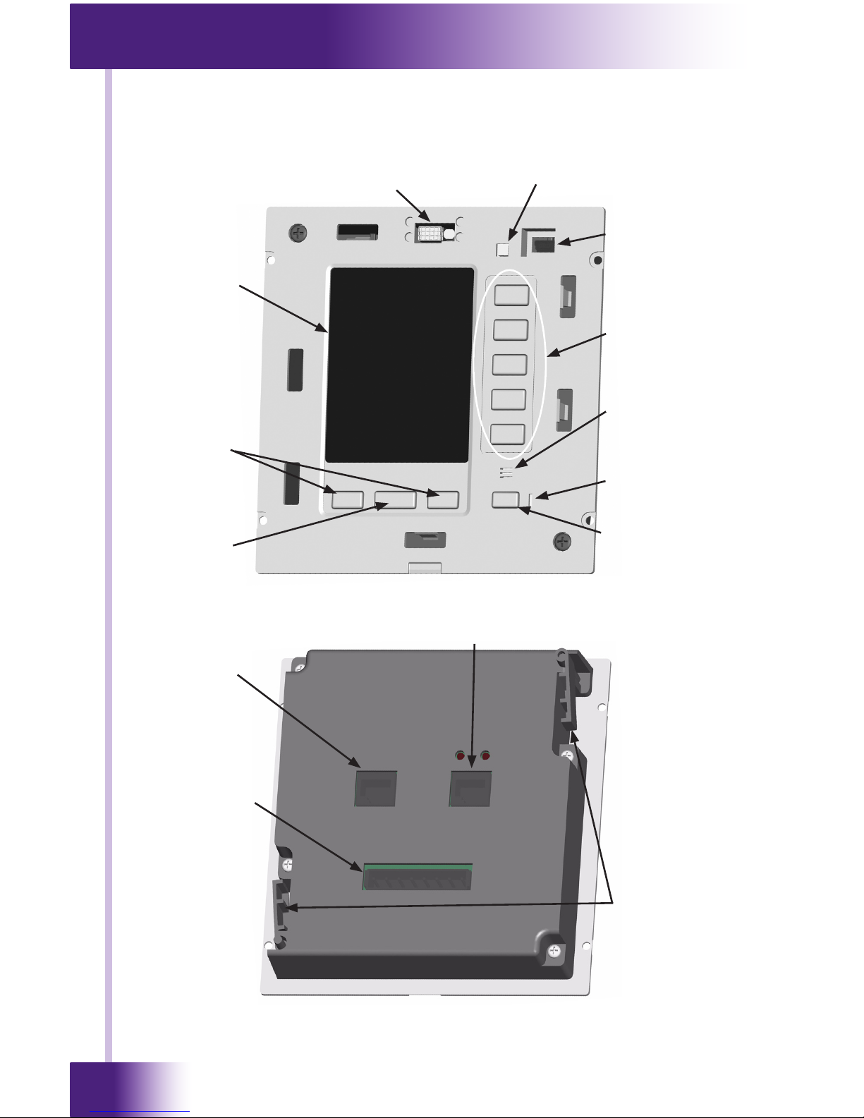
REMOTE REFERENCE
Front
Plasma Friendly Infrared Sensor
and Ambient Light Sensor
Touchpanel
LCD Display
Page Scroll
Buttons
Power Button
Power LED
Mono Speaker
Function
Buttons
USB Programming
Port
Reset Button
Home Page
Button
Back
Ethernet Port
Control Port
Removable
Terminal Block
Integrated
Mounting Wings
Page 13
13
It’s Under Control
®
CHAPTER 3 | INSTALLATION
The RK3-V is designed for ush-mount installations in walls or cabinets. It
requires an available mounting depth of 2.5 inches (63mm) from the front
surface of the wall. There are numerous options for mounting and wiring
the RK3-V.
Note: Make sure to use the included cardboard cut-out template to create
the correct size opening in the wall.
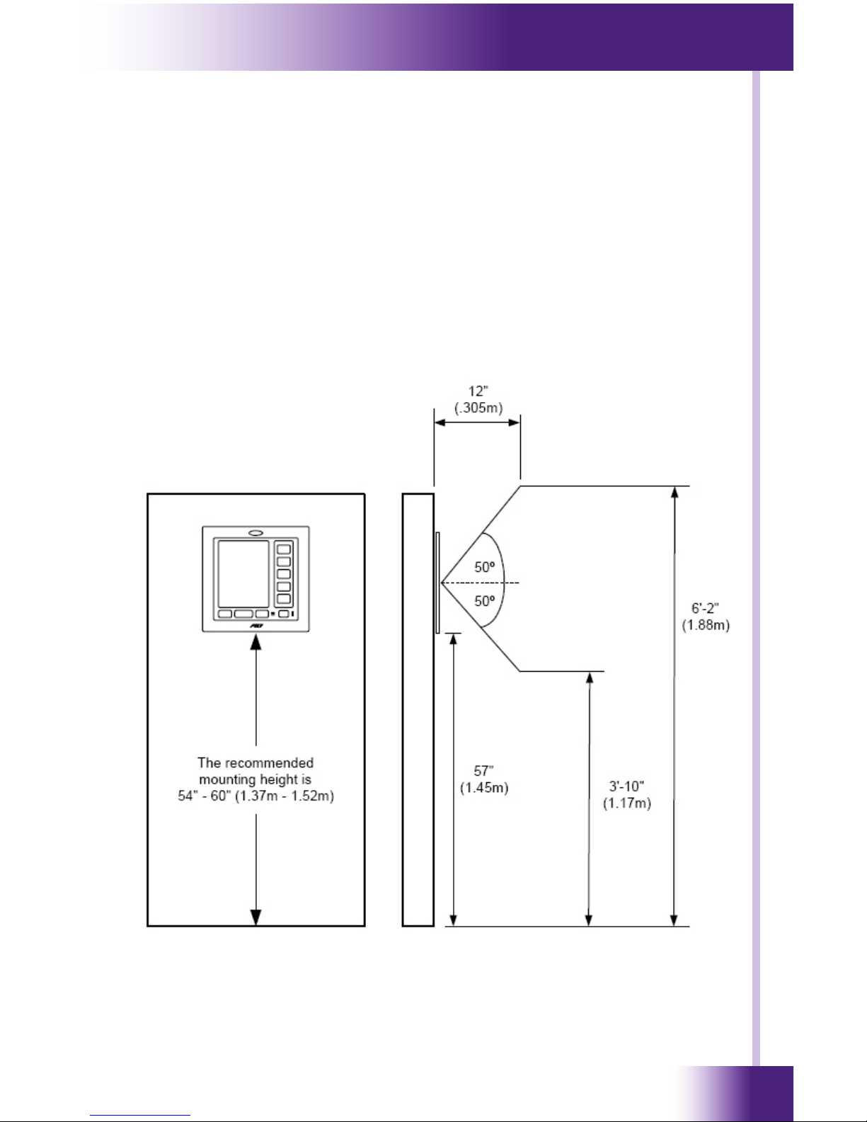
MOUNTING HEIGHT
The recommended mounting height for the RK3-V is between 54” (1.37m)
and 60” (1.52m) from the bottom of the faceplate.
RK3-V side view: Viewing angle at 57”
Page 14

In-Wall Controller
RK3-V
14
CHAPTER 3 | INSTALLATION
Power
Supply
Power
Supply
ZRP-6 Remote Control Processor
Ground
Ground
Infrared
+9 to +16 VDC
+9 to +16 VDC
Infrared
RS-485 RS-485+
Pin 8
Pin 7
Pin 6
Pin 5
Pin 4
Pin 3
Pin 2
Pin 1
CB-8 Connecting Block
RTI Connecting
Block
To IR receivers or
AV equipment,
lighting controls, etc.
20 AWG (min.)
wire or full
Cat-5 pairs
Ground
Infrared
Power
Cat-5 cable
Control System Operation
Stand-Alone Operation
Cat-5 cable
LAN
Page 15

15
It’s Under Control
®
TERMINALS
+16VDC
Positive power supply connection. This should be connected to a
9VDC-16VDC.
GND
Common ground connection. Use this ground reference for any device
that is connected to any of the other pins on the connector.
IR DATA
High current (200mA) IR output connection. This can be used to power
up to 10 infrared mini emitters or an IR blaster, delivering IR trigger
codes to a control processor, or extending IR control over a long
distance (1000 ft. max).
PWR STATUS
Voltage power sensing input connection. This can be connected to
a trigger output or switched outlet (using a small wall-mount power
supply) on A/V equipment, current sensors, light sensors, etc. The ON
state sense voltage is 3VDC – 20VDC. The OFF state sense voltage is
0VDC - 2VDC.
GND
Common ground connection. Use this ground reference for any device
that is connected to any of the other pins on the connector.
RELAY CTRL
Voltage trigger output. This can be used to control speaker relays,
screens, window coverings, etc. The output can supply up to 100mA
and has a voltage equal to the input supply.
AUX STATUS
Voltage power sensing input connection. This can be connected to
a trigger output or switched outlet (using a small wall-mount power
supply) on A/V equipment, current sensors, light sensors, etc. The ON
state sense voltage is 3VDC – 20VDC. The OFF state sense voltage is
0VDC - 2VDC.
TRIG OUT
Voltage trigger output. This can be used to control speaker relays,
screens, window coverings, etc. The output can supply up to 100mA
and has a voltage equal to the input supply.
CHAPTER 3 | INSTALLATION
Page 16

In-Wall Controller
RK3-V
16
CHAPTER 3 | INSTALLATION
MOUNTING OPTIONS
The RK3-V has integrated mounting wings for retrot installation in new
or existing construction. Additionally, the RK3-V can be directly attached
to certain walls (wood, etc.) using screws. An optional drywall rough-in
bracket (RTI part #: 40-210294-22) and preconstruction back box
(RTI part #: 30-210153-15) is available for conveniently locating the
RK3-V in new construction installations.
WIRING CONNECTION OPTIONS
The RK3-V can be wired either from the Control Port or the Removable
Terminal Block. A minimum of 3-conductor wire is required for basic
operation (+16VDC, GND, and IR DATA). CAT5 cable can be used to
power the RK3-V up to 1000 feet (300m) if a full wire pair is used for both
+16VDC and GND. For longer distances use the following size of unshielded
multi-conductor cable:
Wire Size Distance
20 AWG 1300’ (400m)
18 AWG 2000’ (600m)
NOTE: The IR Data connection does not need to be connected if the RK3-V
will be using an Ethernet connection for control.
Page 17

17
It’s Under Control
®
CHAPTER 4 | OPERATION
GETTING STARTED
The RK3-V is turned-on by simply applying power to it.
There are two power supply options which are sold separately:
Single Unit Power Supply (PS-16)
16VDC, 1.6Amp
Provides power for up to four RK3-V’s
Part Number: 40-210285-22
CB-8 Connecting Block
Includes 12VDC, 4.0Amp power supply
Provides power for up to twelve RK3-V’s
Provides a convenient connection hub
Part Number: 10-210205-11
After power is applied, the RK3-V will take approximately ten seconds to
load the operating system, the application software, and the user program.
This long delay only occurs from a power down state. During normal use
the RK3-V turns-on instantly from its sleep mode.
After powering down, the RK3-V is activated by touching any area of the
touchpanel display, or any hard button.
Page 18

In-Wall Controller
RK3-V
18
THE TOUCHSCREEN DISPLAY
The RK3-V touchscreen display is organized into a series of pages.
Normally each page contains objects (buttons, text, graphics, etc.) that
are related in some way. For instance, they may all display information
necessary for controlling a particular CD player.
By default, the RK3-V has one Home page—all other pages are normally
accessed from links on the Home page. In addition, any page can contain
buttons with a link to any other page.
Normally the Home page is used to display the names of the A/V sources
and other devices being controlled. The RK3-V will support a maximum of
200 pages including the Home page.
A representation of a programmed Home page is shown below:
CHAPTER 4 | OPERATION
Page 19

19
It’s Under Control
®
CHAPTER 4 | OPERATION
THE CONTROL PANEL PAGE
The Control Panel page can be displayed by pressing and holding the home
button while momentarily depressing the reset button. Continue to hold
the home button until the loading bar appears on the screen, then release
the home button.
You can also access the Control Panel page by assigning a “Control Panel”
page link to a button using the Integration Designer® software.
A representation of the Control Panel page is shown below:
To return to the user program, press Exit.
Page 20
In-Wall Controller
RK3-V
20
CHAPTER 4 | OPERATION
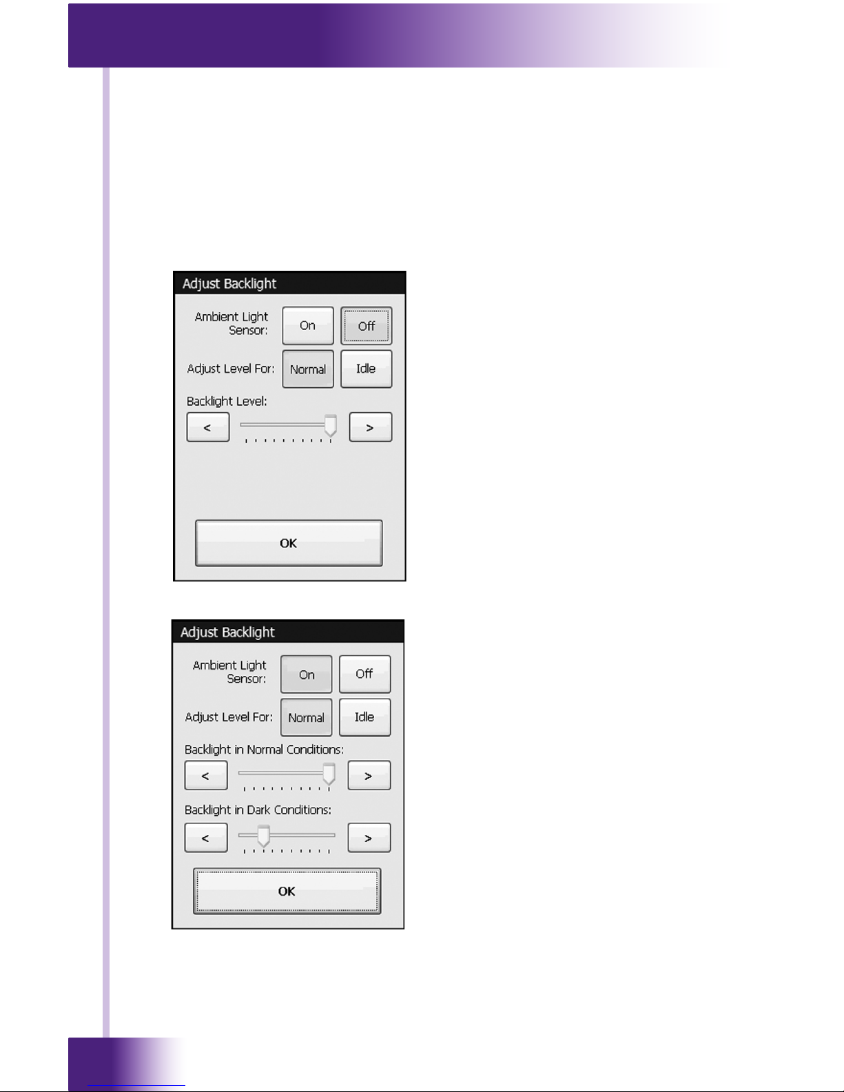
BACKLIGHT LEVEL
This button displays a window that allows you to adjust the backlight
brightness and enable/disable the Ambient Light Sensor.
If the light sensor is disabled, there is only one backlight level to adjust.
Press the left arrow or right arrow buttons to adjust. Press the OK button
when nished.
With the light sensor disabled,
the backlight brightness will
always stay at the same level
whenever the RK3-V is turnedon. The backlight level can,
however, be set differently
for the unit’s Normal and Idle
modes.
If the light sensor is enabled, there
are two backlight levels to adjust.
Press the left arrow or right arrow
buttons to adjust. Press the OK
button when nished.
With the light sensor enabled,
the backlight brightness will
automatically change between the
two levels, depending upon the
ambient lighting conditions. Also, the
backlight level can be set differently
for the unit’s Normal and Idle modes.
Page 21

21
It’s Under Control
®
CHAPTER 4 | OPERATION
TIME OUT
This button displays a window that allows you to adjust the amount of time
the unit stays awake after the last button press. The time is variable from
1 second to 120 seconds (the default is 10 seconds). Press the arrows to
the left or right of the Time Out setting to adjust the time.
If the backlight is programmed to turn off in idle mode, it is a good idea to
ignore the initial press of the touchscreen that turns the backlight on.
This will prevent unwanted button activations from occurring (since you
may not see what you’re pressing on the touchscreen when the backlight
is off). Select On to ignore the rst press, or Off to accept the rst press.
Press the OK button when nished.
Page 22

In-Wall Controller
RK3-V
22
CHAPTER 4 | OPERATION
IR RECEIVER
This button displays a window that allows you to enable or disable the
front panel IR Receiver. The IR Signal graphic turns red to indicate IR data
and/or noise being detected by the receiver. This helps to determine if you
should enable the receiver in a particular environment.
Press the OK button when nished.
SOUND
This button displays a window that allows you to adjust the volume of the
audible speaker. The speaker sound provides feedback that a button was
pressed. Press the arrows to the left or right to adjust the volume.
Press the OK button when nished.
There are six
discrete volume
settings. The
lowest setting
disables the
speaker.
Page 23

23
It’s Under Control
®
CHAPTER 4 | OPERATION
CALIBRATE TOUCHSCREEN
This button runs a routine that allows you to calibrate the touchscreen.
Since it normally should not be necessary to calibrate the touchscreen, this
routine is included as a precaution only.
Warning: Do not attempt to calibrate the touchscreen with your ngertip.
Proper calibration requires a stylus or other ne tip. Do not use metal
objects such as ball point pens or screwdrivers that can damage the
surface of the touchscreen.
Press the Calibrate button to continue.
Follow the directions on the display to complete the calibration process.
NETWORK INFORMATION
This button displays a window that allows you to view the Ethernet network
information. This is mainly for troubleshooting purposes.
Press the OK
button when
nished.
Page 24

In-Wall Controller
RK3-V
24
THE WEB BROWSER
The RK3-V includes Internet Explorer® for web browsing on the internet.
Although most website content is compatible with the RK3-V, please note
that plug-ins such as JAVA® and Flash®8 or higher, streaming video, and
persistent cookies are not supported.
A graphical representation of a keyboard will automatically popup on the
display whenever text entry is required. The keyboard can be dragged
around the display by using its title bar. It can be dismissed by touching
anywhere on the display that is outside of the keyboard.
CHAPTER 4 | OPERATION
Page 25
25
It’s Under Control
®
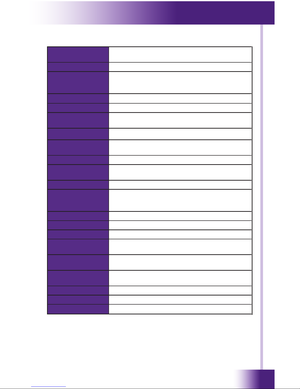
CHAPTER 5 | SPECIFICATIONS
Power +9VDC to +16VDC, .5A max or 802.3af Power-
over-Ethernet
Power Management Adjustable backlight brightness/power down time
Touchscreen Display High-brightness color TFT LCD, Full VGA (480x640
pixels) with 65K colors, integrated high-resolution
resistive touchscreen
Display Size 3.5 in (89mm) diagonal
Backlights White LED (Display), Blue/Amber LED (Keypad)
Infrared Output Port 200mA output, drives up to 1000 ft (300 m) of
wire
Ethernet Port 10/100Base-T with Power-over-Ethernet
Operating
Temperature
+32°F to +122°F (0°C to +50°C)
Operating Humidity 5% to 95% Non-condensing
Total System
Memory
512M Bytes Flash (non-volatile) memory
Device Capability Total number of devices is limited only by memory
Macro Capability Unlimited steps in a single macro
Total number of macros is limited only by memory
Macro capability on every button
Communications USB programming port
Enclosure High-impact molded ABS plastic, black
Front Plate High-impact molded ABS plastic, gray or black
Mounting Integrated mounting wings, or screws through
front bezel
Front Plate
Dimensions (H x W)
5 3/4 in (146mm) x 5 1/2 in (140mm)
Installation
Cut-Out (H x W)
5 1/8 in (130mm) x 4 3/4 in (120mm)
Total Depth in Wall 1/8 in (29mm) plus cables
Weight 10 oz (284 g)
Warranty One Year (Parts & Labor)
All specications subject to change without notice.
Page 26

In-Wall Controller
RK3-V
26
Page 27

27
It’s Under Control
®
If you are having problems with your RK3-V In-Wall Controller, please read
the information below before contacting technical support.
If you continue to have problems, see Chapter 6 for more information on
contacting RTI technical support.
DISPLAY IS DIM, BLANK OR UNREADABLE
Make sure the external power supply is properly secured to the RK3-V,
and it is functioning properly.
Try adjusting the backlight level from the Control Panel page (Refer to
Chapter 4 for more details).
By nature, the contrast of an LCD screen changes with temperature,
so if the display is cold it will appear dark and will return to normal as
it warms.
USB COMMUNICATION PROBLEMS
Verify that your PC is running Windows XP® or later.
Verify that the RK3-V USB driver was installed the rst time the RK3-V
was connected to your PC.
Verify that the RK3-V is present in the Device Manager within the
Windows® Control Panel.
Make sure you are using the programming cable that was supplied by
RTI and that both ends are connected securely.
Make sure the PC detects the presence of the RK3-V. If it doesn’t,
unplug the USB cable, wait for about ten seconds, and plug it in again.
If the download fails after some data has been transferred, try
resending the program.
IR CODE PROBLEMS
If you are using an IR repeater system, make sure it is working
correctly with the original OEM remote. If not, you will need to
troubleshoot the IR repeater system.
If you are still having problems, try adjusting the IR code “Minimum
Repeats” value in the Integration Designer® programming software.
If the IR code is executed inside a macro that contains multiple IR
codes, try inserting a small time delay before the problem code. If
there already is a delay, try increasing it.
CHAPTER 6 | TROUBLESHOOTING
Page 28

In-Wall Controller
RK3-V
28
Page 29

29
It’s Under Control
®
For news about the latest updates, new product information, and new
accessories, please visit our web site at:
www.rticorp.com
CONTACTING RTI
For general info, you can contact RTI at:
Tel. (952) 253-3100
Fax (952) 253-3131
info@rticorp.com
RTI TECHNICAL SUPPORT
At RTI, customer service and satisfaction is an utmost priority. If you are
encountering any problems or have a question about your RTI product,
please contact RTI Technical Support for assistance.
RTI provides technical support by telephone, fax or e-mail. For the highest
quality service, please have the following information ready, or provide it in
your fax or e-mail.
Your Name
Company Name
Telephone Number
E-mail Address
Product model and serial number (if applicable)
If you are having a problem with hardware, please note the equipment in
your system, a description of the problem, and any troubleshooting you
have already tried.
If you are having a problem with software, please note what version you
have installed, the operating system on your PC, a description of the
problem, and any troubleshooting you have already tried.
If you are calling about a software or programming question or problem,
please be at you computer when you place your call. This will considerably
speed up the troubleshooting process.
For technical support or assistance with your RK3-V, software, or
accessories, contact RTI at:
(952) 253-3137
support@rticorp.com
www.rticorp.com
For questions regarding service or repair of your RK3-V, contact RTI at:
(952) 253-3136
service@rticorp.com
www.rticorp.com
Please do not return products to RTI without return authorization.
CHAPTER 7 | SERVICE AND SUPPORT
Page 30

In-Wall Controller
RK3-V
30
CHAPTER 7 | SERVICE AND SUPPORT
Shipment of RK3-V for Service
RTI will pay all labor and material expenses for all repairs covered by this
product’s warranty. If necessary repairs are not covered by warranty, or if
a unit is examined which is not in need of repair, you may be charged for
the repairs or examination.
If it is necessary to ship the RK3-V In-Wall Controller for service:
Please pack it securely (we suggest that it be insured).
Do not include accessories such as power cords or manuals unless
instructed to do so.
You must pay any shipping charges incurred in getting your RK3-V InWall Controller to RTI. RTI will pay reasonable return shipping charges via
a carrier of our choice to any destination within the United States if the
repairs are covered under warranty.
A copy of the original dated sales receipt must be provided whenever
warranty service is required. You will need this receipt to establish the date
of purchase.
Page 31

31
It’s Under Control
®
INDEX
Contents ...........................................................................7
Features .......................................................................... 11
Federal Communications Commission Notice .......................... 3
Installation ...................................................................... 13
Introduction ..................................................................... 11
Cleaning ...................................................................... 11
Remote Reference ......................................................... 12
Limited Warranty/Disclaimer ................................................ 5
Operation ........................................................................ 17
Product Contents .............................................................. 10
Safety Suggestions ............................................................. 4
Service and Support ......................................................... 29
Contact RTI .................................................................. 29
Shipment for Service ..................................................... 30
Technical Support .......................................................... 29
Specications ................................................................... 25
Troubleshooting ................................................................ 27
Page 32

In-Wall Controller
RK3-V
32
Remote Technologies Incorporated
5775 12th Avenue East, Suite 180
Shakopee, MN 55379
Tel: 952-253-3100
Fax: 952-253-3131
www.rticorp.com
© 2009 Remote Technologies Inc. All rights reserved. Printed in Taiwan.
It’s Under Control
®
 Loading...