

Page 1
IR-PRO
Professional Infrared Code Capture System
IR-PRO
Professional Infrared Code Capture System
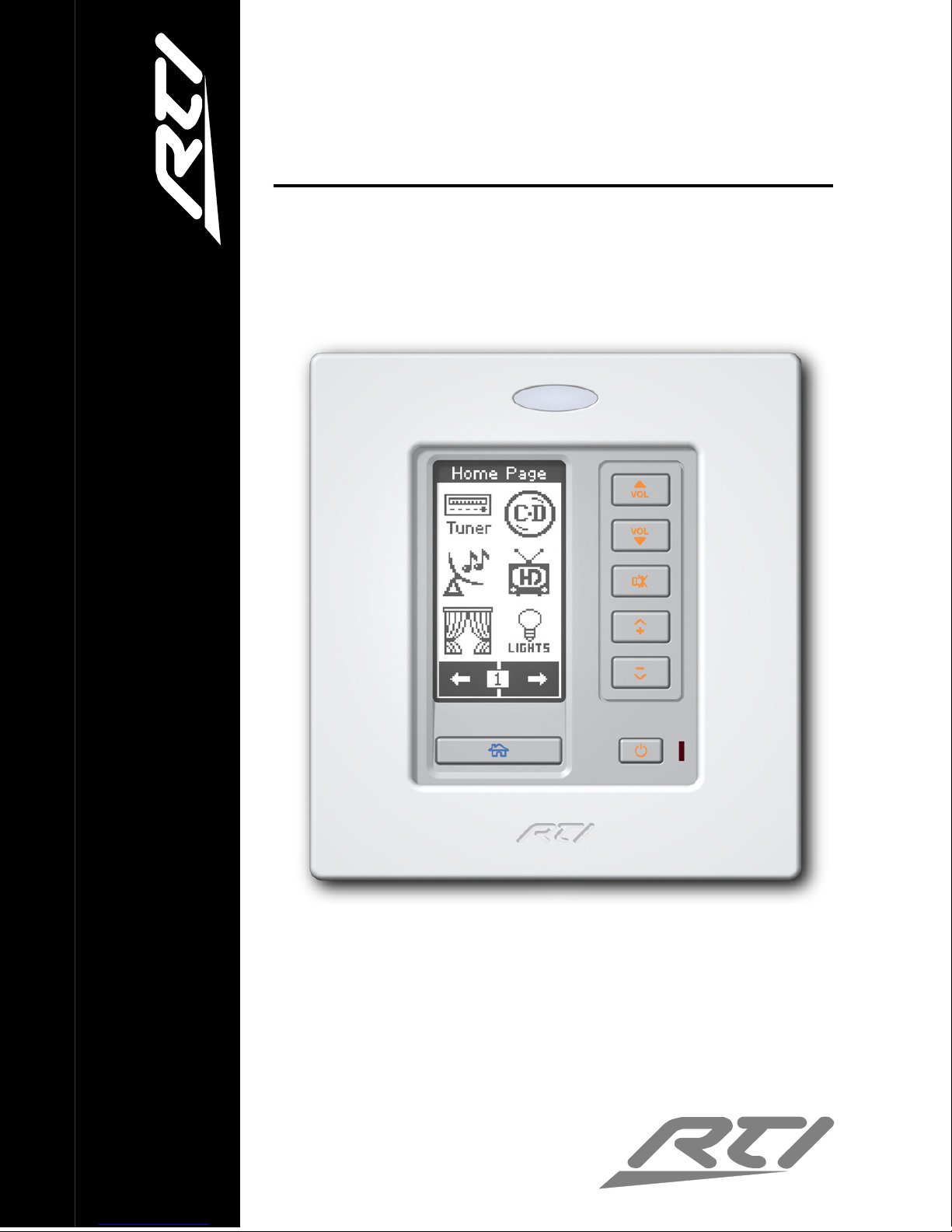
RK2
In-Wall Universal Controller
RK2
Operation & Installation Guide
v1.0
Page 2

i
FEDERAL COMMUNICATIONS COMMISSION NOTICE
This equipment has been tested and found to comply with the
limits for a Class B digital device, pursuant to Part 15 of the FCC
Rules. These limits are designed to provide reasonable protection
against harmful interference in a residential installation.
This equipment generates, uses, and can radiate radio frequency
energy and, if not installed and used in accordance with the
instructions, may cause harmful interference to radio
communications. However, there is no guarantee that interference
will not occur in a particular installation.
If this equipment does cause harmful interference to radio or
television reception, which can be determined by turning the
equipment off and on, the user is encouraged to try to correct the
interference by one or more of the following measures:
•
Reorient or relocate the receiving antenna.
• Increase the separation between the equipment and the
receiver.
• Connect the equipment into an outlet on a circuit different
from that to which the receiver is connected.
• Consult the dealer or an experienced radio/TV technician for
help.
This device complies with Part 15 of the FCC Rules. Operation is
subject to the following two conditions: (1) this device may not
cause harmful interference and (2) this device must accept any
interference received, including interference that may cause
undesired operation.
Page 3

RK2 Universal System Controller
ii
SAFETY SUGGESTIONS
Read Instructions. Read all safety and operating instructions
before operating the unit.
Heat. Keep the unit away from heat sources such as radiators,
heat registers, stoves, etc., including amplifiers that produce heat.
Power Sources. Connect the unit only to an RTI approved power
supply.
Power Cord Protection. Route power supply cords so that they
are not likely to be walked on or pinched by items placed on or
against them, paying particular attention to the cords at power
receptacles and at the point at which they exit from the unit.
Nonuse Periods. Unplug the power supply from the outlet when
the unit is to be left unused for a long period.
Water and Moisture. Do not use the unit near water—for
example, near a sink, in a wet basement, near a swimming pool,
near an open window, etc.
Object and Liquid Entry. Do not allow objects to fall or liquids to
be spilled into the enclosure through openings.
Cleaning. The unit should be cleaned only as recommended in the
operating guide.
Servicing. Do not attempt any service beyond that described in
the operating guide. Refer all other service needs to qualified
service personnel.
Damage Requiring Service. The unit should be serviced by
qualified service personnel when:
• The power supply cord or the plug has been damaged.
• Objects have fallen or liquid has been spilled into the unit.
• The unit does not appear to operate normally or exhibits a
marked change in performance.
Page 4

iii
LIMITED WARRANTY
Remote Technologies Incorporated warrants its products for a
period of one (1) year from the date of purchase from Remote
Technologies Incorporated or an authorized Remote Technologies
Incorporated distributor.
This warranty may be enforced by the original purchaser and
subsequent owners during the warranty period, so long as the
original dated sales receipt or other proof of warranty coverage is
presented when warranty service is required.
Except as specified below, this warranty covers all defects in
material and workmanship in this product. The following are not
covered by the warranty:
Damage resulting from:
1. Accident, misuse, abuse, or neglect.
2. Failure to follow instructions contained in this Guide.
3. Repair or attempted repair by anyone other than Remote
Technologies Incorporated.
4. Causes other than product defects, including lack of skill,
competence or experience of user.
5. Shipment of this product (claims must be made to carrier).
6. Being altered or which the serial number has been defaced,
modified or removed.
Remote Technologies Incorporated is not liable for any damages
caused by its products or for its failure of its products to perform,
including any lost profits, lost savings, incidental damages, or
consequential damages.
Remote Technologies Incorporated is not liable for damages based
upon inconvenience, loss of use of the product, loss of time,
interrupted operation, commercial loss, any claim made by a third
party or made by you for a third party.
Remote Technologies Incorporated’s liability for any defective
product is limited to repair or replacement of the product, at our
option.
Page 5

RK2 Universal System Controller
iv
If your RK2 needs service, please contact Remote Technologies
Incorporated by telephone, fax or e-mail for return information.
Please do not return products to RTI without return
authorization.
DISCLAIMER
All rights are reserved. No part of this document may be
photocopied, reproduced, or translated without the prior written
notice of Remote Technologies Incorporated.
The information contained in this document is subject to change
without notice. Remote Technologies Incorporated shall not be
liable for errors or omissions contained herein or for consequential
damages in connection with the furnishing, performance, or use of
this guide.
Microsoft and Windows are registered trademarks of Microsoft
Corporation. Other brands and their products are trademarks or
registered trademarks of their respective holders.
RK2, It’s Under Control, TheaterTouch, and the RTI logo are
trademarks of Remote Technologies Incorporated.
Page 6

v
Contents
Federal Communications Commission Notice ---------------------- i
Safety Suggestions -------------------------------------------------------- ii
Limited Warranty -------------------------------------------------------- iii
Disclaimer-------------------------------------------------------------------iv
Contents------------------------------------------------------------------------ v
Chapter 1. Welcome----------------------------------------------------------1
Compatibility Note---------------------------------------------------------1
Unpacking and Inspection -----------------------------------------------2
Product Contents -----------------------------------------------------------2
Software Requirements ---------------------------------------------------2
Chapter 2. Introduction -----------------------------------------------------3
Features-----------------------------------------------------------------------3
Important Notes ------------------------------------------------------------4
Cleaning ----------------------------------------------------------------------5
Getting Started --------------------------------------------------------------6
Remote Reference ----------------------------------------------------------7
Chapter 3. Operation---------------------------------------------------------9
The Touchscreen Display-------------------------------------------------9
The Control Panel Page ------------------------------------------------- 10
Adjust Contrast -------------------------------------------------------- 11
IR Receiver -------------------------------------------------------------- 11
Beeper -------------------------------------------------------------------- 12
Light Sense-------------------------------------------------------------- 12
Active Backlight ------------------------------------------------------- 13
Idle Backlight----------------------------------------------------------- 14
Page 7

RK2 Universal System Controller
vi
Time Out ---------------------------------------------------------------- 15
Change passcode ------------------------------------------------------ 15
Clear all------------------------------------------------------------------ 17
Chapter 4. Installation & Programming ------------------------------ 19
Mounting Height--------------------------------------------------------- 19
Mounting Options ------------------------------------------------------- 20
Wiring Connection Options-------------------------------------------- 20
RK2 Removable Terminal Block Description ---------------------- 22
Programming The RK2 ------------------------------------------------- 23
Chapter 5. Troubleshooting---------------------------------------------- 25
Display is Dim, Blank or Unreadable-------------------------------- 25
USB Communication Problems --------------------------------------- 25
IR Code Problems -------------------------------------------------------- 26
Chapter 6. Service and Support----------------------------------------- 27
Updates and New Products-------------------------------------------- 27
Contacting Remote Technologies Incorporated ------------------- 27
RTI Technical Support -------------------------------------------------- 27
Specifications---------------------------------------------------------------- 29
Page 8

1
Chapter 1. Welcome
Thank you for purchasing the RK2 in-wall universal controller.
The RK2 is an advanced universal system controller that mounts
in a wall. Its design maintains the perfect balance between a
customizable touchpanel and frequently used hard buttons. At 2.5
inches the LCD is small enough to blend into a room’s interior, yet
it provides enough resolution to display a complete graphical
interface. The RK2 interface is fully programmable, making it easy
to display custom buttons, text, icons, and animations.
The RK2 can directly control almost any audio/video component,
lighting system, etc. up to 1000 feet away using its infrared output
port. Programming is easy and convenient thanks to the
Windows® based TheaterTouch Designer™ software.
Because RTI’s remote control products are sold only through
professional installers/programmers, and never directly to
consumers, it is our philosophy to not incorporate programming
capability directly into our products. Instead, we are committed to
providing our dealers with the hardware and software tools that
allow them to create re-usable programming databases and
templates in the most efficient and reliable way possible.
The RK2 can be used as a stand-alone device or as part of an
expandable central control system. When used with the available
RTI accessory devices, the RK2 is capable of infrared routing,
relay control, power sensing, and RS-232 communications for
advanced control.
COMPATIBILITY NOTE
The RK2 and TheaterTouch Designer software are compatible with
infrared (IR) commands with carrier frequencies between 15KHz
and 460KHz, as well as those commands that do not use a carrier.
This covers virtually all of the remotes that exist to date.
Page 9

RK2 Universal System Controller
2
UNPACKING AND INSPECTION
After unpacking your new RK2 universal system controller, save
all of the packing materials in case you ever have to ship the unit.
Thoroughly inspect the RK2 and packing materials for signs of
damage. Report any damage to the carrier immediately. Report
any equipment malfunctions to Remote Technologies
Incorporated or an authorized Remote Technologies Incorporated
distributor.
PRODUCT CONTENTS
Contents within the box include the following items:
§ One (1) RK2 universal system controller
§ One (1) Cut-out template
§ Two (2) Spare retrofit mounting wings
§ One (1) Operation & Installation guide
SOFTWARE REQUIREMENTS
The recommended minimum system requirements needed to run
the TheaterTouch Designer software are as follows:
§ Windows 98SE
®
, Windows ME®, Windows 2000®, Windows
XP® or later version.
§ A free USB port.
§ At least 64 Megabytes of RAM.
§ At least 100 Megabytes of free disk storage.
Page 10

3
Chapter 2. Introduction
FEATURES
The RK2 provides superior quality and reliability as well as these
specific features:
§ Stylish low-profile faceplate with integrated attachment
latches.
§ Integrated mounting wings for easy installation.
§ High contrast STN LCD to display custom buttons, text,
and graphics.
§ Adjustable backlight brightness.
§ Light sensor for automatic backlight level.
§ Audible Beeper.
§ Plasma friendly Infrared receiver for command pass-
through.
§ IR output port drives up to 1000 feet of wire.
§ Two power status input ports.
§ Completely customizable, programmable, and
upgradeable.
§ Optional ‘Voltage’ and ‘Video’ power sensing modules.
§ Optional interface for RS-232 controlled equipment.
§ Non-volatile Flash memory stores your program even
when power is lost.
§ Easy-to-use Windows based software for programming
and customization.
§ Field upgradeable firmware.
§ USB Programming.
Page 11

RK2 Universal System Controller
4
IMPORTANT NOTES
Please read these important notes about the RK2:
§ The RK2 should be placed in an area where it is around
normal room temperature (between 60°F to 90°F). If the
temperature is too hot, the display appears dim. If the
temperature is too cold, the display appears dark and may
respond slowly.
§ Avoid installing the RK2 in a location where it can come in
contact with direct sunlight.
§ Do not install the RK2 directly adjacent to thermostats. Heat
generated by the RK2 may effect temperature measurement.
§ Do not use sharp objects on the touchscreen. It is designed to
operate with a touch of your finger.
§ Do not let the RK2 get wet. It should not be handled with
wet hands or placed in an area where it could get wet.
§ Do not subject the RK2 to smoke, dust, or vibrations. The
display may be damaged from excessive shock or vibration.
§ Only use the power supply that is specified for the RK2.
Using the wrong type of power supply may result in
damage.
§ Do not disassemble the unit. Service of the RK2 should be
performed by authorized personnel only.
Page 12
Introduction
5
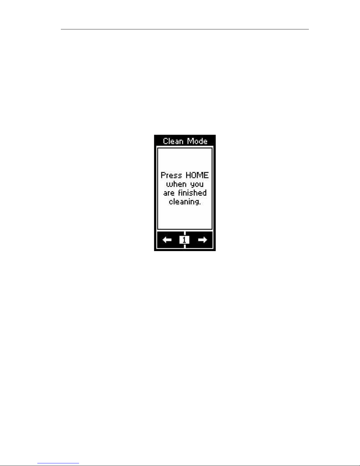
CLEANING
Occasional cleaning may be required, depending on use. It is
recommended that you create a “Clean” button somewhere on the
Home page of the RK2. This button should link to a page that does
not contain commands or macros that could be inadvertently
executed while cleaning the unit. The “Clean” page could contain
a text message or graphic of your choosing such as:
To clean your RK2, lightly dampen a lint-free cloth with a glass
cleaner or mild detergent, and wipe the touchscreen, surrounding
display bezel, and buttons.
Page 13

RK2 Universal System Controller
6
GETTING STARTED
The RK2 is turned-on by simply applying power to it. RTI
provides two power supply solutions which are sold separately:
Single Unit Power Supply
§ 16VDC, 1.6Amp
§ Provides power for up to eight RK2’s
§ Part Number: 40-210285-22
CB-4 Connecting Block
§ Includes 16VDC, 4.3Amp power supply
§ Provides power for up to twenty RK2’s
§ Provides a convenient connection hub
§ Part Number: 10-210052-11
After powering down, the RK2 is activated by touching any area
of the touchpanel display. The RK2 turns-on instantly from its
sleep mode.
Page 14

Introduction
7
REMOTE REFERENCE
Integrated
Mounting Wings
Touchpanel
LCD Display
Ambient Light
Sensor
Plasma Friendly
Infrared Receiver
USB
Programming Port
Control Port
Removable
Terminal Block
Rear View
Front View
Power LED
Power Button
Home Page
Button
Function
Buttons
Page 15

RK2 Universal System Controller
8
Page 16

9
Chapter 3. Operation
THE TOUCHSCREEN DISPLAY
The RK2 touchscreen display is organized into a series of pages.
Normally each page contains objects (buttons, text, graphics, etc.)
that are related in some way. For instance, they may all display
information necessary for controlling a particular CD player.
By default, the RK2 has one Home page—all other pages are
normally accessed from links on the Home page. In addition, any
page can contain buttons with a link to any other page.
Normally the Home page is used to display the names of the A/V
sources and other devices being controlled. The RK2 will support
200 pages including the Home page.
A representation of a programmed Home page is shown below:
In order to contain more than one screen of buttons and graphics,
a page can consist of up to twelve frames. To change frames, press
the frame Left or frame Right buttons on the lower
touchscreen.
Page 17

RK2 Universal System Controller
10
THE CONTROL PANEL PAGE
The Control Panel page can be displayed by pressing and holding
the frame number box at the bottom of the touchscreen
continuously for 3 seconds.
You can also access the Control Panel page by assigning a
“Control Panel” page link to a button using the TheaterTouch
Designer software.
The Control Panel consists of the following three frames:
To change frames, press the frame Left or frame Right
buttons on the lower touchscreen.
To return to the user program, press the Home button.
Page 18

Operation
11
ADJUST CONTRAST
This button displays a window that allows you to adjust the LCD
contrast. Press the Left Arrow or Right Arrow keypad buttons to
adjust. Press the OK button in the window to close.
IR RECEIVER
This button displays a window that allows you to enable or
disable the front panel IR Receiver. The IR Signal graphic inverts
color to indicate IR data and/or noise being detected by the
receiver. This helps to determine if you should enable the receiver
in a particular environment.
On means the IR Receiver is enabled. This will cause infrared data
to be passed through to the signal output pin.
Off means the IR Receiver is disabled.
Press the OK button in the window to close.
Page 19

RK2 Universal System Controller
12
BEEPER
This button displays a window that allows you to turn the audible
beep on or off. The beeper provides feedback that a button was
pressed.
On means the beeper is enabled.
Off means the beeper is disabled.
Press the OK button in the window to close.
LIGHT SENSE
This button displays a window that allows you to enable or
disable the front panel ambient light sensor.
On means the Light Sensor is enabled. This will cause the
backlight brightness to dim or brighten in response to changes in
the ambient room light.
Off means the Light Sensor is disabled.
Press the OK button in the window to close.
Page 20

Operation
13
ACTIVE BACKLIGHT
This button displays a window that allows you to adjust the
backlight brightness for the RK2 Active mode.
If the light sensor is disabled, there is only one backlight level to
adjust. Press the left arrow or right arrow buttons in the window
to adjust. Press the OK button in the window when finished.
With the light sensor disabled, the backlight brightness will
always stay at the same level. The backlight level can, however, be
set differently for the unit’s Idle mode.
If the light sensor is enabled, there are two backlight levels to
adjust. Press the left arrow or right arrow buttons in the window
to adjust. Press the OK button in the window when finished.
With the light sensor enabled, the backlight brightness will
automatically change between the two levels, depending upon the
ambient lighting conditions. Also, the backlight level can be set
differently for the unit’s Idle mode.
Page 21

RK2 Universal System Controller
14
IDLE BACKLIGHT
This button displays a window that allows you to adjust the
backlight brightness for the RK2 Idle mode.
If the light sensor is disabled, there is only one backlight level to
adjust. Press the left arrow or right arrow buttons in the window
to adjust. Press the OK button in the window when finished.
With the light sensor disabled, the backlight brightness will
always stay at the same level. The backlight level can, however, be
set differently for the unit’s Active mode.
If the light sensor is enabled, there are two backlight levels to
adjust. Press the left arrow or right arrow buttons in the window
to adjust. Press the OK button in the window when finished.
With the light sensor enabled, the backlight brightness will
automatically change between the two levels, depending upon the
ambient lighting conditions. Also, the backlight level can be set
differently for the unit’s Active mode.
Page 22

Operation
15
TIME OUT
This button displays a window that allows you to adjust the
amount of time the unit stays in active mode after the last button
press. The time is variable from 1 second to 60 seconds (the
default is 10 seconds). Press the arrows to the left or right of the
Time Out setting to adjust the time. Press the OK button in the
window to close it.
CHANGE PASSCODE
This button displays a window that allows you to set the passcode
that is used to limit access to the Clear All function on the Control
Panel page, as well as the Button Lockout function that is
available on all buttons.
When you press the CHANGE PASSCODE button, the screen will
prompt you to enter the old passcode. Press the ENTER button
after entering the numbers.
(The default code is 0000).
Page 23

RK2 Universal System Controller
16
Now enter a new four-digit passcode.
You will be prompted to enter the new four-digit passcode again
for confirmation.
When new code is entered successfully, the “Code Changed”
window will pop up to let you know you have changed the
passcode.
Do not forget the passcode!
Page 24

Operation
17
CLEAR ALL
This button displays a window that will allow you to erase the
current user program in the RK2. When the button is pressed, you
will be prompted to enter the current passcode. If the proper code
is entered, the entire user program in the RK2 will be erased.
Warning! This will erase the entire user program in the RK2.
Once this is done there is no way to restore it, except by reloading
the program from the TheaterTouch Designer software!
If you inadvertently press the CLEAR ALL button, simply press the
ENTER keypad button without entering the passcode and you will
be returned to the Control Panel page.
Page 25

RK2 Universal System Controller
18
Page 26

19
Chapter 4. Installation & Programming
The RK2 is designed for flush-mount installations in walls or
cabinets. It requires an available mounting depth of 2.0 inches
(50mm) from the front surface of the wall. There are numerous
options for mounting and wiring the RK2.
Note: Make sure to use the included cardboard cut-out
template to create the correct size opening in the wall.
MOUNTING HEIGHT
The recommended mounting height for the RK2 is between 54”
(1.37m) and 60” (1.52m) from the bottom of the faceplate.
The recommended
mounting height is
54" - 60" (1.37m - 1.52m)
50º
50º
57"
(1.45m)
12"
(.305m)
3'-10"
(1.17m)
6'-2"
(1.88m)
RK2 side view: Viewing angle at 57"
Page 27

RK2 Universal System Controller
20
MOUNTING OPTIONS
The RK2 has integrated mounting wings for retrofit installation in
new or existing construction. Additionally, the RK2 can be
directly attached to certain walls (wood, etc.) using screws.
An optional drywall rough-in bracket (RTI part #: 40-210306-16) is
available for conveniently locating the RK2 in new construction
installations.
WIRING CONNECTION OPTIONS
The RK2 can be wired either from the Control Port or the
Removable Terminal Block. A minimum of 3-conductor wire is
required for basic operation (+16VDC, GND, and IR DATA).
CAT5 cable can be used to power the RK2 up to 1000 feet (300m) if
a full wire pair is used for both +16VDC and GND. For longer
distances use the following size of unshielded multi-conductor
cable:
Wire Size Distance
20 AWG 1300’ (400m)
18 AWG 2000’ (600m)
Page 28

Installation & Programming
21
INFRARED
GROUND
POWER
Control Port Pin-Out
Pin 1
Pin 2
Pin 3
Pin 4
Pin 5
Pin 6
Pin 7
Pin 8
INFRARED
INFRARED
+16VDC
+16VDC
IR Emitter Connecting Block
(Industry Standard)
EMITTERS
INPUT
To IR receivers on A/V
equipment, lighting controls, etc.
RK2 Basic Wiring Connections
RK2 Power Supply
16VDC
PWR
Stand-Alone OperationControl-System Operation
Cat-5 Cable
20 AWG (min.) wire
- or - full Cat-5
pairs
(Future Use)
(Future Use)
Optional CB-4 Connecting Block(s)
RP-6 Remote Control Processor
Cat-5 Cable
CB-4 Power
Supply
16VDC
RP-6
Power
Supply
GROUND
GROUND
RS-485 +
RS-485 -
Page 29

RK2 Universal System Controller
22
RK2 REMOVABLE TERMINAL BLOCK DESCRIPTION
TERMINAL NAME DESCRIPTION
+16VDC
Positive power supply
connection. This should be
connected to 9VDC-16VDC.
GND
Common ground connection. Use
this ground reference for any
device that is connected to any of
the other pins on the connector.
IR
DATA
High current (200mA) IR output
connection. This can be used to
power up to 10 infrared mini-
emitters, an IR blaster, or
extending IR control over a long
distance (1000 ft. max).
PWR
STATUS
Voltage power sensing input
connection. This can be
connected to a trigger output or
switched outlet (using a small
wall-mount power supply) on
A/V equipment, current sensors,
light sensors, etc. The ON state
sense voltage is 3VDC – 20VDC.
The OFF state sense voltage is
0VDC - 2VDC.
GND
Common ground connection. Use
this ground reference for any
device that is connected to any of
the other pins on the connector.
Page 30

Installation & Programming
23
RELAY
CTRL
Voltage trigger output. This can
be used to control speaker relays,
screens, window coverings, etc.
The output can supply up to
100mA and has a voltage equal to
the input supply.
AUX
STATUS
Voltage power sensing input
connection. This can be
connected to a trigger output or
switched outlet (using a small
wall-mount power supply) on
A/V equipment, current sensors,
light sensors, etc. The ON state
sense voltage is 3VDC – 20VDC.
The OFF state sense voltage is
0VDC - 2VDC.
TRIG
OUT
Voltage trigger output. This can
be used to control speaker relays,
screens, window coverings, etc.
The output can supply up to
100mA and has a voltage equal to
the input supply.
PROGRAMMING THE RK2
The RK2 is programmed using RTI’s TheaterTouch Designer™
software. RTI dealers can download the software free of charge
from:
www.rticorp.com/dealers
A PC running Windows® 98SE or higher with a USB port is
required. The required USB cable is included with the RTI IR-PRO
dealer kit.
Page 31

RK2 Universal System Controller
24
Page 32

25
Chapter 5. Troubleshooting
If you are having problems with your RK2, please read these
troubleshooting tips before contacting technical support.
If you continue to have problems, see Chapter 6 for more
information on contacting RTI technical support.
DISPLAY IS DIM, BLANK OR UNREADABLE
Make sure the external power supply is properly secured to the
RK2, and it is functioning properly.
Try adjusting the contrast level from the Control Panel page
(Refer to Chapter 3 for more details).
By nature, the contrast of an LCD screen changes with
temperature, so if the display is cold it will appear dark and will
return to normal as it warms.
USB COMMUNICATION PROBLEMS
Verify that your PC is running Windows® 98SE or higher.
Verify that the RK2 is present in the Human Interface Devices
section of the Device Manager within the Windows® Control
Panel.
Make sure you are using the programming cable that was
supplied by RTI and that both ends are connected securely.
Make sure the PC detects the presence of the RK2. If it doesn’t,
unplug the USB cable, wait for about ten seconds, and plug it in
again.
If the download fails after some data has been transferred, try resending the program.
Page 33

RK2 Universal System Controller
26
IR CODE PROBLEMS
If you are using an IR repeater system, make sure it is working
correctly with the original OEM remote. If not, you will need to
troubleshoot the IR repeater system.
If you are still having problems, try adjusting the IR code
“Minimum Repeats” value in the TheaterTouch Designer
programming software.
If the IR code is executed inside a macro that contains multiple IR
codes, try inserting a small time delay before the problem code. If
there already is a delay, try increasing it.
Page 34

27
Chapter 6. Service and Support
UPDATES AND NEW PRODUCTS
For news about the latest updates, new product information and
accessories, please visit our web site at:
www.rticorp.com
CONTACTING REMOTE TECHNOLOGIES INCORPORATED
For general info, you can contact RTI at:
Remote Technologies Incorporated
Tel. (952) 253-3100
Fax (952) 253-3131
info@rticorp.com
www.rticorp.com
RTI TECHNICAL SUPPORT
At RTI, customer service and satisfaction is an utmost priority. If
you are encountering any problems or have a question about your
RTI product, please contact RTI Technical Support for assistance.
RTI provides technical support by telephone, fax or e-mail. For the
highest quality service, please have the following information
ready, or provide it in your fax or e-mail.
§ Your Name
§ Company Name
§ Telephone Number
§ E-mail Address
§ Product model and serial number (if applicable)
Page 35

RK2 Universal System Controller
28
If you are having a problem with hardware, please note the
equipment in your system, a description of the problem, and any
troubleshooting you have already tried.
If you are having a problem with software, please note what
version you have installed, the operating system on your PC, a
description of the problem, and any troubleshooting you have
already tried.
If you are calling about a software or programming question or
problem, please be at you computer when you place your call.
This will considerably speed up the troubleshooting process.
For Technical Support or assistance with your RTI product,
contact RTI at:
(952) 253-3137
support@rticorp.com
www.rticorp.com/support
For questions regarding Service or Repair of your RTI product,
contact RTI at:
(952) 253-3136
service@rticorp.com
www.rticorp.com/service
Please do not return products to RTI without return authorization.
Page 36

29
Specifications
Power 9 - 16 VDC, .3 Amp max
Power Management Adjustable backlight
brightness/power down
time
Display High-contrast STN LCD
128 x 64 pixels (Dark Blue
on White)
Touchscreen Digital Matrix, 7 x 2
Touchscreen never needs
calibrating
Display Size (L x W) 2.4 in. x 1.3 in. (61mm x
33mm)
Display Backlight Display: white LED
Keypad: blue/amber LED
Infrared Output Port 200mA output
Drives up to 1000 feet
(300 meters) of wire
Operating Temperature +32 °F to +122 °F
(0 °C to +50 °C)
Operating Humidity 5% to 95% non-
condensing
Total System Memory 256K Bytes Flash
(non-volatile)
Device Capability Total number of devices
is limited only by
memory
Page 37

RK2 Universal System Controller
30
Macro Capability Unlimited steps allowed
in a single macro
Total number of macros
is limited only by
memory
Macro capability on
every button
Communications USB programming port
Enclosure High-impact molded
ABS plastic, black/gray
Front Plate High-impact molded
ABS plastic, white
Mounting Integrated mounting
wings, or screws through
front bezel
On Wall Plate Dimensions (H x W x D) 5.1 in (129 mm) x 4.65 in
(118 mm) x .17 in (4.3 mm)
Installation Cut-Out (H x W) 4.5 in. (117mm) x 4.0 in.
(102mm)
Total Depth in Wall 1.4 in. (33mm)
Weight 10 oz (284g)
Warranty One Year (Parts &Labor)
All specifications are subject to change without notice.
Page 38

IR-PRO
Professional Infrared Code Capture System
Remote Technologies Incorporated
Remote Technologies IncorporatedRemote Technologies Incorporated
Remote Technologies Incorporated
7651 Anagram Drive
Eden Prairie, MN 55344
Tel: 952-253-3100
Fax: 952-253-3131
www.rticorp.com
©
2007 Remote Technologies Inc. All rights reserved. Printed in Taiwan.
It’s Under Control
®
IR-PRO
Professional Infrared Code Capture System
RK2
In-Wall Universal Controller
 Loading...