

Page 1
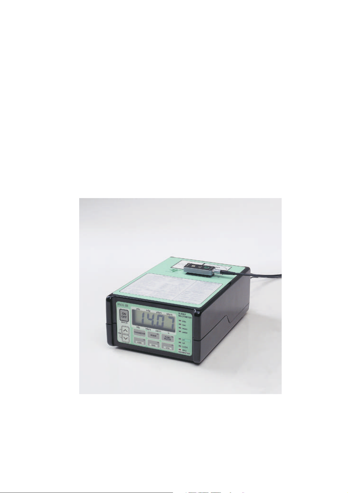
PMX-III
X-ray multimeter version 6.0
oRTIgo version 3.0
Page 2

Page 3

Declaration of conformity
We, RTI Electronics AB, Göteborgsvägen 97 / 50, SE-431 37 MÖLNDAL, Sweden,
declare under our sole responsibility that the product:
Product name:
Type of equipment:
PMX-III
X-ray multimeter; kVp, exposure time, and dose meter
Intended use of this product:
Accessory to diagnostic X-ray equipment, to be used
Model name:
R/M, R/CT, PH
for service and quality control.
is in conformity with the following standards:
Medical electrical equipment
Part 1: General requirements for safety (COUNCIL DIRECTIVE 93/42/EEC, Annexes
V and VII)
Part 2: Collateral standard: Electromagnetic compatibility - Requirements and tests
(EN 60601-1-2: 1993)
following the provisions of the 93/42/EEC Medical Devices Directive.
Mölndal, 1998-11-13, ……………………………………
Lars Herrnsdorf, Vice President
Address: RTI Electronics AB Göteborgsvägen 97 / 50 SE-431 37 MÖLNDAL Sweden
Phone: +46 (0)31 746 36 00 Fax: +46 (0)31 27 05 73 E-mail: info@rti-e.se Web: www.rti-e.se
2-CE-03000-2 Tillverkardeklaration PMX-III.DOC
Page 4

Page 5

NOTICE
NOTICE
RTI Electronics AB reserves all rights to make changes in
the PMX-III family of meters and the information in this document
without notice.
RTI Electronics AB assumes no responsibility for any errors or consequential
damages that may result from the use or misinterpretation of any information
contained in this document.
© Copyright 1999, RTI Electronics AB. All rights reserved.
Contents of this document may not be reproduced in any form without
permission of RTI Electronics AB.
NOTE!
This user manual is valid for PMX-III with the following version: 6.0
IBM is a registered trademark of International Business Machines Corporation.
HP is a registered trademark of Hewlett-Packard Company.
Appletalk and Macintosh are registered trademarks of Apple Computer, Incorporated.
Microsoft, Windows and Windows 95 are registered trademarks of Microsoft Corporation.
Pentium is a registered trademark of Intel Corporation
RTI Electronics AB
Göteborgsvägen 97 / 50
SE-431 37 MÖLNDAL
Sweden
Phone: Int +46 31 746 36 00
Fax: Int +46 31 270 573
E-mail: info@rti-e.se
Web: http://www.rti-e.se
PMX-III Manual 1999-03/6.0B I-1
Page 6

PREFACE
Chapter 1 Gives an introduction to the PMX-III.
Description of ADI, applications and typical use
Chapter 2 Describes general functions and connectors
Chapter 3 Set up the system for measurements
Chapter 4 Learn to make basic QC measurements.
Chapter 5 Service and Maintenance related measurements
II,, Dose/frame, DSI, and light measurements.
PREFACE
Chapter 6 Remote control of the PMX-III using oRTIgo.
Chapter 7 Display code list and kVp correction graph.
Chapter 8 Precautions and maintenance.
Chapter 9 Detector range and detector selection guide,
problem report document.
Chapter 10 Hints and troubleshooting, backup of calibration data
Index Important words are listed in alphabetical order.
It is advisable to read through the user manual at least once to gain
familiarity with the terms used and the capabilities of the PMX-III.
It is possible to make measurements quickly with a minimum of reading.
To do this read the instructions on the top panel of the instrument.
Consult the PMX-III reference manual for more specific information.
Note! The PMX-III is intended for service and quality control of diagnostic X-ray
equipment. It is not intended for for use during or together with
diagnostic examinations of patients.
I-2 1999-03/6.0B PMX-III Manual
Page 7

TABLE OF CONTENTS
I-NOTICE ............................1
I-PREFACE ...........................2
1-INTRODUCTION .......................7
1.1 Overview .........................7
1.2 Package Information and Changes Version 6.0 ....8
1.3 Options and Accessories ................8
1.4 Application Notes ....................8
1.5 About oRTIgo Version 3.0................8
1.6 About ADIs ........................9
1.6.1 What is the Function of an ADI ............9
1.6.2 What to do when Changing an ADI..........9
1.6.3 Any Precautions? ...................9
TOC
1.6.4 How to Choose the Correct ADI Module .......9
1.7 Shortform Detector Selection Guide ..........10
1.8 Typical Use .......................11
2-DESCRIPTION OF PMX-III ..................13
2.1 Front Panel ........................13
2.2 The Display........................13
2.3 The LED Indicators ...................14
2.4 Front Panel Keys ....................16
2.5 Back Panel and AMP-1 .................17
2.6 The Battery Case ....................18
2.7 Top Panel.........................19
2.8 Special Remarks for Use of ADI 8/A(P1) ........20
2.9 AMP-1 Front Panel....................21
2.10 Operation of Principle of the Electrometer .....21
3-HOW TO SET UP THE SYSTEM ..............23
4-BASIC QC MEASUREMENTS ................25
4.1 kVp and Time (Multimeter Mode) ...........25
PMX-III Manual 1999-03/6.0B 3
Page 8

4.1.1 PARAMETER.....................25
4.1.2 MODE ........................25
4.1.3 When to use SET and LOCK modes .........25
TOC
4.1.4 When and how to use manual LOCK mode .....26
4.1.5 When to use LF and HF: ...............26
4.1.6 TUBE/FILTER ....................27
4.1.7 Measurement with the MAM/RAD version ......28
4.1.8 Default values for F3-F5 (MAM/RAD version) ....29
4.1.9 CT kVp Measurement with the CT/RAD version ...29
4.2 Dose and Dose Rate (Dosimeter Mode)........31
4.2.1 When and How to Use Manual LOCK Mode .....32
4.2.2 How to Use Free Run/Trig Mode ...........32
4.2.3 Active Keys ......................33
4.2.4 How to Make a Measurement ............35
4.3 The Waveform Analyzer ................36
4.3.1 Examples of waveforms ...............37
4.3.2 Waveform flowchart .................38
4.4 Using preamplifier AMP-1 ................39
4.5 Measurements with the AMP-1 ............41
4.5.1 General .......................41
4.5.2 Detector Range and Identification Codes ......42
5-SERVICE / MAINTENANCE .................43
5.1 Introduction .......................43
5.1.1 New Version of Firmware for PMX-III. ........43
5.1.2 Extension Cable Added. ...............44
5.1.3 Probe Holder Added. .................44
5.1.4 ADIs Removed from Detector Cables. ........44
5.1.5 Maintenance. .....................44
5.2 Entrance Dose Rate Measurements ..........45
5.2.1 Very Low Entrance Dose Rate to an Image Intensifier 45
5.2.2 Hints .........................47
5.2.3 Example of Dose Rate Waveforms .........48
5.3 Fluoroscopy low mA ..................48
5.3.1 II-Entrance Dose Rate (µGy/s) ............48
4 1999-03/6.0B PMX-III Manual
Page 9

5.4 Exposure Dose .....................49
5.4.1 Fluorography and Radiography............49
5.5 Measurement of kVp...................50
5.5.1 Long Exposure time, Skin Dose, and Dose Rate
(SET MODE) ........................50
5.5.2 Short Exposure Time, Skin Dose and Dose Rate
(MANUAL LOCK MODE) ..................51
5.6 Light Measurements, Detector and Adapters .....52
5.6.1 Introduction ......................52
5.6.2 Measurement of Luminance (cd/m²) .........55
5.6.3 Measurements on CRTs and Film Viewing Boxes . . 56
5.6.4 Ambient Light and Other Sources of Error ......57
5.7.3 Measurement of Illuminance (lx) ...........59
5.7 Examples of Field Measurements ...........60
5.7.1 Check the total Contrast Range for the System,
From the Image Intensifier to the Monitor. .........60
5.7.2 Check that the Dose and Dose Rate Level is within
Specification for all II Formats. ...............61
6-REMOTE CONTROL USING ORTIGO ............63
6.1 Introduction .......................63
TOC
6.2 oRTIgo version 3.0....................64
6.3 Connecting PMX-III to a Computer ...........65
6.4 Start oRTIgo 3.0 .....................66
6.5 What is a Record.....................67
6.6 Application example...................68
6.7 List of Hotkeys and Short Cuts .............76
6.7.1 General ........................76
6.7.2 Waveform Analyzer..................78
6.7.3 Text Editor and NotePad ...............79
7-DISPLAY CODES, SENSITIVITY AND FILTRATION ....81
7.1 Display codes ......................81
7.1.1 Most Common Display Codes ............81
7.1.2 Description of the Display Codes ...........82
7.2 KVp Sensitivity Graph ..................85
PMX-III Manual 1999-03/6.0B 5
Page 10

7.3 Filtration Dependence ..................86
7.4 KVp Correction Graphs .................88
7.4.1 Radiographic - CA-1, 2.0-5.5 mm Al .........88
TOC
7.4.2 Radiographic CA-1, 3.0, 4.0, and
5.0 mm Al+0.1 mm Cu ...................89
8-PRECAUTIONS AND MAINTENANCE............91
8.1 Safety Rules .......................91
8.2 Precautions .......................91
8.3 Maintenance .......................92
9-Notes and Reports .....................93
9.1 Application Notes Related to PMX-III..........93
9.2 Problem report ......................98
10-HINTS AND TROUBLESHOOTING .............99
10.1 Hints...........................99
10.1.1 General Info .....................99
10.1.2 oRTIgo Measurement ................99
10.2.1 Dose Measurements ................101
10.2.2 Questions on kV Measurements ..........104
10.2.3 Light Measurements.................104
10.2.4 General Questions .................105
10.2 Troubleshooting ....................106
10.3 Save EEPROM and ADI data..............108
10.3.1 Backup of internal EEPROM and ADI Modules . . 108
10.4 Restoring data from backup ..............110
10.4.1 Restore the content of PMX-III internal EEPROM . 110
INDEX ..............................113
6 1999-03/6.0B PMX-III Manual
Page 11
INTRODUCTION Overview
1 INTRODUCTION
1.1 Overview
PMX-III is a combined dosimeter and multimeter with a waveform analyzer
for both stand alone and remote control use.
PMX-III operates in four different main modes:
As a dosimeter, measuring dose and dose rates simultaneously.
•
The PMX-III can be operated from the control room. Functions as hold, normalize,
auto range, and auto reset are available. Use of light detectors or current detectors
makes it possible to measure , cd/m
As a multimeter measuring kVp, time, dose, and dose rate simultaneously.
•
As a waveform analyzer
•
• Remote controlled by the oRTIgo software.
2
, lx , mA, and mAs.
PMX-III can be used to measure the following:
• Dose, dose rate, and
dose/frame
• Light output from monitors
and film viewing boxes
using L100 light detector
• mA and mAs using
optional current probes
1
Chapter
•
Mammo kVp and
diagnostic kVp accuracy
•
Exposure time accuracy
•
Reproducibility of kVp,
time, and output
•
mAs-linearity
•
HVL
•
kV and radiation output waveform
•
Dose rate, mA and light waveforms
•
Dose/frame, frame/s and monitor frequency (Hz) automatically using waveform
analyzer
PMX-III version 6.0 can be programmed to always start up in dosimeter mode
or multimeter mode or what mode was used when last powered off.
PMX-III Manual 1999-03/6.0B 7
Page 12
About oRTIgo Version 3.0 INTRODUCTION
1.2 Package Information and Changes Version 6.0
Please read the addendum to the reference manual.
1.3 Options and Accessories
Please study the RTI’s product catalogue that should be included in the
Chapter
package. The latest information can be found on RTI’s web site www.rti-e.se.
1
1.4 Application Notes
For A list of available application notes, see chapter 9 “Notes and Reports”.
All application notes can be downloaded from our web page . They are stored
as pdf files.
1.5 About oRTIgo Version 3.0
This manual briefly describe oRTIgo version 3.0 in chapter 6, for detail
information please study the oRTIgo user manual.
Example of dose rate waveform with automatic calculation of dose/frame and frame/s
8 1999-03/6.0B PMX-III Manual
Page 13
INTRODUCTION About ADIs
1.6 About ADIs
1.6.1 What is the Function of an ADI
The ADI contains the calibration factors for the detector with the same serial
number. It also informs the PMX which detector is being used and transfers
data to PMX-III for optimize the use of the detector.
As an example the selected ADI can inform if PMX-III should display dose
rate or dose values after power on.
1
Chapter
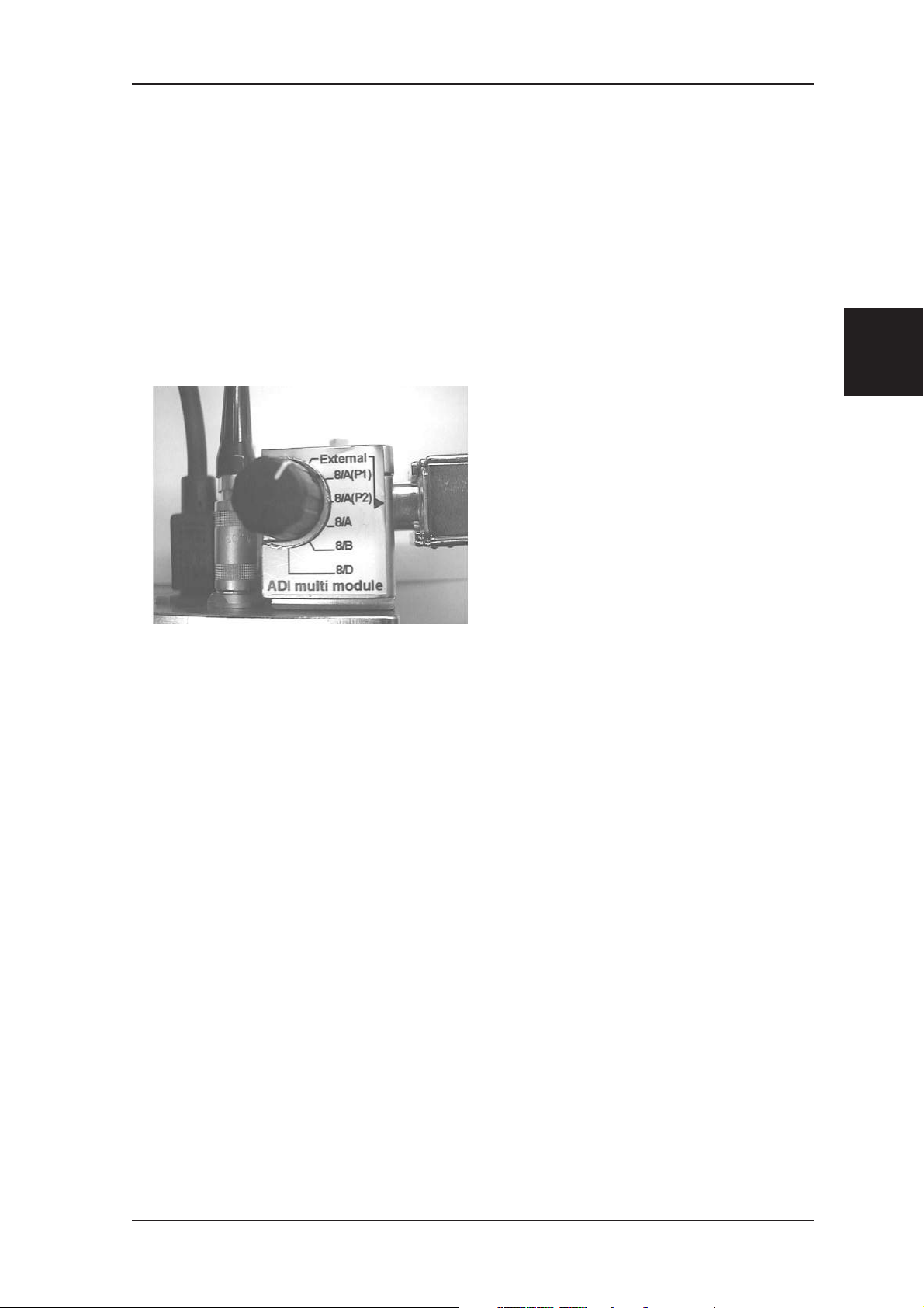
ADI multi module (replaces the need for
up to 5 separate R100 ADIs, option)
1.6.2 What to do when Changing an ADI
The PMX reads the ADI at power on, after each exposure in multimeter mode
and when pressing Reset. The display will indicate the type of ADI. Pressing
reset longer than2sindosimeter mode will make a new offset calibration. A
“c” is displayed after reset to indicate calibration.
Do not expose during the time “c” is displayed.
1.6.3 Any Precautions?
The ADI contains an EEPROM with the probe calibration data. The
calibration data can be downloaded to your PC by the oRTIgo program
delivered with the PMX. In case of deletion (Er.30 message) this data can
then be restored again. Also the internal Eeprom can be restored the same
way. See chapter 10 “Hints and Troubleshooting” for more information.
1.6.4 How to Choose the Correct ADI Module
See the Short form Detector Selection Guide below.
PMX-III Manual 1999-03/6.0B 9
Page 14
Shortform Detector Selection Guide INTRODUCTION
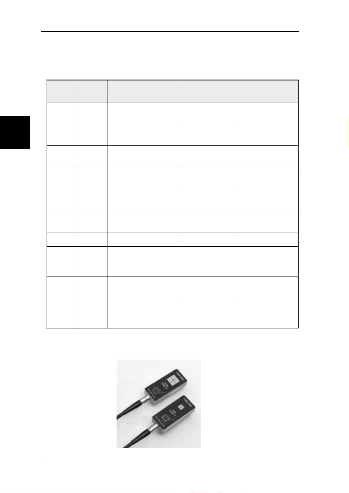
1.7 Shortform Detector Selection Guide
Chapter
1
Type
ADI
Code
R100 8/A
R100 8/A(P1)
R100 8/A(P2)
R25 7/B
R100 8/D
L100 6/U
Beam Quality Typical Use
50-150 kV
W/23 mm Al
50-150 kV
W/23 mm Al
50-150 kV
W/23 mm Al
50-150 kV
W/3mmAl
25-35 kV
Mo/ 30m Mo
Luminance
CIE filter
film dose / rate 0,001-40 mGy/s
II dose rate input 0,03-0,46 µGy/s
II dose rate input 0,10-46 µGy/s
Skin dose / rate 0,004-160 mGy/s
skin dose to breast 0,002-90 mGy/s
Monitor adapter
Film viewing box
Typical Range
(rate)
0,1 cd>1000 cd/ m
0,5 cd>9999 cd/ m
L100 6/Y Illuminance, diffusor LUX adapter 0,25 - 4000 lx
Invasive mA & mAs
MAS-1 5
(use the mA
mA and mAs 0,10-2000 mA
test socket)
2
2
MAS-2 4
MAS-3 J
The R25 and R100 are
ideal for field service
situations. They do not
need corrections for
temperature or pressure
an need no bias voltage.
Non-invasive mA &
mAs
State of the art
non-invasive mA &
mAs
mA and mAs 50-2000 mA
mA and mAs 0,10-2000 mA
10 1999-03/6.0B PMX-III Manual
Page 15

INTRODUCTION Typical Use
1.8 Typical Use
(ADI=Automatic Detector Identification)
Application
Cont. fluoroscopy 3/6
mA
DSI/spotfilm fixed
current
DSI/spotfilm falling
load
Ambient light level 6/Y Illuminance, (lx)
Skin dose
Monitor light output
with test pattern
mA, mAs, and mA
waveform check
ADI
8/A(P1) Dose rate only
8/A(P2)
8/A
7/B
6/U Luminance (cd/m
5
Measurements
Dose rate & dose rate
Dose rate & dose (less
sensitive)
Unfiltered beam (3mm
Al.)
with MAS-1 current
probe
Power on
Display
rate
dose
rate
dose
2
)
rate
dose
PMX
Display
code
8.AP1
8.A.P2
8.-A-
6.-y-
7.-B-
6.-Y-
MAS.1
1
Chapter
Determine dose/frame
and number/frames per
second
Determine monitor
vertical frequency
8/A(P2)
6/U
oRTIgo waveform
analyzer (see record
news1.dta)
oRTIgo waveform
analyzer (see record
news1.dta)
- Not valid
- Not valid
PMX-III Manual 1999-03/6.0B 11
Page 16

Chapter
1
Typical Use INTRODUCTION
This page is intentionally blank.
12 1999-03/6.0B PMX-III Manual
Page 17

DESCRIPTION OF PMX-III The Display
2 DESCRIPTION OF PMX-III
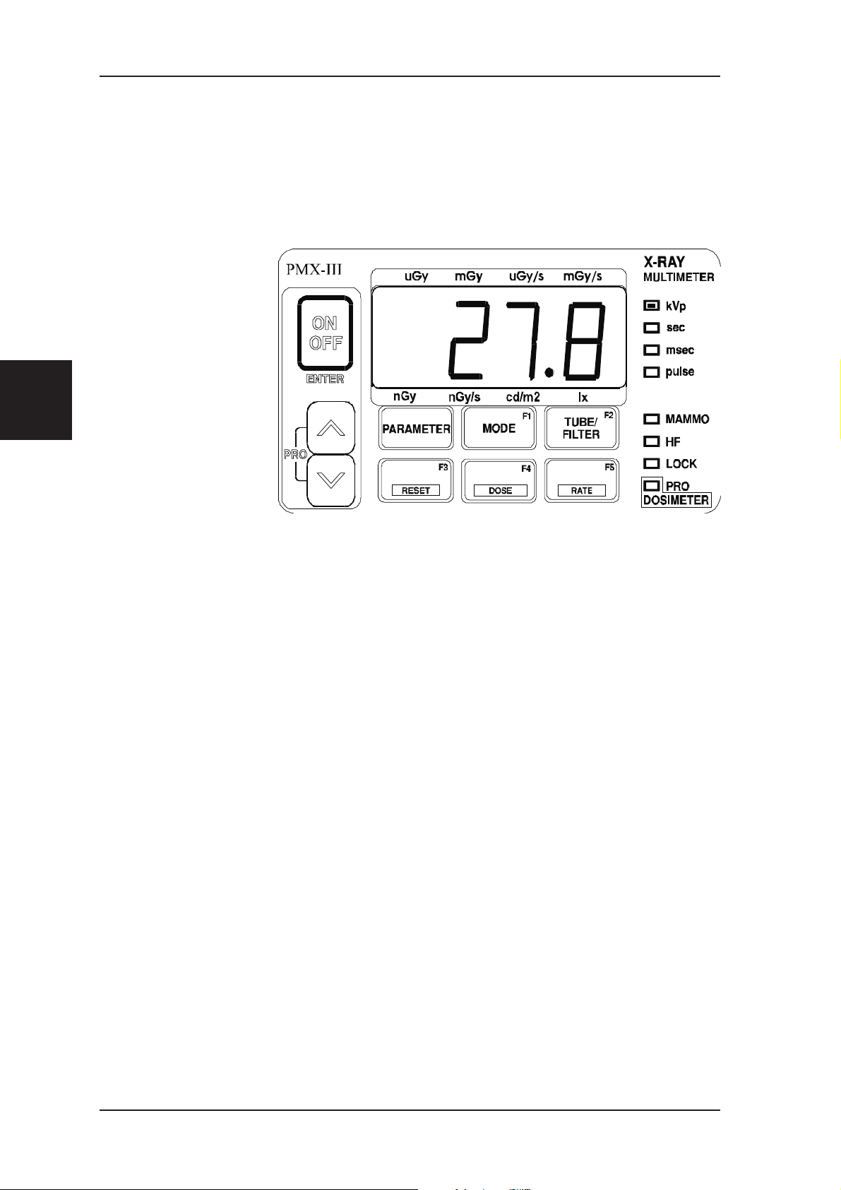
2.1 Front Panel
PMX-III is equipped with a membrane switch panel with 9 different switches,
one LCD display, and 8 LED indicators,4. Each time a key is pressed a beep
is generated to indicate that PMX-III has recognized the key.
2
Chapter
2.2 The Display
The display is a four digit LCD (liquid crystal display). The display is used to
show digits and text and to indicate dose and dose rate units. Dose and dose
rate are indicated at the top and bottom of the display.
The character “c” in the first position indicates that PMX-III is performing
internal calibrations. This is done after each exposure in multimeter mode and
when RESET is pressed in dosimeter mode.
When PMX-III operates in multimeter mode and is turned upside-down the
display information is automatically turned around. This function can be
turned off by means of the programming feature.
PMX-III Manual 1999-03/6.0B 13
Page 18
Chapter
2
The LED Indicators DESCRIPTION OF PMX-III
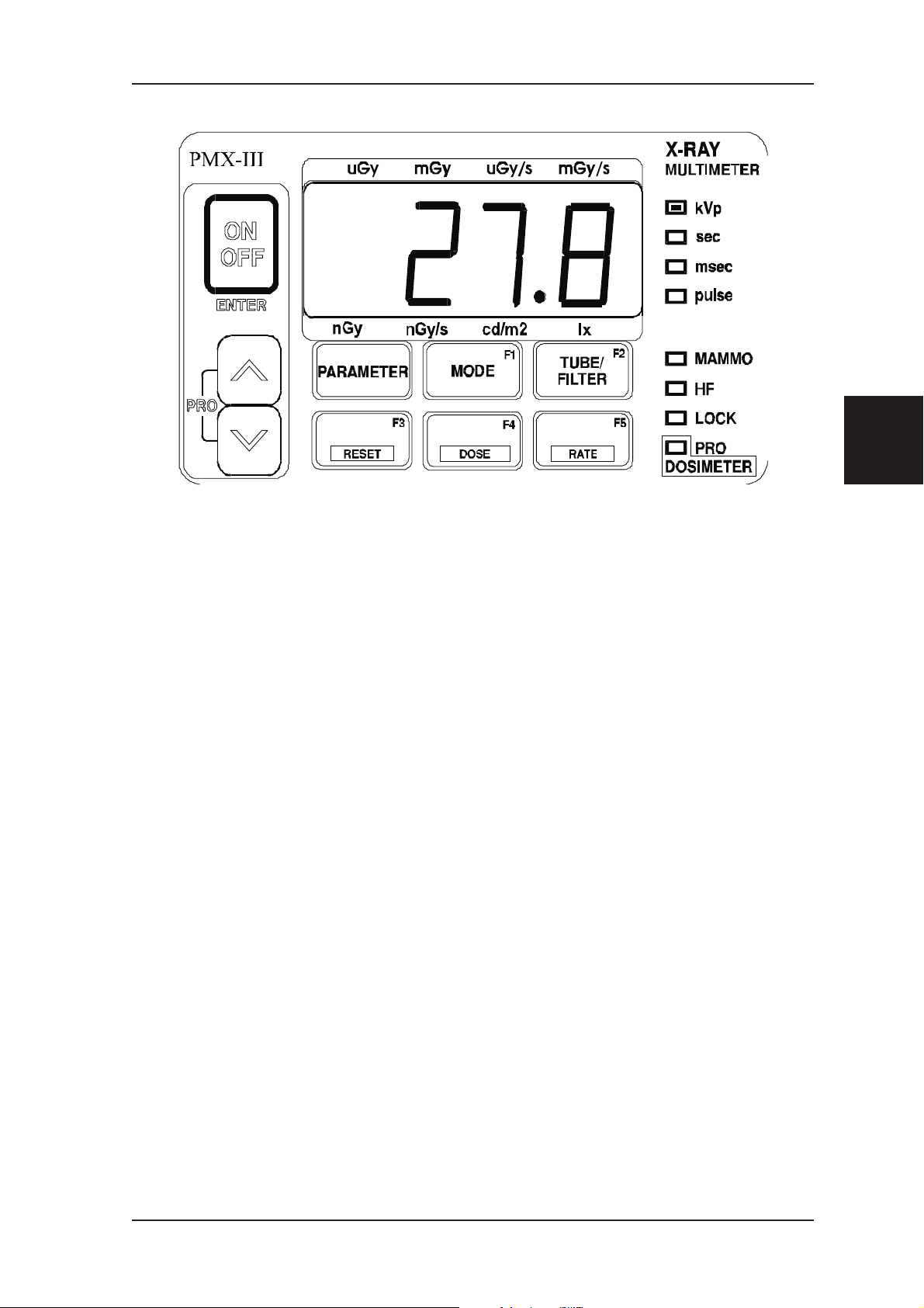
2.3 The LED Indicators
Eight LED indicators are used to indicate different parameters and modes of
operation. The LED indicators are turned on each time a measurement is
performed or a
function is selected.
In multimeter mode
the LEDs are on for
10 seconds and then
turned off to save
power. If the LEDs
are off, they can be
turned on again by
pressing the upper
cursor key.
In dosimeter mode
the LEDs are on
continuously.
The following LED indicators are on the front panel:
kVp Indicates tube voltage.
sec Indicates exposure time, measured in seconds.
msec Indicates exposure time, measured in
milliseconds.
pulse Indicates exposure time, measured in pulses.
14 1999-03/6.0B PMX-III Manual
Page 19
DESCRIPTION OF PMX-III The LED Indicators
2
Chapter
MAMMO ON: Indicates that the selected tube/fil
ter combination corresponds to a
mammo X-ray unit, i.e. the MAM
sensor area is used.
OFF: Indicates that the selected tube/fil-
ter combination corresponds to a
conventional X-ray unit, i.e. the
RAD sensor area is used.
HF ON: Indicates high frequency mode.
OFF: Indicates low frequency mode.
LOCK ON: Indicates LOCK or manual LOCK
mode.
OFF: Indicates SET mode.
-
PRO ON: Indicates PROGRAMMING mode
(the ON/OFF key acts as ENTER
key) or that the dosimeter is acti
vated.
DOSIMETER OFF Indicates multimeter measuring
mode.
PMX-III Manual 1999-03/6.0B 15
-
Page 20
Chapter
2
Front Panel Keys DESCRIPTION OF PMX-III
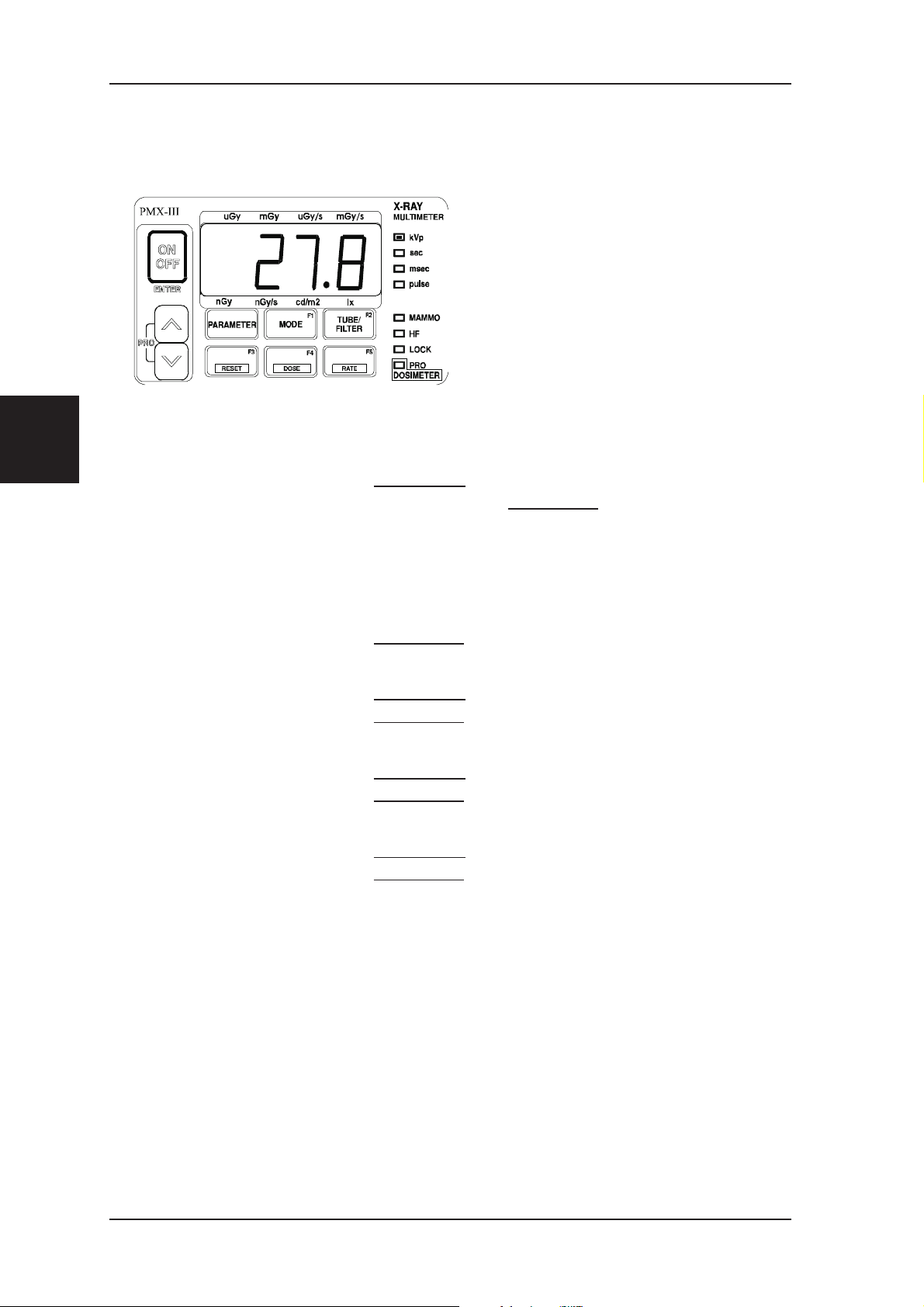
2.4 Front Panel Keys
The front panel keys are used to
choose different operating modes.
The same key may have different
functions in multimeter and
dosimeter modes.
The following keys are on the
front panel, see figure.
ON/OFF (ENTER) Power on/off and enter key in programming mode.
PARAMETER Multimeter:
ter an exposure.Dosimeter: No function.
MODE Changes operating mode
TUBE/FILTER Multimeter: Selects tube/filter combination.
Dosimeter:
F3/RESET Multimeter: Activates a setup table.
Dosimeter: Performs reset of the electrometer.
F4/DOSE Multimeter:
Dosimeter: Selects dose.
F5/RATE Multimeter: Activates a setup table.
Dosimeter: Selects rate.
Selects parameter to be displayed af
No function
Activates a setup table.
-
UPARR and
DNARR
16 1999-03/6.0B PMX-III Manual
Select different entries when moving around in the
menus.
Page 21
DESCRIPTION OF PMX-III Back Panel and AMP-1
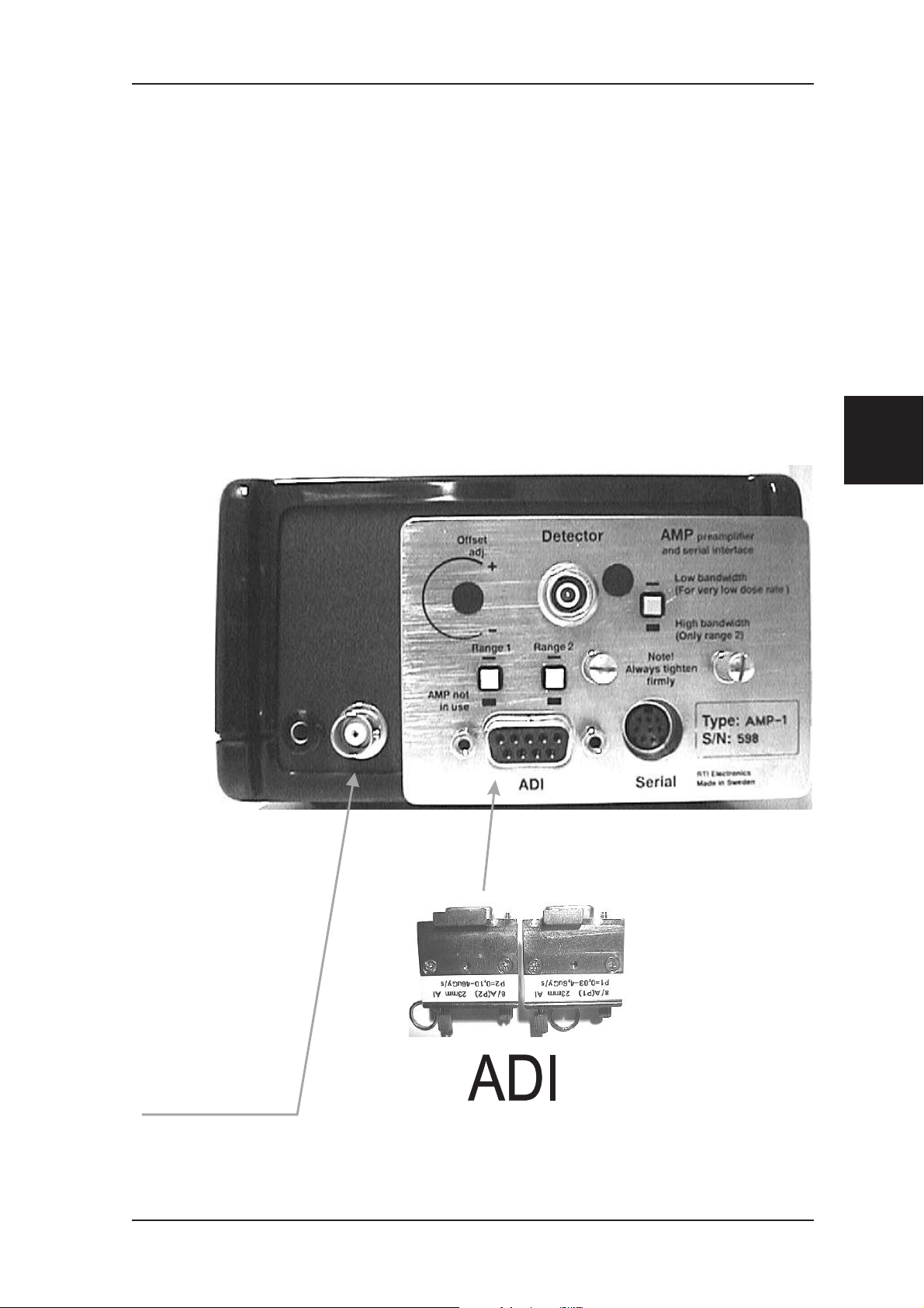
2.5 Back Panel and AMP-1
On the back panel the AMP-1 preamplifier/serial interface, there are four
connectors:
Detector connector input
•
9-pin ADI connector
•
8- pin MINI-DIN serial connector
•
BNC output
•
2
Chapter
A BNC connector
for connection to
an oscilloscope or
voltmeter.
PMX-III Manual 1999-03/6.0B 17
Page 22
Chapter
2
The Battery Case DESCRIPTION OF PMX-III
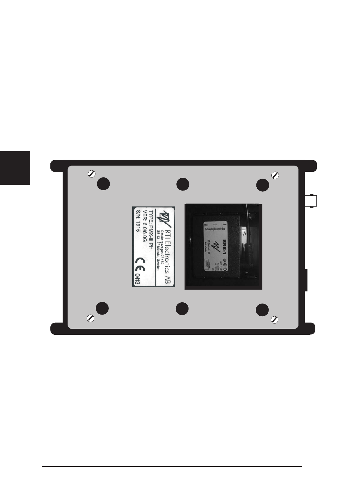
2.6 The Battery Case
Two high power alkaline “6LR61” 9 V batteries should be used if battery is
used. Preferable a Battery Replacement Box “BRB” for mains power could be
used instead of the two batteries.
18 1999-03/6.0B PMX-III Manual
Page 23
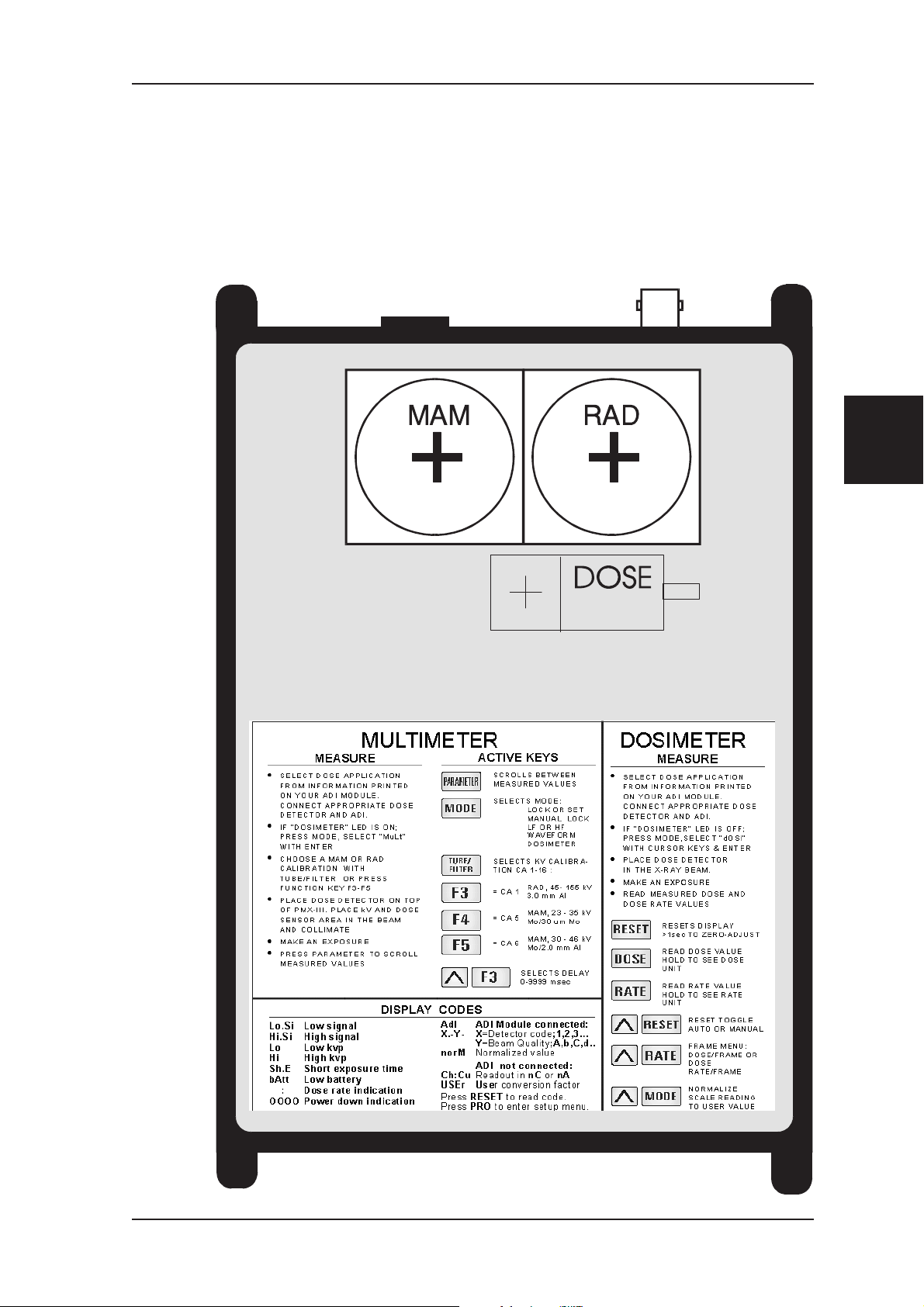
DESCRIPTION OF PMX-III Top Panel
2.7 Top Panel
On the top you will find indications for two sensor areas for MAM and RAD
and indication where to place the dose detector (in multimeter mode), and
user instructions for PMX-III
2
Chapter
PMX-III Manual 1999-03/6.0B 19
Page 24

Chapter
2
Special Remarks for Use of ADI 8/A(P1) DESCRIPTION OF PMX-III
2.8 Special Remarks for Use of ADI 8/A(P1)
The remarks are valid for PMX-III working in dosimeter mode:
Check that the correct ADI and detector is connected and that the detector is not
•
radiated during the time RESET is pressed.
Always press RESET until "c" appears, when a detector has been connected, to read
•
the ADI information. PMX-III then automatically selects Range 3 and then makes a
check that the correct offset level exists before the instrument is ready to measure.
A few picoampere current spike can create a doserate overflow that make the dose
•
display indication show HI.SI. This situation can typically happen when the user
connects or changes detector and ADI with power on, and the preamplifier circuitry
at the same time is activated. Press RESET to clear. This is not seen if the user
selects RATE before changing to 8/A(P1) ADI since the current spike happens only
once, and when the display updates the value is back to zero again. In the new
release of PMX-III version 6.0 PMX-III automatically starts up in dose-rate mode
for 8/A(P1) and therefore the message HI.SI is not seen anymore.
• The offset adjustment potentiometer hole on the back is only for service purposes
for detectors where the detector offset level can change dramatically between
different types. This is not the case for the R100, R25, and L100 detectors. The hole
should normally be sealed.
If the offset value is negative the PMX-III cannot work properly. If the offset value
is to high then the measuring range value will be limited.
A voltmeter have to be connected to BNC output on the back panel to be able to test
the offset level correctly. Normal working levels for R100 using 8/A(P1) is between
100 and 300 mV.
A correct value is 200 ±30 mV after reset and normal working condition .
(Without any ADI connected and after Reset the normal level is 100 ±20 mV.)
Only adjust the potentiometer if you are sure that the real offset level is outside
the accepted range that is valid for the ADI used.
20 1999-03/6.0B PMX-III Manual
Page 25
DESCRIPTION OF PMX-III Operation of Principle of the Electrometer
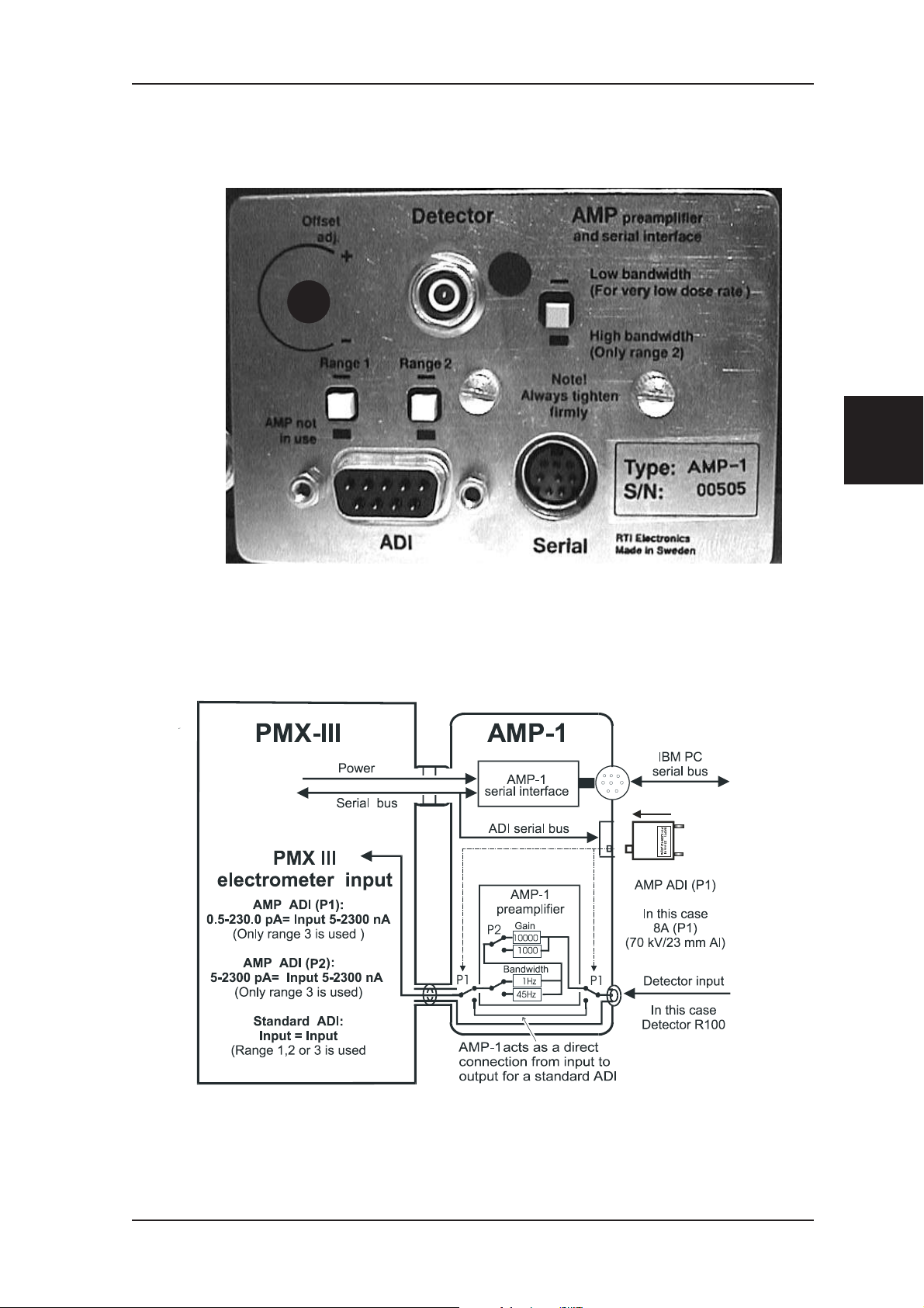
2.9 AMP-1 Front Panel
2
Chapter
2.10 Operation of Principle of the Electrometer
PMX-III Manual 1999-03/6.0B 21
Page 26

Chapter
2
Operation of Principle of the Electrometer DESCRIPTION OF PMX-III
This page is intentionally blank.
22 1999-03/6.0B PMX-III Manual
Page 27
HOW TO SET UP THE SYSTEM
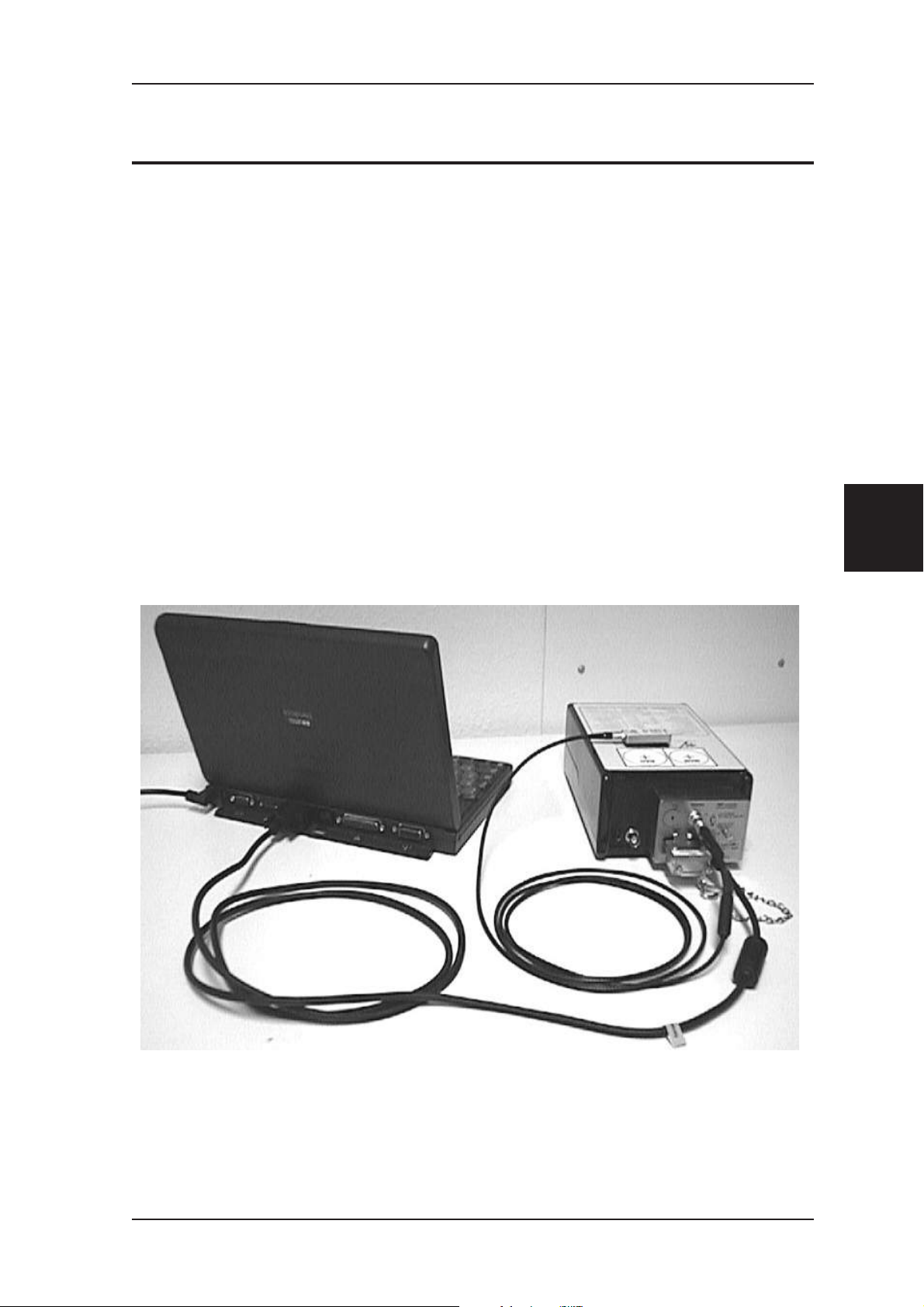
3 HOW TO SET UP THE SYSTEM
Place PMX-III in the X-ray field for multimeter measurements.
•
For dosimeter measurements place the PMX-III as convenient for you as
•
possible and use the 8 meter extension cable and the probe holder to put
the detector in the measurement field.
If a computer is used, connect the interface cable between your PMX-III
•
AMP-1 and the computer (com l or Com 2), use serial extension cable if
needed.
Connect the ADI-module and detector, use detector extension cable if
•
needed.
Connect the power supply to the BRB-1.
•
• Power on the PMX-III, start oRTIgo or follow instructions on top panel.
3
Chapter
Figure 1. Correct connection of the serial cable, the detector cable, and ADI.
PMX-III Manual 1999-03/6.0B 23
Page 28
Chapter
3
HOW TO SET UP THE SYSTEM
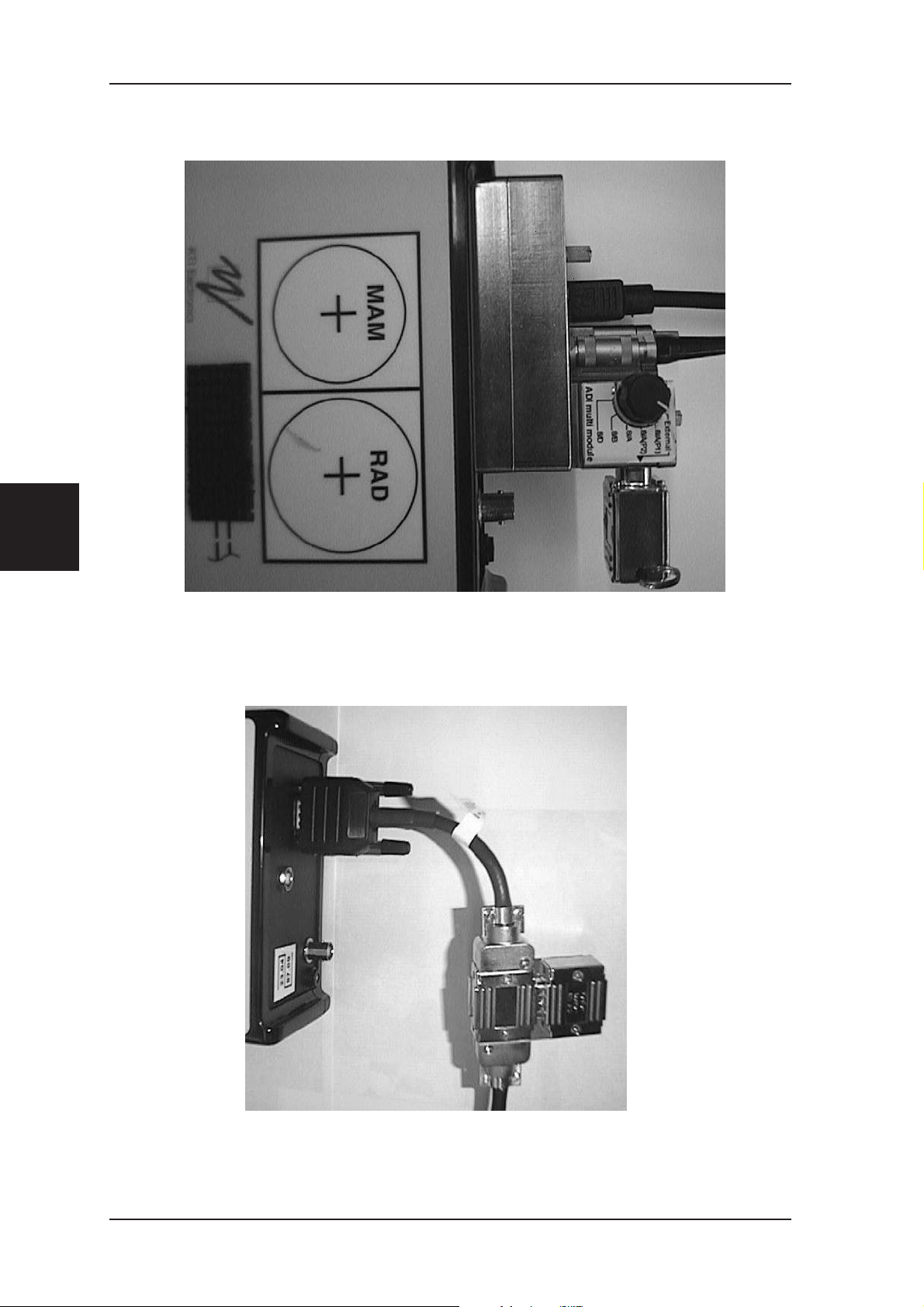
Figure 2. Detail picture of connection of the serial cable, the detector
cable, and ADI Multi module (option).
Figure 3. Correct connection of the serial cable, and ADI for the old
serial interface.
24 1999-03/6.0B PMX-III Manual
Page 29
BASIC QC MEASUREMENTS kVp and Time (Multimeter Mode)
4 BASIC QC MEASUREMENTS
4.1 kVp and Time (Multimeter Mode)
4.1.1 PARAMETER
This key selects the measuring parameter to be displayed.
Each time the key is pressed the display changes between kVp, exposure time,
dose, and dose rate.
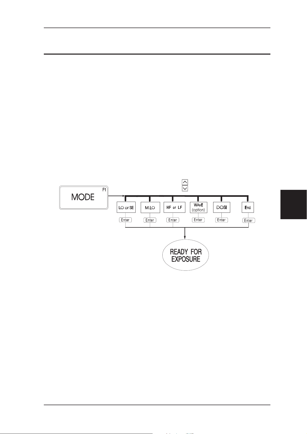
4.1.2 MODE
This key selects the type of measuring mode:
SET or LOCK mode, manual LOCK mode, LF or HF mode, waveform
analyzer , or dosimeter mode.
Chap
4.1.3 When to use SET and LOCK modes
SET basic measuring mode (>50 ms exposure times).
LOCK- kVp and time measurements for short exposure
times. (See also manual LOCK mode)
Two exposures must be done when using LOCK Mode. One to set PMX gain
and range and one to get the values.
4
Chapter
Use LOCK Mode to
•
Study the beginning of the exposure waveform using the BNC output
•
Measure exposure time by counting pulses.
PMX-III Manual 1999-03/6.0B 25
Page 30

kVp and Time (Multimeter Mode) BASIC QC MEASUREMENTS
4.1.4 When and how to use manual LOCK mode
Chapter
When it is impossible to make a set exposure because of too short
•
exposure time.
When the user wants to control how PMX-III selects kV-range and gain:
•
Press DNARR to select between:
F1:G1 to F1:G4 - F2:G1 to F2:G4
F1= kV range 45-90 kV
F2= kV range 85-155 kV
G1= Very low X-ray output
G2= Low X-ray output
G3= Average X-ray output
G4= High X-ray output
4
The electrometer always uses range rA:3 .
4.1.5 When to use LF and HF:
LF - single phase
- three phase 6-pulse
- 12-pulse, DC, and mammo units
- HF > 5 kHz and ripple less than 5 %
- Most modern DC/DC X-ray units.
HF - 0.8-5 kHz, only when ripple>5%.
The analog output bandwidth for PMX-III is 800 Hz in LF mode and 10 kHz
in HF mode.
26 1999-03/6.0B PMX-III Manual
Page 31

BASIC QC MEASUREMENTS kVp and Time (Multimeter Mode)
4.1.6 TUBE/FILTER
This button selects valid calibration tables for different tube/filter
combinations.
Up to 16 different calibration tables can be selected.
1-4 are dedicated for the diagnostic 45-155 kV range.
5-12 are dedicated for mammo use. 13-16 for CT.
Calibration table numbers which are stored into PMX-III are indicated after
the text CA in the display (Ex. CA -1). Use cursor keys to select correct
tube/filter combination from the existing calibration table. Store with the
ENTER key.
F3, F4, and F5.
Factory set function keys for direct setup of measuring conditions. The keys
can also be user defined.
y+F3
Press UPARR and while still pressing UPARR, press F3, use cursors to select
delay 0-9999 ms.
Press ENTER to store the new value.
4
Chapter
PMX-III Manual 1999-03/6.0B 27
Page 32

kVp and Time (Multimeter Mode) BASIC QC MEASUREMENTS
4.1.7 Measurement with the MAM/RAD version
Connect the dose detector/ADI module.
•
Each ADI module holds information for one beam quality only (See also
•
the “Detector Selection Guide” chapter 9 if you need additional help).
Power on PMX-III. The “DOSIMETER” indicator must be off. If the
•
indicator is on, press the MODE key and enter “MuLt”.
Choose a calibration table with the TUBE/FILTER key, or press a
•
function key to upload a setup table.
Position the sensor area (MAM or RAD) in the X-ray beam, and
•
collimate the light field.
Put the dose detector on top of the PMX-III, and add desired additional
•
filtration.
Chapter
4
• Set desired generator values and make an exposure.
• Read the measured values from the display.
• After the results have stopped flashing, and the character “c” has
disappeared, PMX-III is ready for another exposure.
• Press the PARAMETER key to alter between kVp, exposure time, dose,
dose rate, or light.
28 1999-03/6.0B PMX-III Manual
Page 33
BASIC QC MEASUREMENTS kVp and Time (Multimeter Mode)
4.1.8 Default values for F3-F5 (MAM/RAD version)
F3 Setup table #1; (CA:1 diagnostic)
W/Al 3.0 mm, 45 - 155 kV
F4 Setup table #4; (CA:5 mammo)
Mo/Mo 30 um, 23 - 35 kV)
F5 Setup table #5; (CA:6 mammo)
Mo/Al 2.0 mm, 30 - 46 kV
Setup table #1 is always uploaded when the
PMX-III is powered on.
4.1.9 CT kVp Measurement with the CT/RAD version
Power on PMX-III. The “DOSIMETER” indicator must be off. If the
•
indicator is on, press the MODE key and enter “MuLt”.
• Choose a calibration table with the TUBE/FILTER key, or press a
function key to upload a setup table.
• Press F4 or F5 according to the table below:
• F4 Setup table #13; (CA:13 CT without comp.filter)
W/see calibration record,75-145 kV
• F5 Setup table #14; (CA:14 CT with comp.filter)
W/see calibration record, 75-145 kV
4
Chapter
PMX-III Manual 1999-03/6.0B 29
Page 34

kVp and Time (Multimeter Mode) BASIC QC MEASUREMENTS
Open the beam width to 10 mm. Use the patient positioning light to
•
align the CT sensor area horisontally within the beam.
Disable the motion of the tube and table. Place the tube in the top
•
position.
Make the exposure, both kVp and time will be displayed after the
•
exposure is finished. Use the PARAMETER key to select kVp and time.
Make corrections of the kVp value for the filtration dependence if
•
needed,
Consult the PMX-III reference manual, Appendix E for more information
how to correct for filtration depencence and how to make kVp measurements
with rotating CT units and oRTIgo
Chapter
4
30 1999-03/6.0B PMX-III Manual
Page 35

BASIC QC MEASUREMENTS Dose and Dose Rate (Dosimeter Mode)
4.2 Dose and Dose Rate (Dosimeter Mode)
PMX-III is normally supplied with two small durable and accurate solid state
detectors for X-ray and light measurements, and a number of ADI modules.
(See the “Detector Selection Guide; Chapter 9” if you need additional help.)
In dosimeter mode dose and dose rate are measured simultaneously. Press the
DOSE key and the measured dose value is displayed. Press the RATE key
and the measured dose rate is displayed. Rate is indicated on the display with
a “:” sign.
MODE The MODE key is used to select manual LOCK,
free run, or trig level, or return to multimeter
mode.
4
Chapter
PMX-III Manual 1999-03/6.0B 31
Page 36

Dose and Dose Rate (Dosimeter Mode) BASIC QC MEASUREMENTS
4.2.1 When and How to Use Manual LOCK Mode
Press DNARR to manually select electrometer range if manual LOCK mode
is selected:
RA:1 This is the most sensitive range for low dose rate
measurements.
RA:2 Middle range.
Chapter
4
RA:3 This range should be used for high dose rate mea
surements.
It is recommended to use the manual LOCK mode when the exposure time is
less than 50 ms.
Press MODE , select Auto to select auto range.
4.2.2 How to Use Free Run/Trig Mode
In the free run mode no trig levels exist. This makes it possible to measure
down to zero signal in the display. In trig run mode, measured dose rate value
is started to be displayed when the signal is above a set trig level determined
by the selected ADI. Please note that PMX-III is not powered down
automatically when “Free run” is activated.
-
32 1999-03/6.0B PMX-III Manual
Page 37

BASIC QC MEASUREMENTS Dose and Dose Rate (Dosimeter Mode)
4.2.3 Active Keys
DOSE Press to read measured dose in specified
dose unit.Press again to display dose unit.
RATE Press to read measured dose rate value
in specified dose unit.
Press again to display dose unit.
RESET Press <1 s to reset display to zero.
Press >1 s for internal zero-adjustment.
The ADI code X.-Y- where
X= Detector identification 1, 2, 3 .6.7.8 .. and
Y= Beam quality A, b, C, d, U,Y.
is displayed for 1 s to indicate valid ADI.
The ADI code for AMP is XY.PZ where
X and Y is defined as above . P indicate AMP-1
Z =1 for range 1 , Z=2 for range 2
y+MODE Press to normalize the display value to a prede-
fined value. Can be used to calculate a ratio between two detector signals. Abort normalize mode
by pressing y+MODE again.
y+RESET Press to toggle between manual and auto-
reset modes.
Manual: Dose values are accumu
lated
Auto: Previous dose value is cleared
y+DOSE Press to hold display value. Abort by pressing
y+DOSE again.
4
Chapter
-
PMX-III Manual 1999-03/6.0B 33
Page 38

Dose and Dose Rate (Dosimeter Mode) BASIC QC MEASUREMENTS
y+RATE Press to select the dose/frame menu:
Use the cursor keys to select:
1.5-63.5
Chapter
4
OFF Normal dose and dose rate measurement
Fr Selects the frame mode.
Press ENTER and current number of frames during the exposure is shown in the display.
Use the cursor keys to select a new value.
Press ENTER to store the new value,measuring
mode is activated again.
The measured and displayed dose is divided with the number of frames.
Fr.: Selects the frames/second mode.
Press ENTER and current number of frames dur
ing one second is shown in the display.
Use the cursor keys to select a new value.
Press ENTER to store the new value,
measuring mode is activated again.
-
The measured and displayed dose rate is divided with the number of frames/s.
It is recommended to use the manual LOCK mode when using the frame
mode.
An alternative method is to use the waveform analyzer and oRTIgo. The number of
pulses, number of frames/s or Hz, and dose/frame are automatically calculated
from the stored dose rate wave form.
34 1999-03/6.0B PMX-III Manual
Page 39

BASIC QC MEASUREMENTS Dose and Dose Rate (Dosimeter Mode)
4.2.4 How to Make a Measurement
Connect the dose detector/ADI module.
•
Each ADI module holds information for one beam quality only.
Power on PMX-III. The “DOSIMETER” indicator must be on. If the
•
indicator is off, press the MODE key, scroll with the cursor keys and
select “dOSI” with the ENTER key.
Position the dose detector in the X-ray beam.
•
Set desired generator values and make an exposure.
•
• Read measured values on the display. Both dose rate and dose value are
stored after the exposure.
4
Chapter
PMX-III Manual 1999-03/6.0B 35
Page 40

The Waveform Analyzer BASIC QC MEASUREMENTS
4.3 The Waveform Analyzer
It is strongly recommended to use oRTIgo to collect waveform if possible
since it is much easier to handle. If used without computer it is recommended
to read sections 6.1 to 6.3 in the reference manual at least once before using
the analyzer:
Chapter
Connect a BNC cable between the connector on the rear of the PMX-III
•
and your oscilloscope (amplification: 0.5 V/div, time: 5 ms/div).
Use the MODE key to enter the mode menu and be able to switch the
•
waveform analyzer on and off.
The waveform analyzer has three main levels indicated on the display:
•
“Set”:
All PMX-III keys are valid. The PMX-III waits for an exposure
to adjust gain and filter to current generator settings.
4
• “SAMP”:
Waiting for an exposure. Gain and filter adjustment are set from an
earlier exposure or by the user if manual lock mode is selected.
The PMX-III samples the detector to be able to measure the initial part
of the exposure.
“PA:1":
Sending sampled kV and radiation waveforms to the oscilloscope.
“RY:1”:
Sending sampled electrometer and radiation waveforms to the
oscilloscope
•
Make exposures, and the PMX-III automatically adapts to the
measurement situation.
•
Use the:
-PARAMETER key to toggle between kV and radiation or electrometer
waveforms.
-cursor keys to select different memory parts of the measured exposure.
-F3 key to calibrate the kV or electrometer rate waveform on the
oscilloscope.
-ENTER key to go to “SEt” level.
36 1999-03/6.0B PMX-III Manual
Page 41

BASIC QC MEASUREMENTS The Waveform Analyzer
Please consult Section 6.3.2 and 6.5 in the reference manual to use the
programming features.
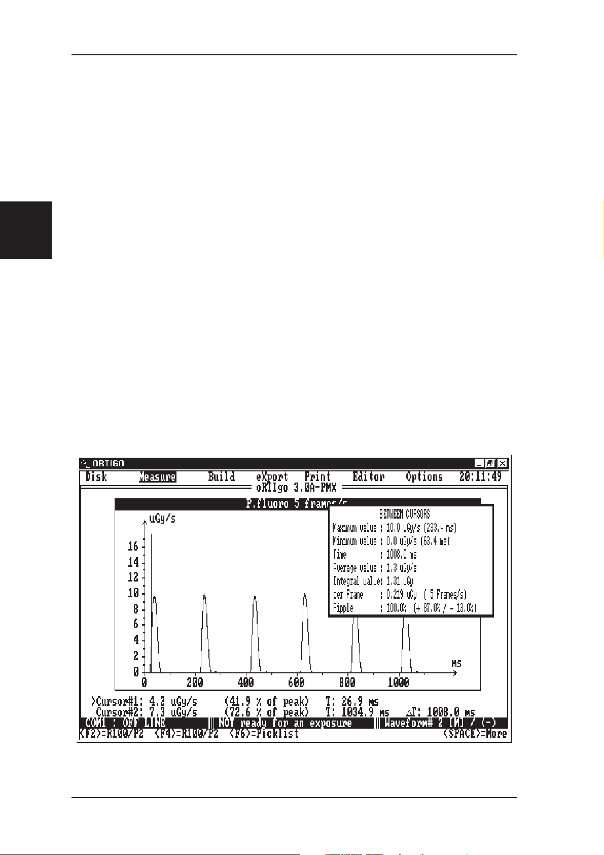
4.3.1 Examples of waveforms
Dose rate response from a dental unit at two bandwidth
60 kV, 3 mA, 23 mm Al, SSD=30cm, 8/A(P2)
45 Hz and 1 Hz are selected using the AMP-1 filter knob.
4
Chapter
Upper: Dental kV, compressed mode
Lower: Dental output, simultaneously sampled
PMX-III/PH Manual 1999-03/6.0B 37
Page 42

The Waveform Analyzer BASIC QC MEASUREMENTS
4.3.2 Waveform flowchart
Sa mp lin g ra te
Chapter
4
The flo w c ha rt is va lid
for PMX-III firmware 6.0
Wa v f lo w 4 . c d r
38 1999-03/6.0B PMX-III/PH Manual
Page 43

BASIC QC MEASUREMENTS Using preamplifier AMP-1
4.4 Using preamplifier AMP-1
AMP-1 consists of a preamplifier
for the PMX-III electrometer and a
serial interface. See Chapter 2 for
an overview of the AMP-1
functions.
AMP-1 makes it possible to
increase the sensitivity 100 times
when used with PMX-III. This
sensitivity is needed for acceptance
test and adjustment of modern
Image Intensifier systems.
AMP-1 should only be used with the PMX-III in Dosimeter mode.
The AMP-1 is specially designed to measure the very low entrance dose rate
levels to an Image Intensifier (II). An optimised range for II of 0.030 µGy/s to
about 46 µGy/s is obtained when the detector R25/R100 is used together with
AMP-1. The preamplifier is simply “piggy backed” directly on the PMX-III
back panel, eliminating connecting cables. The AMP-1 is powered by the
PMX-III.
Furthermore there is no need to disconnect the AMP-1 and the detector from
PMX-III since the AMP-1 only is activated when a special made
AMP-1 ADI is used.
The special AMP-1 ADI (Automatic Detector Identification) combines the
features of storing the detector data in use into the ADI and simultaneously
activate and select range of the AMP-1. The AMP-1 has two measurement
ranges, P1 and P2.
AMP-1 has a built-in second order low-pass filter with two ranges,
DC-1 Hz and DC-45 Hz.
4
Chapter
The special ADI connected to the AMP-1 makes it possible to read directly in
µGy/s (or µR/s) and µGy (µR) on the display depending on AMP-1 range and
detector. The II dose rate waveform can also be collected and displayed using
the oRTIgo wave form analyser or with an oscilloscope.
A handy method to adjust the II entrance dose rate level (typically 0.10-0.50
µGy/s) is to look at the dose rate level with an oscilloscope. The scale factor
is 1 µGy/s / V, if the AMP-1 and R100 is used and the oscilloscope is
connected to PMX-III BNC output.
PMX-III Manual 1999-03/6.0B 39
Page 44

Using preamplifier AMP-1 BASIC QC MEASUREMENTS
Example:
The picture below shows a measurement with a dose rate of 0.13 µGy/s
ocilloscope settings: 0.05 µGy/s /div. 1 s/div.
Chapter
4
Using oRTIgo a certain portion of the dose rate waveform can be selected
using the radiation waveform as reference. This part of the dose rate
waveform is then integrated and the dose/frame, dose rate value and number
of frames/s value is automatically calculated and displayed.
40 1999-03/6.0B PMX-III Manual
Page 45

BASIC QC MEASUREMENTS Measurements with the AMP-1
4.5 Measurements with the AMP-1
4.5.1 General
It is recommended that only dosimeter mode is used with the AMP-1.
Select reading in dose rate by pressing the RATE knob.
Be aware that the limited bandwidth of 1 Hz is optimised for Image
Intensifier measurements measuring the dose rate signal. If pulsed
fluoroscopy should be measured you must select higher bandwidth. Select
range 2 and 45 Hz or deactivate the AMP-1 to get 700 Hz bandwidth to be
able to follow the individual pulses.
The PMX-III starts to measure when the dose rate signal is greater than
approximately 0.050 µGy/s when using the AMP-1 8/A(P1) ADI
(0.030-4.600 µGy/s for R100).
Select “Free” run mode if the AMP-1 should start to measure all the way from
zero.
For short exposure times or pulsed radioscopy please deactivate the AMP-1 by
selecting the appropriate ADI and select multimeter mode or use the waveform
analyzer to be able to measure the individual dose rate pulses.
When selecting multimeter mode you should and must “gate” the dose rate signal
by using the PMX-III kV detector as a trigger. This method makes the
measurement easy to do. You can even combine the dose rate and dose reading with
kVp and exposure time measurements.
4
Chapter
PMX-III Manual 1999-03/6.0B 41
Page 46
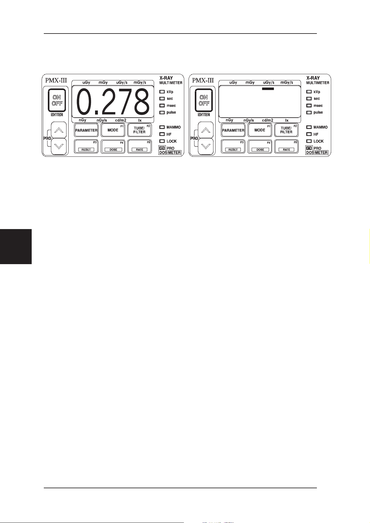
Measurements with the AMP-1 BASIC QC MEASUREMENTS
4.5.2 Detector Range and Identification Codes
On the above display the colon indicates that rate mode is selected.
As long as the RATE key is pressed, the sign above µGy/s is shown to
indicate that the unit is µGy/s. The reading is 0.278 µGy/s.
The measuring range and unit is indicated on the ADI.
Chapter
4
An identification code for the selected conversion factor is shown during
approximately one second after reset and zero adjust.
X.-Y- Standard ADI, for detector X and beam quality Y.
XY.PZ AMP ADI, for detector X, beam quality Y,
range Z (1 or 2).
42 1999-03/6.0B PMX-III Manual
Page 47

SERVICE / MAINTENANCE Introduction
5 SERVICE / MAINTENANCE
5.1 Introduction
The default function of PMX-III was earlier to start up with Multimeter or
Dosimeter mode, depending on the mode used when it was powered off. This
is sometimes inconvenient, especially when having specific written
instructions for certain measurements.
You can now program the PMX-III to start up in either Multimeter or
Dosimeter mode. You activate this function by pressing the MODE and
ENTER key when choosing the measuring mode you want to be default after
power on. It is done in the following way:
Activate the measuring mode, Multimeter or Dosimeter, you don’t want to have as
•
default. Use the MODE menu if you have to change measuring mode.
• Press MODE to activate the MODE menu.
• Move to the entry corresponding to the mode you want to have as default, i.e. “Mult”
or “dOSI".
• While keeping the MODE key pressed, press the ENTER key.
• Release both keys.
The PMX-III will now start up with the measuring mode you selected.
To disable the above described function:
• Press the MODE key.
•
Move to the entry End.
•
While pressing the MODE key, press Enter.
5.1.1 New Version of Firmware for PMX-III.
•
Automatically selects dose rate when ADI 7A(P1) or 7A(P2) is detected
•
All dose rate measurements with ADI 7A(P1) and 7A(P2) will be displayed in the
same unit (µGy/sec or µR/sec )
•
The measured dose rate is "freezed" in the display until a new exposure starts or
reset is pressed (not in Free Run mode, without trig level)
5
Chapter
•
Possibility to select half of frame number, for example 12.5 (consequently the
maximum value will be 63.5 instead of 125)
•
The Hi-YES-Lo message related to the offset adjustment (when AD 7A(P1) is used)
is removed (see: "Offset potentiometer" chapter 2)
PMX-III Manual 1999-03/6.0B 43
Page 48

Introduction SERVICE / MAINTENANCE
5.1.2 Extension Cable.
An extension cable (8m)
connected to the
R25/R100 probe enables
the engineer to position
the PMX-III at a conve
nient place (i.e. near to
control desk in control
room of the PMS system).
This makes PMX-III
frontpanel operation and
reading of the display eas
ier during testing.
Furthermore the engineers
radiation load is kept as
low as possible. Avoid
work near the radiation field.
-
-
Chapter
5
5.1.3 Probe Holder.
The R25/ R100 probe is
attached to the probe
holder. This support
makes positioning of the
probe in the X-ray beam
much more easy (i.e. in
Scopomat). It also prevents the probe to rotate
by the force of the cable
which can result in consid
erable measuring inaccuracy.
-
5.1.4 ADIs Removed from Detector Cables.
Since there are too many ADIs connected to the cable-chain of the detector
cables (both R100 and L100) they are removed and stored in a separate
storage area in the case.
5.1.5 Maintenance.
In order to prevent damage
to the probes during trans
port a protection cover is
supplied with the
R25/R100 dose probe and
L100 light probe.
44 1999-03/6.0B PMX-III Manual
-
Page 49

SERVICE / MAINTENANCE Entrance Dose Rate Measurements
5.2 Entrance Dose Rate Measurements
5.2.1 Very Low Entrance Dose Rate to an Image Intensifier
See also on top of PMX-III for a very short instructions
Put 20 mm Al or equivalent copper filter (appr. 1.4 -2.1 mm Cu plate) to
•
simulate a patient thickness. Use the probe holder to fixate the R100 so
it is easy to move it over the II input area. Place it on the II so that is not
affecting the feedback system. As a guideline, do not place the detector
in the centre of the field, rather somewhere near a circle with half the the
diameter of the field diameter.
Use the EXT-1 extension cable if needed.
•
Select high dose rate bandwidth with the little tiny red button on the rear
•
panel (the button should be “out”
• For continuos fluoro select ADI 8/A (P1) The range is now 0,030-4,600
µGy/s and the reading is directly in µGy/s, on the PMX-III.
For pulsed fluoro measurements select 8/A (P2) The range is now
0,1-46 µGy/s range instead and also the higher bandwidth (DC to 45
Hz).
• Power on PMX-III and select free run mode (see section 2.3), then select
RATE. By selecting free run mode PMX-III deactivates the trig level so
the user is able to measure all the way down to zero .
•
Verify by pressing RESET that the correct ADI is selected.
•
Start the fluoro exposure. The dose rate is updated on the display during
the exposure. You can freeze the display during the measurements using
the hold mode, see Chapter 4 but since the display values are stored after
the exposure both for dose rate and dose there are normally no need to
use this function anymore.
Pressing the RATE button during or after the measurements displays the
measuring unit.
5
Chapter
Note:
Other detectors and measuring units are also supported.
In this chapter the dose detector R100 and use of Gray units have been used.
See Chapter 9 and the Shortform Detector Selection Guide for use of other units.
PMX-III Manual 1999-03/6.0B 45
Page 50

Entrance Dose Rate Measurements SERVICE / MAINTENANCE
Hints:If the dose rate output also needs to be monitored during adjustment, please
connect an oscilloscope to the PMX-III BNC connector. Select 100 mV/Div. and
1s/Div. on the scope. A change of the dose rate of 0.1µGy/s is then equal to 1 Div.
on the y-axis. The bandwidth is approximately 1 Hz or 45 Hz.
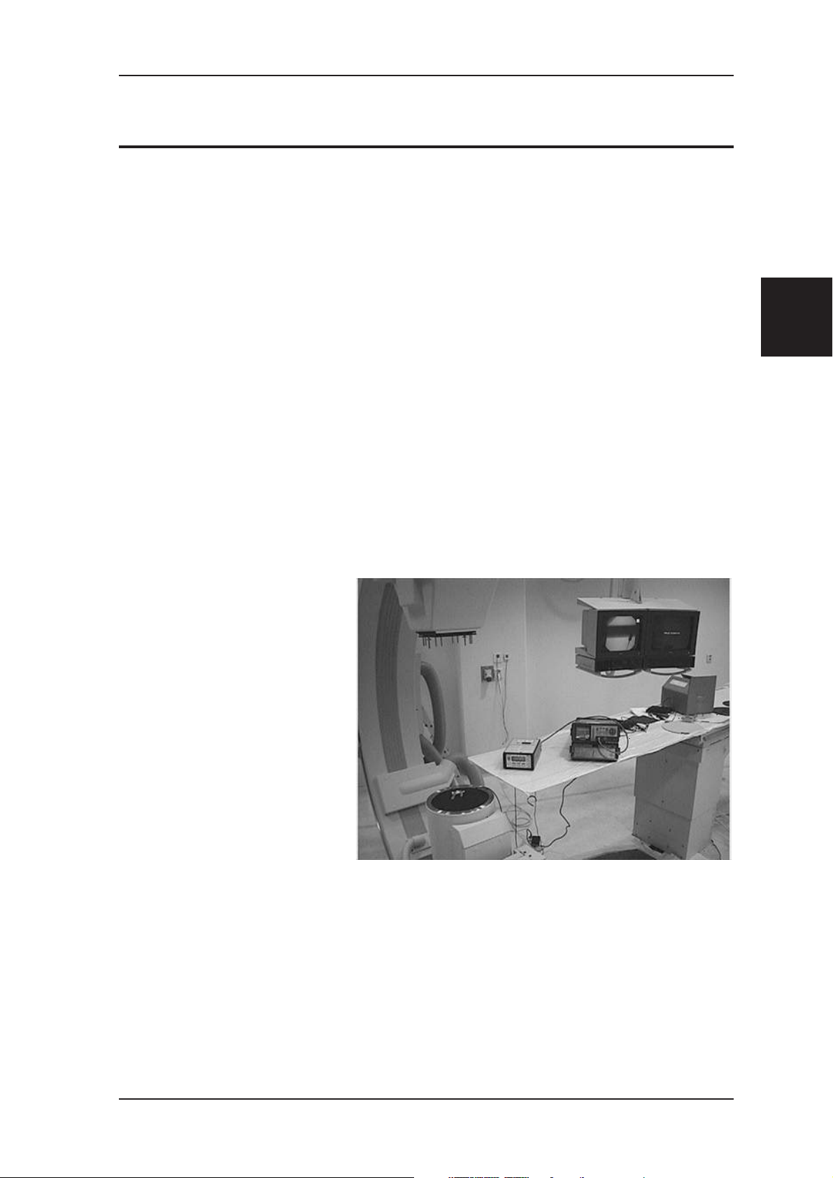
Chapter
5
Dose rate measurement on II fluoro system with PMX-III/AMP-1.
46 1999-03/6.0B PMX-III Manual
Page 51

SERVICE / MAINTENANCE Entrance Dose Rate Measurements
5.2.2 Hints
Use the probe holder
•
together with R25/R100 to
be able to place the detector
in a suitable place on the II
input screen. By observing
the dose rate measured
during slow movement of the
detector above the II you can
check if the detector is
altering the feedback system
or not.
Use the “free” run mode in
•
dosimeter mode to deactivate
the internal trig level. This
makes it possible to measure
linearly all the way down to
The R100 on rod in image intensifier field.
the display reading will not suddenly change to zero or freeze.
zero in the display.
It is therefore easier to adjust
small dose rate values since
• If no dose rate can be measured, please check that the current is greater than 0.05
µGy/s or select “free” run mode.
• The AMP-1 can be mounted all the time on the PMX-III. The AMP-1 is only
activated when the special ADI that “power on” the AMP-1 mechanically is used.
When a normal ADI is used the current signal is passed directly to the PMX-III
electrometer input without using AMP-1’s signal amplification.
•
Use the 8 meter extension cable EXT-1 to be able to place PMX-III in the control
room for easy readout and change of ADI.
•
Use the BRB-1 and AC/DC adapter to avoid battery drain.
•
Select “free” run mode to avoid PMX-III to power off.
It is recommended to use BRB-1 in this situation.
•
Use High bandwidth (45 Hz)allways if possible .
•
Test have been done with R100 8A(P2) 45 Hz on pulsed fluoro/dental system
indicating that measurements with pulse rate of up to approximately 30 pulses/s can
be measured.
•
The AMP-1 ADI automatically selects gain 3 on PMX-III electrometer.
This is indicated by the “Manual Lock” LED. Trying to use gain 1 or gain 2 easily
result in a"HI.Si" message.
5
Chapter
•
If problems should appear with the serial communication transfer, please check that
the PMX-III BRB power supply and the computer power supply is connected to the
same power outlet.
PMX-III Manual 1999-03/6.0B 47
Page 52

Fluoroscopy low mA SERVICE / MAINTENANCE
5.2.3 Example of Dose Rate Waveforms
An oscilloscope was connected to the analog output of the PMX-III.
The external
detector R100 was
placed in the X-ray
field so dose rate
waveform could be
collected using the
PMX-III waveform
analyzer. Only the
dose rate waveform
was displayed on the
oscilloscope. 100
nGy/s was
measured.
(50 nGy/s/div and
1s/div)
Chapter
5
5.3 Fluoroscopy low mA
5.3.1 II-Entrance Dose Rate (µGy/s)
• Connect dose detector R100 and ADI 8/A(P1) to the input on the rear
panel of the PMX . Make sure that the range 1 or 2 switches are
correctly depressed.
•
Select high bandwidth with tiny red button (pull out) on rear panel.
•
Add 1.5 mm Cu or 20 mm Al filtration.
•
Power on the PMX and wait until the internal checks are completed.
•
The dosimeter LED should be on now and PMX-III is ready to measure
dose rate. A “:” in the middle of the display indicates that dose rate is
selected (1).
•
Press select Free run with the cursor keys, and press Enter to
activate “Free”run mode.
•
Give fluoroscopy command, wait for stable reading.
•
Read desired value during or after the exposure
•
The unit of measurement is shown when pressing or .
48 1999-03/6.0B PMX-III Manual
(2)
Page 53

SERVICE / MAINTENANCE Exposure Dose
(1) The lower third dot indicates the deciml dot !
(2) y+RESET
Press to toggle between manual and auto reset modes.
Manual: Dose values are accumulated
Auto: Previous dose value is cleared
y+DOSE
Press to hold display value. Abort by pressing y+DOSE again.
Note: If the display indicates a dash (-) or (Hi Si) ,then press reset longer then 1
second until c appears and now PMX corrects for internal zero-adjustment., It is
normal that the display still indicates a dash(-) after reset sometimes if the drift is
slightly negative.
5.4 Exposure Dose
5.4.1 Fluorography and Radiography
• Connect dose detector R100 and ADI for:
Falling load ADI: 8A
Fixed current ADI: 8A(P2) (1)
• Select high bandwidth by releasing the tiny red button on the rear
panel.
• Add 1.5 mm Cu or 20 mm Al filtration.
•
Select an appropriate exposure time >=50 ms (2)
•
Power on the PMX and wait until the internal checks are completed,
this means the dosimeter LED is on.
•
Make a single exposure
Both the measured dose and dose rate value have been collected and are
available on the display. Use or to move between
measured rate or dose value. By holding down the same key the unit of
measurement is indicated.
5
Chapter
(1) In case of Hi Si display code, take the less sensitive ADI 8A
(2) If exposure time is less than 50 ms, program manual lock mode. (Section 4.2)
PMX-III Manual 1999-03/6.0B 49
Page 54

Measurement of kVp SERVICE / MAINTENANCE
5.5 Measurement of kVp
5.5.1 Long Exposure time, Skin Dose, and Dose Rate
(SET MODE)
Connect dose detector R25 and ADI 7/B (this means no extra filtration
•
in the beam) to the input on the rear panel of the PMX .
Power on the PMX and wait until the internal checks are completed, this
•
means the character “c” has disappeared.
If dosimeter LED stays on after power on, press Mode. The display
•
shows “M.LO”. Select “MuLt” with the cursor keys and press Enter to
activate multi meter mode.
Place dose detector on the velcro strip on top of the PMX and position it
•
in the beam.
Chapter
5
• Select for the RAD sensor area a beam quality of 3 mm( ADI:8/B)
• Set kVp, mA.
• Exposure time (1) may be as low as:
50 ms for good kV measurement.
10 ms for good exposure time measurement.
• Make an exposure.
• Read the values which are displayed automatically in the following
sequence:
kVp
time
unit for dose(rate)
skin-dose(rate)
“c” indicating auto reset performed after each exposure
After this the display returns to one of the values measured .
Press PARAMETER button to scroll measured values.
Note: collimate X-ray field to protect the AMP-1 module at rear of PMX against
direct radiation! It is important to irradiate the complete RAD field on top of the
PMX.
Note: If the total filtration is not 3.0 mm Al, measured kV should be corrected to
achieve maximal accuracy, see chapter 7.
50 1999-03/6.0B PMX-III Manual
Page 55

SERVICE / MAINTENANCE Measurement of kVp
5.5.2 Short Exposure Time, Skin Dose and Dose Rate
(MANUAL LOCK MODE)
Select manual LOCK mode, in
•
this mode the internal filter and
gain range combination are user
selectable.
Make an exposure.
•
Exposure time
•
may be as low
(1)
as:
3 ms for good kV measurement.
0.3 ms for good exposure time
measurement.
In case of over- or under flow the
•
default filter/gain combination
for PMX is not correct.
• Press DNARR to select between:
F1:G1 to F1:G4
F2:G1 to F2:G4
F1= kV range 45-90 kV
F2= kV range 85-155 kV
G1= Very low X-ray output
G2= Low X-ray output
G3= Average X-ray output
G4= High X-ray output
5
Chapter
The electrometer always uses range rA:3 .
(1) Exposure times are specified for HF and DC generators, for 12 pulse (or
lower) generator types see Reference manual page 7-4
If you only want to use the PMX-III as an exposure timer, you can select a display
mode (disp) and parameter (Par) that only display the exposure time after each
exposure, see reference manual chapter 4 section 4.9.4.
PMX-III Manual 1999-03/6.0B 51
.
Page 56

Light Measurements, Detector and Adapters SERVICE / MAINTENANCE
5.6 Light Measurements, Detector and Adapters
5.6.1 Introduction
For more general information about light measurements a separate L100
manual can be ordered from RTI Electronics AB
L100
The L100 detector is the fundamental part of the light meter system from RTI
Electronics AB. On top of the actual detector a filter house is attached. This is
shown in below. The filter house contains the CIE filter that makes the
silicon chip have the same response as the human eye. The purpose of the
filter house is also to fit the different adapters that make the L100 measure the
desired quantity. The actual L100 without any adapters is not calibrated for
any quantity.
Chapter
5
The basic L100 detector which include the CIE filter house
Monitor Adapter
The monitor adapter is intended for luminance measurements on CRTs and
film viewing boxes, i.e. to measure cd/m², and it is referenced to as L100-M.
It consists of two parts: a metal tube with a light shutter and an ambient light
shield made of rubber. This is shown on next page. A luminance meter must
have a limited field of view. In the case of L100-M this is accomplished by
pressing the tube against the surface to be measured.
52 1999-03/6.0B PMX-III Manual
Page 57

SERVICE / MAINTENANCE Light Measurements, Detector and Adapters
The purpose of the ambient light shield is to prevent non-wanted light to
interfere with the measurements. This could otherwise be a problem when
measuring on not so bright sources like e.g. a CRT. Without the ambient light
shield non-wanted light, e.g. from the room, would be reflected via the glass
surface of the CRT and would be added to the measured light. A smaller
shield is also included to make the easier to position the monitor when the
ambient light level
is not a big error
source.This is also a
part of the reason
why
RTI Electronics AB
has chosen not to
design a traditional
luminance meter,
with optics that let
you measure at a
distance. Such a
measurement would
obviously be a
measurement of not
only the source
itself but also of the
ambient light
reflected by e.g. the
The monitor adapter with light shutter and ambient light shield..
glass surface of the
CRT.
5
Chapter
Lux Adapter
To measure illuminance the detector must be able to collect light from every
direction in a half sphere. The contribution from an incidence light beam must
follow the cosine function. This is quite natural if we consider how we
apprehend the surface of a spot on e.g. a desk. Seen from above at an
incidence angle of 0° the projected area of the spot is the same as the real one.
When we increase the angle of incidence to 60° the projected area decreases
by a factor of 0,5, just like cosine 60° equals 0,5. When we have increased the
angle of incidence to 90° we of course cannot see the spot, just as cosine 90°
equals 0.
In theory this sounds easy but in practice there are a few things to consider
when designing a lux detector.
53 1999-03/6.0B PMX-III Manual
Page 58

Chapter
5
Light Measurements, Detector and Adapters SERVICE / MAINTENANCE
First: The surface of the silicon chip will always be shiny. This means
•
that light that hits the detector from a very large angle of incidence will
be reflected by the surface of the silicon chip, thus neglecting the cosine
function.
Second: The actual silicon chip can in most cases not be placed at the
•
surface of the detector. An example of this is the L100 with its CIE
filter.
The solution to these problems is the lux adapter, see figure below. The white
plastic inside the aluminium is called a cosine diffuser.
The surface of the
cosine diffuser is, as
the name implies,
diffuse. Thus
preventing light with a
large angle of
incidence from being
reflected by the
surface. The cosine
diffuser also leads the
light down to the
silicon chip, more or
less in the same way as
an optical fibre can
The Lux adapter with its cosine diffuser
lead light. The lux
adapter is referenced to
as L100-L.
Collimator Adapter
The collimator adapter is a piece of plastic witha1mmhole, and it is
referenced to as L100-C. Its purpose is to allow you to check the contrast ratio
of the edge of the collimator light field. You measure the “light level” just
inside the edge of the light field and divide this value with the “light level”
outside the edge of the light field. This ratio should be sufficiently large.
Since this is a relative measurement there is no need to define what the
quantity “light level” means. You simply measure the current that the L100-C
produces. This also means that there is no need for a calibration of the
collimator adapter.
Contact RTI Electronics AB for further information about the collimator
adapter.
PMX-III Manual 1999-03/6.0B 54
Page 59

SERVICE / MAINTENANCE Light Measurements, Detector and Adapters
5.6.2 Measurement of Luminance (cd/m²)
Connecting the L100-M to the PMX-III
Follow these steps to prepare a measurement.
If it is not already done, attach the monitor adapter tube to the detector
•
housing. It is important that the monitor adapter is pressed all way down
in the detector housing when the screw fixate the tube.
Connect the light detector L100-M to the input on the rear panel of the
•
PMX-III.
Connect the Monitor Adapter ADI module marked 6/U to the connector
•
on the rear panel of the PMX-III
Power on the PMX-III and select DOSIMETER mode, then choose
•
RATE mode. That is normally done automatically for firmware 6.0 and
later.
Make an Reset
•
You have to perform a reset before you can start to measure.
It is VERY IMPORTANT that no light reaches the detector during the
reset procedure. To ensure that the instrument is reset while the detector
is held in complete darkness you must press the light detector to a
completely black surface, e.g. the surface of the ambient light shield,
while pressing the reset key on the instrument.
With the new monitor adapter with light shutter this is a easy task since
the monitor adapter signal is zero until the shutter knob is pressed down.
To perform a reset (actually a zero level adjustment) on the PMX-III you
have to:
•
Press the reset key and keep it pressed until the character “c” is shown
on the display.
•
Wait until the character “c” has disappeared.
•
Start to measure
Move the light detector to the measuring point and open the shutter by
pressing the knob to stop, hold to collect a light value.
After you have released the knob, the PMX-III is stored the value in the
display until next measurement.
5
Chapter
55 1999-03/6.0B PMX-III Manual
Page 60

Light Measurements, Detector and Adapters SERVICE / MAINTENANCE
5.6.3 Measurements on CRTs and Film Viewing Boxes
Attach the ambient light shield to the monitor adapter. You can select
between a small and big shield. Place the light detector on the CRT or the
film viewing box. Make sure the ambient light shield is held flat on to the
surface to prevent ambient light from reaching the detector. Press and hold the
shutter knob. Read the value on the display of the instrument. Two sample
measurements are shown in below.
Chapter
5
Checking the luminance of a
monitor, in this case different
grey-level areas.
SMPTE Test Pattern
A common test pattern used
when testing CRT is the test
pattern specified by the Society
of Motion Picture and
Television Engineers, SMPTE.
This test pattern has, among
other features, 11 different areas
of grey-scale intensity, ranging
from0%to100%.
PMX-III Manual 1999-03/6.0B 56
Page 61

SERVICE / MAINTENANCE Light Measurements, Detector and Adapters
When measuring on these different grey-scale areas you should have in mind
that the luminance of an area NOT is proportional to its grey-scale value.
Instead the luminance (L) is related to the grey-scale level (G) by:
L ∝ G
γ
(Equation 1 )
Equation is equivalent to:
log(L) = γ log(G) + C (Equation 2 )
In equation 2, C is a constant and γ is the gamma value of the monitor that
characterises the relationship between luminance and grey-scale value.
5.6.4 Ambient Light and Other Sources of Error
As mentioned above ambient light will strongly affect the measurement if it is
not taken care of in an appropriate way. To examine how much the ambient
light effects the measurements you could perform a simple experiment and
measure without the ambient light shield. Measure on a CRT that is
completely black, i.e. not powered on, and compare the result with
measurements performed with the ambient light shield attached. Also
measure with and without reduced room illumination. You will notice that the
values achieved without the ambient light shield and with normal room
illumination differ considerably from the ideal value. Imagine the percentage
error you would achieve if you were to measure in this way on the 10 %
grey-scale area!
5
Chapter
Other sources of error are fingerprints and dust on the CRT. Investigations
have shown that these smudges can decrease the luminance by as much as
10 %.
If the CRT is not sufficiently warmed up the luminance can vary during the
measurements. Some monitors need several hours to stabilise. Even if the
monitor has stabilised its output luminance will vary over different areas of
the surface. To exclude this error source from your grey-scale measurements
you can perform the measurements from the same location on the screen.
Zoom the test pattern as large as possible and pan the selected grey-scale area
to the centre of the screen. If necessary you can mark the place to put the
ambient light shield with a piece of adhesive tape. The tape must of course be
placed in such a way that it does not affect the measurements.
57 1999-03/6.0B PMX-III Manual
Page 62

Light Measurements, Detector and Adapters SERVICE / MAINTENANCE
Chapter
5
Example of very compact monitor test system based on oRTIgo.
58 1999-03/6.0B PMX-III Manual
Page 63

SERVICE / MAINTENANCE Light Measurements, Detector and Adapters
5.7.3
Measurement of Illuminance (lx)
Follow these steps to prepare a measurement.
If it is not already done, attach the lux adapter tube to the detector
•
housing. It is important that the lux adapter is pressed all way down in
the detector housing when the screw fixate the lux adapter.
Connect the light detector L100-L to the input on the rear panel of the
•
PMX-III
Connect the LUX Adapter ADI module marked 6/Y to the connector on
•
the rear panel of the PMX-III.
Power on the PMX-III and select DOSIMETER mode, then choose
•
RATE mode. That is normally done automatically for firmware 6.0 and
later.
Make a reset
•
You have to perform a reset before you can start to measure. It
is VERY IMPORTANT that no light reaches the detector during the
reset procedure. To ensure that the instrument is reset while the detector
is held in complete darkness you must press the light detector to a
completely black surface while pressing the reset key on the instrument.
To perform a reset (actually a zero level adjustment) on the PMX-III you
have to:
• Press the reset key and keep it pressed until the character “c” is shown
on the display.
•
Wait until the character “c” has disappeared.
•
Start to measure
Remove the light detector from the black surface , place the detector
where you want to measure and read the value on the display.
5
Chapter
PMX-III/PH Manual 1999-03/6.0B 59
Page 64

Examples of Field Measurements SERVICE / MAINTENANCE
5.7 Examples of Field Measurements
5.7.1 Check the total Contrast Range for the System,
From the Image Intensifier to the Monitor.
Setup:
Chapter
5
Grid mounted
Table-top mounted
SID grid mark ±1 cm
1,5 mm Cu on the X-ray collimator
Contrast phantom is placed in front of II covering the whole entrance screen.
Light is measured on the monitor with the L100 light monitor adapter.
Measuring Results:
Measuring
Field
Phantom
II=17 cm
A1 2,2 3,0 2,7
A2 3,5 4,2 4,0
A3 4,8 5,5 5,4
A4 10,3 10,6 10,7
A5 23,3 22,2 19,9
A6 47,1 49,7 47,8
A7 92,7 98,7 92,5
Continuous
fluoro
IQ APR Low
(cd/m²)
Pulsed fluoro
IQ APR
Normal
(cd/m²)
Exposure
IQ APR
25 frames/s
(cd/m²)
A8 144,6 155,7 144,6
A9 222,6 240,5 221,5
A10 279,5 281,0 273,0
Centre 28,3 28,4 28,7
Continuous fluoro
Measuring field number
Monitor adapter with light shutter to
simplify the collecting of the
luminance values to PMX-III and
oRTIgo.
60 1999-03/6.0B PMX-III/PH Manual
Page 65

SERVICE / MAINTENANCE Examples of Field Measurements
5.7.2 Check that the Dose and Dose Rate Level is within
Specification for all II Formats.
Setup:
Grid not mounted
Table-top mounted
SID grid mark ±1 cm
2.0 mm Cu on the X-ray collimator
R100 detector is placed in front of II outside measuring field.
Please make kV and Cu correction according to calibration
record.
Measuring
results
ADI 8/A(P1) 8/A(P2) 8/A
II Format
cm
Continuous fluoro
IQ APR
Low
(µGy/s)
Pulsed fluoro
IQ APR
Normal
(µGy/frame)
Exposure
IQ APR
25 frames/s
(µGy/frame)
23 0,70 0,026 0,10
5
Chapter
18 1,06 0,040 0,14
13 1,37 0,058 0,22
Example made for Philips MedicalSystem by RTI, Sweden
BasedonprotocolmadebyRolandCarneborn,PMSSweden
PMX-III/PH Manual 1999-03/6.0B 61
Page 66

Examples of Field Measurements SERVICE / MAINTENANCE
This page is intentionally blank.
Chapter
5
62 1999-03/6.0B PMX-III/PH Manual
Page 67

REMOTE CONTROL USING ORTIGO Introduction
6 REMOTE CONTROL USING
ORTIGO
6.1 Introduction
oRTIgo is a Quality Assurance software package which offers
you maximum freedom in managing and documenting X-ray measurements.
Using the software is simple, just choose predefined measurement templates
or create them to suit your own specifications.
Main Features
Customized measurement records with user selected template structure
•
Fully user designable templates.
•
Automatic calculations: % or
•
mGy/mAs, linearity, mean value, and more
• kVp reading are automatically compensated for total filtration
• Dose and dose reading are automatically compensated for the energy response of the
dose detector
• Min/Max acceptance limits for all data, with automatic warnings
• Waveform analysis of kVp, radiation output, and dose rate
• Waveform analysis of light and tube current
• User designable print-out formats
•
Can be run from a DOS shell in WINDOWS
•
Export of data
•
Built-in notepad for adding comments to your measurements
•
Text editor
•
Pull-down menus
•
Context-sensitive help texts
•
Hotkeys for easy access to different functions
∆ error, variation of coefficient, reproducibility, HVL,
6
Chapter
•
DOS file structure for all storage of data
•
Personal password for protection of data and template structure
•
Interface to PMX-III for automatic measurements
PMX-III Manual 1999-03/6.0B 63
Page 68

oRTIgo version 3.0 REMOTE CONTROL USING ORTIGO
6.2 oRTIgo version 3.0
A new version of the DOS based oRTIgo software was released in November
1998.
Major difference, compared to version 2.20:
Improved user interface, Information about the template settings for detector ,
•
detector range, beam quality and PMX-III is now displayed on a “template screen”
to assist the user for the measurement.
Improved communication interface with PC
•
Autoread of dose and dose rate values in dosimeter mode
•
(Pressing INS stores the value in the active template)
Set dose, set dose rate, % dose and % dose rate (mA, Cd/m²..)
•
The display is continuously updated in multimeter mode during exposure
•
(kVp, time, dose, dose-rate (mA, Cd/m²..))
Chapter
6
• Start up of oRTIgo directly from window explorer by double-clicking the
appropriate *.DTA file
• Installation procedure under Windows (W 3.1 / W '95)
• Manual Trig in the waveform analyzer
The possibility to manually trig the waveform analyzer is added. This new function
is available when measuring the electrometer signal (dose, dose rate, light, mA and
mAs) and in combination with MANUAL LOCK mode.
There is sometimes a need for the ability to start the sampling manually, for example
when measuring a very low signal, using the light detector L100, or when the signal
you want to measure need a certain time to stabilize.
You can activate this by changing measuring mode in the build mode before entering
the waveform analyzer. You can also change measuring mode by pressing "M" after
entering the waveform analyzer.
You start the sampling by pressing the INS key.
•
Calculation of frames and frames/s or pulses and Hz in the waveform Analyzer
The possibility to calculate frames has been changed to give more possibilities when
measuring on fluoroscopy and with the light detector L100. It is now possible to use
Frame mode to calculate the total number of frames or frame rate frames/s between
the two cursors. When enabling frame mode you can now choose between:
"ON (Frames)", "ON Frames/s" for dose detectors
"ON (Pulses)", "ON (Hz)" for all other detectors and probes.
The trig level (Calculation level) can be set between 5 % and 95 %.
•
Possibility to print to COM1, COM2, LPT1, LPT2,and FILE.
•
Bugfix on printout and use of the waveform.
64 1999-03/6.0B PMX-III Manual
Page 69

REMOTE CONTROL USING ORTIGO Connecting PMX-III to a Computer
6.3 Connecting PMX-III to a Computer
Place the PMX-III in the X-ray field for multimeter measurements
•
Connect the interface cable between PMX-III AMP-1 and the computer
•
(COM l or COM 2), use serial extension cable if needed.
Connect the ADI-module and detector, use detector extension cable if
•
needed.
Power on the PMX-III
•
Start oRTIgo (see next page)
•
Figure 2. Correct connection of the serial cable, the detector cable, and the
ADI.
PMX-III Manual 1999-03/6.0B 65
6
Chapter
Page 70

Start oRTIgo 3.0 REMOTE CONTROL USING ORTIGO
6.4 Start oRTIgo 3.0
Power on the computer.
•
Place the PMX-III in the X-ray field for multimeter measurements
•
Connect the interface cable between PMX-III AMP-1 and the computer
•
(COM l or COM 2), use serial extension cable if needed.
Connect the ADI-module and detector, use detector extension cable if
•
needed.
Power on the PMX-III
•
Navigate to the directory where you have stored the oRTlgo software,
•
normally “C:\windows\program\ORTIGO30" for windows installation
(normally pressing the oRTIgo icon) or ”C:\ortigo30" for dos installation
Start by typing “ORTIGO’ followed by < Enter >.
•
Chapter
6
• Press < ^L > Move the cursor to a record name, press <Enter> to load it.
The < Fl > key is always available for instant help on current action.
•
Press < Enter > to accept record.
•
Press < Alt M> to activate the Measure menu You can now start to
select a measured template from the menu. Follow the instructions on
the screen to start to measure.
Please observe that “old” set records with the extension *.set must be renamed to
*.std to be able to read in version 3.0
66 1999-03/6.0B PMX-III Manual
Page 71

REMOTE CONTROL USING ORTIGO What is a Record
6.5 What is a Record
The data structure, that oRTIgo uses for data storage, is called a “record”. A
record can be divided into the following parts, see figure below:
An oRTIgo record
Template #0
Templates
#1 to #6
Waveform data
Note pad
Template with general information about the measuring conditions.
A template performs a specific measurement.
Set values for the X-ray generator and PMX-III
and results are stored here. The templates, except
for the waveform template, are fully user- design
able. A record has six templates and one dedi
cated waveform template.
Measured waveforms are stored here. Up to six
teen
different waveform measurements can be stored
in each record.
Text entered in the note pad is stored here.
-
-
6
Chapter
PMX-III Manual 1999-03/6.0B 67
Page 72

Application example REMOTE CONTROL USING ORTIGO
6.6 Application example
The record file NEWS1 contains templates that show how the new features
can be used. The templates are:
Template name Function
I.I test µGy/s 8/A(P2) Shows how the new measuring
text “% unit” has been used to cal
culate the accuracy of measured
dose rate.
Monitor light level Shows how the light detector L100
and the monitor adapter has been
used to measure the light output
from a monitor screen.
-
Chapter
6
Dose rate, pulsed fluoro Shows how the accuracy of dose
rate has been measured during
pulsed fluoro.
Fluoro kV, dose rate, time Shows how the new measuring
mode “Fluoro” is used to measure
kVp, time and dose rate during fluoroscopy.
68 1999-03/6.0B PMX-III Manual
Page 73

REMOTE CONTROL USING ORTIGO Application example
PMX-III Manual 1999-03/6.0B 69
6
Chapter
Page 74

Application example REMOTE CONTROL USING ORTIGO
Chapter
6
70 1999-03/6.0B PMX-III Manual
Page 75

REMOTE CONTROL USING ORTIGO Application example
In the waveform template you find the following waveforms:
Waveform name Function
I.I Pulse simulation Shows a pulse waveform,
25 frames/s
P.fluoro 5 frames/s Shows a pulsed waveform,
5 frames/s
Rad. M.Lock/A.trig Shows kV and radiation output
waveform (manual lock mode)
Rad output, standard Shows kV and radiation output
waveform (standard measuring
mode)
Room light, 100 Hz Shows the light output from a light
source. Use part mode (Ctrl-G)
when you look at this waveform.
D.rate M.Lock/M.Trig The same as above, but manual
lock mode and manual trig has
been used. Use part mode
(Ctrl-G) when you look at this
waveform.
Monit. Vert.Fr 60 Hz Shows the output from a monitor
with a vertical frequency of 60 Hz.
Test of room strip light Shows the light output from a light
source.
Test of R100 waveform Shows the dose rate waveform
measured with a R100.
6
Chapter
Test of R100 dose rate Shows the dose rate waveform
measured with a R100.
PMX-III Manual 1999-03/6.0B 71
Page 76

Application example REMOTE CONTROL USING ORTIGO
P.flu. M.Lock/M.Trig Shows pulsed fluoro, measured
with manual lock mode and man
ual trig.
-
Video monitor 50 Hz Shows measurement of light out
put from a video monitor with a
vertical frequency of 50 Hz.
Monitor luminance Same as above.
2
Monitor cd/m
,70Hz Shows measurement of light out
put from a monitor with a vertical
frequency of 70 Hz.
-
-
Chapter
6
72 1999-03/6.0B PMX-III Manual
Page 77

REMOTE CONTROL USING ORTIGO Application example
PMX-III Manual 1999-03/6.0B 73
6
Chapter
Page 78

Application example REMOTE CONTROL USING ORTIGO
Chapter
6
74 1999-03/6.0B PMX-III Manual
Page 79

REMOTE CONTROL USING ORTIGO Application example
PMX-III Manual 1999-03/6.0B 75
6
Chapter
Page 80

List of Hotkeys and Short Cuts REMOTE CONTROL USING ORTIGO
6.7 List of Hotkeys and Short Cuts
6.7.1 General
← , ®
, ↓
PgUp/PgDn
Home.End
Esc
Enter
Alt D
Alt M
Alt B
Alt X
Move cursor
Within a template: Move the cursor 5 rows up/down
Within a template: Move cursor to top/bottom of template
Within the menu system: Move to previous menu level Within a template: Return to
the menu system
Within the menu system: Select menu item
Pull down the DISK menu
Pull down the MEASURE menu
Pull down the BUILD menu
Pull down the EXPORT menu
Chapter
6
Alt P
Alt E
Alt O
TAB
Fl
F2/Ctrl F2
F3/CtrlF3
F4/Ctrl F4
F5/Ctrl F5
Pull down the PRINT menu
Pull down the EDITOR menu
Pull down the OPTIONS menu
Within the menu system: Return to the template
Within a template: Toggle cursor between measure/set
Help
Activate tempate #0 for text entering/build
Activate template #1 for measure/build
Activate template #2 for measure/build
Activate template #3 for measure/build
76 1999-03/6.0B PMX-III Manual
Page 81

REMOTE CONTROL USING ORTIGO List of Hotkeys and Short Cuts
F6/Ctrl F6
F7/Ctrl F7
F8/Ctrl F8
F9/Ctrl F9
F10
F10
Ctrl A
Ins
Ctrl Z
Activate template #4 for measure/build
Activate template #5 for measure/build
Activate template #6 for measure/buiid
Activate the waveform template for measure/huild
Recalculation (Measuring mode)
Waveform Settings (Building a waveform template)
Adjust parameters
Dosimeter mode: Read a value from the dosimeter
Dosimeter mode: Reset of the dosimeter
Ctrl L
Ctrl S
Ctrl E
Ctrl N
Ctrl R
Ctrl P
Ctrl X
Ctrl QQ
Load a record
Save current record
Activate the text editor
Activate the notepad
Toggle PMX-III ON/OFF line
Print current record
Export current record
Quit oRTlgo
Within a submenu all commands can be accessed by pressing the first letter of
the corresponding command.
6
Chapter
PMX-III Manual 1999-03/6.0B 77
Page 82

List of Hotkeys and Short Cuts REMOTE CONTROL USING ORTIGO
6.7.2 Waveform Analyzer
F2
F3
F4
F5/Ctrl F5
F6
F7
F8
F9
F10
Show measured waveforms in two separate graphs
Show measured kV waveform
Show radiation output waveform
Dual waveform plot. absolute/relative plot
Show “Waveform Pick List”
If F3 or F4 has been pressed: Calculate between cursors
If F3 or F4 has been pressed: Toggle the active cursor
If F6 has been pressed: Activate multi-plot
If F3 or F4 has been pressed: Print a hard copy
Chapter
6
Ctrl ¬ ,
Ctrl →
Home/End
PgUp/PgDn
Ctrl G
Ctrl W
Ctrl Z
Ctrl T
Ctrl X
If F3 or F4 has been pressed: Move the cursor fast
If F3 or F4 has been pressed: Move the cursor
to the beginning/end of the waveform
Go to the previous/next part
Go to part number ...
Save the waveform
Dosimeter reset
Toggle between the whole waveform and the active part
Activate SET mode
78 1999-03/6.0B PMX-III Manual
Page 83

REMOTE CONTROL USING ORTIGO List of Hotkeys and Short Cuts
6.7.3 Text Editor and NotePad
¬ , ®
, ¯
Ctrl ¬ ,
Ctrl →
Home/End
PgUp/PgDn
Ctrl PgUp
Ctrl PgDn
Ctrl y
Ins
Move the cursor
Move the cursor one word
Move the cursor to the beginning/end of the line
Scroll the display one page up/down
Move the cursor to the beginning of the file
Move the cursor to the end of the file
Delete the current line
Toggle insert mode on and off
F2
F3
F4
F5
F6
F7
F8
Shift F3
Mark the beginning of block
Mark the end of block
Delete the marked block
Move the marked block to the current cursor position
Copy the marked block to the current cursor position
Read a file from disk and insert at the current cursor position
Write the marked block to a file
Resize text window (only valid for the notepad)
6
Chapter
PMX-III Manual 1999-03/6.0B 79
Page 84

List of Hotkeys and Short Cuts REMOTE CONTROL USING ORTIGO
This page is intentionally blank.
Chapter
6
80 1999-03/6.0B PMX-III Manual
Page 85

DISPLAY CODES, SENSITIVITY AND FILTRATION Display codes
7 DISPLAY CODES, SENSITIVITY
AND FILTRATION
7.1 Display codes
7.1.1 Most Common Display Codes
New Name Description Old Name
Lo.Si
Hi.Si
Lo
Hi
Sh.E
BAtt
O. FL
OF.Er
Er. 11
:
X.-Y-
Low signal
High signal
Low kVp
High kVp
Short exposure time
Low battery
Display overflow (electrometer reading > 9999)
Offset error due to negative input signal
Wrong ADI unit (Gy or R) compared to front panel text
Rate indication in the display
ADI defined, for detector X and beam quality Y
Er.1
Er.2
Er.3
Er.4
Er.5
Er.20
Er.2
New
New
:
X.-Y-
MAS.X
norM
Ch.Cu
Auto
RA:1
RA:2
RA:3
c
PMX-III Manual 1999-03/6.0B 81
ADI defined, for MAS-1/MAS-2/MAS-3 probe
Display reading normalised to user factor
Charge/current (only without ADI)
Indicates that electrometer selects range automatically
This is the most sensitive range for low dose rate meas.
Middle dose rate range
High dose rate range (default for use of AMP-1)
PMX-III performs a RESET, wait to exposure until the “c” disappear
MAS.X
norM
Ch.Cu
Auto
RA:1
RA:2
RA:3
c
7
Chapter
Page 86

Display codes DISPLAY CODES, SENSITIVITY AND FILTRATION
7.1.2 Description of the Display Codes
Lo. Si Low signal.
The detector signal is too low during the measurement. Increase mA or
decrease the distance between PMX-III and the tube. For dental/ fluoro units
try to use a time delay using setup tables #9 and #10.
Hi. Si High signal.
The kVp detector signal is too high. Decrease mA or increase the distance
between PMX-III and the tube;
or
The measured range in manual LOCK mode is to low.
or
Measured dose is higher than 9999 expressed in the current unit:
or
Chapter
7
The dose rate signal is too high. If the measured dose rate signal is too high
you can increase the distance between the detector and the tube. Otherwise
you can lower the tube current or deactivate the AMP-1 by selecting a
“normal” ADI that does not activate the AMP-1. Using gain 1 or gain 2
instead of gain 3 on PMX-III together with AMP-1 gives a dose rate overflow
Lo Low kVp
The measured kVp is lower than the lower limit set by the selected tube/filter
combination.
Hi High kVp.
The measured kVp is higher than the maximum limit set by the
selected tube/filter combination.
Sh.E Short exposure time.
The exposure time is too short or the detector detects the start trig but not the
time trig. PMX-III cannot calculate a correct kVp value. This measuring
situation may occur for a combination of a low X-ray output and low kVp.
Try to use longer exposure time and/or increase signal level. For dental/fluoro
units try to use a
time delay using setup tables #9 and #10.
82 1999-03/6.0B PMX-III Manual
Page 87

DISPLAY CODES, SENSITIVITY AND FILTRATION Display codes
Batt Low battery (Flash in dose rate mode)
Please exchange all batteries for new ones. Also negative current input to the
electrometer gives this error.
O.Fl Display overflow (electrometer reading > 9999). oRTIgo can
still collect and display the measured values as long as no Hi.Si code appear
Dose rate is greater than 4.6 µGy/s (“8.AP1" ADI) or 46 µGy/s (”8.AP2"
ADI) .
OF.Er Offset error due to negative input signal to the electrometer. The
reason for this can be that AMP-1 or one of the active mA-probes offset level
are outside permitted range.
Er. 6 Time trig error.
Random error, make a new exposure. If the error is repeated please make a
check of the waveform to confirm that there is no error.
Er. 7 Pulses can not be calculated.
The exposure time is too short, PMX-III can not calculate the correct number
of pulses.
Note !!
If PMX-III at any time indicates an code 1 to 7 that will not disappear after
appropriate changes, it would be advisable to try the following:
•
Use manual LOCK mode to “help” PMX-III to make the correct selection of kV
range and gain.
•
Longer delay
•
Longer exposure time
•
Higher mA
This may occur when it is impossible to predict the waveform, for example if
the overshoot is much longer than 5 ms.
For dental/fluoro units try to use a time delay using setup table #9 (or #11)
with a delay of 200 ms or setup table #10 (or #12) with a delay of 2000 ms.
You can also try to use long delay times if you know that the X-ray unit has
an long start-up sequence (longer than 5 ms), when the output level not is
stable.
7
Chapter
PMX-III Manual 1999-03/6.0B 83
Page 88

Display codes DISPLAY CODES, SENSITIVITY AND FILTRATION
Er. 8 Not allowed to select LOCK mode until SET exposure done.
Make a new exposure in SET mode before using LOCK mode.
Er. 10 Dose rate error.
Dose rate cannot be calculated (only in multimeter mode).
Er.11 Wrong ADI unit (Gy or R) compared to frontpanel text.
Er. 25 Hardware offset level outside permitted range.
The most common reason for this error code is that PMX-III has been
exposed to cold or heat, for example during transportation or storage. Please
allow PMX-III to return to normal temperature (+20 °C, 68 °F) before it is
switched on. A PMX-III heated up to +40 °C (+104 °F) will need at least two
hours to return to normal temperature.
Er. 21-23,28,29,31,32 Hardware errors.
Please study appendix A in the reference manual for more detailed
information of the self test procedure at power on and the meaning of the
different error code numbers. Write down the error codes if still present.
Please contact your dealer if needed.
Chapter
7
Er.30 ADI or internal EEprom checksum error
Important calibration data are stored both in the ADI and in an internal
EEprom. The PMX-III firmware checks the checksum of this two areas when
power on the instrument for safety reasons.
See Chapter 10 how to fix this errors yourself with help of the “SAVEEPR5
oRTIgo software.
Please contact your nearest dealer or RTI to get help how to fix this error if
you don’t can download the backup data into PMX-III.
Er. 50 Serious error
Please make sure that you are using the correct sensor area corresponding to
the active tube/filter combination and that the X-ray field covers the kVp
sensor (RAD or MAM).
84 1999-03/6.0B PMX-III Manual
Page 89

DISPLAY CODES, SENSITIVITY AND FILTRATION KVp Sensitivity Graph
7.2 KVp Sensitivity Graph
Typical sensitivity for PMX-III using CA 1 with a total filtration of 3.0 mm Al at a
distance of 50 cm between the tube and the kV detector.
mA
SDD=50 c m
kVp
Typical sensitivity for the PMX-III.
PMX-III Manual 1999-03/6.0B 85
7
Chapter
Page 90

Filtration Dependence DISPLAY CODES, SENSITIVITY AND FILTRATION
7.3 Filtration Dependence
The calibration is performed with known parameters such as true kVp, total
filtration, and X-ray tube target material. If measurements are made under the
same conditions as during the factory calibration, the best accuracy will be
achieved. If not, it is necessary to make corrections to the displayed kVp
value.
Valid for DC ,HF and 3 phase 12 and 6 pulse units.
7
100 kV
Chapter
7
6
5
4
3
2
1
0
1234567891011
Total Filtration mm Al
Conversion between total filtration and HVL.
90 kV
80 kV
70 kV
60 kV
50 kV
The X-ray tube material and the total filtration must be known to be able to
make the correction. To convert from HVL value to total filtration; use the
graph in above figure. An HVL value from a half wave rectified unit can be
converted to DC-HVL by multiplying it with 1,15.
86 1999-03/6.0B PMX-III Manual
Page 91

DISPLAY CODES, SENSITIVITY AND FILTRATION Filtration Dependence
The two graphs on next page gives the corrections for different total
filtrations.
First graph is valid from 45 to 90 kV and the second graph is valid from 80 to
145 kV. Within the range 80 to 90 kV, it is necessary to use the special
display mode that indicates which graph to use
EXAMPLE:
You are measuring on a generator with a total filtration of 4,0 mm Al and you
are going to measure at kV settings between 80 and 90 kV.
1. Select setup table #13 to enable the display of filter pair used for kVp
measurement, or enable it manually.
See section 4.9 and page 4-53 and 4-59 in the reference manual for details.
2. Make an exposure.
3. If measured kVp is between 80 and 90 kVp, information will be displayed
to inform which graph to use. The display will show “Fi.1" or ”Fi.2".
Assume the following: Read kVp value in the PMX-III display = 83,5 kVp
and “Fi.1”.Known total filtration = 4,0 mm Al.kVp correction from graph #1
= -1,6 kVp.True kVp = 83,5 - 1,6 = 81,9 kVp.
7
Chapter
PMX-III Manual 1999-03/6.0B 87
Page 92

KVp Correction Graphs DISPLAY CODES, SENSITIVITY AND FILTRATION
7.4 KVp Correction Graphs
7.4.1 Radiographic - CA-1, 2.0-5.5 mm Al
2
2,0 mm Al
1,5
1
2,5 mm Al
0,5
0
3,0 mm Al
-0,5
-1
3,5 mm Al
-1,5
kVp Correction
-2,5
-2
4,0 mm Al
4,5 mm Al
-3
-3,5
5,0 mm Al
-4
-4,5
5,5 mm Al
45 50 55 60 65 70 75 80 85 90
kVp
kVp corrections for different filtrations in the range 45 - 90 kVp, i.e. for FILTER 1
3,5
2,5
2,0 mmAl
Chapter
7
1,5
0,5
-0,5
-1,5
-2,5
kVp Correction
-3,5
-4,5
-5,5
-6,5
80 85 90 95 100 105 110 115 120 125 130 135 140 145 150 155
2,5 mmAl
3,0 mmAl
3,5 mmAl
4,0 mmAl
4,5 mmAl
5,0 mmAl
5,5 mmAl
kVp
kVp corrections for different filtrations in the range 85 - 155 kVp, i.e. for FILTER 2
88 1999-03/6.0B PMX-III Manual
Page 93

DISPLAY CODES, SENSITIVITY AND FILTRATION KVp Correction Graphs
7.4.2 Radiographic CA-1, 3.0, 4.0, and
5.0 mm Al+0.1 mm Cu
kV correction for 3,0 mm Al + 0,1 mm Cu filtration
0
kVcorr(F1) = 0.0007(kVmeas)2- 0.1935(kVmeas) + 6.6705
-1
kVcorr(F2) = -0.0004(kVmeas)2+ 0.0405(kVmeas) - 2.7192
-2
-3
-4
kV-corrected
-5
-6
-7
-8
50 60 70 80 90 100 110 120 130
Filter 1 Filter 2
kV-measured
kV correction for 4,0 mm Al + 0,1 mm Cu filtration
0
kVcorr(F1) = 0.0004(kVmeas)2- 0.1642(kVmeas) + 5.7781
-1
-2
-3
kVcorr(F2) = -0.0005(kVmeas)2+ 0.039(kVmeas) - 2.4483
Filter 1 Filter 2
7
-4
kV-correction
-5
-6
-7
-8
50 60 70 80 90 100 110 120 130
kV-measured
PMX-III Manual 1999-03/6.0B 89
Chapter
Page 94

KVp Correction Graphs DISPLAY CODES, SENSITIVITY AND FILTRATION
0
-1
-2
-3
-4
kV-correction
-5
-6
-7
-8
50 60 70 80 90 100 110 120 130
kV correction for 5,0 mm Al + 0,1 mm Cu filtration
kVcorr(F1) = 0.0002(kVmeas)2- 0.1651(kVmeas) + 5.9913
kVcorr (F2) = -0.0005(kVmeas)2+ 0.0288(kVmeas) - 1.7892
Filter 1 Filter 2
kV-measured
Chapter
7
EXAMPLE:
Read kVp value on the PMX-III display = 100.0 kV
Read filter pair on the PMX-III display = Fi:2
Known total filtration=4mmAl+0,1mmCu
kVp correction from the graph or from the equation above = -3.5 kV
True kVp value = 100.0 - 3.5 = 96.5 kV
Please note that the absolute accuracy for each instrument is stated in
the kVp calibration record. The inaccuracy of the correction graph
information is less than ±3 %.
90 1999-03/6.0B PMX-III Manual
Page 95

PRECAUTIONS AND MAINTENANCE Precautions
8 PRECAUTIONS AND
MAINTENANCE
8.1 Safety Rules
The PMX-III family of kVp meters is intended for service and quality control of
•
diagnostic X-ray equipment. It is not intended for use during or together with
diagnostic examinations of patients.
RTI Electronics AB takes no responsibility for misuse of any instrument of the
•
PMX-III family or use together with instruments that the PMX-III family is not
intended for.
RTI Electronics AB assumes no responsibility to customers not following these
•
safety precautions.
Only authorized personnel are permitted to open the instrument.
•
8.2 Precautions
• Do NOT exceed the DC input limits specified (max. 15 V).
• Remember to make all connections when the power is off.
• Do NOT expose the instrument to direct sunlight, extremes of temperature and
humidity, or dew fall.
• Do NOT input any voltage signal to the electrometer terminals.
• Do NOT use the AMP-1 with a current source higher than 1 µA.
• Be carefully NOT to hold the PMX-III only by the AMP-1 itself.
You may break the back panel or connectors on the PMX-III/AMP-1.
•
Do NOT use the AMP-1 and the AMP-1 ADI without using the existing two knobs
to fasten the parts together.
•
Do NOT make battery replacement or change BRB-1 with the power switch set to
ON position.
•
Do NOT use the old external serial interface cable with two 9 pin connectors.
•
Do NOT select gain 1 or 2 on the PMX-III electrometer when AMP-1 ADI’s is used.
AMP-1 only uses gain 3 on the PMX-III electrometer.
•
Avoid to expose the AMP-1 to high dose rates. Especially when the P1 or P2 ADIs
is used. Put only the detector in the field in in this case to minimize the risk of self
ionisation inside the AMP-1 that may effect the very sensitive electrometer. When
normal ADIs are used the AMP-1 electrometer is not activated and therefore the
above situation is not relevant.
8
Chapter
•
Carefully insert power detector plug into PMX meter to avoid damage of measuring
pin, also, when removing, do not pull the cable but move the plug housing
backwards.
PMX-III Manual 1999-03/6.0B 91
Page 96

Maintenance PRECAUTIONS AND MAINTENANCE
Do NOT try to adjust the offset level on the AMP-1. This should only be done
by authorised service personnel.
8.3 Maintenance
Remember to take out the batteries, to avoid leakage, if the instrument is not to be
•
used for a longer period of time.
Do not use aromatic hydrocarbons or chlorinated solvents for cleaning. Clean
the top panel and front panel with a mild solution of detergent and water.
Chapter
8
92 1999-03/6.0B PMX-III Manual
Page 97

Notes and Reports Application Notes Related to PMX-III
9 Notes and Reports
9.1 Application Notes Related to PMX-III
Name and Issue Date Description Included
5-AN-52003-19
September 1998
5-AN-52003-18
September 1998
03-017/01
December, 1996
03-016/01
October, 1996
03-015/01
September, 1996
03-014/01
September, 1996
Shortform Detector Selection Guide Yes
Dosimeter Ranges for PMX-III Used with
the Dose Detectors R25 and R100
Typical energy correction for R25 and R100
when measuring with Cu filtration
Extended graph for HVL-Total filtration
conversion
Maximum mA Settings at Different kVp
When Using the R25 or R100 Dose Detector
with PMX-III
Measurements of luminance using the
L100/M light Detector
Yes
Yes
Yes
03-011/01
November,1994
03-010/01
September, 1994
03-009/01 March, 1994 HVL measurements using the PMX-III kit
03-006/01 March, 1993
Quality control of automatic exposure control
(AEC) system
Energy corrections factors for the R100 solid
state detector
HVL-total filtration conversion in oRTIgo
PMX
For a complete list of application notes, visit our web page www.rti-e.se.
Please observe that useful detector information also is include in the red
calibration record envelope that is delivered with each PMX-III.
PMX-III Manual 1999-03/6.0B 93
9
Chapter
Page 98
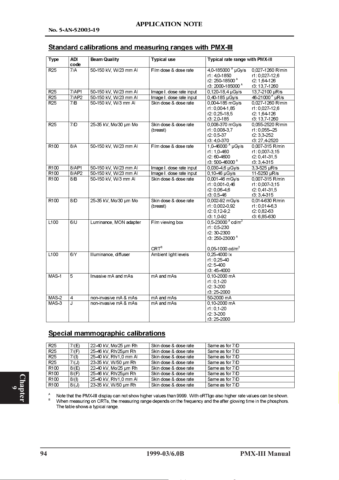
1R $1
Standard calibrations and measuring ranges with PMX-III
$33/,&$7,21 127(
Type ADI
code
R25 7/A 50-150 kV, W/23 mm Al
R25 7/AP1 50-150 kV, W/23 mm Al Image I. dose rate input 0,120-18,4 µGy/s 13,7-2100 µR/s
R25 7/AP2 50-150 kV, W/23 mm Al Image I. dose rate input 0,40-185 µGy/s 46-21000AµR/s
R25 7/B 50-150 kV, W/3 mm Al Skin dose & dose rate 0,004-185 mGy/s
R25 7/D 25-35 kV, Mo/30 µm Mo Skin dose & dose rate
R100 8/A 50-150 kV, W/23 mm Al Film dose & dose rate 1,0-46000AµGy/s
R100 8/AP1 50-150 kV, W/23 mm Al Image I. dose rate input 0,030-4,6 µGy/s 3,3-525 µR/s
R100 8/AP2 50-150 kV, W/23 mm Al Image I. dose rate input 0,10-46 µGy/s 11-5250 µR/s
R100 8/B 50-150 kV, W/3 mm Al Skin dose & dose rate 0,001-46 mGy/s
R100 8/D 25-35 kV, Mo/30 µm Mo Skin dose & dose rate
L100 6/U
L100 6/Y Illuminance, diffuser Ambient light levels 0,25-4000 lx
MAS-1 5 Invasive mA and mAs mA and mAs 0,10-2000 mA
MAS-2 4 non-invasive mA & mAs mA and mAs 50-2000 mA
MAS-3 J non-invasive mA & mAs mA and mAs 0,10-2000 mA
Beam Quality Typical use
Film dose & dose rate 4,0-185000AµGy/s
(breast)
(breast)
Luminance, MON adapter Film viewing box
B
CRT
Typical rate range with PMX-III
r1: 4,0-1850
r2: 250-18500
r3: 2000-185000
r1: 0,004-1,85
r2: 0,25-18,5
r3: 2,0-185
0,008-370 mGy/s
r1: 0,008-3,7
r2: 0,5-37
r3: 4,0-370
r1: 1,0-460
r2: 60-4600
r3: 500-46000
r1: 0,001-0,46
r2: 0,06-4,6
r3: 0,5-46
0,002-92 mGy/s
r1: 0,002-0,92
r2: 0,12-9,2
r3: 1,0-92
0,5-23000Acd/m
r1: 0,5-230
r2: 30-2300
r3: 250-23000
0,05-1000 cd/m
r1: 0,25-40
r2: 5-400
r3: 45-4000
r1: 0,1-20
r2: 3-200
r3: 25-2000
r1: 0,1-20
r2: 3-200
r3: 25-2000
A
A
A
2
A
2
0,027-1260 R/min
r1: 0,027-12,6
r2: 1,64-126
r3: 13,7-1260
0,027-1260 R/min
r1: 0,027-12,6
r2: 1,64-126
r3: 13,7-1260
0,055-2520 R/min
r1: 0,055--25
r2: 3,3-252
r3: 27,4-2520
0,007-315 R/min
r1: 0,007-3,15
r2: 0,41-31,5
r3: 3,4-315
0,007-315 R/min
r1: 0,007-3,15
r2: 0,41-31,5
r3: 3,4-315
0,014-630 R/min
r1: 0,014-6,3
r2: 0,82-63
r3: 6,85-630
Chapter
9
Special mammographic calibrations
R25 7/(E) 22-40 kV, Mo/25 µm Rh Skin dose & dose rate Same as for 7/D
R25 7/(F) 25-46 kV, Rh/25µm Rh Skin dose & dose rate Same as for 7/D
R25
R25 7/(J) 23-35 kV, W/50 µm Rh Skin dose & dose rate Same as for 7/D
R100 8/(E) 22-40 kV, Mo/25 µm Rh Skin dose & dose rate Same as for 7/D
R100 8/(F) 25-46 kV, Rh/25µm Rh Skin dose & dose rate Same as for 7/D
R100 8/(I) 25-40 kV, Rh/1,0 mm Al Skin dose & dose rate Same as for 7/D
R100 8/(J) 23-35 kV, W/50 µm Rh Skin dose & dose rate Same as for 7/D
A
B
57, (OHFWURQLFV $% 3DJH
94 1999-03/6.0B PMX-III Manual
7/(I) 25-40 kV, Rh/1,0 mm Al Skin dose & dose rate Same as for 7/D
Note that the PMX-III display can no
When measuring on CRTs, the measuring range depends on the frequency and the after glowing time in the phosphors.
The table shows a typical range.
t show higher values than 9999. With oRTIgo also higher rate values can be shown.
Page 99

1R $1
The dose detectors R25 and R100 used with the PMX-III electrometer
7KH ILJXUH EHORZ VKRZV WKH PHDVXULQJ UDQJHV IRU 30;,,, XVHG WRJHWKHU ZLWK WKH GRVH
GHWHFWRUV 5 DQG 5 5DQJHV ZLWK WKH $', PRGXOHV $3 $3 $ DQG
% DUH VKRZQ )RU 30;,,, VWDQG DORQH PHDVXUHPHQWV WKH VKRZQ XQLWV DUH WKH VDPH DV
WKH 30;,,, XVHV $OVR WKH YDOXHV DUH VKRZQ ZLWK WKH 30;,,, GLVSOD\ UHVROXWLRQ 1RWH
WKDW ZKHQ R57,JR LV XVHG WKH UDQJHV DQG WKH UHVROXWLRQ DUH LQFUHDVHG IRU VRPH $',
PRGXOHV 7KDW GHSHQGV RQ WKDW WKH 30;,,, GLVSOD\ FDQ QRW VKRZ KLJKHU YDOXHV WKDQ
DQG QR PRUH GLJLWV WKDQ IRXU :LWK R57,JR WKH UHVROXWLRQ XQLW DQG QXPEHU RI
GLJLWV FDQ EH VHOHFWHG E\ XVHU
$33/,&$7,21 127(
5V 5\V
*\V *\V *\V *\V *\V P*\V P*\V P* \V *\V
*\V *\V
*\V
*\V
*\V
*\V *\V
PMX-III stand alone
*\V *\V
Q*\V
5V 5V 5PLQ
$', $ 3
*\V *\V
$', $ 3
*\V *\V
P*\V P*\V
$', $ 3
*\V *\V
$', $ 3
*\V *\V
P*\V P*\V
*\V
$', $ 3
$', $ 3
$', $
$', %
$', $
$', %
5PLQ 5PLQ 5PLQ 5PLQ
R25R100R25R100
*\V P*\V
Q*\V *\V
Q*\V
(Valid digits and units are user selecable)
PMX-III with oRTIgo
*\V *\V
5V 5\V
Q*\V
57, (OHFWURQLFV $% 3DJH
PMX-III Manual 1999-03/6.0B 95
0HDVXULQJ UDQJH ZLWK H[WHQGHG OLPLW RI XQFHUWDLQW\ WR
$', $ 3
*\V *\V
$', $ 3
$',$DQG$',%
*\V *\V *\V
5V 5V 5PLQ
$', $ DQG $', %
P*\V *\V
P*\V P*\V P*\V *\V
5PLQ 5PLQ 5PLQ 5PLQ
±
9
Chapter
Page 100

1R
$33/,&$7,21 127(
Typical Energy
R100
Correction
kV Cq
50 0,929
55 0,956
60 0,977
65 0,991
70 1,00
75 1,005
80 1,007
85 1,007
90 1,005
95 1,002
100 0,999 65 1,006
105 0,996 70 1,010
110 0,993 75 1,011
115 0,991 80 1,008
120 0,990 85 1,006
125 0,990
130 0,991 65 1,013
135 0,992 70 1,015
140 0,994 75 1,011
145 0,997 80 1,004
150 0,999 85 1,001
Application:
kV range: 50-150 kV
Reference point: 70 kV
Anode: W
Filtration: 3 mm Al + 20 mm Al
3mmAl+1,5mmCu
3mmAl+2,0mmCu
8/A
Image Intensifier and Low
Dose/Rate Measurements
3 mm Al + 1,5 and 2,0 mm Cu
Example:
Measured or set kVp = 60 kV
Measured dose = 0,50 mGy
Correction factor Cq = 0,977 for 60 kV
Corrected dose = 0,977 x 0,50 = 0,49 mGy
Inaccuracy:
The inaccuracy of the typical correction
factor is less than ±4 %.
Note:
Check your manual to verify when you have
to do the correction manually.
-8,92E-02 4,04E-02 3,07E-06 -6,323E-09
1,04
1,00
0,96
0,92
50 60 70 80 90 100 110 120 130 140 150
Typical Correction Graph
kV
3mmAl+2,0mmCu 3mmAl+1,5mmCu 3mmAl+20mmAl
·
(QG
·
57, (OHFWURQLFV $% 3DJH
96 1999-03/6.0B PMX-III Manual
 Loading...