

Page 1

RTI | Miravue VIP-1 Manual
Contents
Miravue VIP-1 Features: ......................................................................................................................................................... 2
Best Performance Recommendations .................................................................................................................................... 2
AUDIO/VIDEO INFORMATION ................................................................................................................................................. 2
IP Network Cameras................................................................................................................................................................ 3
The VIP-1 On-Screen Source Select ......................................................................................................................................... 3
INSTALLATION OVERVIEW ...................................................................................................................................................... 4
1) VIP-1 Front Panel Ports .............................................................................................................................................. 4
2) VIP-1 Rear Panel Ports................................................................................................................................................ 5
3) Installation Diagrams ................................................................................................................................................. 7
4) VIP-1 Accessories ....................................................................................................................................................... 9
CONFIGURATION AND PROGRAMMING ............................................................................................................................... 10
5) Miravue VIP-1 Driver Configuration ......................................................................................................................... 10
6) Configure VIP-1 Driver Properties ............................................................................................................................ 12
7)
8) Controlling External Devices Via IR and RS-232 ....................................................................................................... 16
9) Miravue VIP-1 Programming Options ...................................................................................................................... 18
10) The VIP-1 Web Interface .......................................................................................................................................... 20
NETWORKING EQUIPMENT AND CONFIGURATION ............................................................................................................. 25
Unicast vs. Multicast Transmit Modes .................................................................................................................... 14
a. Accessing the Setup Web Interface .......................................................................................................................... 20
b. HDMI Configuration .................................................................................................................................................. 21
c. Network Configuration ............................................................................................................................................. 22
d. Network Video Streams ............................................................................................................................................ 23
e. Other Settings ........................................................................................................................................................... 23
f. Firmware ................................................................................................................................................................... 24
g. Actions....................................................................................................................................................................... 24
1 | Page
01/2019
Page 2

RTI | Miravue VIP-1 Manual
The Miravue VIP-1 provides AV distribution over wired and wireless Ethernet networking in the connected home
or office. The VIP-1 encodes H.264 video up to its highest supported resolution (1080p) along with audio (Dolby
5.1). The result is a high quality video output signal with low network bandwidth requirements. For the ultimate
in flexibility, the VIP-1 can be installed as a transmitter or receiver, and acts as an extension of the RTI control
system, delivering IR and RS-232 control to devices.
Miravue VIP-1 Features:
• Miravue VIP-1 can be installed as a transmitter or a receiver.*
• Supports video distribution via wired and wireless Ethernet.*
• Supports HDMI/HDCP 1.x and 2.x video sources and displays (H.264).
• Integrates network video streams (e.g., IP Cameras).
• Built-in scaler matches the display’s maximum resolution.
• Forwards IR and RS-232 commands from an RTI control system.
• Automatically provides stereo downmix with lipsync adjust for distributed audio systems.
Best Performance Recommendations
• It is critical that the networking equipment and “transmit mode” (unicast/multicast) are selected
properly or network performance will be negatively affected.
• Systems requiring more than 6 VIP-1’s should use a managed network switch.
• Each video stream occupies 15Mb of bandwidth. The total bandwidth depends on the number of video
sources and transmit mode (unicast/multicast) that is used.
• The VIP-1 should be installed as a video transmitter or a receiver. NOTE: While the VIP-1 may be
installed as a transceiver (simultaneously transmitting and receiving video), this implementation should
be tested with the video devices and network equipment that will be used.
• Video distribution via wireless Ethernet should utilize a separate wireless network. Also, due to
bandwidth requirements, limit the number of VIP-1’s to 1-2 set to Unicast mode.
• Due to an HDCP limitation, there is a maximum of 32 video connections (simultaneous views) to a
video source encrypted with HDCP.
AUDIO/VIDEO INFORMATION
Video Resolution and Audio Support
The Miravue VIP-1 transceiver encodes H.264 up to its highest supported resolution and audio (i.e., 1080p and
Dolby 5.1). If the end display cannot support the video resolution or audio format, the stream is downscaled or
downmixed accordingly. The VIP-1 does not support 4k.
Audio Extraction
Audio from the stereo-out port on the VIP-1 can be used with a centralized audio system (e.g., a whole-home
audio). If the video source is distributed (i.e., not centralized), the audio from the stereo-out port on the VIP-1
2 | Page
01/2019
Page 3

RTI | Miravue VIP-1 Manual
would need to be wired back to the centralized audio system using high-quality shielded 3.5mm male-to-male
stereo audio cables.
Audio Sync adjustment
The VIP-1 transceiver web interface setup program allows you to specify which audio stream (i.e., from the
HDMI-in port or to the HDMI-out port) is delivered to the stereo-out port and the delay in milliseconds for lipsync adjust. Only one audio stream can be selected since there is only one stereo-out port. NOTE: Audio settings
are configured via the VIP-1 web interface.
IP Network Cameras
The VIP-1 devices can view network-based camera video using RTSP camera streams.
INSTALLATION NOTES:
• MJPEG video streams are not supported.
• You cannot view a camera stream on VIP boxes that have a local source connected.
• Use only VIP-1’s that are setup as a receiver with no local source.
• Adjusting the resolution/framerate of the camera can improve the speed at which they connect.
• Tested IP cameras include: LILIN, IC Realtime, AXIS, and Alhua cameras.
The VIP-1 On-Screen Source Select
Using the On-Screen Source Select
Send the OK/Select command using IR via the RTI remote control or the TVs CEC compatible remote to display
a list of video sources available on the network. The current source is indicated by a solid bar to the right of
the source name. Use the UP and DOWN commands to navigate the menu and OK/Select to switch to the
desired video source.
The On-Screen Source List
The on-screen source list is generated using the names of the video sources on the Miravue VIP-1 network
plus any network video streams (IP cameras) added to the transceiver. Source names are defined in the twoway driver configuration in Integration Designer programming software. In addition, source names may be set
in the VIP-1 web interface.
NOTES:
• Settings made within the web interface will be overwritten by configuration settings made in the RTI
control system programming.
• Only video sources and displays that have the same 4-digit group ID (provided in the transceiver setup)
will see each other, even if there are other VIP-1 transceivers on the same physical network.
3 | Page
01/2019
Page 4
INSTALLATION OVERVIEW
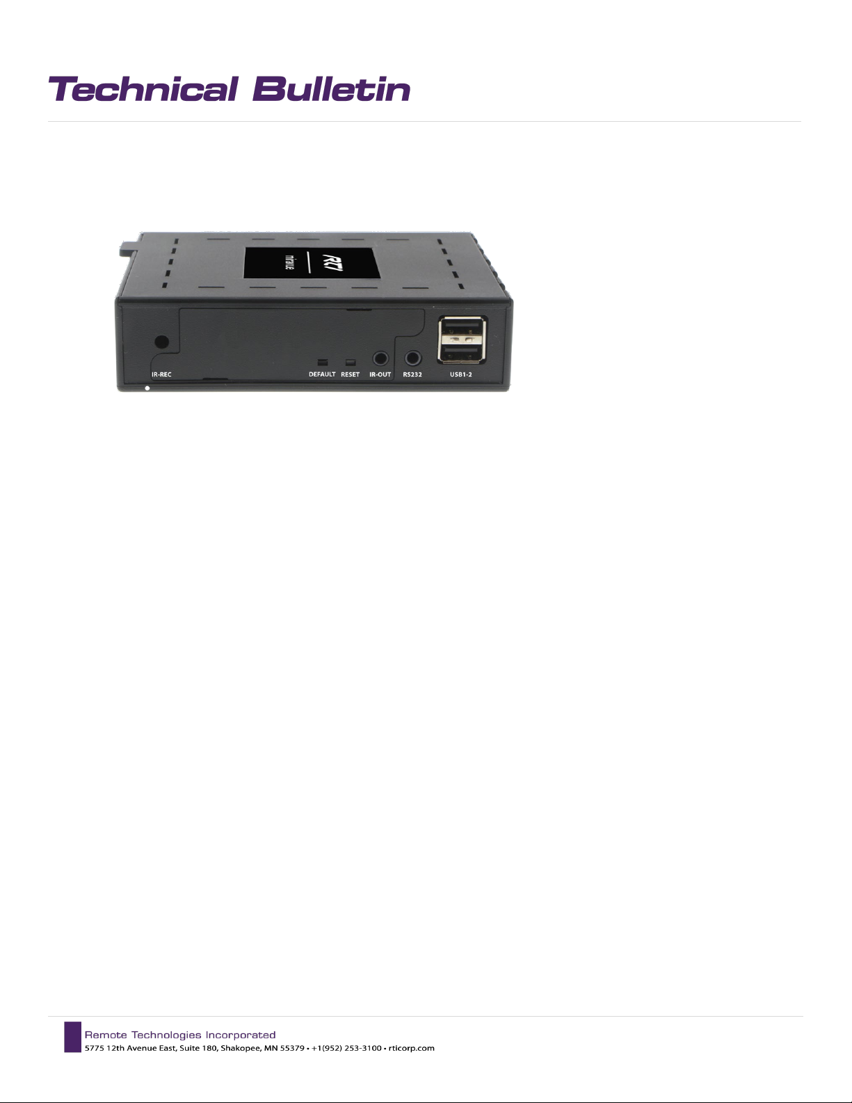
1) VIP-1 Front Panel Ports
IR-REC
Infrared receiver, used for IR control of the VIP-1 via a remote control.
RTI | Miravue VIP-1 Manual
NOTE: This IR receiver is disabled if the IR-IN port is used.
DEFAULT
Button resets the VIP-1 to factory defaults if pressed and held for 10 seconds.
RESET
Button power cycles the VIP-1 if pressed and released.
IR-OUT
• Port delivers infrared control to an external device (e.g. TV, Satellite Receiver) from an RTI control
system.
• Connect standard IR emitter to 3.5mm jack.
NOTE: VIP-1 must be configured as an expansion device in the Integration Designer system file.
RS232
• Port delivers serial communication to an external device (e.g. Projector, Blu-Ray) from an RTI control
system.
• Connect a three wire cable (Tx, Rx, and GND) between 3.5mm jack and external device.
• RS-232 Jack Pinout: Tip=Rx In, Ring=Tx Out, Sleeve=GND
NOTE: VIP-1 must be configured as an expansion device in the Integration Designer system file.
4 | Page
01/2019
Page 5
RTI | Miravue VIP-1 Manual
USB1-2
USB port is used for firmware updates (via USB thumb drive), an extra LAN port when needed (via USB to RJ45
dongle), and keyboard input (not KVM). Valid keys (select, up, down, left, right) to display and navigate the onscreen list of available sources.
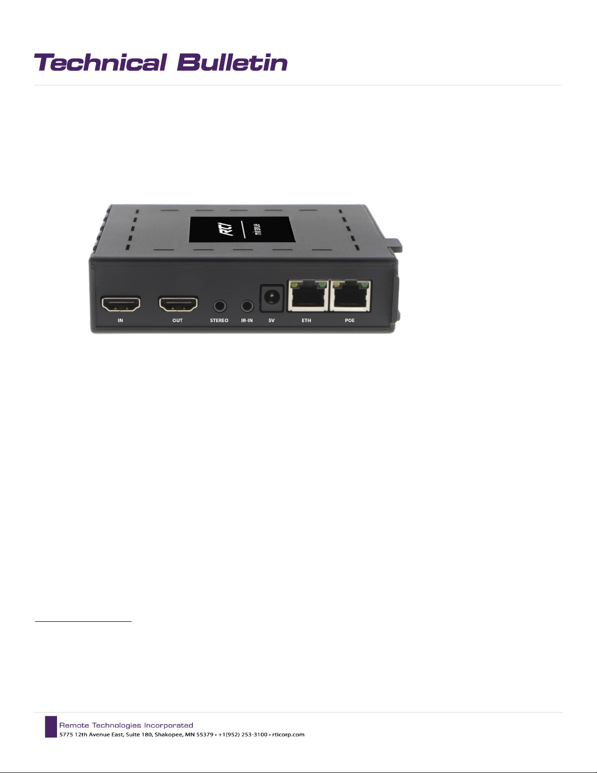
2) VIP-1 Rear Panel Ports
HDMI-IN
Connects to a video source (cable/satellite receiver, Blu-ray player, Apple TV, Fire TV, Roku). Refer to website
for supported video resolutions, audio formats, and HDMI/HDCP devices.
HDMI-OUT
Connects directly to a video display (e.g., TV or projector) or to an HDMI passthrough device (e.g., Soundbar, AV
Receiver) and then to the video display. Refer to website for supported video resolutions, audio formats, and
HDMI/HDCP devices.
STEREO
Connects to an external device's stereo audio-in port (e.g., TV, Soundbar, audio matrix). This downmixed (when
applicable) analog stream can be delayed for lip sync adjust for either the video source or the video display, but
not both. NOTE: Audio settings are configured via the VIP-1 web interface.
IR-IN
Infrared input for infrared control of the VIP-1 using an infrared receiver (purchased separately).
IMPORTANT NOTES:
• The VIP-1 IR-IN input is not compatible with IR delivered using a hard-wired cable directly from an RTI
control processor.
• IR passthrough is not supported.
• The built-in IR eye on the front panel is disabled when this jack is in use.
5 | Page
01/2019
Page 6

RTI | Miravue VIP-1 Manual
5V
Connects to the included 5VDC/2.4 Amp power supply.
NOTE: Power may also be supplied to the VIP-1 via the Ethernet - PoE port.
ETH
This port is NOT supported and should not be used.
POE
Connects to an Ethernet network switch (10/100/1000Mb, generic or managed) using Ethernet cable (Cat5/6/7) up to 100m/330ft.
6 | Page
01/2019
Page 7
RTI | Miravue VIP-1 Manual
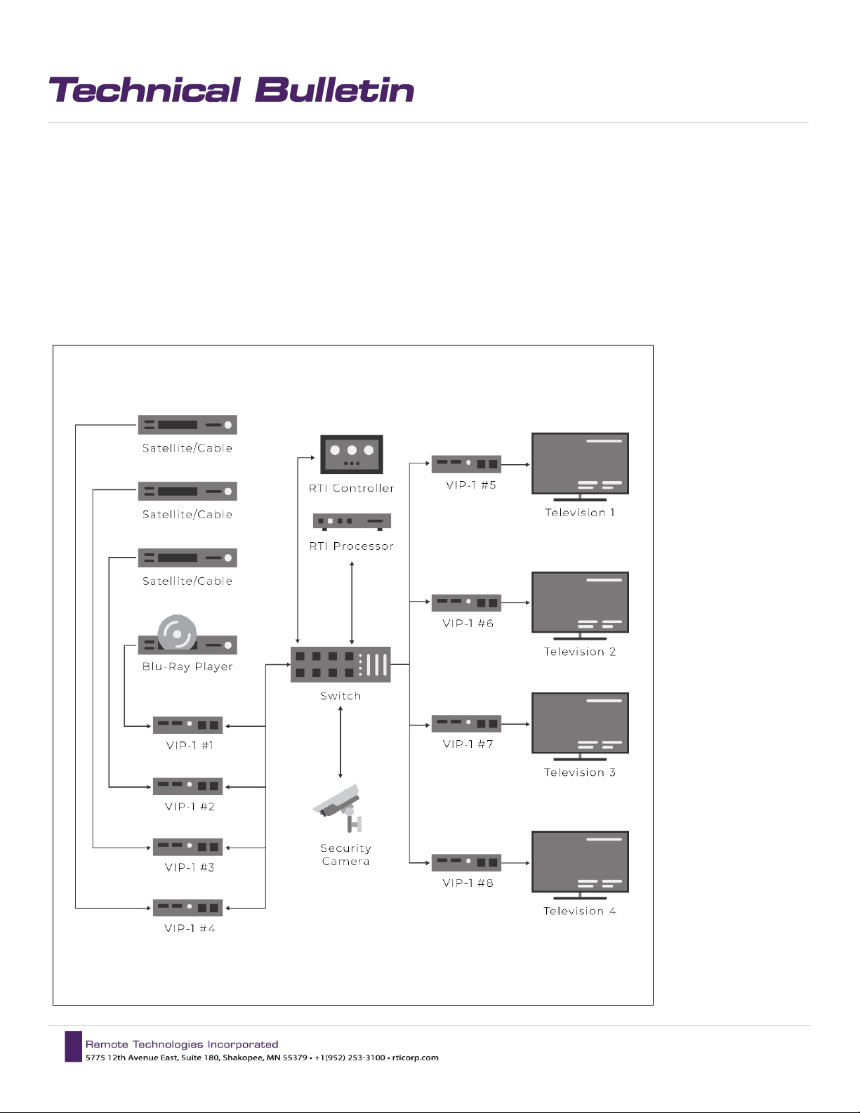
Installation Diagrams
In this Centralized Design, the VIP-1s are configured as a video transmitter or receiver. The video sources
and displays are each connected to a VIP-1.
NOTE: The VIP-1 should be installed as a video transmitter or a receiver (as shown). NOTE: While the VIP-1
may be installed as a transceiver (simultaneously transmitting and receiving video), this implementation
should be tested with the video devices and network equipment that will be used.
7 | Page
01/2019
Page 8
RTI | Miravue VIP-1 Manual
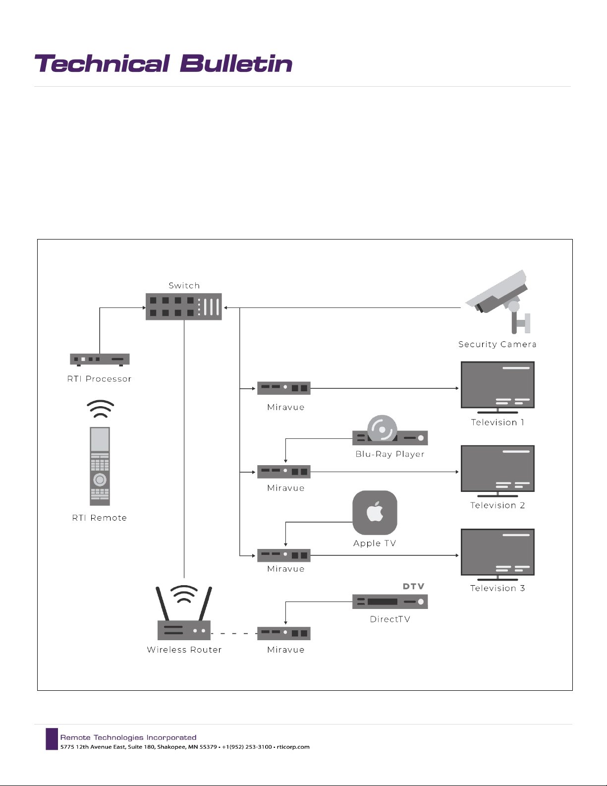
In this Hybrid Design, VIP-1’s are installed in multiple configurations, including:
- As a wired receiver
- As a wired transceiver (simultaneously transmitting and receiving video)
- As a wireless video source
NOTE: While the VIP-1 may be installed as a transceiver (simultaneously transmitting and receiving video), this
implementation should be tested with the video devices and network equipment that will be used.
8 | Page
01/2019
Page 9
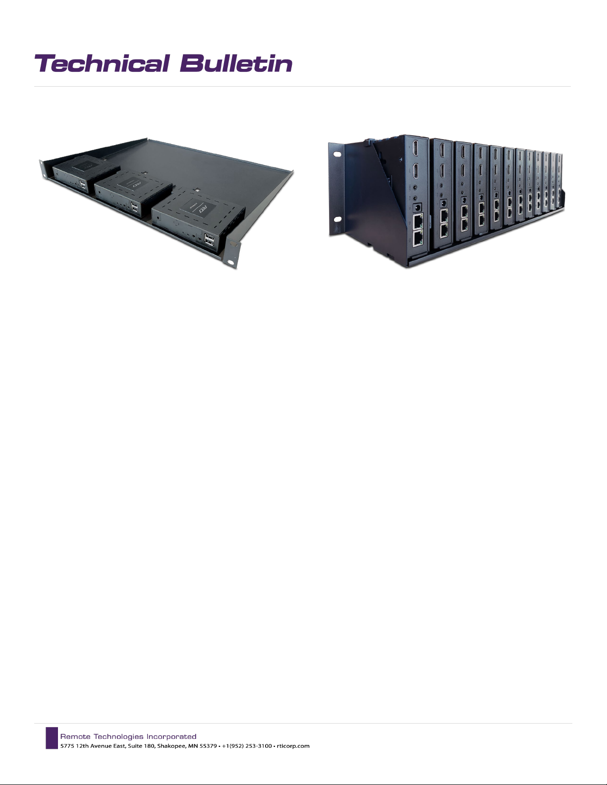
3) VIP-1 Accessories
RTI | Miravue VIP-1 Manual
RMK-3 Rack Mount Kit
for 3 VIP-1 units
RMK-12 Rack Mount Kit
for 12 VIP-1 units
9 | Page
01/2019
Page 10

RTI | Miravue VIP-1 Manual
CONFIGURATION AND PROGRAMMING
4) Miravue VIP-1 Driver Configuration
Download the current version of the Miravue driver and documentation on the RTI dealer site. Unzip the contents of the
driver to the directory where APEX points to for drivers. This can be changed by clicking the “Options” tab in the top
toolbar and selecting “set directories.”
Using the “Add Workspace Item” select the driver tab and search for “Miravue” using the search box.
Select a room or global area where the Miravue should be located and click “Next” to add the driver to APEX.
Since this is a new instance of the driver, it will automatically generate a “Transceiver 1” naming convention.
It is recommended that you change the name to something that will help you identify the device when
programming. Name it “Living Room Miravue” or “Blu-Ray Miravue” depending on the display, source, or
location it is serving. Continue this process adding all the Miravue devices to the project file.
Repeat the process to add additional devices, making sure the ”Instance” drop-down field is set to the existing
driver. This will continue to increment the Miravue count as you add more Miravue VIP-1’s.
10 | Page
01/2019
Page 11

RTI | Miravue VIP-1 Manual
11 | Page
01/2019
Page 12

RTI | Miravue VIP-1 Manual
5) Configure VIP-1 Driver Properties
Once all VIP-1 devices are added, you must configure the driver properties before continuing. Select the
Miravue driver from the driver section of the system tree and select “driver properties.” Enter the settings
required for each VIP-1 (described below). Refer to the “Driver Info” tab for additional configuration details.
Connection Type: Network (TCP)
Network: User has the option of UPnP (Serial Number), UPNP (Friendly Name), or Static Entry (IP Address)
TCP Port: Default is set to 80
Transceiver Count: Enter the transceiver count to match the number of Miravue units in your project file. This
will open configuration options for all your devices.
12 | Page
01/2019
Page 13

RTI | Miravue VIP-1 Manual
Send Configuration to Device: This checkbox allows the integrator to decide if sending an update to a
particular VIP-1 is necessary. In the event an update is needed for only one VIP-1, unchecking this box will
prevent units from needing to reboot.
Display Name: Name that is to appear in the web application, the main miravue screen, and the name that is
associated with the variable “Name”.
Source Connected: This checkbox asserts that a source is connected to the “HDMI IN” connection of the VIP-1
when checked.
Source Name: Source name that is to appear in web application, in the main miravue screen, as well as the
name that is associated to the variable “Local Source Name”.
Transmit Mode: User may choose between “Unicast” and “Multicast” depending on the system configuration.
See “Unicast vs. Multicast Transmit Modes” for important information.
Transmit Group ID: Make sure all VIP-1 units in the system use the same ID. This becomes increasingly
important when multiple systems are in the same network.
Receive Group ID: Make sure all VIP-1 units in the system use the same ID. This becomes increasingly
important when multiple systems are in the same network.
Network Discovery: The option presented here is dependent on what was selected in the “Network” portion
of the configuration under “Connection”. If “Serial Number” then enter the serial number. If “Friendly Name”
then enter the friendly name. If “Static Entry” then enter that IP Address assigned to the VIP-1 unit.
13 | Page
01/2019
Page 14

RTI | Miravue VIP-1 Manual
Unicast
3 Sources > 6 TVs
In Unicast Mode, the number of displays (wired to
6) Unicast vs. Multicast Transmit Modes
In Unicast Transmit Mode is generally recommended and is useful for small networks or for wireless video
distribution. In this mode, the VIP-1 delivers a separate video stream from a source to each display (displays do
not share video streams). If a source is not being viewed, there is no stream on the network for that source.
NOTE: In Unicast Mode, the maximum simultaneous streams from a single video source is four. If more than
four simultaneous connections to a single video source are required, multicast mode should be used.
Network Traffic
VIP-1s) viewing a video source determines the
bandwidth.
In this example, three sources viewed by six
displays generates six video streams.
1 Video Stream = 15Mbps
6 Streams = 90Mbps of Network Bandwidth
6 Video Streams
(90Mbps)
01/2019
14 | Page
Page 15

RTI | Miravue VIP-1 Manual
3 Sources > 6 TVs
In Multicast Mode, the number of sources determines the
Multicast
In Multicast Transmit Mode the VIP-1 delivers the video stream from each video source to multiple displays.
This is useful in larger systems that require more than four displays to view a source.
IMPORTANT NOTE: Caution must be taken in Multicast Mode, each video stream is delivered to every device
on the entire network, not just the display viewing it. This allows more displays to view a source, however, this
mode can “flood” the network with unwanted data, causing network performance to suffer. Therefore,
multicast mode is only recommended when a network switch with “IGMP Snooping with Query” is used, and a
VLAN or a separate network is used. IGMP Snooping with Query allows only the desired video stream to be sent
to the corresponding VIP-1, reducing network traffic and minimizing the risk of flooding a network with
unwanted packets.
Network Traffic
3 Video Streams
(45Mbps)
network bandwidth. However, each video stream is
delivered to every device on the entire network, not just
the display viewing it. See Important Note above
In this example, three sources viewed by six displays
generates three video streams:
1 Video Stream = 15Mbps
3 Streams = 45Mbps of Network Bandwidth
01/2019
15 | Page
Page 16

RTI | Miravue VIP-1 Manual
7) Controlling External Devices Via IR and RS-232
If Miravue VIP-1 devices are being utilized for IR or RS-232 control of external devices from the RTI control
system, you must set them up as expansion devices in the Integration Designer System File. Select the
processor in the system tree and then “Expansion Devices” in the partition to the right. Next, select “Add
Expansion Device” and select “VIP-1” from the list of expansion devices available.
An “Edit VIP-1” popup window will appear. For easier identification, it is recommended to name the Miravue
device the same or similar to the project file. Select the MAC radio button and enter the MAC Address you will
find on the label at the bottom side of the VIP-1 unit.
16 | Page
01/2019
Page 17

RTI | Miravue VIP-1 Manual
Continue to add expansion devices as needed, repeating the process as described. Miravue devices will now
be available as a routable MPIO or RS-232 port when adding devices in the software.
17 | Page
01/2019
Page 18

RTI | Miravue VIP-1 Manual
Select Source from List
Each display has scrolling source list capability. This command can
be used to select a source from that scrolling last.
Select Source
Used to select a source connected to a display or a Miravue device
being used as a transmitter for a source.
Open Media Stream
Open an RTSP feed by specifying the RTSP path, user and
password. Select the display and RTSP path to open the stream.
Close Media Stream
Close a current RTSP feed. Select a display that is broadcasting the
RTSP stream.
Play/Pause/Toggle Media
Stream
Play, pause or toggle the current stream broadcasting from a
display.
Send Message to Display
A message can be programmed in a macro that will send a
corresponding message.
8) Miravue VIP-1 Programming Options
When programming the Miravue using the driver, there are many macro options available.
message to any or all displays. Select the display and type a
01/2019
18 | Page
Page 19

RTI | Miravue VIP-1 Manual
Each Miravue device comes with several variables that can be used to poll a device and provide two-way
feedback.
Button State / Text Feedback
Button State / Reversed and Visible States
Object-based Feedback (2-way scrolling lists)
19 | Page
01/2019
Page 20

RTI | Miravue VIP-1 Manual
VIP-1 HDMI Output Displayed on TV/Monitor
9) The VIP-1 Web Interface
The settings that need to be adjusted via the web interface varies depending on whether the VIP-1 will be used
with an RTI control system or not.
Web Interface Settings:
• With an RTI control system: WiFi settings, Audio Offset.
• Without an RTI control system: All VIP-1 settings are configured via web interface.
IMPORTANT NOTE: If an RTI control system is used, only the WiFi and Audio Offset settings are configured via
the web interface. All other settings made via the web interface will be overwritten by the driver configuration
in Integration Designer programming.
a. Accessing the Setup Web Interface
Wired
From a web browser, enter the VIP-1 transceiver's IP
address (displayed on a TV via the HDMl-out port). If no
DHCP server is found, the transceiver assigns a default IP
address. Before entering the IP address, make sure the
connecting device is configured to the same network
segment (e.g., IP range, subnet mask, gateway, etc.)
Default IP address: 192.168.8.1
Note:
If the VIP-1 transceiver's IP address is later configured
outside the IP range of the connected device (laptop,
tablet etc), the LAN settings must be re-configured to
the same network segment before continuing. If the
network settings cannot be determined, pressing the
“DEFAULT” button for 10 seconds on the VIP-1 will
reset unit back to the factory default, and the
networking will be set to DHCP.
01/2019
20 | Page
Page 21

Transceiver Info
Serial: Product serial number
MAC address: Unique network identifier; can be
used by a DHCP server to assign a specific IP address
Firmware: Software version number
Hardware: Hardware version number
Important: The serial number, firmware version
number, and hardware version number are required
to obtain customer support
RTI | Miravue VIP-1 Manual
b. HDMI Configuration
HDMI Out
Enter a unique name for the video display device
connected to the HDMI-out port on the transceiver
HDMI In
Enter a unique name for the video source device
connected to the HDMI-in port on the transceiver (e.g.
Blu-ray). This name is used in the on-screen source list.
21 | Page
01/2019
Page 22

c. Network Configuration
Transmit & Receive Interface
Select Ethernet (default) to distribute video over a wired
network or WiFi to distribute video over WiFi (requires
5Ghz wireless access point). Always choose wired over
wireless when practical.
NOTE: WiFi must be configured via the web interface.
Interface Settings
Select DHCP (default) to obtain the transceiver's IP
address from a DHCP server or Static to set a specific
address and manually enter the IP, subnet mask,
gateway, primary DNS, and secondary DNS values where
prompted. The transceiver's IP address is displayed via
the HDMI-out port at start-up.
RTI | Miravue VIP-1 Manual
Transmit Mode (See Unicast vs. Multicast Transmit
Mode section)
Select Unicast (default), Multicast, or Disable (if no
video source device is connected). Typically unicast is
used for smaller systems (or wireless video
distribution). Multicast is used with larger systems.
(NOTE: Multicast requires a managed network switch
configured with IGMP snooping and query).
Group ID
Enter 4-digit group ID (default is 3655). Transceivers will
only see other transceivers with the same group ID. This
is used to segment transceivers on the same physical
network.
WiFi Access Point
This functionality is not supported.
22 | Page
01/2019
Page 23

d. Network Video Streams
Streaming video (e.g., IP cameras) encoded using RTSP
video codec.
NOTE: MJPEG video is NOT supported.
Name
Enter the name for the device (e.g., Front Door); used
in the on-screen source list.
IP Address
Enter a supported network streaming protocol
followed by the IP address (e.g., rtsp://10.1.0.100,
rtsp://login:pwd@10.1.0.100).
Adding / Removing Devices
Click plus or minus to add or remove a device.
RTI | Miravue VIP-1 Manual
e. Other Settings
Notifications
Enter the number of seconds (e.g., 0-10) to display
automatic "sharing with" (e.g., "Sharing with: FamilyTV") and user notifications (e.g., "Half-off special for
the next 10 minutes!"). User notifications sent via API.
Default is 4 seconds; 0 seconds means no display.
Audio Offset*
Select which audio stream, transmitter (source) or
receiver (display), is delivered to the Stereo audio out
port and the delay offset in milliseconds (used for lipsync adjust). Only one (e.g., transmitter or receiver)
can be selected since there is only one Stereo audio
out port. Dolby 5.1 audio is downmixed when
applicable.
*NOTE: This must be configured via the web interface.
Serial Port
This functionality is only used with non-RTI control
systems.
23 | Page
01/2019
Page 24

f. Firmware
Updates
It is recommended that firmware updates are
completed via a USB drive, following the instructions
included with the firmware file.
Via Setup
Select the update file using the file browse feature
(make sure this file is on the local network). Proceed
with the update.
Via USB
Follow the instructions that come with the firmware
update.
Important
Once started, do not power off the transceiver until the
update process has completed!
RTI | Miravue VIP-1 Manual
g. Actions
Save
Saves the current configuration to the transceiver.
Reboot
Power cycle's the transceiver. Performs the same function as the recessed RESET button on the transceiver.
Factory Defaults
Restores the transceiver to its factory settings. Performs same function as the “Default” button to the left of the
RESET button on the transceiver.
Important
Please reboot the transceiver any time a configuration setting has changed (prompted automatically after saving
changes).
24 | Page
01/2019
Page 25

RTI | Miravue VIP-1 Manual
NETWORKING EQUIPMENT AND CONFIGURATION
Choosing a Network Switch
You can use an unmanaged 10/100/1000Mb switch on smaller systems up to a high-end, fully managed gigabit
switch on larger systems. If you configure your network to use multicast mode, a switch that offers “IGMP
Snooping with Query” should be used. This will filter out superfluous IP traffic (i.e., sends only the desired stream
to the corresponding port so the network isn’t flooded with unwanted packets).
Three levels of network switch integration - Each level requires additional setup but improves the performance
of the VIP-1 system and other devices on the local network:
• Small systems: Unmanaged 10/100/1000 switch can be used (up to 6 VIP-1’s set to unicast mode).
• Medium Systems: Managed gigabit switch with IGMP snooping with query.
• Large Systems: Fully managed gigabit switch with IGMP snooping with query and vLAN configured for Miravue
VIP-1 traffic.
Network Bandwidth
Each video stream occupies 15Mbps on the wire. The total bandwidth required depends on the number of video
sources and the video source transmit mode being used (i.e., either unicast or multicast).
Video Distribution over WiFi
Video distribution via wireless Ethernet should utilize a separate wireless network using the 5GHz frequency
and wired to the same network. Also, due to bandwidth requirements, limit the number of VIP-1’s to one or two
set to Unicast transmit mode.
NOTE: Wireless communication is configured via the VIP-1 web interface.
Network Switch Configuration – Dell N2048P
The configuration menus and labeling depend on the make/model of the switch. These should only be used as
a general example of the setup of IGMP with Query. The setup options are highlighted in yellow.
25 | Page
01/2019
Page 26

RTI | Miravue VIP-1 Manual
26 | Page
01/2019
Page 27

RTI | Miravue VIP-1 Manual
When switching sources with more than 16 VIP-1’s to a single source at the same time in a macro, the
onscreen notifications may start flashing for a period time. To avoid this issue, make sure to include time
delays in the macro when switching large numbers of sources to multiple displays. The driver by default
disables the notifications and it is recommended that you leave it off.
Example of a macro utilizing time delays to avoid overloading the VIP transmitter.
27 | Page
01/2019
Page 28

RTI | Miravue VIP-1 Manual
Network Switch Configuration – Cisco SG350-52P switch.
The configuration menus and labeling depend on the make/model of the switch. These should only be used as
a general example of the setup of IGMP with Query. The setup options are highlighted in yellow.
28 | Page
01/2019
Page 29

RTI | Miravue VIP-1 Manual
29 | Page
01/2019
 Loading...